Article

Performance Evaluation of a Scaled-Up Membraneless Organic-Based Hybrid Flow Battery

1
Key Laboratory of Low-Grade Energy Utilization Technologies and Systems, MOE, Chongqing University, Chongqing 400030, China
2
Faculty of Electrical and Electronics Engineering Technology, Universiti Malaysia Pahang, Pekan 26600, Malaysia
3
Department of Mechanical and Energy Engineering, SUSTech Energy Institute for Carbon Neutrality, Southern University of Science and Technology, Shenzhen 518055, China
*
Authors to whom correspondence should be addressed.
Batteries 2023, 9(7), 336; https://doi.org/10.3390/batteries9070336
Submission received: 18 April 2023 / Revised: 4 June 2023 / Accepted: 8 June 2023 / Published: 21 June 2023
(This article belongs to the Special Issue Recent Progress of Flow Battery)

Abstract

:
This article presents an evaluation of the performance of a membrane-less organic-based flow battery using low-cost active materials, zinc and benzoquinone, which was scaled up to 1600 cm2, resulting in one of the largest of its type reported in the literature. The charge–discharge cycling of the battery was compared at different sizes and current densities, and its performance was evaluated under various mass transport and operating conditions. The results showed that the round-trip coulombic and voltage efficiencies were over 90% and 85%, respectively, for the laboratory-scale (1 cm2 electrode) cell, but these performances tended to deteriorate with the scaled-up (1600 cm2 electrode) cell due to inadequate mass transfer and sediment coverage of quinone, as well as the formation of a passivation film on the zinc anode. Despite this, the scaled-up batteries exhibited high coulombic and voltage efficiencies of up to 99% and 68.5%, respectively, at a current density of 10 mA cm−2. The capital cost of this system is also estimated to be several times lower than those of commercially available all-vanadium flow batteries and zinc bromide flow batteries for demand charge management applications.

Graphical Abstract

1. Introduction

With the implementation of the Paris Agreement, carbon neutrality have become the global objectives for both public and private sectors [1,2]. More countries have strengthened their commitments and set out ambitious targets in reducing greenhouse gas emissions and promoting renewable energies for sustainable developments [3,4,5]. In particular, deployments of renewable energy sources (i.e., wind and solar powers) have been effective in reducing the consumption of fossil fuels but also lead to volatile power generations due to their intermittent and unpredictable natures [6,7]. In addition to storing excess electricity, energy storage systems are a promising technology that improves the resilience of the grid for load leveling and power stabilization [8,9]. Among various energy storage technologies (e.g., mechanical and thermal), electrochemical energy storage systems, i.e., batteries, have been used extensively for a wide range of applications because of their operational and geographical flexibility [10,11].
Redox flow batteries have emerged as a promising technology for storing energies at grid scale (i.e., up to MW scale), providing superior flexibility, safety and scalability for long-duration applications [12]. Instead of storing energies in the electrodes as in most batteries, redox flow batteries store all or part of its energy in liquid electrolyte(s) that is recirculated through the cells/stacks and stored in separate reservoirs [13]. The storage capacities are mainly dependent on the amount of the soluble active species (as in true flow batteries), despite limitations due to the electrodeposition processes involved in some hybrid flow batteries [14]. This unique architecture enables a high degree of decoupling between power and energy ratings that can be adjusted readily with the suitable volume/concentration of electrolytes, ratio active surface, active surface and the number of cells/stacks, respectively.
Various redox flow batteries have been proposed, but only a few based on aqueous electrolytes have been commercialized at an industrial scale [15]. For true flow batteries, the most studied systems are all-vanadium, hydrogen–bromine and iron–chromium redox flow batteries [16,17]. These systems store energies entirely based on liquid-phase electrode reactions, while a number of hybrid flow batteries, such as zinc–bromine and zinc–ferricyanide, have been commercialized and offered higher cell voltages (>1.5 V) by involving at least one electrode reaction based on metal electrodeposition [18]. These commercialized systems have been successfully scaled-up to MW scale with costs estimated between USD 350 and 600 (kW h)−1, which are still well beyond the cost targets of major economies (i.e., <USD 100 (kW h)−1) for board market penetration in the long-term [19]. With the objectives of further reducing the capital costs, new systems of using inexpensive active materials (i.e., inorganic and organic active species) and cell components (e.g., membranes and electrodes) have been introduced using aqueous and non-aqueous electrolytes [20]; however, in the foreseeable future, non-aqueous flow batteries will still be prohibitively expensive (>USD 800 (kW h)−1) due to the uses of high-cost solvents (USD ca. 3 L−1) and low current densities (<5 mA cm−2) [21]. For aqueous flow batteries, it is known that the cost fractions of membranes are among the largest (up to 40% for low-current density systems) compared with other cell components, including electrolytes and electrodes [22].
Aqueous hybrid flow batteries based on metal electrodepositions have gained popularity, especially those with membraneless architectures that minimize direct reactions between charged species [18]. In particular, zinc has been widely used as an anodes due to its high volumetric capacity (5.85 Ah cm−3) and negative electrode potential (acidic: −0.76 V vs. SHE; alkaline: −1.29 V vs. SHE) in aqueous electrolytes [23]. At present, mainstream zinc-based flow batteries are based on membrane structures and have achieved good battery performance; however, due to the use of ion exchange membranes, they are expensive [24,25,26]. Several membraneless zinc-based hybrid flow batteries have been introduced, such as zinc–nickel [27], zinc–bromine [28] and zinc–manganese [29], which were coupled with positive electrode reactions involving solid-phase transformation, liquid-phase reaction and metal oxide electrodeposition, respectively. Meanwhile, organic active materials have received significant attention due to their abundance and availability from various sources [30]. Their properties can be tailored to improve the reaction kinetics, solubilities, and cell voltages [31]; therefore, combining membraneless architecture and organic active materials in aqueous electrolytes has been considered as a promising approach to meet the cost target of <USD 100 (kW h)−1. One example of this approach was the cadmium–chloranil flow battery proposed by Xu et al. [32] in 2009, which demonstrated a high energy density of 20 Wh L−1 and a cycle life of over 150 cycles; however, the storage capacity was limited by the positive chlorobenzoquinone electrode that relied on pure solid-phase transformation. In order to address this, Leung et al. [22] proposed an alternative system based on a zinc anode and soluble benzoquinone active species, obtaining a relatively high cell voltage of approximately 1.4 V. The operating concept was attributed to the efficient electrode reactions and the slow dissolution of zinc anodes at low acid and benzoquinone concentrations.
Although metal–organic flow batteries have shown promise, they have remained largely confined to laboratory scales with electrode areas no larger than 4 cm2 [33]. To the best of the authors’ knowledge, few studies have focused on scaling up membraneless flow batteries to demonstrate practical cell performance and share technical experiences on a significant scale; however, the positive electrode reactions of these scaled-up systems were either metal electrodeposition or solid-phase transformation, potentially resulting in storage capacities that were less expandable compared to those using soluble active species. For instance, Wills et al. [34] increased the electrode area to 100 cm2 and reported on the failure modes encountered during the scale-up process of soluble lead-acid flow batteries. It should be noted that the electrode size remained too small for industrial use. Similarly, Turney et al. [35] reported on the scale-up processes of zinc–nickel flow batteries, in which a prototype was constructed at kW scale by connecting thirty batteries (each with eight to nine electrodes; each electrode was 90 cm2) in a series. The study found that anode passivation and zinc particulate clogging were the primary reasons for deterioration in cell performance and failure. Additionally, the absence of a membrane did not offset the high cost of the positive nickel hydroxide electrode, which resulted in a cost of over USD 400 (kW h)−1, well above the competitive target of $100 (kW h)−1.
This study aimed to scale up a membraneless metal–organic flow battery (1600 cm2) using low-cost active materials (zinc and benzoquinone) and to evaluate its performance under various mass transport and operating conditions. Experimental and numerical studies were conducted to compare the charge–discharge cycling of this battery at different sizes, and current densities. The scaled-up batteries demonstrated high coulombic and voltage efficiencies of up to 99% and 68.5%, respectively, at a current density of 10 mA cm−2; however, insufficient mass transfer and sediment coverage resulted in performance deterioration. Nonetheless, this study successfully scaled up the laboratory-scale cell to one of the largest scales of existing membraneless flow batteries, providing technical insights for improving battery performance and promoting practical applications. These findings are of significant interest for advancing the development of membraneless flow batteries based on low-cost and sustainable active materials.

2. Experimental Details

2.1. Experimental Materials

Chemical reagents, including hydrochloric acid (HCl, 98% AR, Chengdu Colon Chemical Company, Chengdu, China), zinc chloride (ZnCl2, 98% AR, Shanghai Yien Chemical Technology Company, Shanghai, China), hydroquinone (HQ, >99% AR, Beijing Jinming Biotechnology Co., Beijing, China), and sodium chloride (NaCl, 99.8% GR, Shanghai Boer Chemical Reagents Co., Shanghai, China) were purchased and used as received without further purification. A high-purity zinc plate (99.9% purity, Ainin Company, Chongqing, China) and carbon felt (GFD 4.6EA-TA, with a thickness of 0.6 cm, SGL Carbon, Wiesbaden, Germany) were used as the negative and positive electrodes of the hybrid flow battery, respectively.

2.2. Electrode Pretreatment

For the positive electrodes, a carbon polyvinyl–ester composite plate with high-purity carbon (Senjiu Graphite Company, Xinxiang, China) was used as a current collector. The negative electrode were high-purity zinc plates (99.9% purity, Ainin Company, China). Prior to conducting the experiments, both electrodes were polished with silicon carbide and degreased with detergent, followed by cleaning in an ultrasonic bath for over 20 min. In order to remove the surface oxides, the electrodes were immersed in diluted hydrochloric acid (0.1 M) for 1 h. The porous carbon felt electrode was thoroughly rinsed with copious amounts of water after being treated with detergent and subjected to an ultrasonic bath. It was subsequently affixed to the carbon plate current collector by either compression or plastic screws. Chemically resistant polyester tapes were used to cover the electrodes, thereby ensuring that the required active areas were exposed to the electrolyte for effective electrode reactions.

2.3. Flow Battery Experiment

The feasibility of membraneless metal-organic hybrid flow batteries were evaluated under scale-up by using two batteries with electrode areas of 1 cm2 and 1600 cm2 in this study. The primary electrode reactions for storing energies were zinc electrodeposition on the planar substrate surface at the negative electrode, while the oxidation of 1,4-hydroquinone took place through the porous carbon-felt electrode at the positive electrode, as reported in previous work [36].
At negative electrode:
Z n 2 + + 2 e Z n           E 0 = 0.76   V vs. SHE
At positive electrode:
Batteries 09 00336 i001    Eo = +0.64 V vs. SHE
Both electrode reactions were reversible and underwent two electron-transfer processes, resulting in an overall cell voltage of ca. 1.4 V in acidic electrolytes. The membraneless configuration enabled single electrolytes to be recirculated through the batteries by pumps to improve the mass transport of active species. The electrical and electrolytic circuits utilized were identical to those employed in previous cells that operated on the same principles [37]. Unless otherwise stated, a single electrolyte of 1 M zinc chloride (ZnCl2), 0.1 M 1,4-hydroquinone (HQ) in 2.5 M sodium chloride (NaCl), and 0.1 M hydrochloric acid (HCl) was used as the starting electrolyte (i.e., 0% State-of-charge), which was prepared using deionized water with a resistivity of 18 MΩ cm. The applied current densities always referred to the negative zinc anodes based on the exposed areas of the plate surface to the electrolytes.
(i)
Laboratory-scale battery (1 cm2 electrode):
The charge–discharge performance of a small-scale hybrid flow battery with 1 × 1 cm (1 cm2) areas of the electrode exposed to the electrolyte was evaluated using a commercial cell (Changsha Spring Company, Changsha, China) that was modified into a membraneless configuration. The experimental setup is illustrated in Figure 1a, with an expanded view of the small-scale flow battery shown in Figure 1b. The battery comprised two stainless-steel end-plates, acrylic supporting plates, acrylic flow channels, a PTFE compressing plate with perforations, a zinc anode, a porous carbon-felt cathode, and a carbon-plate current collector. The flow battery was equipped with an inlet and an outlet situated at the lower and upper sides, respectively. During the experiments, a single electrolyte of 100 mL was circulated to and from the flow battery by a peristaltic pump (Lead Fluid Co., China) from 0.05 to 0.07 cm s−1. Galvanostatic charge–discharge cycling was carried out at constant current densities between 10 and 30 mA cm−2 (10 and 30 mA) under a 15 min charge–15 min discharge regime using a potentiostat (BP-300, Biologic SAS, France). The cut-off voltages were set between 0 and 1.6 V to prevent overcharging or over-discharging.
(ii)
Scaled-up battery (1600 cm2 electrode):
A membraneless hybrid flow battery with exposed electrode areas of 40 cm × 40 cm (1600 cm2) to the electrolyte was constructed, utilizing a scaled-up cell design similar to that of Turney et al. [35]. The battery was fabricated from chemically resistant acrylic to ensure durability and stability in slightly acidic electrolytes (see Figure 1c). Unlike the 1 cm2 electrode battery using compression, the positive carbon felt electrodes were mounted to the carbon plate current collector through plastic screws. The electrode plates of negative zinc anode and positive carbon plate cathode stood upright and parallel to each other. An inter-electrode gap of 15 mm was used to prevent electrical shorting caused by potential dendritic formation at the negative zinc electrode. The inlet and outlet of the flow battery were located at the lower and upper sides, respectively, to enable proper recirculation of electrolyte through the cell. A plastic centrifugal pump (ZKSJ Company, Hangzhou, China) was used to circulate the electrolyte at various flow velocities, ranging from 100 to 250 cm s−1. A large current battery testing system (Shenzhen Xinqingyuan Ltd., Shenzhen, China) was used to carry out galvanostatic charge–discharge cycling at a constant current density of 10 mA cm−2 (16 A), utilizing 15 min charge–15 min discharge regime. The cut-off voltages were set between 0 and 2.8 V to prevent overcharging or over-discharging.

2.4. Electrochemical Impedance Spectroscopy

The pristine and used carbon felts of the cycled batteries were measured by electrochemical impedance spectroscopy. The measurements were acquired using a BP-300 potentiostat (Biologic SAS, France) in a potentiostatic mode, with a voltage amplitude of 10 mV applied at the open circuit voltage. The measurements were performed within a frequency range of 1 MHz to 10 mHz, and each measurement required up to 20 min.

2.5. Physicochemical Characterizations

The membraneless hybrid flow batteries based on low-cost active materials were the subject of investigation. Physicochemical characterizations of the electrolyte and electrode materials were conducted to elucidate the reaction and mass transfer mechanisms in the charge–discharge cycling processes.
The following three aspects were analyzed:
(i)
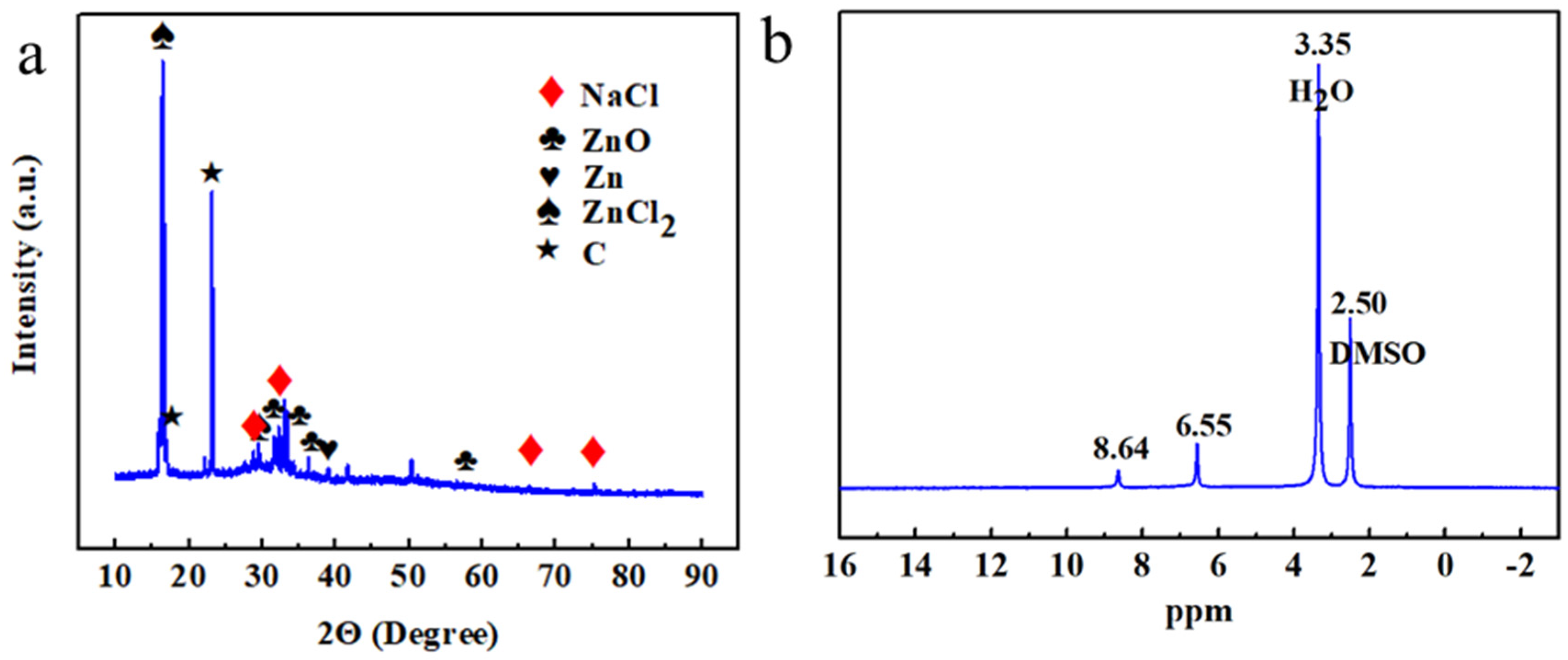
Electrolyte characterizations: X-ray diffraction (XRD, D8 Advance, Brucke Corp., Germany) analysis was conducted on the dried products, i.e., sediment and floating foam, obtained from the electrolytes after prolonged charge–discharge cycling, and finely powdered using an agate mortar.
(ii)
The aim of this analysis was to investigate the crystal structure and phase composition of the dried substances under test conditions of 5–90° 2θ and a scan rate of 10° min−1. X-ray diffraction profiles were matched with standard Powder Diffraction FileTM (PDF) cards using analysis software (Jade6.5). Fourier Transform Infrared Spectroscopy (FTIR, Nicolet IS 10, Thermo Scientific, Waltham, MA, USA) was used to characterize the functional groups present in the organic dried substances, which were subsequently analyzed to determine the molecular structures of organic compounds. The sample to be tested was thoroughly crushed by mixing it with potassium bromide at a mass ratio of 10:1 and then pressed into a specific mold to form nearly transparent circular pellets. Finally, the resulting pellets were placed in the infrared sample tank for testing, and the wave number range was set to 400–4000 cm−1.
(iii)
Nuclear Magnetic Resonance Spectroscopy (NMR, JNM-ECZ600R, Japan) was utilized to qualitatively analyze the composition and structure of the dissolved organic compounds, thereby providing insights into the underlying reaction mechanisms. The solvent for nuclear magnetic resonance spectroscopy is methyl sulfoxide (DMSO).
(iv)
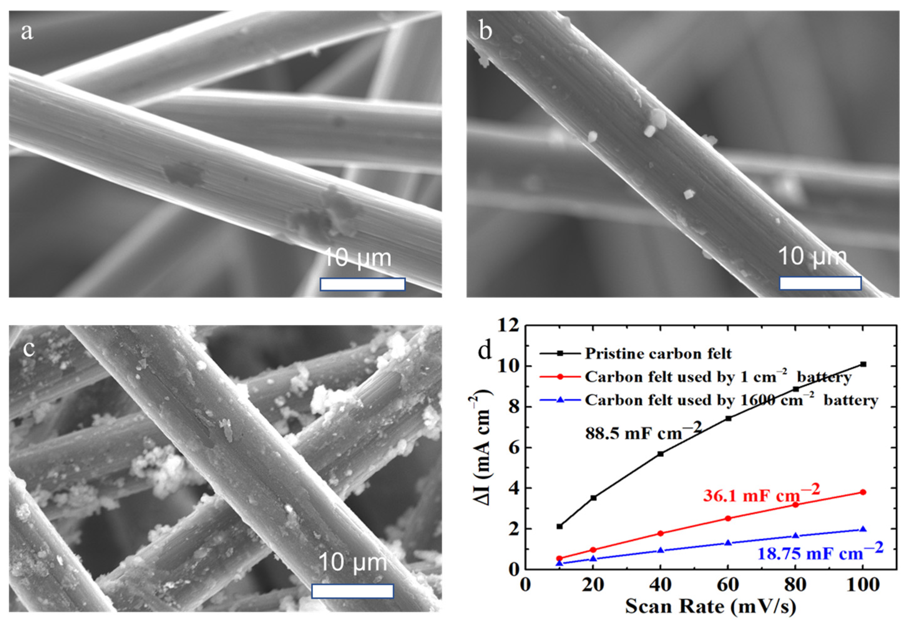
Positive electrode characterizations: scanning electron microscopy-energy dispersive spectroscopy (SEM-EDS) was used to analyze the surface morphology, element composition, and organics adhesion of the carbon felt electrode before and after charge–discharge cycling. Scanning electron microscopy (SEM, TM4000Plus, Hitachi, Japan) was performed to observe the morphology and microstructure, operated at 20 kV and 10 mA, and analysed the adhesion and distribution of the sediments in the carbon felt. Energy dispersive spectroscopy (EDS, Hitachi, Japan) was performed to analyse the sediments, and the samples were irradiated with an electron gun to obtain the compositions and content of precipitates on carbon felt.
(v)
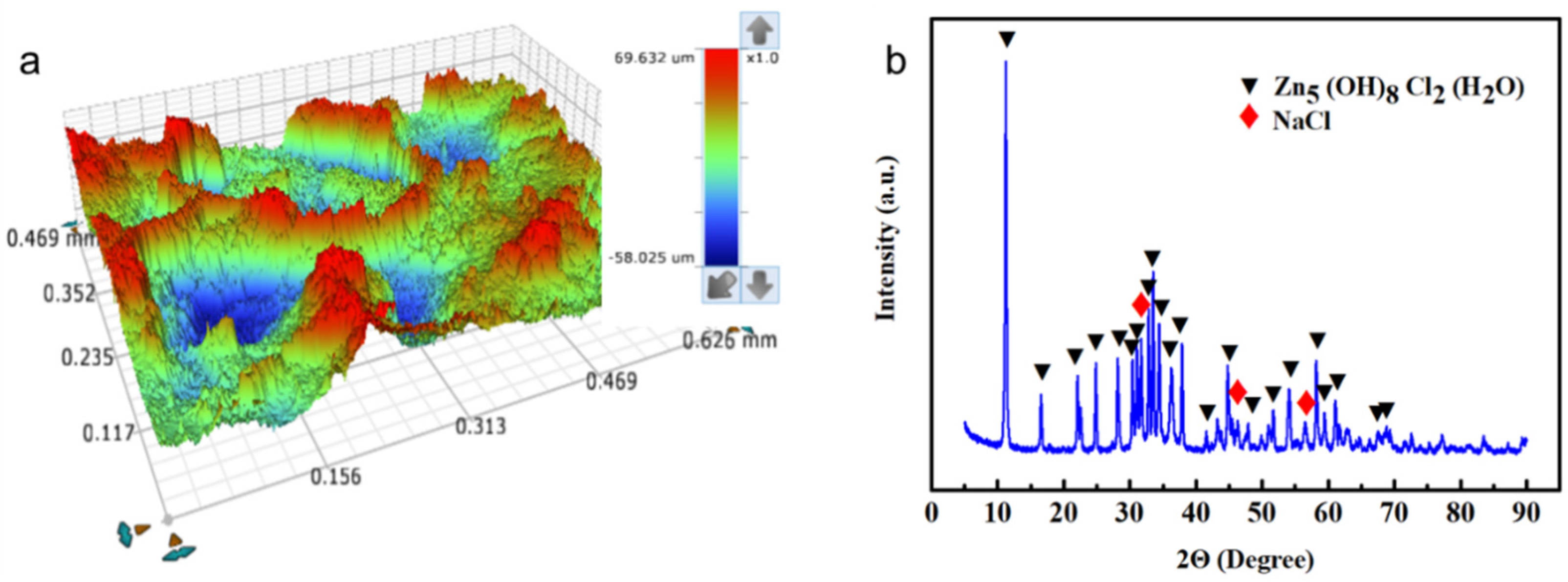
Negative electrode characterizations: three-dimensional contour scanner (Contoure GT-X, Bruker Corp., Germany) and scanning electron microscopy (SEM) were employed to investigate the crystal structure and phase composition of the zinc anode surface after prolonged charge–discharge cycling. The three-dimensional contour scanner was used to provide a high-resolution topographic map of the zinc anode surface by providing the precise measurements of surface roughness. These two techniques provided direct microscopic information on the morphologies of the zinc anode.

3. Results and Discussions

3.1. Performance Comparison with the Scaled-Up Hybrid Flow Batteries

Membraneless hybrid flow batteries based on low-cost elements have emerged as a promising solution for achieving a cost target of less than USD 100 (kW h)−1 and enabling widespread market penetration; however, the scale-up to a significant size is essential for enabling practical applications. The scalability of these batteries is of significant interest, particularly with regard to their performance at larger scales. This study is the first to scale-up a membraneless hybrid flow battery from a laboratory-scale cell featuring a 1 cm2 electrode to a 1600 cm2 cell, resulting in one of the largest of its type reported in the literature. The objective of this work was to evaluate the influences of this scale-up process on the battery performances in terms of charge–discharge cycling efficiencies and profiles under identical operating conditions.
Figure 2a,b show the charge–discharge cycling performances of the laboratory-scale (1 cm2 electrode) and scaled-up (1600 cm2 electrode) hybrid flow batteries, respectively, at 10 mA cm−2 for 50 cycles (Figures S2 and S3), while their inset shows the corresponding charge–discharge profiles at 10, 20 and 30 mA cm−2. It can be seen that the laboratory-scale (1 cm2 electrode) cell showed relatively flat and stable charge–discharge profiles, while the potential differences between the charge and discharge voltages were only 170–490 mV for these current densities (10–30 mA cm−2) (Figure 2a and Figure S4). The round-trip coulombic and voltage efficiencies were over 90% and 85%, respectively, leading to stable energy efficiencies of ca. 77% at 10 mA cm−2 however, these performances tended to deteriorate with the scaled-up (1600 cm2 electrode) cell, indicating the importance of further investigation into mass transport phenomena within these larger batteries, which will be investigated in the next section using multiphysics software.

3.2. Mass Transport Analyses Based on Multiphysics Models

In order to enhance the comprehension of the movement of active species and electrolytes within a scaled-up hybrid flow battery, the electrochemical reactions and mass transport phenomena were simulated through the use of multiphysics software (COMSOL Multiphysics®), and the model assumptions are shown in detail in the Supporting Materials. By visualizing the distributions and flow velocities of the soluble active species, numerical simulations based on experimental conditions offer insight into the underlying transport phenomena of these scaled-up batteries. During the charging process, the active zinc(II) and hydroquinone species were reduced and oxidized at the negative and positive electrodes, respectively.
After the model is validated (Figure S5), the flow velocities (Figure 3a) and concentration distributions of these active species (Figure 3b–d: hydroquinone; Figure 4: zinc ion) within the scaled-up batteries were simulated at 10 mA cm−2 during charging at t = 890 s (other simulation data can be found in Figures S6–S9). The results revealed that the flow velocities were higher along the negative zinc electrode than within the porous positive electrodes, significantly hindering the electrolyte flow. The slower flow velocities within the positive electrode tended to result in poorer uniformity and mass transport of the active species, as observed in the case of the hydroquinone species. The concentration of the hydroquinone active species decreased rapidly at the positive electrode when the single electrolyte was flowing upward to the outlet at the end of the charge cycle (Figure 3b,d). This was attributed to the large consumption of hydroquinone at the positive electrode; however, the mass-transfer resistance remained high, and the active cannot be replenished readily. Furthermore, the lower concentration of hydroquinone species (0.1 M) prepared in the starting electrolytes was used to minimize direct reactions between the charged species and ensure the membraneless configuration. Consequently, the concentration polarizations of the positive quinone electrode reaction were particularly challenging, leading to lower performance at higher charge–discharge rates (Figure 2b and Figure S10). On the other hand, the zinc(II) ion concentration remained high (e.g., >0.945 M) in all parts of the scaled-up battery (Figure 4), while flow velocities and concentration distributions of both active species were superior in the laboratory-scaled batteries (Figures S11 and S12), indicating that mass-transport limitations were not an issue in such scenarios.
Furthermore, after charge–discharge cycling, the electrodes and electrolytes were characterized in terms of morphological and chemical changes to gain further insights into the behavior and performance of the scaled-up hybrid flow battery, providing information regarding the degradation mechanisms and the stability of the battery components.

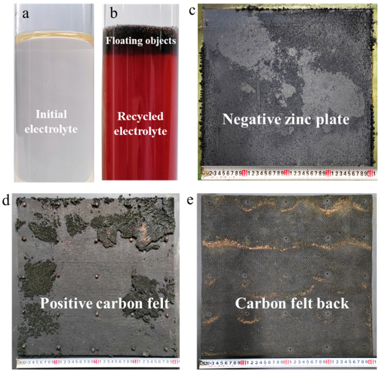
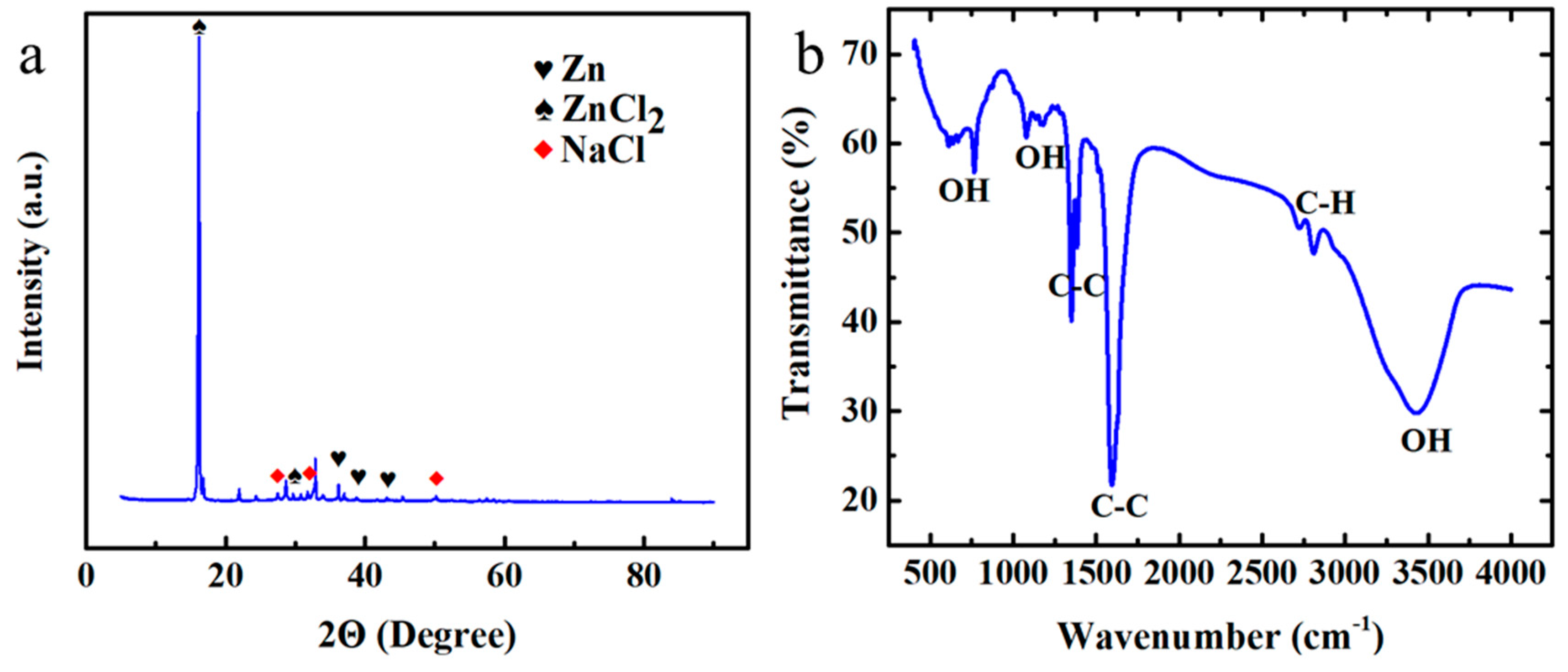
3.3. Characterization Analyses of Cell Components after Charge–Discharge Cycling

After completing the charge–discharge cycling, the electrolyte used in the scaled-up battery was observed to change from transparent (Figure 5a) to red (Figure 5b). This was hypothesized to be due to the oxidation of hydroquinone to benzoquinone, resulting in coloration. Subsequently, cycling tests revealed the presence of a layer of black-colored particles floating on the electrolyte (Figure 5b), possibly resulting from the detachment of organic substances and carbon materials from the battery components during prolonged cycling. Upon dismantling the batteries, yellow-brown and black-colored substances were observed on the surfaces of the zinc electrode deposits (Figure 5c), which were likely the result of corrosion after removal from the chloride electrolyte. Significant amounts of branch- or rod-like structures were also observed at the edges of the zinc anodes, consistent with the previously reported dendritic formations in zinc-based hybrid flow batteries. Zinc dendrites are not easily attached to the negative electrode, and the detached zinc dendrites can cause a decrease in battery discharge capacity. The uneven distribution of zinc dendrite deposition also leads to its inability to be completely consumed during discharge, which seriously affects battery performance, especially for high-current batteries.
As for the positive electrodes, layers of a light-yellow-colored substance (3–5 mm) were observed on the surfaces of the carbon-felt electrode (Figure 5d). These substances that were not present in 1 cm2 electrode cell were found to have spread or penetrated into the porous structure of the electrode and accumulated on the back of the carbon felt near the carbon current collector (Figure 5e). It was hypothesized that these layers of yellow substance were benzoquinone formed during the electrochemical reactions, which precipitated due to its low solubility in water. Consequently, detailed characterization tests were conducted to analyze the compositions of these materials.
The floating suspension of the electrolyte was collected and dried in a vacuum drying oven at 60 °C for 720 min. It was then analyzed through XRD (Figure 6a), which showed peaks corresponding to metallic and carbon substances, such as sodium chloride (PDF#01-072-1668), zinc oxide (PDF#01-075-1526), zinc (PDF#04-0831), zinc chloride (PDF#16-0850), and chloride (PDF#50-0926). The sodium and zinc chloride likely refer to the supporting salts in the electrolyte, while the metallic zinc may have detached from the anode in the form of zinc dendrites, and the zinc oxide may have formed due to the oxidation of zinc upon contact with air; however, no relevant spectral information related to the metal substances was found for peaks at 50.3° and 41.7°, which were presumed to be related to carbon or organic substances and were further characterized. For instance, 1H NMR (Figure 6b) detected the hydrogen atoms of phenol (HPH-00-23) at chemical shifts of 8.6 ppm and 6.5 ppm, while FTIR spectroscopy (Figure S13) identified absorption peaks corresponding to C-C bonds (1500 cm−1, 1632 cm−1) and C-H bonds (2712 cm−1, 2833 cm−1) [38], suggesting the presence of hydroquinone in this suspension. Moreover, some traces of carbon fibers detached from positive carbon felt electrodes were observed in this floating suspension through SEM (Figure S14); therefore, the floating suspension, consisting of various inorganic substances and organic components, not only impeded the electrolyte flow but also caused short circuits when connected to the negative and positive electrodes, resulting in a deterioration in battery performance.
Regarding the negative zinc electrode, the morphologies of the electrodeposits was analyzed using a three-dimensional contour scanner (Figure 7a and Figure S16) after prolonged cycling. The results revealed a rough surface with irregularities of up to 100 μm, indicating that the zinc electrodeposition–dissolution processes were uneven and had caused some degree of shape change. These grooves were visible as corrosion marks at the macroscopic level. The XRD analysis of the electrodeposit on the zinc anode (Figure 7b) showed peaks similar to the standard pattern of simonkolleite (Zn5(OH)8Cl2(H2O)), with traces of sodium chloride (PDF#01-072-1668) also present. This was because the initial proton concentration (0.1 M) decreased due to continuous hydrogen evolution, leading to less acidic electrolytes (higher pH). In such a case, Zn2+, OH, Cl in the electrolytes reacted with water to form Zn5(OH)8Cl2(H2O) [39]. It was a passivation film that not only exhibited low activity but also affected the direct contact of the electrolyte with the zinc anode.
For the positive electrode, the carbon-felt electrode may contain solid substances that have accumulated and penetrated into its porous structure. The SEM images of the pristine and used carbon-felt electrodes (Figure 8a–c) reveal the presence of more solid substances in the scaled-up battery compared to its laboratory-scale counterpart. These solid substances can hinder battery performance by reducing porosity in specific areas. The electrochemically active specific surface areas (ECSA) of the active sites with the electrolytes were estimated using the double-layer capacity (Cdl) measured in the non-Faraday reaction region using cyclic voltammetry (Figure S17) [40,41,42]. The pristine carbon felt exhibited a Cdl of 89 mF cm−2, whereas the laboratory-scaled and scaled-up battery carbon felts showed Cdl values of 36 and 19 mF cm−2, respectively (Figure 8d). This confirms that the solid substances formed during prolonged cycling can clog or cover the carbon felt, leading to reduced active areas. The Nyquist plots of various carbon felts are depicted in Figure S18, where the carbon felt employed in the 1600 cm2 electrode battery demonstrates the highest charge transfer resistance, providing further evidence that the formation of solid substances during prolonged cycling has a significant negative impact.
The XRD analysis was performed on the solid substances that had accumulated on the carbon-felt electrode surfaces and were dried at 60 °C for 720 min. Figure 9a illustrates the XRD peaks that correspond to metallic zinc (PDF#04-0831), sodium chloride (PDF#05-0628), and zinc chloride (PDF#39-0887), while some peaks at 32.8° and 21.8° may indicate the presence of certain organic compounds that were subsequently analyzed. Figure 9b displays adsorption peaks at 3426 cm−1, which correspond to hydroxyl groups, and two adsorption peaks near 2825 cm−1 that may indicate C-H bonds. The peaks at approximately 1596 cm−1 and 1384 cm−1 were likely to be C-C bonds on the benzene ring [39]. Absorption peaks at around 1077 cm−1 and 766 cm−1 may be attributed to the hydroxyl groups, which were possibly phenolic substances. Analysis of 1H NMR (Figure S19) indicated hydrogen atoms of hydroquinone (HPH-00-23) at chemical shifts of 8.6 ppm and 6.5 ppm, and hydrogen atoms of p-benzoquinone (HPH-00-69) at 6.88 ppm. The solid substances on the surfaces of the carbon felt electrodes have been identified as a mixture of metallic zinc, quinone, and electrolyte salts based on the characterizations performed. The formation or precipitation of these solids may potentially lead to a decrease in the concentrations of the active materials in the electrolytes. Future work may explore improved electrolyte compositions to address this issue.

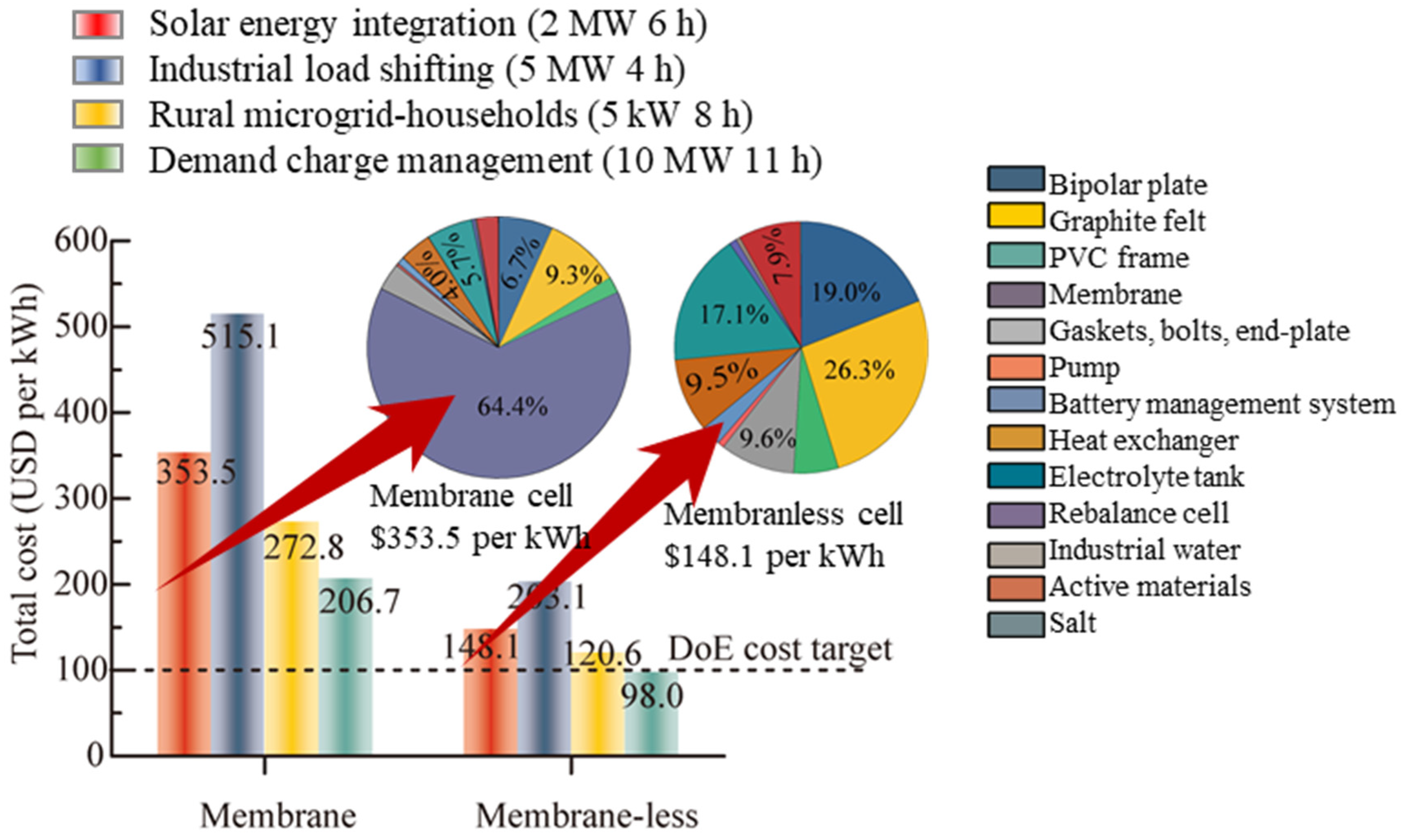
3.4. Capital Cost Analysis of Membraneless Hybrid Flow Batteries

The influences of membranes on the capital costs of the zinc–organic hybrid flow battery provides important insights into the economic feasibility of this chemistry for large-scale energy storage applications. As shown in Figure 10, the analysis assumed a current density of 30 mA cm−2 for four energy storage applications, namely, solar energy integration, industrial load shifting, rural micro-grid households, and demand charge management. The maximum and minimum costs of a membrane-based battery, which shares the same chemistry as a non-membrane-based battery, were determined to be USD 515.1 (kW h)−1 and USD 206 (kW h)−1, respectively. A significant reduction in the capital cost can be achieved by eliminating the ion exchange membrane. Specifically, the cost of the membraneless hybrid flow battery was found to be 60% lower than that of the membrane-based battery. This reduction is mainly attributed to the elimination of the cost associated with the membrane, which accounts for the majority of the capital cost of the battery. Moreover, the cost of the membraneless hybrid flow battery for the demand charge management application (10 MW × 11 h) was only USD 98 (kW h)−1, which is lower than the long-term market competitiveness target of <USD 100 (kW h)−1. This cost is also lower than that of commercially available all-vanadium flow batteries (>USD 300 (kW h)−1) and zinc bromide flow batteries (>USD 300 (kW h)−1). In the event that mass transport limitations and the stability of the cell components are addressed, and the current density becomes comparable to that of other commercial flow batteries (e.g., >50 mA cm−2), the capital cost of the membraneless hybrid flow battery may be further reduced, resulting in additional cost advantages over other energy storage technologies. Overall, these findings suggest that the membraneless hybrid flow battery holds potential as a competitive energy storage technology for large-scale applications. Nonetheless, additional research is necessary to enhance the battery’s performance and reduce its capital cost to render it a more economically viable alternative.

4. Conclusions

This study evaluated the performance of a membraneless organic-based flow battery using low-cost active materials, namely zinc and benzoquinone, by scaling it up to 1600 cm2. The charge–discharge cycling of the battery was compared at different sizes, current densities, and its performance was evaluated under various mass transport and operating conditions. The results indicated that while the round-trip coulombic and voltage efficiencies were over 90% and 85%, respectively, for the laboratory-scale (1 cm2 electrode) cell, these performances tended to deteriorate with the scaled-up (1600 cm2 electrode) cell. The slower flow velocities within the positive electrode resulted in poorer uniformity and mass transport of the active species, leading to lower performance at higher charge–discharge rates. Despite this, the scaled-up batteries exhibited high coulombic and voltage efficiencies of up to 99% and 68.5%, respectively, at a current density of 10 mA cm−2, showcasing the potential of this low-cost battery technology; however, inadequate mass transfer and sediment coverage of quinone, as well as the formation of a passivation film on the zinc anode, led to performance deterioration. The zinc(II) ion concentration remained high throughout the scaled-up battery, while flow velocities and concentration distributions of both active species were superior in the laboratory-scale batteries, indicating that mass transport limitations were not an issue in such scenarios. The study also conducted characterization analyses of the cell components after charge–discharge cycling to gain further insights into the degraded performance of the scaled-up hybrid flow battery, providing information on the stability of the battery components (i.e., electrolytes and electrodes). These findings are significant for advancing the development of membraneless flow batteries based on low-cost and sustainable active materials and providing valuable technical insights for improving battery performances and promoting practical applications. It is noteworthy that the capital cost of this system is several times lower than those of commercially available all-vanadium flow batteries (>USD 300 (kWh)−1) and zinc bromide flow batteries (>USD 300 (kW h)−1) for demand charge management application (10 MW × 11 h). Furthermore, this study is the first to scale-up a membraneless hybrid flow battery from a laboratory-scale cell featuring a 1 cm2 electrode to a 1600 cm2 cell, resulting in one of the largest of its type reported in the literature.

Supplementary Materials

The following supporting information can be downloaded at: https://www.mdpi.com/article/10.3390/batteries9070336/s1, Figure S1: schematic diagram of membraneless flow battery model. Figures S2–S21: electrochemical tests and material characterizations.

Author Contributions

Conceptualization, P.L. and F.Y.; methodology, F.Y.; software, F.Y., M.R.M. and A.S.; validation, F.Y. and W.Z.; formal analysis, F.Y. and W.Z.; writing—original draft preparation, F.Y. and W.Z.; writing—review and editing, M.R.M., L.W., A.S. and P.L.; visualization, F.Y.; supervision, P.L., L.W. and Q.L.; project administration, P.L.; funding acquisition, P.L., L.W. and Q.L. All authors have read and agreed to the published version of the manuscript.

Funding

This work is supported by the Innovative Research Group Project of the National Natural Science Foundation of China (No. 52021004), the Funds for Chongqing Talents Plan (No. CQYC2021059563), the Fundamental Research Funds for the Central Universities (No. 2021CDJQY-027), the National Natural Science Foundation of China (No. 52206089) and the Universiti Malaysia Pahang (UMP) through Postgraduate Research Grant Scheme (PGRS) under Modelling of Adaptive Mppt Algorithm Comtrol strategies for Tidal Energy Conversion System in Malaysia (No. PGRS220319).

Data Availability Statement

The data that support the findings of this study are available from the corresponding author upon reasonable request.

Conflicts of Interest

The authors declare no conflict of interest.

References

  1. Salvia, M.; Reckien, D.; Pietrapertosa, F.; Eckersley, P.; Spyridaki, N.-A.; Krook-Riekkola, A.; Olazabal, M.; De Gregorio Hurtado, S.; Simoes, S.G.; Geneletti, D.; et al. Will climate mitigation ambitions lead to carbon neutrality? An analysis of the local-level plans of 327 cities in the EU. Renew. Sustain. Energy Rev. 2021, 135, 110253. [Google Scholar] [CrossRef]
  2. Yangka, D.; Rauland, V.; Newman, P. Carbon neutral policy in action: The case of Bhutan. Clim. Policy 2019, 19, 672–687. [Google Scholar] [CrossRef]
  3. Gil, L.; Bernardo, J. An approach to energy and climate issues aiming at carbon neutrality. Renew. Energy Focus 2020, 33, 37–42. [Google Scholar] [CrossRef]
  4. Kaygusuz, K. Energy for sustainable development: A case of developing countries. Renew. Sustain. Energy Rev. 2012, 16, 1116–1126. [Google Scholar] [CrossRef]
  5. Menanteau, P.; Finon, D.; Lamy, M.-L. Prices versus quantities: Choosing policies for promoting the development of renewable energy. Energy Policy 2003, 31, 799–812. [Google Scholar] [CrossRef]
  6. Aflaki, S.; Netessine, S. Strategic Investment in Renewable Energy Sources: The Effect of Supply Intermittency. Manuf. Serv. Oper. Manag. 2017, 19, 489–507. [Google Scholar] [CrossRef]
  7. Al-Shahri, O.A.; Ismail, F.B.; Hannan, M.; Lipu, M.H.; Al-Shetwi, A.Q.; Begum, R.; Al-Muhsen, N.F.; Soujeri, E. Solar photovoltaic energy optimization methods, challenges and issues: A comprehensive review. J. Clean. Prod. 2021, 284, 125465. [Google Scholar] [CrossRef]
  8. Hannan, M.; Wali, S.; Ker, P.; Rahman, M.A.; Mansor, M.; Ramachandaramurthy, V.; Muttaqi, K.; Mahlia, T.; Dong, Z. Battery energy-storage system: A review of technologies, optimization objectives, constraints, approaches, and outstanding issues. J. Energy Storage 2021, 42, 103023. [Google Scholar] [CrossRef]
  9. Viswanathan, V.V.; Crawford, A.J.; Thomsen, E.C.; Shamim, N.; Li, G.; Huang, Q.; Reed, D.M. An Overview of the Design and Optimized Operation of Vanadium Redox Flow Batteries for Durations in the Range of 4–24 Hours. Batteries 2023, 9, 221. [Google Scholar] [CrossRef]
  10. Luo, X.; Wang, J.; Dooner, M.; Clarke, J. Overview of current development in electrical energy storage technologies and the application potential in power system operation. Appl. Energy 2015, 137, 511–536. [Google Scholar] [CrossRef] [Green Version]
  11. May, G.J.; Davidson, A.; Monahov, B. Lead batteries for utility energy storage: A review. J. Energy Storage 2018, 15, 145–157. [Google Scholar] [CrossRef]
  12. Ding, Y.; Zhang, C.; Zhang, L.; Zhou, Y.; Yu, G. Pathways to Widespread Applications: Development of Redox Flow Batteries Based on New Chemistries. Chem 2019, 5, 1964–1987. [Google Scholar] [CrossRef]
  13. Díaz-González, F.; Sumper, A.; Gomis-Bellmunt, O.; Villafáfila-Robles, R. A review of energy storage technologies for wind power applications. Renew. Sustain. Energy Rev. 2012, 16, 2154–2171. [Google Scholar] [CrossRef]
  14. Schubert, C.; Hassen, W.F.; Poisl, B.; Seitz, S.; Schubert, J.; Usabiaga, E.O.; Gaudo, P.M.; Pettinger, K.-H. Hybrid Energy Storage Systems Based on Redox-Flow Batteries: Recent Developments, Challenges, and Future Perspectives. Batteries 2023, 9, 211. [Google Scholar] [CrossRef]
  15. Zhang, H.; Lu, W.; Li, X. Progress and Perspectives of Flow Battery Technologies. Electrochem. Energy Rev. 2019, 2, 492–506. [Google Scholar] [CrossRef]
  16. Brushett, F.R.; Vaughey, J.T.; Jansen, A.N. An All-Organic Non-aqueous Lithium-Ion Redox Flow Battery. Adv. Energy Mater. 2012, 2, 1390–1396. [Google Scholar] [CrossRef]
  17. Janoschka, T.; Martin, N.; Martin, U.; Friebe, C.; Morgenstern, S.; Hiller, H.; Hager, M.D.; Schubert, U.S. An aqueous, polymer-based redox-flow battery using non-corrosive, safe, and low-cost materials. Nature 2015, 527, 78–81. [Google Scholar] [CrossRef] [PubMed]
  18. Park, J.; Kim, M.; Choi, J.; Lee, S.; Kim, J.; Han, D.; Jang, H.; Park, M. Recent Progress in High-voltage Aqueous Zinc-based Hybrid Redox Flow Batteries. Chem.—Asian J. 2022, 18, e2022010. [Google Scholar] [CrossRef]
  19. Pollet, B.G.; Pasupathi, S.; Swart, G.; Mouton, K.; Lototskyy, M.; Williams, M.; Bujlo, P.; Ji, S.; Bladergroen, B.J.; Linkov, V. Hydrogen South Africa (HySA) Systems Competence Centre: Mission, objectives, technological achievements and breakthroughs. Int. J. Hydrogen Energy 2014, 39, 3577–3596. [Google Scholar] [CrossRef] [Green Version]
  20. Wang, W.; Luo, Q.; Li, B.; Wei, X.; Li, L.; Yang, Z. Recent progress in redox flow battery research and development. Adv. Funct. Mater. 2013, 23, 970–986. [Google Scholar] [CrossRef]
  21. Tang, L.; Leung, P.; Mohamed, M.; Xu, Q.; Dai, S.; Zhu, X.; Flox, C.; Shah, A.; Liao, Q. Capital cost evaluation of conventional and emerging redox flow batteries for grid storage applications. Electrochim. Acta 2023, 437, 141460. [Google Scholar] [CrossRef]
  22. Leung, P.K.; Martin, T.; Shah, A.A.; Anderson, M.A.; Palma, J. Membrane-less organic–inorganic aqueous flow batteries with improved cell potential. Chem. Commun. 2016, 52, 14270–14273. [Google Scholar] [CrossRef] [PubMed]
  23. Xu, Z.; Wu, M. Toward Dendrite-Free Deposition in Zinc-Based Flow Batteries: Status and Prospects. Batteries 2022, 8, 117. [Google Scholar] [CrossRef]
  24. Yang, M.; Xu, Z.; Xiang, W.; Xu, H.; Ding, M.; Li, L.; Tang, A.; Gao, R.; Zhou, G.; Jia, C. High performance and long cycle life neutral zinc-iron flow batteries enabled by zinc-bromide complexation. Energy Storage Mater. 2022, 44, 433–440. [Google Scholar] [CrossRef]
  25. Modestov, A.D.; Andreev, V.N.; Antipov, A.E.; Petrov, M.M. Novel Aqueous Zinc–Halogenate Flow Batteries as an Offspring of Zinc–Air Fuel Cells for Use in Oxygen-Deficient Environment. Energy Technol. 2021, 9, 2100233. [Google Scholar] [CrossRef]
  26. Winsberg, J.; Janoschka, T.; Morgenstern, S.; Hagemann, T.; Muench, S.; Hauffman, G.; Gohy, J.F.; Hager, M.D.; Schubert, U.S. Poly(TEMPO)/Zinc Hybrid-Flow Battery: A Novel, “Green,” High Voltage, and Safe Energy Storage System. Adv. Mater. 2016, 28, 2238–2243. [Google Scholar] [CrossRef]
  27. Zhou, R.; Yao, S.; Zhao, Y.; Cheng, J. Tab Design Based on the Internal Distributed Properties in a Zinc–Nickel Single-Flow Battery. Ind. Eng. Chem. Res. 2021, 60, 1434–1451. [Google Scholar] [CrossRef]
  28. Amit, L.; Naar, D.; Gloukhovski, R.; la O’, G.J.; Suss, M.E. A Single-Flow Battery with Multiphase Flow. ChemSusChem 2021, 14, 1068–1073. [Google Scholar] [CrossRef]
  29. Zhang, N.; Cheng, F.; Liu, J.; Wang, L.; Long, X.; Liu, X.; Li, F.; Chen, J. Rechargeable aqueous zinc-manganese dioxide batteries with high energy and power densities. Nat. Commun. 2017, 8, 405. [Google Scholar] [CrossRef] [Green Version]
  30. Khetan, A. High-Throughput Virtual Screening of Quinones for Aqueous Redox Flow Batteries: Status and Perspectives. Batteries 2022, 9, 24. [Google Scholar] [CrossRef]
  31. Kortekaas, L.; Fricke, S.; Korshunov, A.; Cekic-Laskovic, I.; Winter, M.; Grünebaum, M. Building Bridges: Unifying Design and Development Aspects for Advancing Non-Aqueous Redox-Flow Batteries. Batteries 2022, 9, 4. [Google Scholar] [CrossRef]
  32. Xu, Y.; Wen, Y.; Cheng, J.; Cao, G.; Yang, Y. Study on a single flow acid Cd–chloranil battery. Electrochem. Commun. 2009, 11, 1422–1424. [Google Scholar] [CrossRef]
  33. Li, B.; Liu, J. Progress and directions in low-cost redox-flow batteries for large-scale energy storage. Natl. Sci. Rev. 2017, 4, 91–105. [Google Scholar] [CrossRef] [Green Version]
  34. Wills, R.G.A.; Collins, J.; Stratton-Campbell, D.; Low, C.T.J.; Pletcher, D.; Walsh, F.C. Developments in the soluble lead-acid flow battery. J. Appl. Electrochem. 2010, 40, 955–965. [Google Scholar] [CrossRef]
  35. Turney, D.E.; Shmukler, M.; Galloway, K.; Klein, M.; Ito, Y.; Sholklapper, T.; Gallaway, J.W.; Nyce, M.; Banerjee, S. Development and testing of an economic grid-scale flow-assisted zinc/nickel-hydroxide alkaline battery. J. Power Sources 2014, 264, 49–58. [Google Scholar] [CrossRef]
  36. Leung, P.; Martin, T.; Shah, A.; Mohamed, M.; Anderson, M.; Palma, J. Membrane-less hybrid flow battery based on low-cost elements. J. Power Sources 2017, 341, 36–45. [Google Scholar] [CrossRef] [Green Version]
  37. Leung, P.; de León, C.P.; Walsh, F. An undivided zinc–cerium redox flow battery operating at room temperature (295 K). Electrochem. Commun. 2011, 13, 770–773. [Google Scholar] [CrossRef]
  38. Krishnakumar, V.; Mathammal, R. Density functional theory calculations and vibrational spectra of 3,5 dichloro hydroxy benzaldehyde and 2,4 dichloro benzaldehyde. J. Raman Spectrosc. 2008, 39, 1890–1899. [Google Scholar] [CrossRef]
  39. Guerrero, S.S.M.; Durmus, Y.E.; Dzieciol, K.; Basak, S.; Tempel, H.; van Waasen, S.; Kungl, H.; Eichel, R. Improved Electrochemical Performance of Zinc Anodes by EDTA in Near-Neutral Zinc−Air Batteries. Batter. Supercaps 2021, 4, 1830–1842. [Google Scholar] [CrossRef]
  40. Voiry, D.; Chhowalla, M.; Gogotsi, Y.; Kotov, N.A.; Li, Y.; Penner, R.M.; Schaak, R.E.; Weiss, P.S. Best Practices for Reporting Electrocatalytic Performance of Nanomaterials. ACS Nano 2018, 12, 9635–9638. [Google Scholar] [CrossRef] [Green Version]
  41. Wu, L.; Yu, L.; Zhang, F.; McElhenny, B.; Luo, D.; Karim, A.; Chen, S.; Ren, Z. Heterogeneous Bimetallic Phosphide Ni2P-Fe2P as an Efficient Bifunctional Catalyst for Water/Seawater Splitting. Adv. Funct. Mater. 2020, 31, 2006484. [Google Scholar] [CrossRef]
  42. Sheng, S.; Ye, K.; Gao, Y.; Zhu, K.; Yan, J.; Wang, G.; Cao, D. Simultaneously boosting hydrogen production and ethanol upgrading using a highly-efficient hollow needle-like copper cobalt sulfide as a bifunctional electrocatalyst. J. Colloid Interface Sci. 2021, 602, 325–333. [Google Scholar] [CrossRef] [PubMed]
Figure 1. Experimental set-ups of (a) the 1 cm2 electrode laboratory-scale battery and (b) its cell components; (c) a scaled-up 1600 cm2 electrode battery; (d) a large-current battery testing system; (e) a plastic centrifugal pump.
Batteries 09 00336 g001
Figure 2. The system efficiencies of (a) a 1 cm2 electrode laboratory-scale battery and (b) a 1600 cm2 electrode scaled-up battery by charge–discharge cycling at 10 mA cm−2 under a 15 min charge–15 min discharge regime for over 50 cycles. Inset: charge–discharge profiles at 10, 20 and 30 mA cm−2.
Batteries 09 00336 g002
Figure 3. (a) Electrolyte flow of cross-section and distribution of the active hydroquinone species for a 1600 cm2 electrode scaled-up battery at 10 mA cm−2 upon charging (at t = 890 s): The concentrations of hydroquinone at the (b) cross-section; (c) negative electrode; and (d) positive electrode.
Batteries 09 00336 g003
Figure 4. Distribution of the active zinc ion for a 1600 cm2 electrode scaled-up battery at 10 mA cm−2 upon charging (at t = 890 s): (a) cross-section; (b) negative electrode; and (c) positive electrode.
Batteries 09 00336 g004
Figure 5. Photographic images of battery cell components after completing the charge–discharge cycling at 10 mA cm−2 for 50 cycles: (a) initial electrolyte, (b) electrolyte after cycling test, (c) negative electrode plate, (d) front side of positive-electrode carbon felt, and (e) rear side of positive-electrode carbon felt.
Batteries 09 00336 g005
Figure 6. Characterization of the dried electrolyte suspension obtained from the experiment: (a) XRD, (b) 1H NMR.
Batteries 09 00336 g006
Figure 7. (a) Three-dimensional morphology scan of the negative electrode and (b) XRD analysis of the negative electrodeposit.
Batteries 09 00336 g007
Figure 8. SEM of the positive carbon-felt electrodes: (a) pristine; (b) used in the laboratory-scaled battery; and (c) used in the scaled-up battery; and (d) double-layer capacitance (Cdl) plots of these carbon felt. Scan rate: 10 to 100 mV s−1.
Batteries 09 00336 g008
Figure 9. Characterizations of the solid substances collected on the positive carbon-felt electrodes: (a) XRD, (b) FTIR.
Batteries 09 00336 g009
Figure 10. Capital cost estimations of the zinc–organic hybrid flow battery with and without membrane under four energy storage applications, namely, solar energy integration, industrial load shifting, rural micro-grid households, and demand charge management.
Batteries 09 00336 g010
Disclaimer/Publisher’s Note: The statements, opinions and data contained in all publications are solely those of the individual author(s) and contributor(s) and not of MDPI and/or the editor(s). MDPI and/or the editor(s) disclaim responsibility for any injury to people or property resulting from any ideas, methods, instructions or products referred to in the content.

