You are currently viewing a new version of our website. To view the old version click .
Batteries
  • Editor’s Choice
  • Article
  • Open Access

31 May 2023

Maximizing Efficiency in Smart Adjustable DC Link Powertrains with IGBTs and SiC MOSFETs via Optimized DC-Link Voltage Control

,
,
and
1
China Euro Vehicle Technology AB, Pumpgatan 1, 41755 Gothenburg, Sweden
2
Division of Energy Conversion and Propulsion Systems, Mechanics and Maritime Sciences, Chalmers University of Technology, Chalmersplatsen 4, 41296 Gothenburg, Sweden
3
Department of Electrical Engineering, Bundeswehr University Munich, Werner-Heisenberg-Weg 39, 85577 Neubiberg, Germany
4
Infimotion Technology Europe AB, Pumpgatan 1, 41755 Gothenburg, Sweden
This article belongs to the Special Issue Future Smart Battery Management Systems

Abstract

In recent years, the push towards electrifying transportation has gained significant traction, with battery-electric vehicles (BEVs) emerging as a viable alternative. However, the widespread adoption of BEVs faces multiple challenges, such as limited driving range, making powertrain efficiency improvements crucial. One approach to improve powertrain energy efficiency is to adjust the DC-link voltage using a DC-DC converter between the battery and inverter. Here, it is necessary to address the losses introduced by the DC-DC converter. This paper presents a dynamic programming approach to optimize the DC-link voltage, taking into account the battery terminal voltage variation and its impact on the overall powertrain losses. We also examine the energy efficiency gains of IGBT-based and silicon carbide (SiC) MOSFET-based adjustable DC-link voltage powertrains during WLTC driving cycles through PLECS and Matlab/Simulink simulations. The findings indicate that both IGBT and MOSFET-based adjustable DC-link voltage powertrains can enhance the WLTC drive-cycle efficiency up to 2.51 % and 3.25 % compared to conventional IGBT and MOSFET-based powertrains, respectively.

1. Introduction

The global trend towards electrification of transportation has gained significant momentum in recent years, with battery-electric vehicles (BEVs) emerging as promising alternatives to traditional internal combustion engine vehicles [1,2,3]. BEVs offer several advantages, including lower emissions, reduced dependence on fossil fuels, and the potential for improved vehicle performance. However, the widespread adoption of BEVs is hindered by several challenges, including limited driving ranges, high battery costs, and limited charging infrastructure [4,5,6,7]. One key strategy for overcoming these challenges is to improve the energy efficiency of the BEV powertrain.
A conventional battery-electric vehicle (BEV) powertrain comprises a traction battery, an electric machine (EM), and an IGBT inverter, as illustrated in Figure 1a. However, the dynamic behavior of the battery during vehicle operation cycles, such as variations in state of charge (SoC) and terminal voltage, can lead to a deterioration of the powertrain energy efficiency and performance, as reported in several studies [8,9,10,11,12,13]. To address the issues arising from battery voltage variation, a common solution is to incorporate a DC-DC converter (as depicted in Figure 1b) to decouple the DC-link voltage from the battery terminal voltage. This approach has been successfully implemented in commercial vehicles [14,15,16]. Additionally, the DC-link voltage can be dynamically adjusted by the DC-DC converter to further optimize the powertrain system efficiency.
Figure 1. BEV powertrain topologies: (a) Conventional powertrain and (b) powertrain with the incorporated DC-DC converter.
In order to extend the operating speed range of permanent magnet synchronous motors (PMSMs) and reduce copper losses, a DC-DC converter was proposed in [17,18] as a voltage booster between the battery and the inverter. However, the inverter experiences excessive switching loss with higher input DC voltage in low-speed regions [19,20]. This suggests that a lower DC-link voltage can improve inverter efficiency at low-speed operating conditions. Additionally, the DC-DC converter introduces additional loss with adjustable DC-link voltage. To increase overall powertrain efficiency across various operating conditions, the adjusted DC-link voltage should be optimized at a system-level perspective.
Extensive studies have investigated methods to enhance powertrain efficiency by optimizing the DC-link voltage. In previous research, the DC-link voltage was adjusted proportionally to the electric machine (EM) speed according to a mathematical motor model in [21,22], which was shown to improve efficiency. In [19], an online method was proposed for determining the optimal DC-link voltage to minimize losses in the motor and inverter, accounting for non-ideal PMSM effects, spatial harmonic effects, and temperature variation using the fundamental component (FC) model. Despite these advancements, the optimization process has not fully considered the additional loss introduced by the DC-DC converter. In [23], losses from both the buck converter and inverter were considered when searching for the optimal DC-link voltage. In [24], the PMSM d- and q-axis reference currents were mapped by minimizing powertrain losses using a linear PMSM mathematical model. However, most studies typically assumed a fixed battery terminal voltage when optimizing the DC-link voltage and neglect the external loading and SoC drop impact on battery terminal voltage. This might result in underestimated DC-DC converter loss when minimizing the overall powertrain loss. Therefore, further investigation is needed to develop an optimization method that considers the variation of the battery terminal voltage and corresponding DC-DC converter loss to achieve maximum powertrain efficiency under all driving conditions.
On the other hand, silicon carbide (SiC) MOSFETs have shown promise as a viable alternative to IGBTs in electrified vehicle applications in recent years due to their demonstrated ability to improve powertrain efficiency in conventional BEV powertrains [25,26]. MOSFETs exhibit reduced switching losses due to their fast switching transitions in comparison to IGBTs, which suffer from high switching losses induced by the current tail during turn-off events, especially at higher DC-link voltages [27]. Furthermore, MOSFETs can achieve lower conduction losses through their reverse conduction capability [28,29,30]. These low-loss characteristics of MOSFETs suggest that the energy-saving potential of adjustable DC-link voltage powertrains can be enhanced by utilizing SiC MOSFETs to further reduce unwanted additional DC-DC converter loss. However, to the best of the authors’ knowledge, there have been no comprehensive comparisons between IGBT-based adjustable DC-link voltage powertrain (with IGBT-based DC-DC converter and IGBT-based inverter) and SiC MOSFET-based adjustable DC-link voltage powertrain (with SiC MOSFET-based DC-DC converter and SiC MOSFET-based inverter). For convenience, the SiC MOSFET will be referred to simply as "MOSFET" in the rest of the paper.
Consequently, this paper proposes a DC-link voltage optimization method from a system-level perspective using dynamic programming (DP) for the adjustable DC-link voltage powertrain. The optimized DC-link voltage is used to explore and compare the energy-saving potential between IGBT and MOSFET-based powertrains. The main research contributions of this paper can be summarized as follows:
  • A DC-link voltage optimization method based on dynamic programming (DP) that minimizes overall powertrain losses is proposed, taking into account the impact of battery terminal voltage variation.
  • The energy efficiency of powertrains based on IGBTs and MOSFETs with adjustable DC-link voltage is compared and verified through simulations in PLECS. The effectiveness of the comparison was demonstrated under the WLTC.
The rest of the paper is organized as follows. First, in Section 2, the analytical loss model of each powertrain component is described, including the differentiation between IGBT and MOSFET-based power electronics, meanwhile Section 3 illustrates the derivation of optimized DC-link voltage used in the study, followed by Section 4 where the simulation results are shown and discussed. In Section 5 the conclusion of the study is drawn.

2. Analytical Powertrain Model

In this section, the powertrain component losses are analytically modeled, based on which the numerical optimization of DC-link voltage can be carried out in the later section.

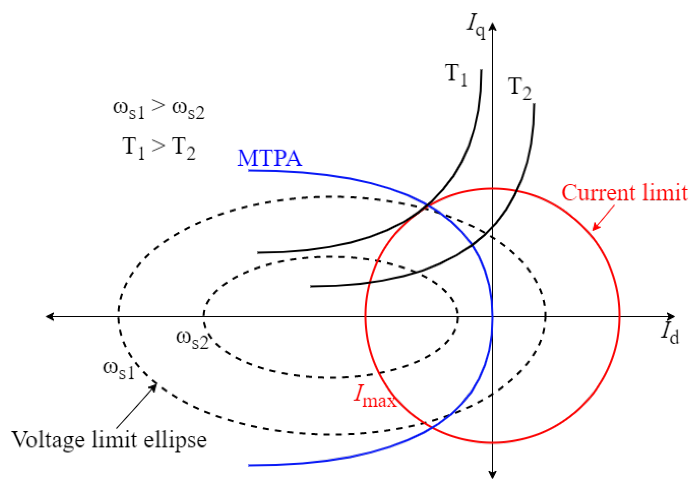
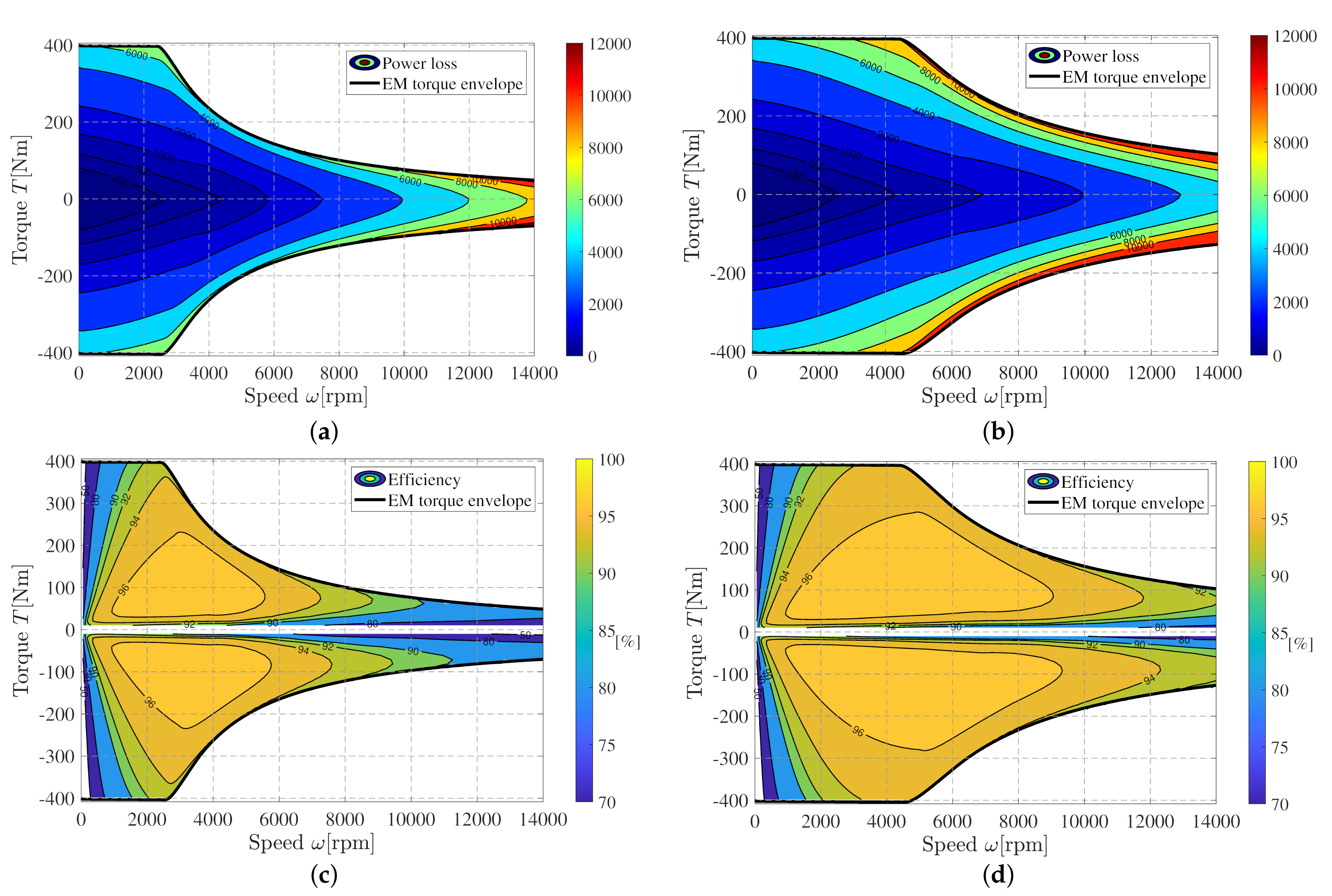
2.1. Electric Machine

The EM used in this study is an interior permanent magnet synchronous machine (IPMSM), as shown in Figure 2. The main parameters of the IPMSM are listed in Table 1, given a 350 V DC-link voltage.
Figure 2. Illustration of IPMSM used in this study.
Table 1. IPMSM parameters at a 350 V DC-link voltage.
For IPMSMs, the widely utilized maximum-torque-per-ampere (MTPA) control strategy enables the delivery of specific torques at a certain speed while minimizing the current usage, which in turn cuts down on the copper loss in the EM. This strategy, however, is subjected to the supplied DC voltage, as illustrated in Figure 3. In the d- and q-axis current ( I d I q ) plane, the voltage limit imposed by the DC voltage supplied is represented as an ellipse. The corresponding speed, also denoted as base speed ( ω s ), marks the highest speed at which the motor can maintain the MTPA strategy and adhere to the voltage constraint. When operating beyond the base speed, the field weakening strategy is employed by injecting the negative I d to reduce the rotor flux. This allows for higher speeds within voltage constraints but results in increased motor losses and reduced torque output, as the motor operates outside its optimal MTPA range.
Figure 3. Illustration of maximum-torque-per-ampere (MTPA) control strategy.
With the higher supplied DC voltage, the ellipse in the I d I q plane becomes larger, and the corresponding base speed also increases. This expansion allows the MTPA area to cover a broader speed range. Within the confines of the voltage constraint and MTPA area, the I d and I q currents remain relatively unaffected by changes in DC voltage. Consequently, copper loss stays constant despite variations in the supplied DC voltage.
To address the non-linearity of IPMSMs and accurately represent losses, such as AC copper loss and iron loss, finite element analysis (FEA) simulations are employed to calculate the EM losses and the corresponding d- and q-axis reference currents for the MTPA control strategy. The calculations consider a range of supplied DC voltages, spanning from 250 V to 450 V . 250 V and 450 V values act as lower and upper boundaries for the DC-link voltage in this study, which are further discussed in Section 3.1.2. The resulting loss data and d- and q-axis reference currents are stored in a three-dimensional map, with the EM speed, EM torque, and DC-link voltage as reference points. Figure 4 provides an example of the EM loss and corresponding efficiency maps when EM is supplied with 250 V and 450 V DC voltages, respectively.
Figure 4. Voltage-variant characteristic EM maps: (a) Power loss with 250 V DC-link voltage, (b) power loss with 450 V DC-link voltage, (c) efficiency with 250 V DC-link voltage, and (d) efficiency with 450 V DC-link voltage.

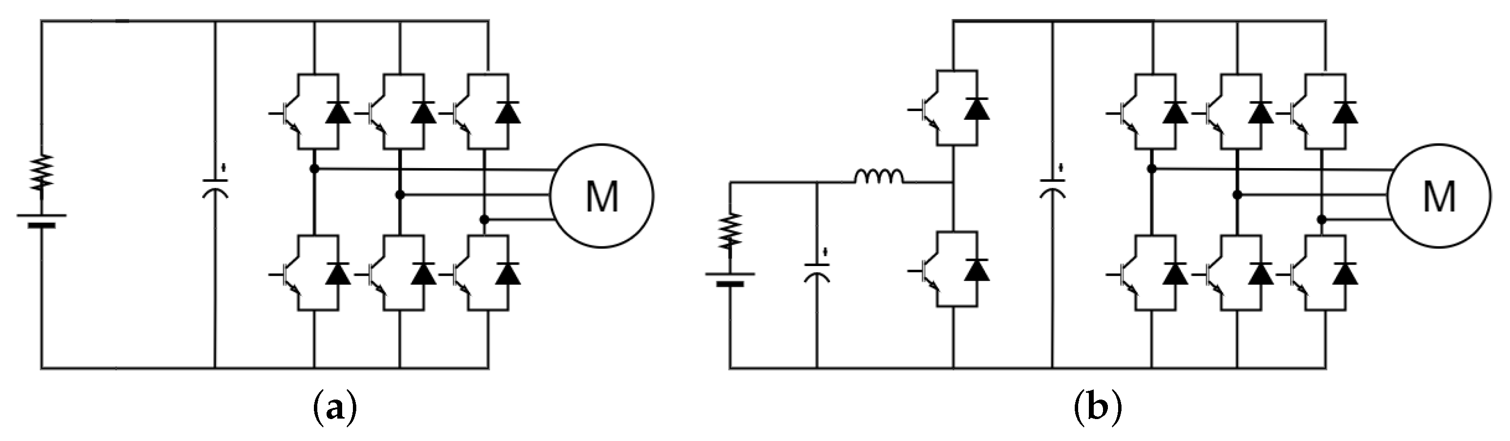
2.2. Three-Phase Inverter

Since the operating points of the EM for the investigated drive cycle, discussed in Section 4, are far below the nominal power rating of the inverter, the junction temperatures of the transistors and diodes change only slightly over the drive cycle. Thus, for simplicity, the effect of temperature variation on the losses is omitted in the analytical loss model of the inverter as well as the DC-DC converter described in Section 2.3, and the parameters used for transistors and diodes are obtained at a constant junction temperature of 65 ° C .
The losses of the IGBT-based three-phase inverter comprise conduction and switching losses of both the insulated gate bipolar transistors (IGBTs) and their anti-parallel diodes, which can be analytically calculated with the following equation [31,32]:
P inv , loss , IGBT = P cond , IGBT + P cond , diode + P sw , IGBT + P sw , diode = 6 V ce 0 I o 1 2 π + M cos φ 8 + 6 r ce I o 2 1 8 + M cos φ 3 π + 6 V d 0 I o 1 2 π M cos φ 8 + 6 r d I o 2 1 8 M cos φ 3 π + 6 ( E on + E off ) f sw I o π I ref V dc U ref 1.3 + 6 E rec f sw I o π I ref V dc U ref 0.6
where V ce 0 is the estimated IGBT forward voltage drop (diode voltage drop behavior from collector to emitter) at zero current, I o is the amplitude of AC phase current, M is the modulation index, cos ϕ is the power factor, r ce is IGBT on-state resistance, V d 0 is the diode forward voltage drop, r d is the diode on-state resistance, V dc is DC-link voltage, f sw is the switching frequency, I ref is the reference current used for linearizing the switching loss, U ref is the reference voltage used for linearizing the switching loss, E on is the transistor turn-on loss, E off is transistor turn-off loss and E rec is the diode reverse recovery energy. The IGBT power module selected for this study is the six-pack FS820R08A6P2B from Infineon (Neubiberg, Germany), with its parameters available in the datasheet.
Compared to IGBT, MOSFETs have a lower current handling capability due to the underdeveloped wafer process technology of MOSFETs and the unavailability of large die sizes for the high current carrying capacity at present [33]. Consequently, in the presented study, two SiC MOSFET CAS300M12BM2 half-bridge modules are connected in parallel for each phase leg. This arrangement ensures the same current rating compared to FS820R08A6P2B and covers the worst operating point of the EM.
Due to the reverse conduction capability of MOSFETs, the MOSFET-based three-phase inverter operates differently during the reverse conduction period depending on the current condition [28,29,34]. For the presented case, the voltage drop across the transistor on-state resistance, r ds , is always smaller than the forward voltage drop of the body diode, V sd 0 , according to
I o · r ds = 325   A · 5.14   m Ω < V sd 0 = 1.76   V
Therefore, it can be assumed that the body diodes of the MOSFETs do not conduct the reverse current during the reverse conduction period; hence, the conduction losses only occur on the transistors. The corresponding three-phase inverter losses can be obtained with the following equation:
P inv , loss , MOSFET = P cond , MOSFET + P sw , MOSFET = 12 1 4 I o 2 2 r ds + 12 ( E on + E off ) f sw I o 2 π I ref V dc U ref 1.4
where r ds is the MOSFET on-state resistance.

2.3. DC-DC Converter
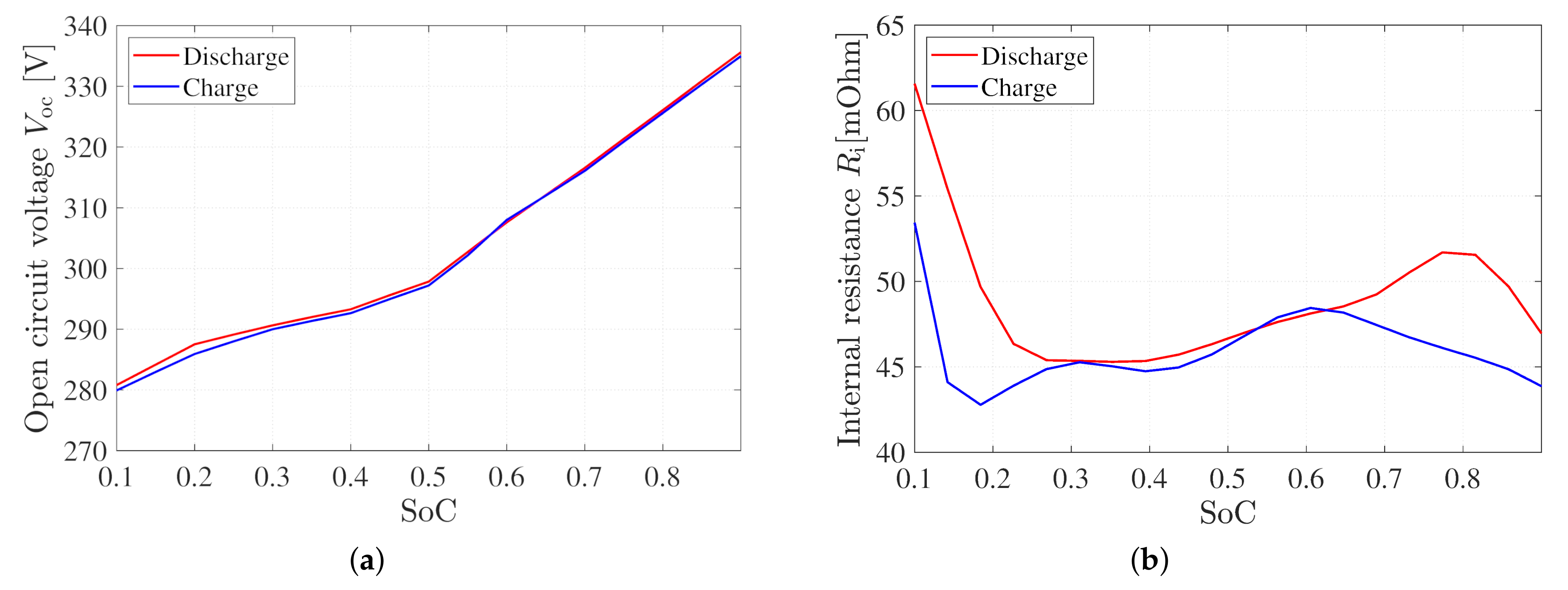
The adjustable DC-link voltage investigated in this study is realized by a bidirectional boost DC-DC converter as already illustrated in Figure 1. This setup enables boost operation from the battery terminals to the DC-link and buck operation from the three-phase inverter to the battery terminal, corresponding to the propulsion and regeneration modes of electric vehicles, respectively.
For an IGBT-based converter, the losses can be calculated analytically as follows:
P DCDC , loss , IGBT = P cond , IGBT + P cond , diode + P sw , IGBT + P sw , diode = V ce 0 I bat + r ce I bat 2 D + V d 0 I bat + r d I bat 2 ( 1 D ) + E sw I bat f sw I ref V dc U ref 1.3 + E rec I bat f sw I ref V dc U ref 0.6
where I bat denotes battery current with the assumption that the amplitude is constant during one pulse period and current fluctuation is filtered by the inductor and D is the duty cycle. The duty cycle D can be calculated as:
D = V bat V dc buck operation 1 V bat V dc boost operation
For a MOSFET-based converter, the losses can be calculated analytically as follows when MOSFETs’ reverse conduction capability is utilized (parallel conduction of diode is neglected according to (2)):
P DCDC , loss , MOSFET = P cond , MOSFET + P sw , MOSFET = r ds I bat 2 + ( E on + E off ) f sw I bat I ref V dc U ref 1.4

2.4. Battery

To keep capturing the dynamic behavior of the battery and the corresponding variations in the terminal output under different operating conditions, the battery is modeled simply as an equivalent electric circuit consisting of an open circuit voltage V oc and an internal resistance R i [35,36,37]. The battery open circuit voltage and internal resistance are dependent on the state of charge as illustrated in Figure 5. Therefore, the battery is only subject to ohmic losses due to the presence of internal battery resistance, which can be described as follows:
P bat , loss = I bat 2 R i
Moreover, the battery terminal voltage can be rewritten as:
V bat = V oc I bat R i
Figure 5. Battery pack data tested under charge and discharge conditions: (a) Open circuit voltage and (b) internal battery resistance relative to the battery SoC.

4. Simulation Results and Discussion

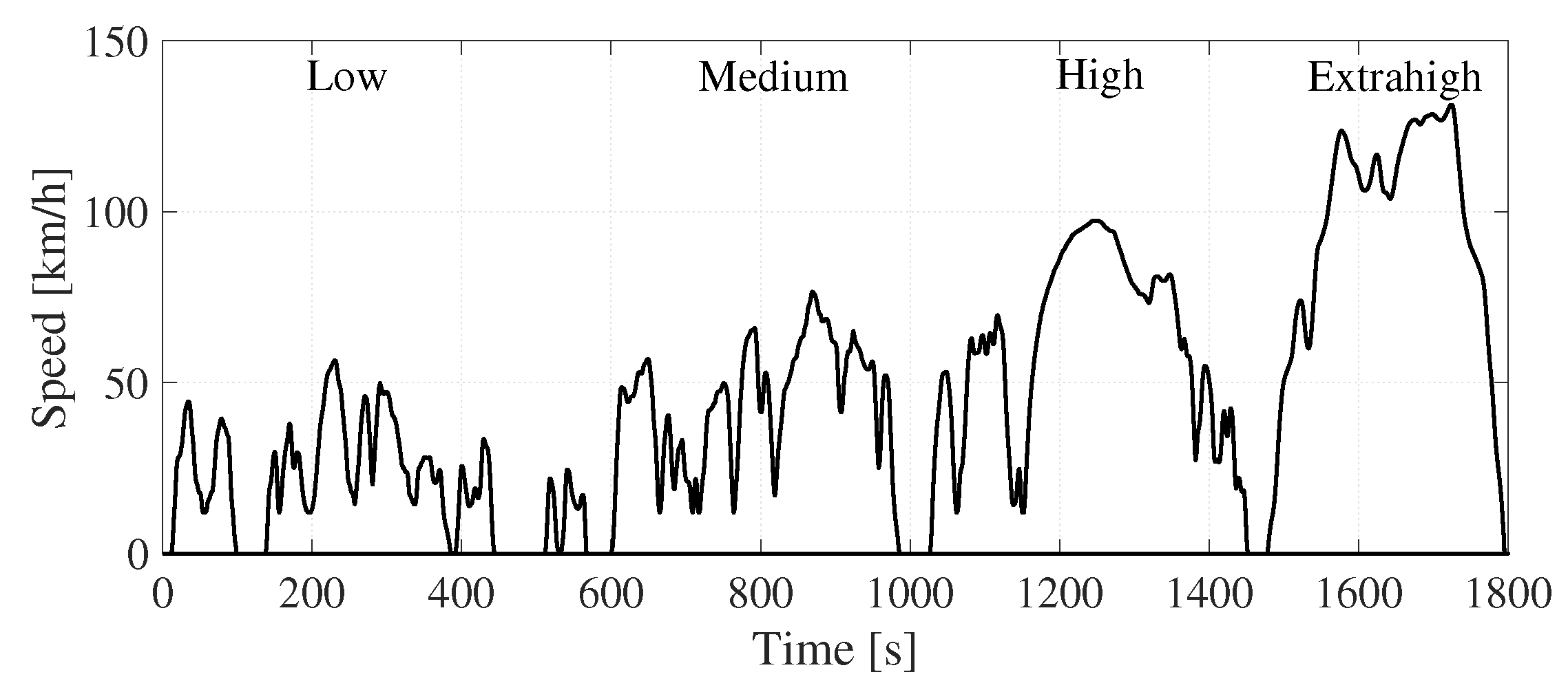
4.1. Drive Cycle Simulation Setup

A complete vehicle and powertrain model, including the detailed power electronics loss models and control, is established in PLECS v4.7 and Simulink v10.7 environment to verify the proposed topologies with optimized DC-link voltage for the adjustable DC-link voltage powertrain. In addition, the DP-based algorithm, achieving an optimized DC-link voltage, is implemented in MATLAB R2023a.
The control structure is shown in Figure 6. The DP optimization block takes vehicle speed information as input and generates optimized, time-sequenced DC-link voltage values. In this study, the complete 1800-s WLTC drive cycle is provided to the DP algorithm prior to the driving mission, allowing it to function as an offline optimization method for obtaining a globally optimal solution. This is because the WLTC drive cycle is a known standard, and the main aim of this paper is to examine the full energy efficiency gain potential of the optimized DC-link voltage. However, if necessary, the DP block can be adapted for online execution over a shorter time horizon, in conjunction with GPS data or velocity prediction algorithms [42,43]. The optimal reference DC-link voltage, V dc * , highlighted with a turquoise line, is then sent to the DC-DC converter controller and field-oriented current controller of the IPMSM. The field-oriented current control scheme, including active damping (marked by the dashed green box) and anti-windup (marked by the dashed green box), is highlighted with blue lines. A description of the parameterization of the control parameters, such as the PI controller gains, can be found in [44]. The measured mechanical system quantities, such as the vehicle speed, v, are highlighted with orange lines.
Figure 6. Schematic illustration of the inverter/PMSM and DC-DC converter control when using an optimized DC link voltage for the WLTC.
The energy efficiency of powertrains is significantly influenced by driving cycles, as demonstrated in previous studies [45,46]. As mentioned before, the Worldwide Harmonized Light Vehicles Test Cycle (WLTC) is utilized as the test scenario in this study, given its comprehensive representation of urban and suburban driving conditions through its low, medium, high, and extra-high-speed sections, as illustrated in Figure 7.
Figure 7. WLTC vehicle speed profile.
To evaluate the efficiency gains provided by the adjustable DC-link voltage powertrain, which employs the optimal DC-link voltage obtained using the proposed optimization method, a baseline powertrain without a propulsion DC-DC converter is also simulated. Consequently, four distinct topologies are examined: (1) Baseline powertrain with an IGBT-based inverter, (2) adjustable DC-link voltage powertrain with IGBT-based DC-DC converter and inverter, (3) baseline powertrain with a MOSFET-based inverter, and (4) adjustable DC-link voltage powertrain with MOSFET-based DC-DC converter and inverter.
It is worth noting that the battery’s open circuit voltage can exhibit substantial variation, as shown in Figure 5a. This variation affects the battery terminal voltage during drive cycle operation, potentially leading to varying energy efficiencies for both baseline and adjustable DC-link voltage powertrains. To assess the impact of battery terminal voltage deviations resulting from different states of charge (SoC) on powertrain energy efficiency, initial battery SoC values of 20% and 80% are investigated in the simulations, representing low and high SoC scenarios.

4.2. Optimized DC-Link Voltage

The optimized DC-link voltage trajectories for the adjustable DC-link voltage powertrain from DP calculation and the DC-link voltage (battery terminal voltage) for the baseline powertrain are depicted in Figure 8. In addition, the corresponding powertrain component instantaneous loss power over the WLTC cycle for low battery SoC case is illustrated in Figure 9.
Figure 8. Optimized DC-link voltage in adjustable DC-link voltage powertrain compared with DC-link voltage in baseline powertrain: (a) IGBT-based powertrains with low battery SoC, (b) MOSFET-based powertrains with low battery SoC, (c) IGBT-based powertrains with high battery SoC and (d) MOSFET-based powertrains with high battery SoC.
It is observed that in all four cases, the optimal DC-link voltage of the adjustable DC-link voltage powertrain remains relatively low and is generally close to the battery terminal voltage during low-speed operating conditions. This outcome is anticipated because when the vehicle operates at a low speed that results in the EM running below its base speed at the given battery terminal voltage (e.g., below 28 km/h at 280 V), the EM loss is insensitive to the DC-link voltage. Meanwhile, the current remains low enough that the power electronics’ switching losses become more dominant, which can be minimized by employing a lower DC-link voltage.
Figure 9. Simulated powertrain component loss power during the WLTC with 20% initial SoC: (a) DC-DC converter loss in IGBT-based powertrains, (b) DC-DC converter loss in MOSFET-based powertrains, (c) inverter loss in IGBT-based powertrains, (d) inverter loss in MOSFET-based powertrains, (e) EM loss in IGBT-based powertrains and (f) EM loss in MOSFET-based powertrains.
Conversely, in high-speed and extra-high-speed operating conditions, the optimal DC-link voltages for both IGBT and MOSFET-based adjustable DC-link voltage powertrains reach the upper boundary. It is observed that even when the battery SoC is at a higher level, resulting in a higher terminal voltage, it is still insufficient for the powertrain to operate at optimal efficiency. This occurs because, in high and extra-high-speed operations with significant current demand, the conduction losses in the EM winding and power electronics become more dominant than the switching losses of the power electronics. As a result, it is preferable to boost the DC-link voltage as high as possible.
On the other hand, during medium-speed operating conditions, the selection of the DC-link voltage becomes crucial for the powertrain’s energy efficiency from a system perspective. This is because the magnitude of the switching losses in the power electronics is comparable to the conduction losses in the power electronics and the EM. Consequently, the IGBT-based adjustable DC-link powertrain exhibits different optimal DC-link voltages than the MOSFET-based powertrain, as the trade-off among the loss components largely depends on the characteristics of the chosen MOSFETs and IGBTs. Furthermore, it is worth noting that a smaller DC-link voltage boosting ratio is required for cases with a higher battery state of charge (SoC), as a higher battery terminal voltage is involved.

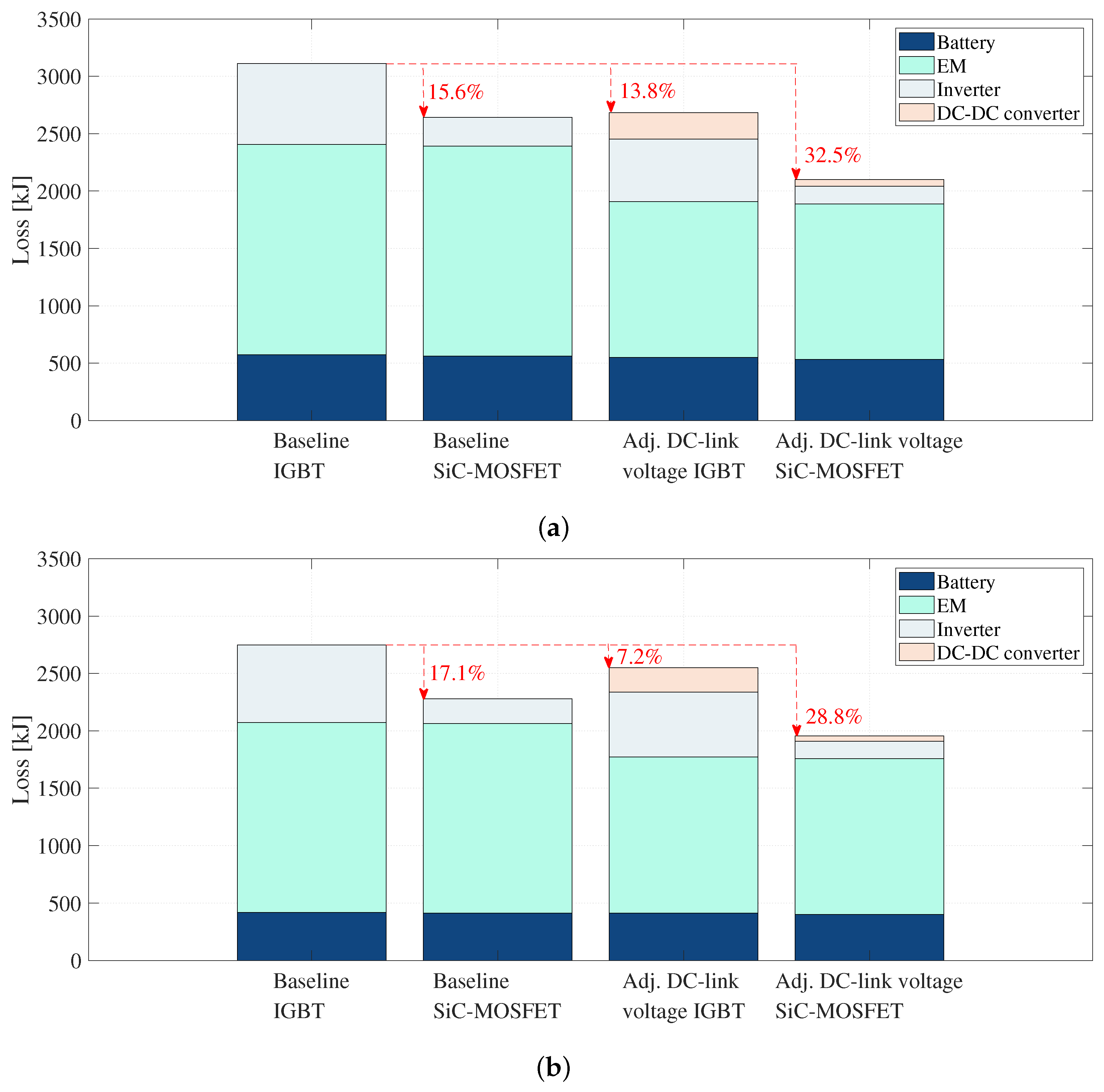
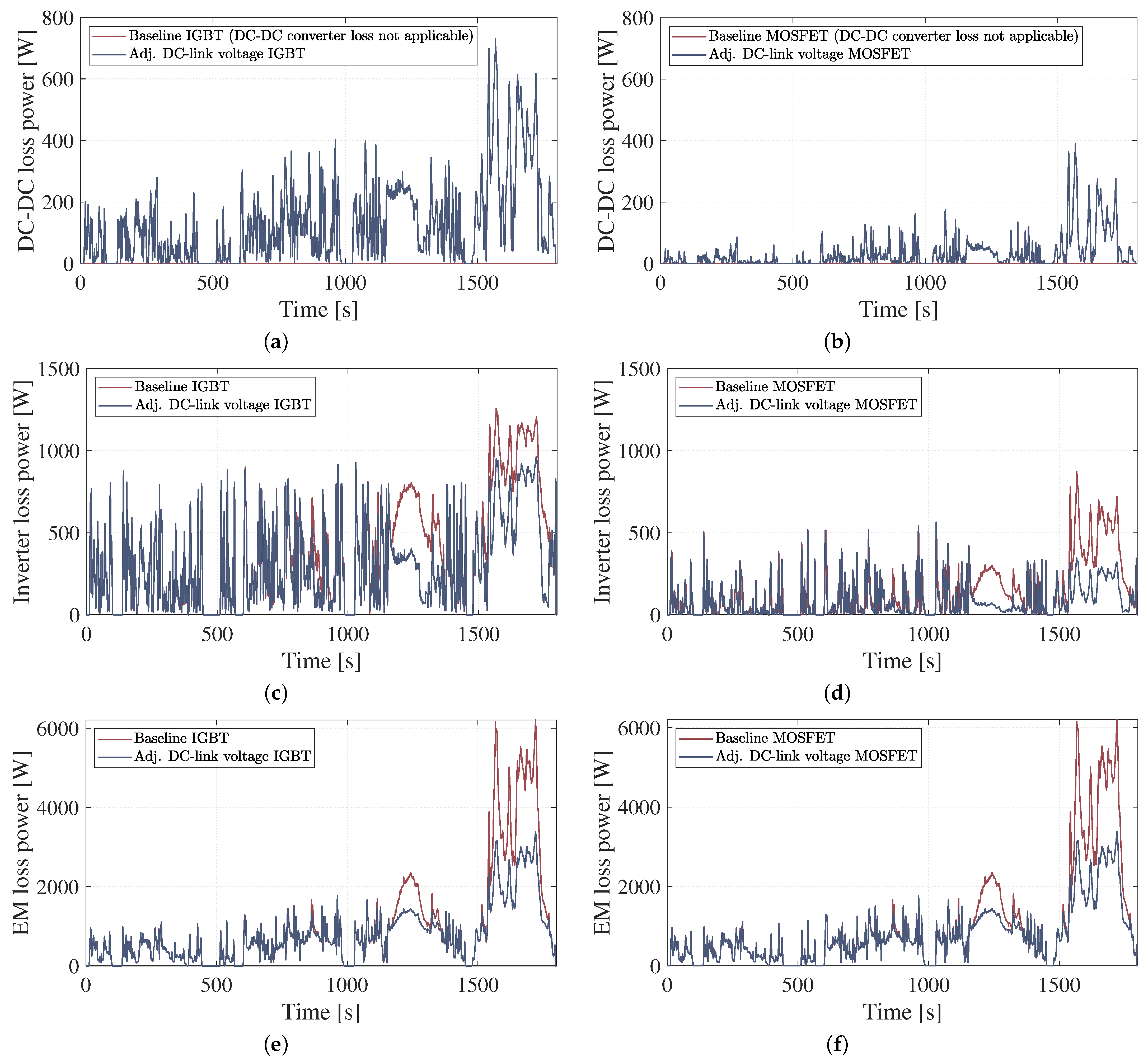
4.3. Energy Consumption and Breakdown of Energy Losses

The simulation results, including the drive cycle energy consumption and the individual powertrain component losses, are summarized in Table 4 and illustrated in Figure 10.
Table 4. Summary of the energy consumption and powertrain component losses obtained from simulations.
The comparison between the baseline and adjustable powertrains, as well as the IGBT and MOSFET powertrains, reveals that when the battery has a low state of charge (SoC), adopting MOSFETs for the inverter in baseline powertrains results in a significant decrease in energy consumption over the WLTC cycle by around 2.8% for both low and high battery SoC levels. As reported in [26,34], MOSFETs achieve, on average, three times lower inverter losses. The energy consumption in IGBT-based powertrains is reduced by 2.51% with optimized DC-link voltage. Although the energy efficiency gain is significant in IGBT-based powertrains with adjustable DC-link voltage, this energy consumption reduction gain is further increased to 3.25% when it comes to MOSFET-based powertrains.
When considering high battery SoC levels, this trend remains the same. However, the efficiency improvement is slightly less compared to low battery SoC levels when adopting adjustable DC-link voltage. This is because baseline powertrains with high battery SoC already result in better powertrain efficiency, mainly due to large loss reductions in EMs and batteries with higher battery terminal voltages, as shown in Figure 10. Nevertheless, adjustable DC-link voltage powertrains still provide significant energy consumption reductions compared to baseline powertrains, with improvements of 1.16% to 1.92% for IGBT and MOSFET respectively.
Regarding the impact of battery SoC, when it drops from 80% to 20%, the energy consumption decreases by around 2.1% for both IGBT-based and MOSFET-based baseline powertrains. However, this energy efficiency deterioration due to battery SoC levels is mitigated when using adjustable DC-link voltage powertrains. The deterioration percentage decreases to around 0.8% for adjustable DC-link voltage powertrains, making the powertrain efficiency less sensitive to battery SoC. This implies that another advantage of the adjustable DC-link voltage powertrain is its ability to maintain similar energy efficiency regardless of battery SoC compared to baseline powertrains.
Figure 10. Powertrain losses obtained for the WLTC considering the battery, EM, inverter, and DC-DC converter losses of the different powertrain configurations: (a) Low battery SoC and (b) high battery SoC.
Upon examining Figure 10, it can be observed that the battery losses are similar for each case with the same battery SoC level. However, with a higher battery SoC, the higher open-circuit voltage results in a lower current, given a similar power level drawn from the battery. Consequently, this leads to a reduction in both the current and ohmic losses of the battery. Between the baseline powertrain and the adjustable DC-link voltage powertrain, the main contribution to the powertrain energy efficiency improvement comes from the EM loss reduction and a slight reduction in inverter losses, which outweighs the additional loss brought by the DC-DC converter. However, in the IGBT-based adjustable DC-link voltage powertrain, the additional DC-DC converter loss still constitutes a significant part of the powertrain losses. On the other hand, when MOSFETs are used in the adjustable DC-link powertrain, the same improved EM efficiency can be achieved as in the IGBT-based adjustable DC-link powertrain, but with much lower losses on the power electronics. The additional DC-DC converter losses are almost negligible, fully utilizing the energy-saving potential of the adjustable DC-link voltage powertrain while mitigating unwanted DC-DC converter losses.

5. Conclusions

This study investigated the potential for improving the energy efficiency of an adjustable DC-link voltage powertrain incorporated with a regular DC-DC boost converter. The utilization of a DC-link voltage adjustment during vehicle operation reduces the overall powertrain losses. The study proposed a DP-based optimization method that considers battery voltage variation during drive cycle operations. The study also assessed the impact of IGBTs and MOSFETs on the energy-saving potential of the adjustable DC-link voltage powertrain. The energy efficiency improvement of the adjustable DC-link voltage powertrain with the optimized DC-link voltage from the proposed optimization method was verified through simulations carried out in PLECS and MATLAB/Simulink software.
The simulation results demonstrate significant energy efficiency improvements for both IGBT-based and MOSFET-based adjustable DC-link voltage powertrains compared to the reference IGBT-based and MOSFET-based powertrains. At high battery SoC levels, the total energy consumption is reduced by 1.16% and 1.92% over the WLTC cycle, respectively. However, when considering low battery SoC levels, the energy consumption reductions are even more substantial, with improvements reaching up to 2.51% and 3.25%, respectively. These findings indicate that the benefits of adjustable DC-link voltage in improving powertrain energy efficiency are further amplified when MOSFETs are adopted, building on the already observed improvements in baseline powertrains with MOSFET in comparison to IGBTs. The main drivers behind this efficiency improvement are the reductions in the EM and inverter losses. Moreover, the additional DC-DC converter loss is almost negligible when MOSFETs are used, which maximizes the energy-saving potential of adjustable DC-link voltage powertrains.

Author Contributions

Conceptualization, Y.X.; methodology, Y.X. and A.K.; software, Y.X. and A.K.; validation, S.K. and A.K.; formal analysis, Y.X.; investigation, Y.X.; data curation, Y.X.; writing—original draft preparation, Y.X.; writing—review and editing, A.K., S.K. and D.S.; visualization, Y.X.; supervision, S.K. and D.S. All authors have read and agreed to the published version of the manuscript.

Funding

This research was funded by the Swedish Energy Agency Program for Vehicle Research and Innovation (FFI), grant number 51459-1.

Data Availability Statement

The data presented in this study are available upon request from the corresponding author. The data are not publicly available due to corporate confidentiality requirements.

Conflicts of Interest

The authors declare no conflict of interest.

Appendix A

Table A1. Coefficients of polynomial equations for solving battery currents.
TransistorOperationabcd
IGBTPropulsion boost I ref · R i · r d I ref · R i · r ce I ref · V oc · r ce + I ref · R i · V d 0 I ref · V oc · r d I ref · V dc · r ce I ref · R i · V dc I ref · R i · V ce 0 I ref · V dc · V oc + I ref · V ce 0 · V oc E sw · V dc · f sw · V dc U ref 1.3 E rec · V dc · f sw · V dc U ref 0.6 I ref · V d 0 · V oc I ref · V ce 0 · V dc I ref · P dc · V dc
Regeneration buck I ref · R i · r ce I ref · R i · r d I ref · V oc · r d + I ref · R i · V d I ref · V dc · r d I ref · V oc · r ce I ref · R i · V dc I ref · R i · V ce 0 E sw · V dc · f sw · V dc U ref 1.3 + E rec · V dc · f sw · V dc U ref 0.6 + I ref · V d 0 · V dc + I ref · V oc · V dc + I ref · V oc · V ce 0 I ref · V oc · V d 0
I ref · P dc · V dc
MOSFETPropulsion boost- r ds 2 · E sw · f sw I ref · V dc U ref 1.4 P dc V oc · R i
Regeneration buck- r ds + R i V oc 2 · E sw · f sw I ref · V dc U ref 1.4 P dc

References

  1. Rietmann, N.; Hügler, B.; Lieven, T. Forecasting the trajectory of electric vehicle sales and the consequences for worldwide CO2 emissions. J. Clean. Prod. 2020, 261, 121038. [Google Scholar] [CrossRef]
  2. Nogueira, T.; Sousa, E.; Alves, G.R. Electric vehicles growth until 2030: Impact on the distribution network power. Energy Rep. 2022, 8, 145–152. [Google Scholar] [CrossRef]
  3. Buberger, J.; Kersten, A.; Kuder, M.; Eckerle, R.; Weyh, T.; Thiringer, T. Total CO2-equivalent life-cycle emissions from commercially available passenger cars. Renew. Sustain. Energy Rev. 2022, 159, 112158. [Google Scholar] [CrossRef]
  4. Sanguesa, J.A.; Torres-Sanz, V.; Garrido, P.; Martinez, F.J.; Marquez-Barja, J.M. A review on electric vehicles: Technologies and challenges. Smart Cities 2021, 4, 372–404. [Google Scholar] [CrossRef]
  5. Karki, A.; Phuyal, S.; Tuladhar, D.; Basnet, S.; Shrestha, B.P. Status of pure electric vehicle power train technology and future prospects. Appl. Syst. Innov. 2020, 3, 35. [Google Scholar] [CrossRef]
  6. Ghasemi-Marzbali, A.; Shafiei, M. Fast-charging station for electric vehicles, challenges and issues: A comprehensive review. J. Energy Storage 2022, 49, 104136. [Google Scholar]
  7. Deng, J.; Bae, C.; Denlinger, A.; Miller, T. Electric vehicles batteries: Requirements and challenges. Joule 2020, 4, 511–515. [Google Scholar] [CrossRef]
  8. Lee, J.H.; Won, C.Y.; Lee, B.K.; Kim, H.B.; Baek, J.H.; Han, K.B.; Chung, U.I. IPMSM torque control method considering DC-link voltage variation and friction torque for EV/HEV applications. In Proceedings of the 2012 IEEE Vehicle Power and Propulsion Conference, Seoul, Republic of Korea, 9–12 October 2012; IEEE: Piscataway, NJ, USA, 2012; pp. 1063–1069. [Google Scholar]
  9. Lee, J.H.; Lee, J.H.; Park, J.H.; Won, C.Y. Field-weakening strategy in condition of DC-link voltage variation using on electric vehicle of IPMSM. In Proceedings of the 2011 International Conference on Electrical Machines and Systems, Beijing, China, 20–23 August 2011; IEEE: Piscataway, NJ, USA, 2011; pp. 1–6. [Google Scholar]
  10. Zhao, N.; Schofield, N.; Niu, W. Energy storage system for a port crane hybrid power-train. IEEE Trans. Transp. Electrif. 2016, 2, 480–492. [Google Scholar] [CrossRef]
  11. Sewergin, A.; Wienhausen, A.H.; Oberdieck, K.; De Doncker, R.W. Modular bidirectional full-SiC DC-DC converter for automotive applications. In Proceedings of the 2017 IEEE 12th International Conference on Power Electronics and Drive Systems (PEDS), Honolulu, HI, USA, 12–15 December 2017; IEEE: Piscataway, NJ, USA, 2017; pp. 277–281. [Google Scholar]
  12. Kok, D.; Morris, A.; Knowles, M. Novel EV drive train topology—A review of the current topologies and proposal for a model for improved drivability. In Proceedings of the 2013 15th European Conference on Power Electronics and Applications (EPE), Lille, France, 2–6 September 2013; IEEE: Piscataway, NJ, USA, 2013; pp. 1–10. [Google Scholar]
  13. Zhao, N.; Schofield, N.; Yang, R.; Gu, R. Investigation of DC-link voltage and temperature variations on EV traction system design. IEEE Trans. Ind. Appl. 2017, 53, 3707–3718. [Google Scholar] [CrossRef]
  14. Muta, K.; Yamazaki, M.; Tokieda, J. Development of new-generation hybrid system THS II-Drastic improvement of power performance and fuel economy. In Proceedings of the SAE 2004 World Congress & Exhibition, Detroit, MI, USA, 8–11 March 2004. SAE Technical Report. [Google Scholar]
  15. Burress, T.A.; Campbell, S.L.; Coomer, C.; Ayers, C.W.; Wereszczak, A.A.; Cunningham, J.P.; Marlino, L.D.; Seiber, L.E.; Lin, H.T. Evaluation of the 2010 Toyota Prius Hybrid Synergy Drive System; Technical Report; Oak Ridge National Lab (ORNL): Oak Ridge, TN, USA, 2011. [Google Scholar]
  16. Staunton, R.H.; Ayers, C.W.; Marlino, L.; Chiasson, J.; Burress, B. Evaluation of 2004 Toyota Prius Hybrid Electric Drive System; Technical Report; Oak Ridge National Lab (ORNL): Oak Ridge, TN, USA, 2006. [Google Scholar]
  17. Yamamoto, K.; Shinohara, K.; Makishima, H. Comparison between flux weakening and PWM inverter with voltage booster for permanent magnet synchronous motor drive. In Proceedings of the Power Conversion Conference-Osaka (Cat. No. 02TH8579), Osaka, Japan, 2–5 April 2002; IEEE: Piscataway, NJ, USA, 2002; Volume 1, pp. 161–166. [Google Scholar]
  18. Yamamoto, K.; Shinohara, K.; Nagahama, T. Characteristics of permanent-magnet synchronous motor driven by PWM inverter with voltage booster. IEEE Trans. Ind. Appl. 2004, 40, 1145–1152. [Google Scholar] [CrossRef]
  19. Yu, C.Y.; Tamura, J.; Lorenz, R.D. Optimum DC bus voltage analysis and calculation method for inverters/motors with variable DC bus voltage. IEEE Trans. Ind. Appl. 2013, 49, 2619–2627. [Google Scholar] [CrossRef]
  20. Lemmens, J.; Driesen, J.; Vanassche, P. Dynamic DC-link voltage adaptation for thermal management of traction drives. In Proceedings of the 2013 IEEE Energy Conversion Congress and Exposition, Denver, CO, USA, 15–19 September 2013; IEEE: Piscataway, NJ, USA, 2013; pp. 180–187. [Google Scholar]
  21. Estima, J.O.; Cardoso, A.J.M. Efficiency analysis of drive train topologies applied to electric/hybrid vehicles. IEEE Trans. Veh. Technol. 2012, 61, 1021–1031. [Google Scholar] [CrossRef]
  22. Prabhakar, K.K.; Ramesh, M.; Dalal, A.; Reddy, C.U.; Singh, A.K.; Kumar, P. Efficiency investigation for electric vehicle powertrain with variable DC-link bus voltage. In Proceedings of the IECON 2016—42nd Annual Conference of the IEEE Industrial Electronics Society, Florence, Italy, 24–27 October 2016; IEEE: Piscataway, NJ, USA, 2016; pp. 1796–1801. [Google Scholar]
  23. Sridharan, S.; Krein, P.T. Optimizing variable DC link voltage for an induction motor drive under dynamic conditions. In Proceedings of the 2015 IEEE Transportation Electrification Conference and Expo (ITEC), Dearborn, MI, USA, 14–17 June 2015; IEEE: Piscataway, NJ, USA, 2015; pp. 1–6. [Google Scholar]
  24. Tenner, S.; Gimther, S.; Hofmann, W. Loss minimization of electric drive systems using a DC/DC converter and an optimized battery voltage in automotive applications. In Proceedings of the 2011 IEEE Vehicle Power and Propulsion Conference, Chicago, IL, USA, 6–9 September 2011; IEEE: Piscataway, NJ, USA, 2011; pp. 1–7. [Google Scholar]
  25. Kumar, K.; Bertoluzzo, M.; Buja, G. Impact of SiC MOSFET traction inverters on compact-class electric car range. In Proceedings of the 2014 IEEE International Conference on Power Electronics, Drives and Energy Systems (PEDES), Mumbai, India, 16–19 December 2014; IEEE: Piscataway, NJ, USA, 2014; pp. 1–6. [Google Scholar]
  26. Nisch, A.; Klöffer, C.; Weigold, J.; Wondrak, W.; Schweikert, C.; Beaurenaut, L. Effects of a SiC TMOSFET tractions inverters on the electric vehicle drivetrain. In Proceedings of the PCIM Europe 2018, VDE International Exhibition and Conference for Power Electronics, Intelligent Motion, Renewable Energy and Energy Management, Nuremberg, Germany, 5–7 June 2018; pp. 1–8. [Google Scholar]
  27. Rahimo, M.; Canales, F.; Minamisawa, R.A.; Papadopoulos, C.; Vemulapati, U.; Mihaila, A.; Kicin, S.; Drofenik, U. Characterization of a silicon IGBT and silicon carbide MOSFET cross-switch hybrid. IEEE Trans. Power Electron. 2015, 30, 4638–4642. [Google Scholar] [CrossRef]
  28. Jiang, D.; Burgos, R.; Wang, F.; Boroyevich, D. Temperature-dependent characteristics of SiC devices: Performance evaluation and loss calculation. IEEE Trans. Power Electron. 2011, 27, 1013–1024. [Google Scholar] [CrossRef]
  29. Acquaviva, A.; Rodionov, A.; Kersten, A.; Thiringer, T.; Liu, Y. Analytical conduction loss calculation of a mosfet three-phase inverter accounting for the reverse conduction and the blanking time. IEEE Trans. Ind. Electron. 2020, 68, 6682–6691. [Google Scholar] [CrossRef]
  30. Kersten, A.; Grunditz, E.; Thiringer, T. Efficiency of active three-level and five-level npc inverters compared to a two-level inverter in a vehicle. In Proceedings of the 2018 20th European Conference on Power Electronics and Applications (EPE’18 ECCE Europe), Riga, Latvia, 17–21 September 2018; IEEE: Piscataway, NJ, USA, 2018; p. P–1. [Google Scholar]
  31. Bierhoff, M.H.; Fuchs, F.W. Semiconductor losses in voltage source and current source IGBT converters based on analytical derivation. In Proceedings of the 2004 IEEE 35th Annual Power Electronics Specialists Conference (IEEE Cat. No. 04CH37551), Aachen, Germany, 20–25 June 2004; IEEE: Piscataway, NJ, USA, 2004; Volume 4, pp. 2836–2842. [Google Scholar]
  32. Zhu, Y.; Xiao, M.; Su, X.; Yang, G.; Lu, K.; Wu, Z. Modeling of conduction and switching losses for IGBT and FWD based on SVPWM in automobile electric drives. Appl. Sci. 2020, 10, 4539. [Google Scholar] [CrossRef]
  33. Yin, S.; Tseng, K.J.; Simanjorang, R.; Tu, P. Experimental comparison of high-speed gate driver design for 1.2-kV/120-A Si IGBT and SiC MOSFET modules. IET Power Electron. 2017, 10, 979–986. [Google Scholar] [CrossRef]
  34. Amirpour, S.; Thiringer, T.; Hagstedt, D. Energy Loss Analysis in a SiC/IGBT Propulsion Inverter over Drive Cycles Considering Blanking time, MOSFET’s Reverse Conduction and the Effect of Thermal Feedback. In Proceedings of the 2020 IEEE Energy Conversion Congress and Exposition (ECCE), Detroit, MI, USA, 11–15 October 2020; IEEE: Piscataway, NJ, USA, 2020; pp. 1505–1511. [Google Scholar]
  35. Lai, X.; Wang, S.; Ma, S.; Xie, J.; Zheng, Y. Parameter sensitivity analysis and simplification of equivalent circuit model for the state of charge of lithium-ion batteries. Electrochim. Acta 2020, 330, 135239. [Google Scholar] [CrossRef]
  36. Estaller, J.; Kersten, A.; Kuder, M.; Mashayekh, A.; Buberger, J.; Thiringer, T.; Eckerle, R.; Weyh, T. Battery impedance modeling and comprehensive comparisons of state-of-the-art cylindrical 18650 battery cells considering cells’ price, impedance, specific energy and c-rate. In Proceedings of the 2021 IEEE International Conference on Environment and Electrical Engineering and 2021 IEEE Industrial and Commercial Power Systems Europe (EEEIC/I&CPS Europe), Bari, Italy, 7–10 September 2021; IEEE: Piscataway, NJ, USA, 2021; pp. 1–8. [Google Scholar]
  37. Estaller, J.; Kersten, A.; Kuder, M.; Thiringer, T.; Eckerle, R.; Weyh, T. Overview of Battery Impedance Modeling Including Detailed State-of-the-Art Cylindrical 18650 Lithium-Ion Battery Cell Comparisons. Energies 2022, 15, 3822. [Google Scholar] [CrossRef]
  38. Du, C.; Huang, S.; Jiang, Y.; Wu, D.; Li, Y. Optimization of energy management strategy for fuel cell hybrid electric vehicles based on dynamic programming. Energies 2022, 15, 4325. [Google Scholar] [CrossRef]
  39. Maino, C.; Misul, D.; Musa, A.; Spessa, E. Optimal mesh discretization of the dynamic programming for hybrid electric vehicles. Appl. Energy 2021, 292, 116920. [Google Scholar] [CrossRef]
  40. Dou, H.; Zhang, Y.; Fan, L. Design of optimized energy management strategy for all-wheel-drive electric vehicles. Appl. Sci. 2021, 11, 8218. [Google Scholar] [CrossRef]
  41. Naseri, F.; Schaltz, E.; Stroe, D.I.; Gismero, A.; Farjah, E. An enhanced equivalent circuit model with real-time parameter identification for battery state-of-charge estimation. IEEE Trans. Ind. Electron. 2021, 69, 3743–3751. [Google Scholar] [CrossRef]
  42. Themann, P.; Eckstein, L. Prediction of driver behaviour by situational models in a cooperative environment to optimize energy efficiency. In Proceedings of the 9th ITS European Congress, Dublin, Ireland, 4–7 June 2013. [Google Scholar]
  43. Zhu, Z.; Gupta, S.; Pivaro, N.; Deshpande, S.R.; Canova, M. A GPU implementation of a look-ahead optimal controller for eco-driving based on dynamic programming. In Proceedings of the 2021 European Control Conference (ECC), Rotterdam, The Netherlands, 29 June–2 July 2021; IEEE: Piscataway, NJ, USA, 2021; pp. 899–904. [Google Scholar]
  44. Kersten, A.; Oberdieck, K.; Bubert, A.; Neubert, M.; Grunditz, E.A.; Thiringer, T.; De Doncker, R.W. Fault detection and localization for limp home functionality of three-level NPC inverters with connected neutral point for electric vehicles. IEEE Trans. Transp. Electrif. 2019, 5, 416–432. [Google Scholar] [CrossRef]
  45. Zaccardi, J.M.; Le Berr, F. Analysis and choice of representative drive cycles for light duty vehicles–case study for electric vehicles. Proc. Inst. Mech. Eng. Part D J. Automob. Eng. 2013, 227, 605–616. [Google Scholar] [CrossRef]
  46. Semon, A.; Crăciunescu, A. Study to Increase the Efficiency of the Electric Drive System of a Vehicle at Different Speeds. In Proceedings of the 2019 11th International Symposium on Advanced Topics in Electrical Engineering (ATEE), Bucharest, Romania, 28–30 March 2019; IEEE: Piscataway, NJ, USA, 2019; pp. 1–7. [Google Scholar]
Disclaimer/Publisher’s Note: The statements, opinions and data contained in all publications are solely those of the individual author(s) and contributor(s) and not of MDPI and/or the editor(s). MDPI and/or the editor(s) disclaim responsibility for any injury to people or property resulting from any ideas, methods, instructions or products referred to in the content.

Article Metrics

Citations

Article Access Statistics

Multiple requests from the same IP address are counted as one view.