Article

Facile Synthesizing Yolk-Shelled Fe3O4@Carbon Nanocavities with Balanced Physiochemical Synergism as Efficient Hosts for High-Performance Lithium–Sulfur Batteries

1
Beijing Key Laboratory of Environmental Science and Engineering, School of Materials Science and Engineering, Beijing Institute of Technology, Beijing 100081, China
2
Beijing Institute of Technology Chongqing Innovation Center, Chongqing 401120, China
3
School of Advanced Manufacturing Engineering, Hefei University, Hefei 230601, China
*
Authors to whom correspondence should be addressed.
Batteries 2023, 9(6), 295; https://doi.org/10.3390/batteries9060295
Submission received: 31 March 2023 / Revised: 26 May 2023 / Accepted: 26 May 2023 / Published: 29 May 2023

Abstract

:
The severe “shuttle effect” of dissolved polysulfide intermediates and the poor electronic conductivity of sulfur cathodes cause capacity decay of lithium–sulfur batteries and impede their commercialization. Herein, we synthesized a series of well-designed yolk-shelled Fe3O4@carbon (YS-Fe3O4@C) nanocavities with different proportions of Fe3O4 as efficient sulfur hosts to stabilize polysulfide intermediates. The yolk-shelled nanocavity architectures were prepared through a facile method, which could effectively confine the active materials and achieve high conductivity. The polysulfide intermediate shuttle was successfully suppressed by a physiochemical synergism effect combining the retention of carbon shells and the adsorption of Fe3O4 nanoparticle cores. The highly conductive carbon shell provides efficient pathways for fast electron transportation. Meanwhile, the visible evolution of active materials and a reversible electrochemical reaction are revealed by in situ X-ray diffraction. With the balanced merits of enhanced electrical conductivity of carbon shell and optimal adsorption of Fe3O4 cores, the S/YS-27Fe3O4@C cathode (Fe3O4 accounts for 27 wt% in YS-Fe3O4@C) had the best electrochemical performance, exhibiting a high reversible specific capacity of 731.9 mAh g−1 and long cycle performance at 1 C (capacity fading rate of 0.03% over 200 cycles).

1. Introduction

Rechargeable lithium–sulfur (Li-S) batteries possess various advantages, including a high theoretical energy density (2600 Wh kg−1 pairing with optimal quantity of lithium anode), low cost, and being environmentally friendly, which are essential and favorable for energy storage [1,2]. However, the commercialization of Li-S batteries is hindered due to some intractable problems. The tough obstruction originates from the multi-electron reaction in the Li-S battery system, owing to complicated phase transformation and multi-step transfer processes [3,4]. The major issues are the poor electrical conductivity and inert solubility of active materials. The insoluble nature and insulation of sulfur and Li2S2/Li2S (5 × 10⁻³⁰ S cm−1 and 10−14 S cm−1, respectively, at 25 °C) result in their deposition propensity, further leading to the passivated material interfaces and sluggish reaction kinetics [5]. In addition, the notorious shuttle effects caused by the dissolution and migration of lithium polysulfide intermediates (Li2S4–Li2S8) contribute to rapid capacity degradation and low coulombic efficiency of Li-S batteries [6]. The shuttle effects not only lead to active material loss but also bring about side reactions on the lithium anode that accelerate the lithium dendrite growth [7].
Tremendous efforts have been made to overcome the abovementioned issues, such as construction of a high-performance cathode, protection for the lithium anode, and modification on the separator [8,9,10]. It is worthwhile to note that the Li2S4 to Li2S conversion process plays a pivotal role, to which close attention has been paid by major previous research works because this conversion process provides three-quarters of the theoretical capacity [11]. However, the high recoverable capacity of Li-S batteries relies heavily on unhindered electron access for mediators [11,12]. The active materials and intermediates are not good conductors naturally; therefore, improving electrical conductivity of the host material is one of the most effective tactics to compensate for the inadequate electronic conductivity of active materials and mediators, which can favor sulfur utilization, especially at high rates. Meanwhile, the dissolved polysulfide intermediates (LiPSs) in the organic electrolyte are easily migrational from the sulfur cathode to the lithium anode, resulting in irreversible deposition and low coulombic efficiency. Thus, the host materials also should be equipped with a strong affinity ability for LiPSs, especially in long-term cycling.
Carbonaceous materials with high conductivity are common host materials [13,14]. Previous studies reported various carbon matrixes that were applied in Li-S batteries with the merits of abundant pore structure, tunable surface properties, and large pore volume [15,16]. Nevertheless, because of the weak Vander Waals interaction between the nonpolar carbon and LiPSs, the soluble LiPSs still dissolve and shuttle in the electrolyte, especially under a high concentration gradient [17]. In order to address this issue, modified strategies were proposed; for instance, functional groups were introduced to host matrixes. The functional groups included hydrophilic heteroatoms sites (N, O, B, and F) [18,19,20], polar inorganic compounds (metal oxides, phosphides, sulfides, nitrides, and carbides) [21,22,23,24], and multi-functional polymers (-COOH, -OH, and -NH2) [25], which all could confine the diffusion of intermediate LiPSs via their strong polar–polar chemical interaction with LiPSs [26]. In particular, transitional metal compounds performed outstandingly as LiPS anchors and redox reaction activators [27,28]. For instance, Zhao and colleagues [29] reported on the yolk–shell ZnO structure (YS-ZnO) that exhibited strong anchoring ability towards LiPSs, allowing for both chemical adsorption and physical confinement of the LiPSs. As a result, the S/YS-ZnO-based Li-S battery achieved a high initial specific capacity of 1355 mAh g−1 and outstanding capacity retention of approximately 89.44% after 500 cycles at 0.5 C. However, most transitional metal compounds have poor electrical conductivity inherently, which is unqualified for the fast electron transfer requirement of sulfur redox kinetics upon cycling [30,31]. Therefore, multi-functional electrodes, simultaneously possessing high electrical conductivity and strong LiPS adsorption, are urgently needed to develop high-performance Li-S batteries.
Herein, in order to enhance the conductivity of sulfur cathode and suppress the shuttle effects comprehensively, a series of yolk-shelled ferroferric oxide @ carbon nanocavities (YS-Fe3O4@C) were constructed as sulfur hosts for Li-S batteries. The carbon shells formed in situ as the reaction chamber, on the one hand, provide a conductive network for the electron, and on the other hand, they encapsulate the insulating active materials, thus effectively alleviating the shuttle effects. Synchronously, the Fe3O4 cores as LiPS absorbers mitigate the shuttle effects, achieving the reversible conversion of LiPS. The yolk-shelled structure ensures excellent conductivity and LiPS confinement effectively through the physiochemical synergism effect. On the basis of balanced electrical conductivity and suitable adsorption, the YS-27Fe3O4@C with optimal Fe3O4 core content delivered high reversible capacity and remarkable cycling stability.

2. Materials and Methods

2.1. Synthesis of Fe3O4@C Nanoparticles

Ferric nitrate hydrate (Fe(NO3)3·9H2O) and benzene-1,3,5-tricarboxylic acid (C6H3(COOH)3, H3BTC) ethanolic solution were mixed rapidly in a molar ratio of 3:2. The metal–organic coordination gel (Fe-BTC) was formed immediately and aged for 24 h. To remove the nonreacted molecules, solvent exchange was applied with ethanol and distilled water repeatedly. To obtain Fe3O4@C nanoparticles, the purified gel was firstly dried by freeze-drying, then carbonized in an argon atmosphere at 800 °C for 5 h with a heating rate of 5 °C min−1.

2.2. Fabrication of yolk-shelled YS-Fe3O4@C Nanocavities

The obtained Fe3O4@C nanoparticles were etched with hydrochloric acid (HCl) solution; etching time was accurately controlled to adjust the removed quantity of Fe3O4. After etching, the products were recollected by filtration. The collected products of yolk-shelled Fe3O4@C nanocavities (YS-Fe3O4@C) were washed with deionized water and ethanol in sequence and dried thoroughly at 60 °C.

2.3. Sulfur Cathode Preparation

The S/Fe3O4@C and S/YS-Fe3O4@C composites were prepared through a modified melt–diffusion method. The sulfur power (65 wt%) was ground with the prepared Fe3O4@C (35 wt%) or YS-Fe3O4@C (35 wt%) in a quartz mortar. The mixture was sealed in a vessel that was filled with argon gas, followed by heating at 155 °C for 12 h and then at 220 °C for 30 min to evaporate the residual sulfur. The composites S/Fe3O4@C and S/YS-Fe3O4@C were obtained after the mixtures were cooled down to room temperature. The actual sulfur content was determined by Thermal gravimetric analysis (TGA) test. As-prepared active materials (S/Fe3O4@C or S/YS-Fe3O4@C), acetylene black (AB), and polyvinylidene difluoride (PVDF) binder in the ratio of 7:2:1 were blended and ball-milled in N-methyl-2-pyrrolidone (NMP) solvent to form a uniform slurry. Then, the slurry was coated onto the aluminum foil evenly and dried at 60 °C for 24 h. The electrodes were punched into circular slices with a diameter of 11 mm. The sulfur loading of the sulfur cathode was calculated at 0.8 ± 0.1 mg cm−2. The high-loading sulfur cathode was prepared using sulfur powders and the S/YS-27Fe3O4@C at a mass ratio of mS:mC = 7:3.

2.4. Materials Characterization

The morphologies of Fe3O4@C and YS-Fe3O4@C were characterized by scanning electron microscopy (SEM) and high-angle annular dark-field scanning transmission electron microscopy (HADDF-STEM) using FEI Quanta 250 and JEM-2100 instruments, respectively. X-ray diffraction (XRD) patterns were measured by Rigaku UltimaIV-185 instrument with CuKα radiation at a scan speed of 8 degree per min from 10° to 90°. The specific surface areas were examined by Micromeritics (ASAP 2460) and analyzed by the Brunauer–Emmett–Teller (BET) method. The TGA measurements were conducted to determine the Fe3O4 and sulfur content using a thermal analyzer (6200 EXSTAR, Tokyo, Japan) under air and argon atmosphere with a ramp rate of 10 °C per min. The chemical element composition was identified by X-ray photoelectron spectroscopy (XPS) analysis using Thermo esca lab 250Xi instrument, Waltham, MA, USA. The resistances of Fe3O4@C and YS-Fe3O4@C were recorded with the aid of an automatic powder resistivity analyzer (PD-600, Tokyo, Japan). In situ XRD measurement was determined by a Brucker (Mannheim, Germany) XRD system during the discharge and charge between 1.7 and 2.8 V at 0.1 C. A stainless-steel Swagelok-type cell was assembled using S/YS-27Fe3O4@C cathode with 4 mg cm−2 sulfur loading.

2.5. Electrochemical Measurement

The 2025-typed coin cells with lithium foils as counter electrodes were assembled in an argon-filled glovebox with both oxygen and water contents less than 1 ppm. Celgard 2400 membranes served as separators. The electrolyte was prepared by dissolving 1 M bis-(trifluoromethane) sulfonamide lithium (LiTFSI) in mixed solution of 1,3-dioxolane (DOL) and 1,2-dimethoxyethane (DME; 1:1 v/v) with 0.2 M LiNO3 as additive. The cycling and rate performance of the coin cells were tested at various current densities with a voltage window from 1.7 to 2.8 V (vs. Li/Li+) using a LAND electrochemical station (CT2001A LAND, Wuhan, China). The electrochemical impedance spectra (EIS) were measured by CHI660E (Shanghai, China) electrochemical workstation with an amplitude of ±5 mV over the frequency range of 0.01 Hz to 100 kHz. The cyclic voltammetry measurements (CV) were performed on a CHI660E between 1.5 V and 3.0 V with a scan rate of 0.1 mV s−1. Additionally, all capacity values were calculated on the basis of elemental sulfur mass.

3. Results and Discussion

A facile and effective method to fabricate a yolk-shelled host material for the sulfur cathode was proposed. Figure 1a diagrams the synthetic process of S/YS-Fe3O4@C composite, which consisted of a sequence of steps, including precursor formation, calcination, etching, and sulfur infusion. Firstly, Fe-BTC gel (Figure S1) was formed rapidly when ferric nitrate hydrate (Fe(NO3)3·9H2O) and benzene-1,3,5-tricarboxylic acid (C6H3(COOH)3, H3BTC) were mixed in ethanolic solution. The Fe3+ ions were linked by the organic bridging ligands of H3BTC, leading to the growth of metal–ligand coordination polymer network (Fe-BTC gel) [32,33]. After removing the residual reagents by solvent exchange, the Fe-BTC gel was transferred to a freeze-dryer, and the dried product (Fe-BTC aerogel) was obtained by freeze-drying for 48 h. The Fe3O4@C composite was finally synthesized by annealing the Fe-BTC aerogel composite in an argon atmosphere at 800 °C for 5 h. The TGA measurement helped to understand what happened during the annealing process, and the TGA showed four weight loss steps in the range of 30–800 °C. Between 30 and 100 °C (Region Ⅰ), an approximate 10% weight loss was attributed to the removal of hydration water. An approximate 10% weight loss during the interval of 100–300 °C (Region Ⅱ) may have been caused by the decomposition of nitrate radical. In Region III (300–390 °C), the carboxyl on the BTC ligand decomposed, contributing to ~20% weight loss. Upon further increase in the temperature (Region Ⅳ, 390–500 °C), the benzene ring was oxidized into COx, corresponding to ~20% weight loss [34,35]. The final residue was iron oxides, with ~40 wt% weight remaining. According to the BET test results (Figures S3 and S4 and Table S1), the Fe3O4@C exhibited a larger specific surface area than Fe-BTC aerogel. Subsequently, the yolk-shelled nanocavities (YS-Fe3O4@C) (Figure 1b) with the different contents of iron core were obtained by etching the Fe3O4@C samples using HCl solution. With proper regulating, the S/YS-Fe3O4@C cathode was expected to facilitate electron transfer and confine LiPS species synergistically.
The morphological and structural information was characterized by SEM and TEM. The microstructures of the Fe3O4@C composites contained carbon frameworks and encapsulated Fe3O4 nanoparticles (Figure 2a,b). As shown in the HADDF-STEM images of Figure 2c, there were three regions with remarkable characters. In the Part d region (Figure 2c), the Fast Fourier Transform (FFT) was identified as the (220) and (222) crystal planes of Fe3O4 (Figure 2(d1)). In the TEM image (Figure 2(d2)), the lattice spacing was measured to be 0.252 nm, which corresponded to the (311) plane of Fe3O4 (PDF #99-0073). The multi-layered crystal layer with a distance of 0.362 nm (Figure 2(e1,e2)) was verified to be graphited carbon, which was formed under the catalysis of the Fe3O4 core [36]. In addition to the crystal carbon shell, the amorphous carbon layer away from the Fe3O4 core was also observed, which may have resulted from the carbonization at high temperature (Figure 2(f1,f2)). The element distribution of Fe, O, and C are clearly demonstrated in Figure 2g. The Fe and O elements were concentrated in the core, while the C elements dispersed in the surroundings, which was assigned to the Fe3O4 core wrapped by carbon.
The crystal structure of as-synthesized Fe3O4@C was analyzed by XRD. In Figure 2h, the sharp peaks at 18.3°, 30.1°, 35.5°, 43.1°, 57.0°, and 62.6° are confirmed to be the (111), (220), (311), (400), (511), and (440) planes of magnetite Fe3O4 (PDF #99-0073), respectively. It is noted that the Fe peak (PDF #99-0064) appeared in the XRD patterns; this phenomenon indicated the high reducibility of carbon during the annealing process that resulted in the partial reduction of Fe3O4 to Fe. The high graphitization degree of carbon was detected in the Raman spectra (Figure 2i). The peaks at 1343 and 1580 cm−1 are assigned to the D and G bands of carbon resulting from disordered carbon and graphitic layers, respectively [31]. The intensity ratio of the D to G band (ID/IG) was 0.92, indicating the high graphitization degree of the Fe3O4@C composite. In addition, the obvious peak at 2694 cm−1 stemmed from the G’ band of carbon, suggesting the formation of a highly graphitized multi-layered carbon [37,38]. The highly graphitized carbon framework formed by the catalysis of Fe3O4 during the carbonization process can enhance the conductivity of the host materials, thus promoting the electrochemical performance of Li-S batteries [39], which will be elaborated upon in the following sections.
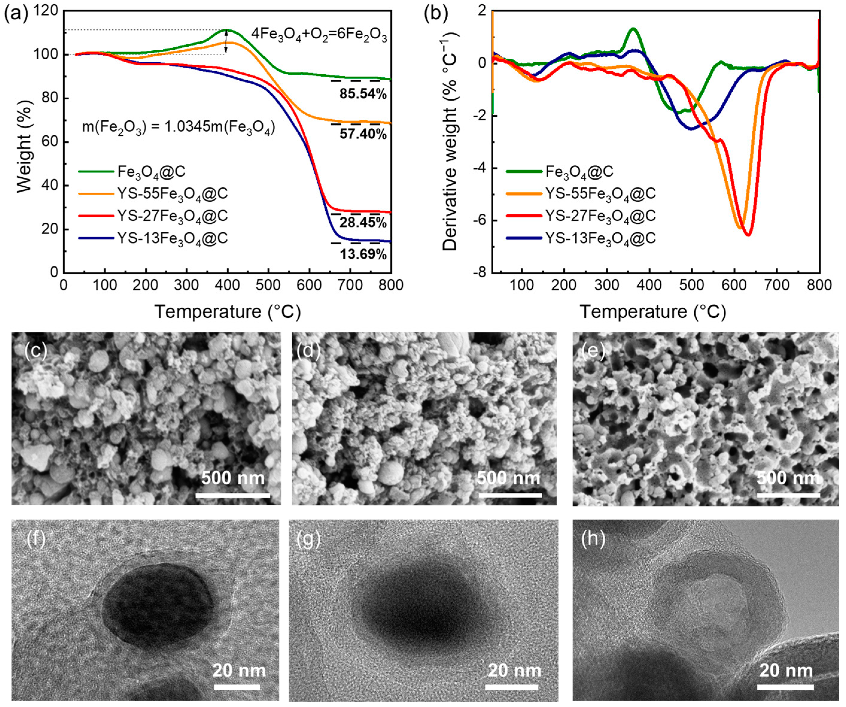
The polar iron oxide could suppress the LiPS shuttle effect; however, the large amounts of Fe3O4 with heavy relative molecular mass would inhibit the cell-level specific energy [40,41,42]. To optimize the sulfur cathode, a succession of yolk-shelled Fe3O4@C nanocavities with different proportions of cores were acquired by controlling the etching time. As shown in Figure 3a, TGA in the air atmosphere was performed to ascertain the Fe3O4 content in Fe3O4@C and YS-Fe3O4@C. There was an obvious weight increment in Fe3O4@C before 400 °C because Fe3O4 was oxidized first to Fe2O3 [43]. The Fe3O4 content was calculated at approximately 82.69%, 55.49%, 27.50%, and 13.23% after deducting the increased amount of oxygen. According to the content of Fe3O4 core, the yolk-shelled host materials were abbreviated as Fe3O4@C, YS-55Fe3O4@C, YS-27Fe3O4@C, and YS-13Fe3O4@C. In addition, the derivative thermogravimetric (DTG) curves (Figure 3b) show that the thermal stabilities of YS-55Fe3O4@C, YS-27Fe3O4@C, and YS-13Fe3O4@C were better than that of Fe3O4@C, indicating that the thermal stability of host materials was enhanced due to the formation of the yolk-shelled structure. The SEM images exhibit that Fe and Fe3O4 nanoparticles on the carbon framework surface were eroded after the etching process in the HCl solution (Figure 3c–e), and the longer the time that Fe3O4@C was etched by HCl solution, the more noticeable the erosion phenomenon that was observed. The microstructures of YS-55Fe3O4@C, YS-27Fe3O4@C, and YS-13Fe3O4@C were further examined in the TEM images (Figure 3f–h). Consequently, the size of the inner iron core was reduced, and the void space within the architecture was formed after etching; this contributed to a robust yolk-shelled structure. The multi-layer carbon shell can confine soluble long-chain LiPSs inside the carbon sphere, which is beneficial for alleviating the shuttle effect. Moreover, the void space can perform as a reservoir effectively, guaranteeing high loading of sublimed sulfur materials.
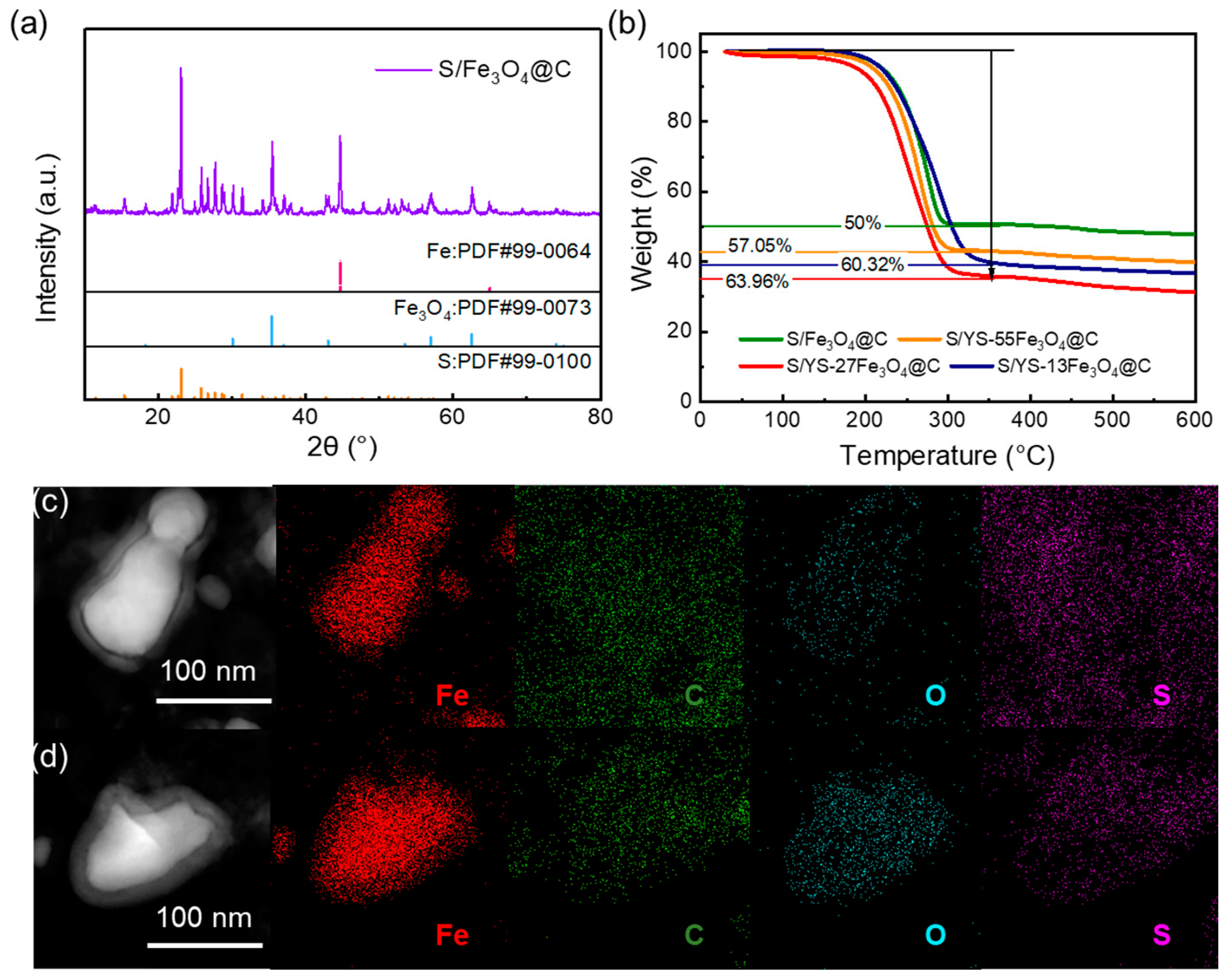
Figure 4a shows the XRD pattern of S/Fe3O4@C. The diffraction peaks of sublimed sulfur can be identified distinctly, confirming the incorporation of sulfur into the host. In the TGA measurement (Figure 4b), the remarkable mass attenuation at 100–350 °C was observed, and the weight percentage of sulfur in S/Fe3O4@C, S/YS-55Fe3O4@C, S/YS-27Fe3O4@C, and S/YS-13Fe3O4@C was calculated to be 50%, 57.05%, 63.96%, and 60.32%, respectively. The high sulfur percentage in S/YS-Fe3O4@C further manifested the advantage of YS-Fe3O4@C as high-performance sulfur cathode. As shown in the EDS mapping results (Figures S5 and Figure 4c,d), the sulfur element was clearly observed to be concentrated in the interior parts of the host materials, and no aggregated sulfur particles were found on the surface of YS-Fe3O4@C under high-resolution imaging. This indicates the successful infiltration of sulfur into the framework of YS-Fe3O4@C, further demonstrating that the yolk-shelled structure is beneficial for efficiently reserving sulfur.
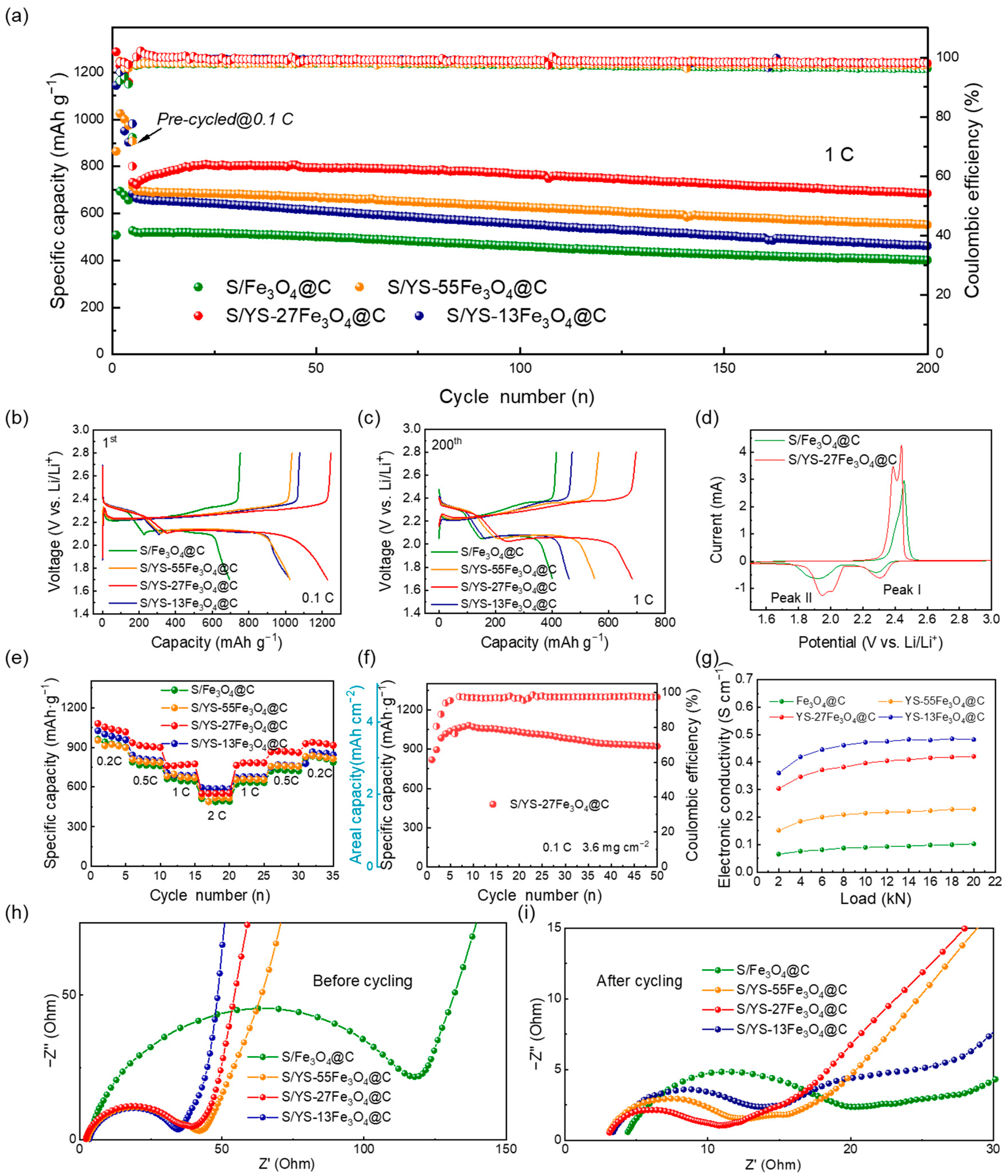
Coin cells with S/C@Fe3O4, S/YS-55Fe3O4@C, S/YS-27Fe3O4@C, and S/YS-13Fe3O4@C cathodes were assembled to verify the advantages of the yolk-shelled structure. The long-term cycling performances of coin cells were evaluated at a current density of 1 C (1 C = 1675 mA g−1) in the potential window of 1.8–2.8 V, and the results are shown in Figure 5a. In the initial activation stage at the current density of 0.1 C, the S/YS-27Fe3O4@C electrode exhibited a higher capacity (1286.2 mAh g−1) than S/C@Fe3O4 (508.2 mAh g−1), S/YS-55Fe3O4@C (863.9 mAh g−1), and S/YS-13Fe3O4@C (1143.9 mAh g−1). In the following cycles at the current density of 1 C, the specific capacity of the S/YS-27Fe3O4@C electrode also obviously surpassed those of the S/Fe3O4@C, S/YS-55Fe3O4@C, and S/YS-13Fe3O4@C electrodes, and the discharge capacities of initial cycles were 731.9, 526.6, 714.6, and 683.4 mAh g−1, respectively, at 1 C. After 200 cycles, the S/YS-27Fe3O4@C electrode maintained the highest discharge capacity of 684.9 mAh g−1, with a capacity retention of 93.6%. In contrast, the discharge capacities of the S/Fe3O4@C, S/YS-55Fe3O4@C, and S/YS-13Fe3O4@C electrodes declined to 401, 551.7, and 461.3 mAh g−1, with capacity retentions of 76.1%, 77.2%, and 67.5%, respectively. The S/YS-13Fe3O4@C electrode performed the worst on capacity retention due to the insufficient content of Fe3O4, as it was difficult to suppress the severe migration of LiPSs. Furthermore, we observed the S/YS-27 Fe3O4@C to have a minor polarization voltage at both 0.1 C and 1 C in the galvanostatic discharge/charge curves, even after 200 cycles (Figure 5b,c). In comparison, the S/Fe3O4@C cathodes exhibited larger potential gaps between the charge plateau and discharge plateau, which resulted in higher polarizations.
The electrochemical mechanism of Fe3O4@C cathodes was investigated by the CV measurements at the scan rate of 0.1 mV s−1 in the cut-off potential range between 1.5 V and 3.0 V. The CV curves are shown in Figure 5d: during the cathodic scan, the first reduction peak (Peak I) is ascribed to the reduction of S8 to long-chain soluble Li2Sx (4 ≤ x ≤ 8); the second reduction peak (Peak II) indicates a further reduction of Li2Sx to insoluble Li2S2/Li2S; during the anodic scan, the oxidation peak at ~2.42 V is associated with the reversible oxidation of Li2S2/Li2S to LiPSs and, ultimately, to S8 [41]. In comparison with the S/Fe3O4@C, the S/YS-27Fe3O4@C exhibited a positive shift for the cathode peaks and a slight negative shift for the anodic peak after the initial cycle, evidencing that the polarization of S/YS-27Fe3O4@C was inhibited effectively [42]. These results are well in line with the discharge/charge voltage profiles. Moreover, the higher peak current densities and larger closed-loop area of S/YS-27Fe3O4@C manifested the high capacity and the enhanced reaction kinetics [7,22]. The shoulder peaks that appeared on the S/YS-27Fe3O4@C curve also indicated that the yolk-shelled structure was attributed to the fast conversion of LiPSs. Furthermore, CV curves of the S/YS-27Fe3O4@C and Fe3O4@C cathodes of the successive three cycles (Figure S6) exhibited intensities of the anodic and cathodic peaks that are highly overlapped, which manifests remarkable electrochemistry reversibility.
To explore the reversible capacities and recoverable capability of S/Fe3O4@C, S/YS-55Fe3O4@C, S/YS-27Fe3O4@C, and S/YS-13Fe3O4@C, the rate performances of Li-S batteries employed with corresponding cathode materials were tested (Figure 5e). The S/YS-27Fe3O4@C electrode performed the best, with discharge capacities of 1080.0, 934.3, 760.4, and 552 mAh g−1 at 0.2, 0.5, 1, and 2 C, respectively. When the current density returned to 0.2 C, the discharge capacity of S/YS-27Fe3O4@C electrode rebounded to 928.1 mAh g−1, revealing prominent reversibility and superior stability. In comparison, Fe3O4@C, S/YS-55Fe3O4@C, and S/YS-13Fe3O4@C electrodes showed obviously deteriorated discharge capacities of 818.7, 830.7, and 778.3 mAh g−1, respectively, when the current density went back to 0.2 C. In addition, the S/YS-27Fe3O4@C electrode still had superior cycling stability at a high current rate (2 C) (Figure S7). The initial reversible capacity of S/YS-27Fe3O4@C electrode was 602 mAh g−1 at 2 C and retained 549.9 mAh g−1 after 180 cycles, with the ultralow decay rate and the outstanding coulombic efficiency approaching 100%. A high-loading sulfur cathode (S/YS-27Fe3O4@C) with a loading of 3.6 mg cm−2 was investigated (Figure 5f). This cathode demonstrated high discharge capacities of 1082.6 mAh g−1 and reversible capacities of 923.1 mAh g−1 after 50 cycles at 0.1 C. The S content was determined to be 66.67% by TGA, as illustrated in Figure S8. Additionally, the S/YS-27Fe3O4@C exhibited high initial areal capacities of 2.12 mAh cm−2 at 1 C for sulfur loadings of 3.01 mg cm−2 (Figure S9). The results confirm the potential of S/YS-27Fe3O4@C cathode for use in high-energy–density Li-S batteries.
It is noted that the S/YS-13Fe3O4@C cathode exhibited an initial specific capacity of 595.6 mAh g−1 at 2 C, which was even higher than that of the S/YS-27Fe3O4@C electrode. According to previous work [41], a charging overpotential is generally required to excite the conversion of Li2S to solid S8 in typical Li-S batteries owing to the natural inertness, especially at high current density. Therefore, high electrical conductivity is also necessary to compensate for the inadequate electronic conductivity of the active materials [34]. The electrical conductivity of the host material was evaluated using a four-point probe method under different forces (Figure 5g). It was found that YS-Fe3O4@C exhibited superior electrical conductivity compared with Fe3O4@C, with the order being YS-13Fe3O4@C > YS-27Fe3O4@C > YS-55Fe3O4@C. This indicated that the electronic conductivity of the material increased as excess Fe3O4 was etched away and the yolk–shell structure was formed. In addition, the EIS measurement was conducted to investigate the conductivity of four electrodes, and the Nyquist plots of EIS are illustrated in Figure 5h,i. The semicircle at high frequencies is associated with the charge–transfer resistance (Rct), which reflects the electrochemical activity of the electrode. The inclined slope in the low-frequency region is attributed to a Warburg diffusion process (W), which represents the ion diffusion in electrodes. The S/YS-Fe3O4@C electrode exhibited smaller charge–transfer resistance than the S/Fe3O4@C electrode, demonstrating the enhanced electrochemical kinetics of yolk-shelled cathodes. The yolk-shelled cathodes showed diminished Rct in the order of S/YS-13Fe3O4@C < S/YS-27Fe3O4@C < S/YS-55Fe3O4@C < Fe3O4@C, suggesting that the reinforced charge–transfer capability to facilitate the rate performance upon accommodating more liquid electrolytes due to void space. Compared with the initial EIS spectrum, the resistances, especially the S/YS-27Fe3O4@C, decreased significantly after five cycles at 0.1 C. That is because the yolk-shelled structure with a 27wt% content of Fe3O4 core established continuous and percolating transport for Li+ and electrons, which contributed to the activation process [44].
To further explore the absorbed capability of Fe3O4, the electrochemical performance of S/YS-27Fe3O4@C and S/YS-13Fe3O4@C at different temperature conditions were measured, and the results are shown in Figure S10a. The discharge capacities of S/YS-27Fe3O4@C retained 855.8, 898.3, 892.8, and 884.2 mAh g−1 at 25, 35, 40, and 45 °C after 10 cycles, which were higher than those of S/YS-13Fe3O4@C (808.5, 874.7, 867.6, and 860.6 mAh g−1 at 25, 35, 40, and 45 °C after 10 cycles). In addition, even after 45 cycles at 0 °C, the S/YS-27Fe3O4@C (81.23%) exhibited higher capacity retention than S/YS-13Fe3O4@C (69.59%) (Figure S10b), demonstrating its extraordinary cycling stability. High temperature could exacerbate the shuttle effect and accelerate the dissolution of LiPSs into electrolytes [45]; accordingly, the cells were also tested at 55 °C (Figure S10c) to examine the electrochemical performance of the yolk-shelled structure at high temperature. The S/YS-27Fe3O4@C cathode delivered an initial discharge capacity of 740.9 mAh g−1 and a fading capacity rate of 0.62% per cycle over 80 cycles at 0.5 C. The fading capacity rate of S/YS-27Fe3O4@C was lower than that of S/YS-13Fe3O4@C (0.77% per cycle at 0.5 C). Therefore, the improved cycling stability enhanced by Fe3O4 was demonstrated clearly, especially under wide-temperature conditions. The confinement capability of Fe3O4 for LiPSs contributed to this advantage.
XPS was further carried out to investigate the chemical interaction between Fe3O4 and LiPSs. The XPS of Fe 2p spectra were measured before and after cycling (Figure 6a,b). After cycling, the peaks of Fe 2p 1/2 and Fe 2p 3/2 shifted to lower binding energy, indicating the strong interaction between Fe3O4 and LiPSs, which could trigger electron transfer from the electronegative Sn2− to Fe3O4 [22,46]. Thus, the electron density around the Fe atoms was improved, which further introduced lower binding energy. According to previous studies [12,47], this conversion of long-chain LiPSs to thiosulfate is reversible and beneficial to the electrochemical performance because both the thiosulfate and polythionate complex can serve as mediators to restrain LiPS dissolution. Therefore, by decreasing the Fe oxidation state, the conversion at the initial discharge stage could be realized, further transitioning to polythionate complexes and short-chain LiPSs [47]. The peaks around 707 eV could be assigned to the formation of Fe-S chemical bonds after the molten sulfur load in Fe3O4@C. The peak intensity decline after cycling indicates the decrease of the Fe-S compounds after cycling [48]. The reversibility of Fe-S demonstrated that the active material (sulfur) could take part in the reaction reversibly, thus enhancing the sulfur’s electrochemical utilization. In the S 2p spectrum of S/YS-27Fe3O4@C after cycling (Figure S11), the fitting peaks at 162.54 and 163.72 eV correspond to the terminal sulfur (ST−1), and peaks at 164.17 and 165.35 eV are ascribed to bridging sulfur (SB0) in S 2p, respectively [49]. In addition, the S 2p 3/2 peaks between 166 and 171 eV are related to the formation of the polythionate and thiosulfate, respectively, which are attributed as intermediates for sulfur conversion [46,50]. The S 2p result also suggests that the Fe3O4 contributed to the promoted sulfur conversion, which is in accordance with the Fe 2p spectrum.
To investigate the visible evolution of active materials during continuous electrochemical reactions and the mechanism of the role of Fe3O4 in the cathode system, in situ XRD tests were conducted on Li-S cells employing S/YS-27Fe3O4@C. The prototype cell was charged and discharged at 0.1 C, during which diffractions of the signals at different potentials were continuously collected. The evolution of its intensity was plotted with contour plots and is displayed in Figure 6c. Notably, a steady peak of 24.1° was observed throughout the cycle, as shown in the contour plots, indicating that the positive phase was fully irradiated and the signal was received [51]. In a typical Li-S cell, the discharge curve usually presents two potential plateaus, corresponding to the reduction of S8 to soluble LiPSs around 2.33 V and then the reduction of these LiPSs to insoluble Li2S2/Li2S around 2.07 V [52]. During the initial stage of discharge at 23°, a strong Bragg peak corresponding to the crystalline S8 (222) plane was observed, attributed to the formation of Li2S8. The intensity of liquid-phase Li2S6 and Li2S4 was difficult to distinguish until Li2S4 gradually transformed into solid-phase Li2S2 and Li2S. Therefore, at the end of the discharge, a 26.9° Bragg peak was attributed to the insoluble Li2S (111) crystal plane [53], whose peak intensity gradually increased. Obviously, the intensity of the diffraction peak of Fe3O4 (311) near 35.9° changed as the discharging reaction proceeded. When the ramp region started from 2.3 V and the low potential plateau region started from 2.2 V, a weakening of the diffraction peak intensity of Fe3O4 was observed, verifying that the migration of LiPSs to the anode was inhibited by adsorption on the Fe3O4 surface. In the following stage, with the conversion of LiPSs, the diffraction peak intensity of Fe3O4 was restored. This result reflects the reversible interaction between Fe3O4 crystals and LiPSs, providing a reasonable explanation for the long-term cycling performance and improved coulombic efficiency of the S/YS-27Fe3O4@C cell.
Overall, Fe3O4 not only exhibited a strong affinity for LiPSs but also promoted the LiPS conversion process, thereby suppressing the shuttle effect. As the proportion of Fe3O4 decreased, the electronic conductivity of host materials increased; however, the containment effect for LiPSs was significantly reduced. Therefore, S/YS-27Fe3O4@C, which balances strong adsorption and high conductivity, exhibited an ultrahigh capacity retention of 93.6%, fast redox kinetics, and high reversibility, surpassing S/YS-13Fe3O4@C, S/YS-55Fe3O4@C, and Fe3O4@C cathodes.

4. Conclusions

In summary, we rationally regulated a yolk-shelled Fe3O4@carbon nanocavity to balance the electrical conductivity and the adsorption for LiPSs. The well-sophisticated host with an optimal proportion of Fe3O4 could realize a “physical–chemical” dual-barrier for LiPSs, offer an efficient contact area for sulfur, and accommodate the volume expansion. In addition, the highly conductive carbon shell and channel framework accelerated the electron transport and improved the sulfur utilization, especially at high current densities. With the balanced merits of enhanced electrical conductivity of the carbon shell and optimal adsorption of the Fe3O4 cores, the S/YS-27Fe3O4@C cathode had the best electrochemical performance, exhibiting a high reversible specific capacity of 731.9 mAh g−1 and long cycle performance at 1 C (capacity fading rate of 0.03% over 200 cycles). This work will also enlighten future studies on similar structures with conductive components and adsorbent components in host materials.

5. Patents

The patent (ZL 202011311563.4) results from the work are reported in this manuscript.

Supplementary Materials

The following supporting information can be downloaded at: https://www.mdpi.com/article/10.3390/batteries9060295/s1, Figure S1: The optical photograph of Fe-BTC gel; Figure S2: TG curve of FE-BTC aerogel acquired in a nitrogen atmosphere; Figure S3: Nitrogen adsorption/desorption isotherm of FE-BTC aerogel with an inset showing the corresponding size distribution of pores; Figure S4: Nitrogen adsorption/desorption isotherm of Fe3O4@C with an inset showing the corresponding size distribution of pores; Figure S5: EDS elemental mapping images of (a) S/Fe3O4@C, (b) S/YS-55Fe3O4@C, (c) S/YS-27Fe3O4@C, and (d) S/YS-13Fe3O4@C; Figure S6: CV curves of S/YS-27Fe3O4@C and (b) S/Fe3O4@C at 0.1 mV s−1 for different cycles; Figure S7: Long-term cycling stability of S/YS-27Fe3O4@C electrode at 2 C; Figure S8: TGA curves of S/YS-27Fe3O4@C in N2; Figure S9: Cycle performance at 1 C of S/YS-27Fe3O4@C under high sulfur loadings; Figure S10: Cycle performance of S/YS-27Fe3O4@C and S/YS-13Fe3O4@C cathode with a wide temperature range: (a) 25–45 °C, (b) 0 °C, and (c) 55 °C; Figure S11: S 2p in S/YS-27Fe3O4@C after cycling; Table S1: Pore structure parameters of Fe-BTC and Fe3O4@C.

Author Contributions

Conceptualization, F.W. and Y.S.; methodology, Y.L.; validation, L.C. and Y.L.; formal analysis, C.Z. and K.Y.; investigation, L.W. and Z.L.; data curation, Y.B.; writing—original draft preparation, L.C. and C.Z.; writing—review and editing, K.Y.; supervision, X.Y. All authors have read and agreed to the published version of the manuscript.

Funding

This research was funded by the National Natural Science Foundation of China, grant no. 22179008 and 21875022; the Natural Science Foundation of Chongqing, China, grant no. cstc2020jcyj-msxmX0654, cstc2020jcyj-msxmX0589, cstc2021jcyj-msxm1125, and cstc2020jcyj-msxmX0888; and the China Postdoctoral Science Foundation, grant no. 2021M700403.

Data Availability Statement

Not applicable.

Acknowledgments

L. Chen acknowledges the support from the Beijing Institute of Technology Research Fund Program for Young Scholars. K. Yan acknowledges the support from the China Postdoctoral Science Foundation.

Conflicts of Interest

The authors declare no conflict of interest.

References

  1. Bruce, P.G.; Freunberger, S.A.; Hardwick, L.J.; Tarascon, J.-M. Li–O2 and Li–S Batteries with High Energy Storage. Nat. Mater. 2012, 11, 19–29. [Google Scholar] [CrossRef]
  2. Zhang, L.; Wang, Y.; Niu, Z.; Chen, J. Advanced Nanostructured Carbon-Based Materials for Rechargeable Lithium-Sulfur Batteries. Carbon 2019, 141, 400–416. [Google Scholar] [CrossRef]
  3. Borchardt, L.; Oschatz, M.; Kaskel, S. Carbon Materials for Lithium Sulfur Batteries—Ten Critical Questions. Chem. Eur. J. 2016, 22, 7324–7351. [Google Scholar] [CrossRef]
  4. Chung, S.-H.; Chang, C.-H.; Manthiram, A. Progress on the Critical Parameters for Lithium-Sulfur Batteries to Be Practically Viable. Adv. Funct. Mater. 2018, 28, 1801188. [Google Scholar] [CrossRef]
  5. Yuan, H.; Peng, H.-J.; Li, B.-Q.; Xie, J.; Kong, L.; Zhao, M.; Chen, X.; Huang, J.-Q.; Zhang, Q. Conductive and Catalytic Triple-Phase Interfaces Enabling Uniform Nucleation in High-Rate Lithium-Sulfur Batteries. Adv. Energy Mater. 2019, 9, 1802768. [Google Scholar] [CrossRef]
  6. Xu, Z.-L.; Kim, S.J.; Chang, D.; Park, K.-Y.; Dae, K.S.; Dao, K.P.; Yuk, J.M.; Kang, K. Visualization of Regulated Nucleation and Growth of Lithium Sulfides for High Energy Lithium Sulfur Batteries. Energy Environ. Sci. 2019, 12, 3144–3155. [Google Scholar] [CrossRef]
  7. Zhao, Q.; Wang, R.; Wen, J.; Hu, X.; Li, Z.; Li, M.; Pan, F.; Xu, C. Separator Engineering toward Practical Li-S Batteries: Targeted Electrocatalytic Sulfur Conversion, Lithium Plating Regulation, and Thermal Tolerance. Nano Energy 2022, 95, 106982. [Google Scholar] [CrossRef]
  8. Luo, D.; Li, G.; Deng, Y.; Zhang, Z.; Li, J.; Liang, R.; Li, M.; Jiang, Y.; Zhang, W.; Liu, Y.; et al. Synergistic Engineering of Defects and Architecture in Binary Metal Chalcogenide toward Fast and Reliable Lithium–Sulfur Batteries. Adv. Energy Mater. 2019, 9, 1900228. [Google Scholar] [CrossRef]
  9. Li, X.; Zhao, X.; Wang, J.; Chen, C.; Hu, C. A Multifunctional Separator Based on Dilithium Tetraaminophthalocyanine Self-Assembled on RGO with Improved Cathode and Anode Performance in Li–S Batteries. Carbon 2023, 201, 307–317. [Google Scholar] [CrossRef]
  10. Wu, F.; Zhao, S.; Chen, L.; Lu, Y.; Su, Y.; Jia, Y.; Bao, L.; Wang, J.; Chen, S.; Chen, R. Metal-Organic Frameworks Composites Threaded on the CNT Knitted Separator for Suppressing the Shuttle Effect of Lithium Sulfur Batteries. Energy Storage Mater. 2018, 14, 383–391. [Google Scholar] [CrossRef]
  11. Rafie, A.; Kim, J.W.; Sarode, K.K.; Kalra, V. A Review on the Use of Carbonate-Based Electrolytes in Li-S Batteries: A Comprehensive Approach Enabling Solid-Solid Direct Conversion Reaction. Energy Storage Mater. 2022, 50, 197–224. [Google Scholar] [CrossRef]
  12. Guo, D.; Li, X.; Ming, F.; Zhou, Z.; Liu, H.; Hedhili, M.N.; Tung, V.; Alshareef, H.N.; Li, Y.; Lai, Z. Electropolymerization Growth of an Ultrathin, Compact, Conductive and Microporous (UCCM) Polycarbazole Membrane for High Energy Li–S Batteries. Nano Energy 2020, 73, 104769. [Google Scholar] [CrossRef]
  13. Han, Q.; Li, X.; Shi, X.; Zhang, H.; Song, D.; Ding, F.; Zhang, L. Outstanding Cycle Stability and Rate Capabilities of the All-Solid-State Li–S Battery with a Li7P3S11 Glass-Ceramic Electrolyte and a Core–Shell S@BP2000 Nanocomposite. J. Mater. Chem. A 2019, 7, 3895–3902. [Google Scholar] [CrossRef]
  14. Yang, X.; Luo, J.; Sun, X. Towards High-Performance Solid-State Li–S Batteries: From Fundamental Understanding to Engineering Design. Chem. Soc. Rev. 2020, 49, 2140–2195. [Google Scholar] [CrossRef]
  15. Chen, K.; Sun, Z.; Fang, R.; Shi, Y.; Cheng, H.-M.; Li, F. Metal-Organic Frameworks (MOFs)-Derived Nitrogen-Doped Porous Carbon Anchored on Graphene with Multifunctional Effects for Lithium-Sulfur Batteries. Adv. Funct. Mater. 2018, 28, 1707592. [Google Scholar] [CrossRef]
  16. Wang, J.; Jia, L.; Duan, S.; Liu, H.; Xiao, Q.; Li, T.; Fan, H.; Feng, K.; Yang, J.; Wang, Q.; et al. Single Atomic Cobalt Catalyst Significantly Accelerates Lithium Ion Diffusion in High Mass Loading Li 2 S Cathode. Energy Storage Mater. 2020, 28, 375–382. [Google Scholar] [CrossRef]
  17. Zhu, J.; Yang, D.; Yin, Z.; Yan, Q.; Zhang, H. Graphene and Graphene-Based Materials for Energy Storage Applications. Small 2014, 10, 3480–3498. [Google Scholar] [CrossRef]
  18. Wu, F.; Zhao, S.; Chen, L.; Lu, Y.; Su, Y.; Li, J.; Bao, L.; Yao, J.; Zhou, Y.; Chen, R. Electron Bridging Structure Glued Yolk-Shell Hierarchical Porous Carbon/Sulfur Composite for High Performance Li-S Batteries. Electrochim. Acta 2018, 292, 199–207. [Google Scholar] [CrossRef]
  19. Bie, C.; Yu, H.; Cheng, B.; Ho, W.; Fan, J.; Yu, J. Design, Fabrication, and Mechanism of Nitrogen-Doped Graphene-Based Photocatalyst. Adv. Mater. 2021, 26, 2003521. [Google Scholar] [CrossRef]
  20. Yao, W.; Tian, C.; Yang, C.; Xu, J.; Meng, Y.; Manke, I.; Chen, N.; Wu, Z.; Zhan, L.; Wang, Y.; et al. P-Doped NiTe2 with Te-Vacancies in Lithium–Sulfur Batteries Prevents Shuttling and Promotes Polysulfide Conversion. Adv. Mater. 2022, 34, 2106370. [Google Scholar] [CrossRef]
  21. Yuan, H.; Peng, H.-J.; Huang, J.-Q.; Zhang, Q. Sulfur Redox Reactions at Working Interfaces in Lithium-Sulfur Batteries: A Perspective. Adv. Mater. Interfaces 2019, 6, 1802046. [Google Scholar] [CrossRef]
  22. Sun, W.; Liu, C.; Li, Y.; Luo, S.; Liu, S.; Hong, X.; Xie, K.; Liu, Y.; Tan, X.; Zheng, C. Rational Construction of Fe2N@C Yolk–Shell Nanoboxes as Multifunctional Hosts for Ultralong Lithium–Sulfur Batteries. ACS Nano 2019, 13, 12137–12147. [Google Scholar] [CrossRef]
  23. Ai, W.; Li, J.; Du, Z.; Zou, C.; Du, H.; Xu, X.; Chen, Y.; Zhang, H.; Zhao, J.; Li, C.; et al. Dual Confinement of Polysulfides in Boron-Doped Porous Carbon Sphere/Graphene Hybrid for Advanced Li-S Batteries. Nano Res. 2018, 11, 4562–4573. [Google Scholar] [CrossRef]
  24. Liu, X.; Wang, S.; Wang, A.; Wang, Z.; Chen, J.; Zeng, Q.; Chen, P.; Liu, W.; Li, Z.; Zhang, L. A New Cathode Material Synthesized by a Thiol-Modified Metal–Organic Framework (MOF) Covalently Connecting Sulfur for Superior Long-Cycling Stability in Lithium–Sulfur Batteries. J. Mater. Chem. A 2019, 7, 24515–24523. [Google Scholar] [CrossRef]
  25. Lei, T.; Chen, W.; Huang, J.; Yan, C.; Sun, H.; Wang, C.; Zhang, W.; Li, Y.; Xiong, J. Multi-Functional Layered WS2 Nanosheets for Enhancing the Performance of Lithium-Sulfur Batteries. Adv. Energy Mater. 2017, 7, 1601843. [Google Scholar] [CrossRef]
  26. Deng, D.-R.; Xue, F.; Jia, Y.-J.; Ye, J.-C.; Bai, C.-D.; Zheng, M.-S.; Dong, Q.-F. Co4N Nanosheet Assembled Mesoporous Sphere as a Matrix for Ultrahigh Sulfur Content Lithium–Sulfur Batteries. ACS Nano 2017, 11, 6031–6039. [Google Scholar] [CrossRef]
  27. Cao, Z.; Jia, J.; Chen, S.; Li, H.; Sang, M.; Yang, M.; Wang, X.; Yang, S. Integrating Polar and Conductive Fe2O3–Fe3C Interface with Rapid Polysulfide Diffusion and Conversion for High-Performance Lithium–Sulfur Batteries. ACS Appl. Mater. Interfaces 2019, 11, 39772–39781. [Google Scholar] [CrossRef]
  28. Shen, J.; Xu, X.; Liu, J.; Wang, Z.; Zuo, S.; Liu, Z.; Zhang, D.; Liu, J.; Zhu, M. Unraveling the Catalytic Activity of Fe–Based Compounds toward Li2 Sx in Li–S Chemical System from dp Bands. Adv. Energy Mater. 2021, 11, 2100673. [Google Scholar] [CrossRef]
  29. Zhang, R.; Wu, M.; Fan, X.; Jiang, H.; Zhao, T. A Li-S Battery with Ultrahigh Cycling Stability and Enhanced Rate Capability Based on Novel ZnO Yolk-Shell Sulfur Host. J. Energy Chem. 2021, 55, 136–144. [Google Scholar] [CrossRef]
  30. Wang, Z.; Dong, Y.; Li, H.; Zhao, Z.; Bin Wu, H.; Hao, C.; Liu, S.; Qiu, J.; Lou, X.W. Enhancing Lithium–Sulphur Battery Performance by Strongly Binding the Discharge Products on Amino-Functionalized Reduced Graphene Oxide. Nat. Commun. 2014, 5, 5002. [Google Scholar] [CrossRef]
  31. Xu, H.; Jiang, Q.; Zhang, B.; Chen, C.; Lin, Z. Integrating Conductivity, Immobility, and Catalytic Ability into High-N Carbon/Graphene Sheets as an Effective Sulfur Host. Adv. Mater. 2020, 32, 1906357. [Google Scholar] [CrossRef]
  32. Zhu, B.-J.; Yu, X.-Y.; Jia, Y.; Peng, F.-M.; Sun, B.; Zhang, M.-Y.; Luo, T.; Liu, J.-H.; Huang, X.-J. Iron and 1,3,5-Benzenetricarboxylic Metal–Organic Coordination Polymers Prepared by Solvothermal Method and Their Application in Efficient As(V) Removal from Aqueous Solutions. J. Phys. Chem. C 2012, 116, 8601–8607. [Google Scholar] [CrossRef]
  33. Wei, Q.; James, S.L. A Metal–Organic Gel Used as a Template for a Porous Organic Polymer. Chem. Commun. 2005, 12, 1555–1556. [Google Scholar] [CrossRef]
  34. Liu, S. 3D Pomegranate-like Structures of Porous Carbon Microspheres Self-Assembled by Hollow Thin-Walled Highly-Graphitized Nanoballs as Sulfur Immobilizers for Li–S Batteries. Nano Energy 2019, 63, 103894. [Google Scholar] [CrossRef]
  35. Mahmood, A.; Zou, R.; Wang, Q.; Xia, W.; Tabassum, H.; Qiu, B.; Zhao, R. Nanostructured Electrode Materials Derived from Metal–Organic Framework Xerogels for High-Energy-Density Asymmetric Supercapacitor. ACS Appl. Mater. Interfaces 2016, 8, 2148–2157. [Google Scholar] [CrossRef]
  36. Qiao, Z.; Zhang, Y.; Meng, Z.; Xie, Q.; Lin, L.; Zheng, H.; Sa, B.; Lin, J.; Wang, L.; Peng, D. Anchoring Polysulfides and Accelerating Redox Reaction Enabled by Fe-Based Compounds in Lithium–Sulfur Batteries. Adv. Funct. Mater. 2021, 31, 2100970. [Google Scholar] [CrossRef]
  37. Chakrabarti, A.; Lu, J.; Skrabutenas, J.C.; Xu, T.; Xiao, Z.; Maguire, J.A.; Hosmane, N.S. Conversion of Carbon Dioxide to Few-Layer Graphene. J. Mater. Chem. 2011, 3, 9491–9493. [Google Scholar] [CrossRef]
  38. Gao, Z.; Schwab, Y.; Zhang, Y.; Song, N.; Li, X. Ferromagnetic Nanoparticle–Assisted Polysulfide Trapping for Enhanced Lithium–Sulfur Batteries. Adv. Funct. Mater. 2018, 28, 1800563. [Google Scholar] [CrossRef]
  39. Tan, G.; Xu, R.; Xing, Z.; Yuan, Y.; Lu, J.; Wen, J.; Liu, C.; Ma, L.; Zhan, C.; Liu, Q.; et al. Burning Lithium in CS2 for High-Performing Compact Li2S–Graphene Nanocapsules for Li–S Batteries. Nat. Energy 2017, 2, 1–10. [Google Scholar] [CrossRef]
  40. Bhargav, A.; He, J.; Gupta, A.; Manthiram, A. Lithium-Sulfur Batteries: Attaining the Critical Metrics. Joule 2020, 4, 285–291. [Google Scholar] [CrossRef]
  41. He, J.; Luo, L.; Chen, Y.; Manthiram, A. yolk-shelled C@Fe3O4 Nanoboxes as Efficient Sulfur Hosts for High-Performance Lithium–Sulfur Batteries. Adv. Mater. 2017, 29, 1702707. [Google Scholar] [CrossRef]
  42. Liu, G. MOF Derived In-Situ Carbon-Encapsulated Fe3O4@C to Mediate Polysulfides Redox for Ultrastable Lithium-Sulfur Batteries. Chem. Eng. J. 2020, 381, 122652. [Google Scholar] [CrossRef]
  43. Zhang, L.; Wan, F.; Cao, H.; Liu, L.; Wang, Y.; Niu, Z. Integration of Binary Active Sites: Co3V2O8 as Polysulfide Traps and Catalysts for Lithium-Sulfur Battery with Superior Cycling Stability. Small 2020, 16, 1907153. [Google Scholar] [CrossRef] [PubMed]
  44. Guo, J.; Jiang, H.; Yu, M.; Li, X.; Dai, Y.; Zheng, W.; Jiang, X.; He, G. Sandwich-Structured Flexible Interlayer with Co3O4 Nanoboxes Strung along Carbon Nanofibers on Both Sides for Fast Li+ Transport and High Redox Activity in High-Rate Li-S Batteries. Chem. Eng. J. 2022, 449, 137777. [Google Scholar] [CrossRef]
  45. Deng, D.R.; Xue, F.; Bai, C.-D.; Lei, J.; Yuan, R.; Zheng, M.S.; Dong, Q.F. Enhanced Adsorptions to Polysulfides on Graphene-Supported BN Nanosheets with Excellent Li–S Battery Performance in a Wide Temperature Range. ACS Nano 2018, 12, 11120–11129. [Google Scholar] [CrossRef]
  46. Jiang, H.; Liu, X.-C.; Wu, Y.; Shu, Y.; Gong, X.; Ke, F.-S.; Deng, H. Metal–Organic Frameworks for High Charge–Discharge Rates in Lithium–Sulfur Batteries. Angew. Chem. Int. Ed. 2018, 15, 3916–3921. [Google Scholar] [CrossRef]
  47. He, Y.; Li, M.; Zhang, Y.; Shan, Z.; Zhao, Y.; Li, J.; Liu, G.; Liang, C.; Bakenov, Z.; Li, Q. All-Purpose Electrode Design of Flexible Conductive Scaffold toward High-Permanence Li–S Batteries. Adv. Funct. Mater. 2020, 30, 2000613. [Google Scholar] [CrossRef]
  48. Ding, M. Promoting Polysulfide Conversion by Catalytic Ternary Fe3O4/Carbon/Graphene Composites with Ordered Microchannels for Ultrahigh-Rate Lithium–Sulfur Batteries. J. Mater. Chem. A 2019, 7, 25078–25087. [Google Scholar] [CrossRef]
  49. Huang, X.; Wang, Z.; Knibbe, R.; Luo, B.; Ahad, S.A.; Sun, D.; Wang, L. Cyclic Voltammetry in Lithium-sulfur Battery—Challenges and Opportunities. Energy Technol. 2019, 7, 1801001. [Google Scholar] [CrossRef]
  50. Ye, Z. Enhanced Catalytic Conversion of Polysulfide Using 1D CoTe and 2D MXene for Heat-Resistant and Lean-Electrolyte Li–S Batteries. Chem. Eng. J. 2022, 430, 132734. [Google Scholar] [CrossRef]
  51. Cañas, N.A.; Wolf, S.; Wagner, N.; Friedrich, K.A. In-Situ X-Ray Diffraction Studies of Lithium–Sulfur Batteries. J. Power Sources 2013, 226, 313–319. [Google Scholar] [CrossRef]
  52. Huang, S.; Wang, Y.; Hu, J.; Lim, Y.V.; Kong, D.; Zheng, Y.; Ding, M.; Pam, M.E.; Yang, H.Y. Mechanism Investigation of High-Performance Li–Polysulfide Batteries Enabled by Tungsten Disulfide Nanopetals. ACS Nano 2018, 12, 9504–9512. [Google Scholar] [CrossRef] [PubMed]
  53. Zhao, W.; Lei, Y.; Zhu, Y.; Wang, Q.; Zhang, F.; Dong, X.; Alshareef, H.N. Hierarchically Structured Ti3C2 T MXene Paper for Li-S Batteries with High Volumetric Capacity. Nano Energy 2021, 86, 106120. [Google Scholar] [CrossRef]
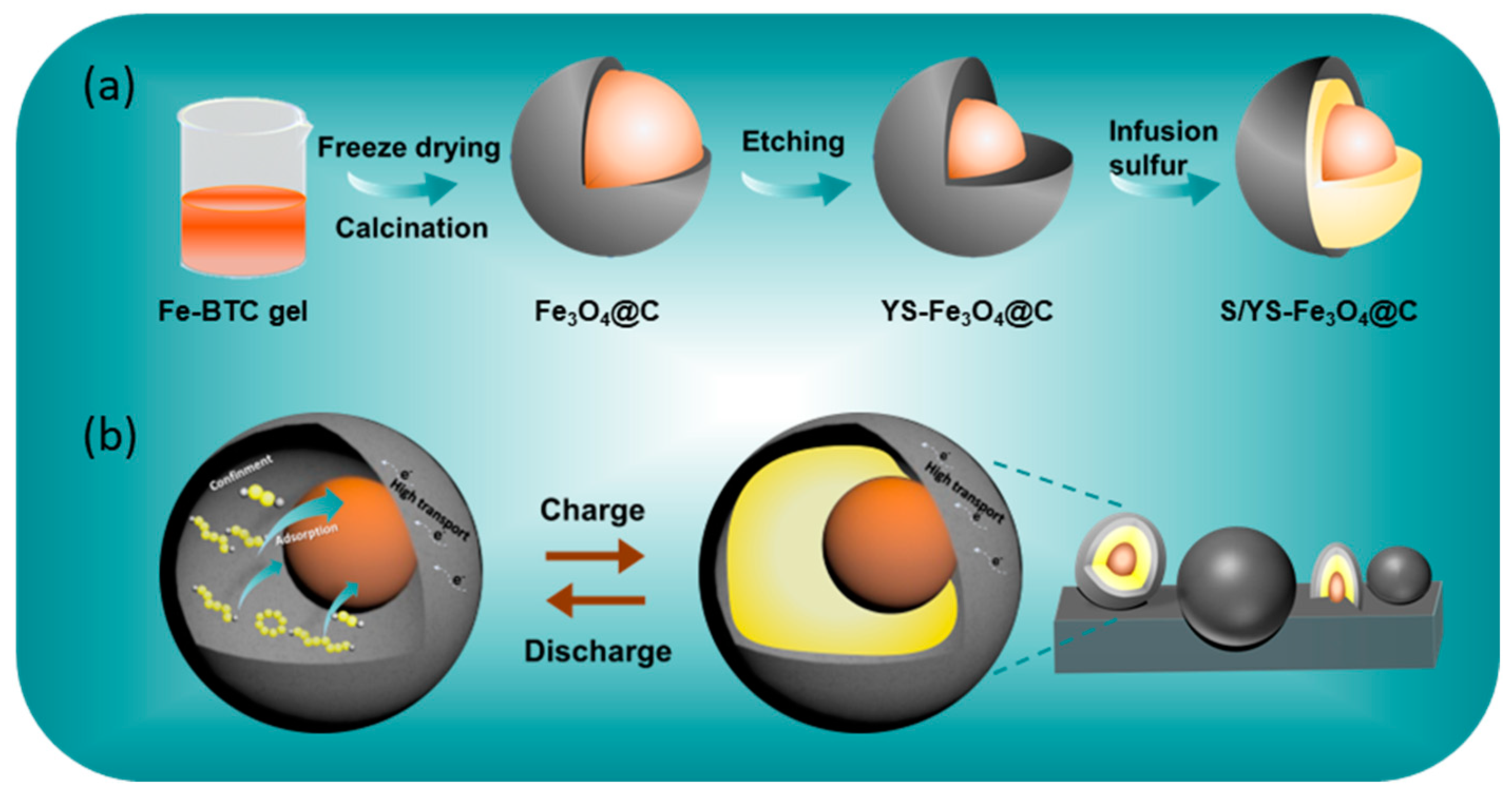
Figure 1. Schematic illustration of (a) the preparation of S/YS-Fe3O4@C composite and (b) the conversion process of sulfur in the yolk-shelled structure for S/YS-Fe3O4@C cells.
Batteries 09 00295 g001
Figure 2. (a) SEM, (b) TEM, and (c) HADDF-TEM image of Fe3O4@C. (d1,e1,f1) FFT patterns and (d2,e2,f2) enlarged TEM images of the selected areas of (c). EDS elemental mapping of Fe (g1), O (g2), and C (g3). (h) XRD profiles and (i) Raman spectra of Fe3O4@C.
Batteries 09 00295 g002
Figure 3. (a) TGA and (b) DTG curves of the Fe3O4@C and YS-Fe3O4@C in air. Morphology characterizations: SEM images of (c) YS-55Fe3O4@C, (d) YS-27Fe3O4@C, and (e) YS-13Fe3O4@C; TEM images of (f) YS-55Fe3O4@C, (g) YS-27Fe3O4@C, and (h) YS-13Fe3O4@C.
Batteries 09 00295 g003
Figure 4. (a) XRD patterns of S/Fe3O4@C. (b) TGA curves of S/Fe3O4@C and S/YS-Fe3O4@C in N2. EDS elemental mapping images of (c) S/Fe3O4@C and (d) YS-27Fe3O4@C.
Batteries 09 00295 g004
Figure 5. (a) The cycling stability performances of Li-S batteries with S/Fe3O4@C, S/YS-55Fe3O4@C, S/YS-27Fe3O4@C, and S/YS-13Fe3O4@C (1 C rate for 200 cycles); Charge/discharge profiles at (b) 0.1 C and (c) 1 C; (d) CV curves of S/YS-27Fe3O4@C and S/Fe3O4@C in the first cycle at 0.1 mV s−1; (e) Rate capability performances at various current densities; (f) Cycle performance at 0.1 C of S/YS-27Fe3O4@C under high sulfur loadings; (g) Electrical conductivity of YS-Fe3O4@C and Fe3O4@C was evaluated under different forces; Nyquist plots (h) before cycling and (i) after cycling.
Batteries 09 00295 g005
Figure 6. XPS spectrum of Fe 2p (a) before cycling and (b) after cycling. (c) In situ XRD contour plots of S/YS-27Fe3O4@C electrode in the first discharge/charge process within the voltage window of 1.7–2.8 V.
Batteries 09 00295 g006
Disclaimer/Publisher’s Note: The statements, opinions and data contained in all publications are solely those of the individual author(s) and contributor(s) and not of MDPI and/or the editor(s). MDPI and/or the editor(s) disclaim responsibility for any injury to people or property resulting from any ideas, methods, instructions or products referred to in the content.