Abstract
The NASICON-type (Sodium Super Ionic Conductor) Na3Zr2Si2PO12 solid electrolyte is one of the most promising electrolytes for solid-state sodium metal batteries. When preparing Na3Zr2Si2PO12 ceramic using a traditional high-temperature solid-state reaction, the high-densification temperature would result in the volatilization of certain elements and the consequent generation of impurity phase, worsening the functional and mechanical performance of the NASICON electrolyte. We rationally introduced the sintering additive B2O3 to the NASICON matrix and systemically investigated the influence of B2O3 on the crystal structure, microstructure, electrical performance, and electrochemical performance of the NASICON electrolytes. The results reveal that B2O3 can effectively reduce the densification sintering temperature and promote the performance of the Na3Zr2Si2PO12 electrolyte. The Na3Zr2Si2PO12-2%B2O3-1150 ℃ achieves the highest ionic conductivity of 4.7 × 10⁻⁴ S cm−1 (at 25 °C) with an activation energy of 0.33 eV. Furthermore, the grain boundary phase formed during the sintering process could improve the mechanical behavior of the grain boundary and inhibit the propagation of metallic sodium dendrite within the NASICON electrolyte. The assembled Na/Na3Zr2Si2PO12-2%B2O3/Na3V1.5Cr0.5(PO4)3 cell reveals the initial discharge capacity of 98.5 mAh g−1 with an initial Coulombic efficiency of 84.14% and shows a capacity retention of 70.3% at 30 mA g−1 over 200 cycles.
1. Introduction
At present, fossil energy is being consumed at an excessive rate; thus, there is an urgent need to expand research into other types of new energy sources. In the meantime, new types of energy storage systems are also required [,,,,]. Among these, electrochemical energy storage has attracted popular research interest owing to its high-energy conversion efficiency and ease of maintenance [,,]. Currently, the consumer market is dominated by commercial lithium-ion batteries, but the limited reserves of lithium resources hinder their further development and utilization. The sodium-ion battery is deemed one of the promising candidates for the lithium-ion battery system because of its wide availability and homogeneous distribution on Earth [,,]. However, sodium-ion batteries with organic liquid electrolytes have issues of easy leakage, flammability, and the growth of sodium dendrites. Solid-state batteries with solid-state electrolytes rather than traditional organic electrolytes can well address the above-mentioned issues [,,]. The solid-state electrolyte plays a crucial role in the performance of the solid-state battery. In general, solid-state electrolytes are required to have favorable room-temperature ionic conductivity, high stability in the air, and excellent mechanical properties [,].
The NASICON electrolyte with a stoichiometry of Na1+xZr2SixP3-xO12 (0 ≤ x ≤ 3) is obtained by partially replacing P with Si in NaZr2P3O12 [,]. The NASICON electrolyte has the highest room-temperature ionic conductivity of about 10−4 S cm−1 when x = 2 (Na3Zr2Si2PO12). Recently, various emerging methods of preparing Na3Zr2Si2PO12 ceramic electrolyte with high performance have appeared, such as spark plasma sintering (SPS), microwave-assisted sintering, hot pressing (HP), and the cold sintering process (CSP), but these preparation methods always need special equipment and are costly [,,,]. Usually, the high-temperature solid-state reaction is utilized to prepare Na3Zr2Si2PO12 ceramic. However, the high-sintering temperature would bring about the volatilization of sodium and phosphorus elements, producing impurity phase ZrO2 at the grain boundary [,,]. Moreover, abnormal grain growth is also accompanied by the deteriorated mechanical property of NASICON electrolytes. Therefore, low-cost and low-sintering temperatures are imperative for the large-scale synthesis of NASICON electrolytes. The sintering additive-assisted solid-state reaction is a well-known approach for ceramic sintering. At a certain temperature, the sintering additives would change into a liquid phase at the grain boundary. Furthermore, on account of the surface tension, the liquid phase would spontaneously fill the voids between the grains. Accordingly, this liquid phase plays an important role in facilitating mass migration during the sintering process and effectively lowers the densification sintering temperature. After sintering, the liquid phase would present as an amorphous phase lying at the grain boundary, resulting in dense microstructure and enhanced mechanical behavior.
In this work, Na3Zr2Si2PO12-xB2O3 ceramic electrolytes were synthesized through the solid-state reaction. The B2O3 would change into a liquid phase during the high-temperature sintering process, consequently promoting the densification sintering process. The charge transfer capability of Na3Zr2Si2PO12-xB2O3 is improved owing to the as-obtained dense microstructure and reduced grain boundary resistance. In the meantime, the interface compatibility between the ceramic electrolyte and metallic Na anode has also been greatly boosted. As a result, the assembled solid-state full battery operates well at room temperature and reveals excellent electrochemical performance, highlighting the effectiveness of grain boundary engineering in a solid-state electrolyte toward a rechargeable solid-state metal battery.
2. Experimental Section
2.1. Synthesis of Na3Zr2Si2PO12-B2O3 Ceramics
Na3Zr2Si2PO12-xB2O3 (abbreviated as NZSP-xB2O3, x = 0, 1, 2, and 4 wt.%) ceramics were synthesized through the conventional solid-state reaction. Na2CO3 (99.5%), ZrO2 (99.99%), SiO2 (99.5%), and NH4H2PO4 (99.0%) were utilized as raw materials without further treatment. In order to compensate for the volatilization of sodium element during the sintering process, an excessive amount of Na2CO3 (10 wt.%) was added. Anhydrous ethanol was used as the milling medium when the weighted raw materials in accordance with as-designed compositions were thoroughly ball-milled. Thereafter, the mixtures were dried in an electric oven at 60 °C for 12 h. The dried powder was pre-calcinated in a muffle at 1000 °C/10 h (with a heating rate of 5 °C min−1). Afterwards, the as-obtained products with different amounts of B2O3 (0, 1, 2, and 4 wt.%) were ball-milled again (same conditions as previous) and pressed into pellets with a diameter of 10 mm under 10 MPa and then sintered at different temperatures (1050, 1100, 1150, and 1250 °C) for 10 h. After sintering, the as-obtained ceramic pellets had a thickness of about 1 mm and a diameter of 8–9 mm. The as-sintered ceramics were carefully polished with sand paper prior to use.
2.2. Microstructure and Performance Characterization
The phase structure of the samples was identified with an X-ray diffractometer with Cu Kα radiation (λ = 1.5418 Å, Bruker D8 Advance). A field emission scanning electron microscope (Hitachi Regulus8230) equipped with an energy dispersive spectrometer was adopted for microstructural and composition analysis. The ionic conductivity was assessed using AC impedance analysis (Chenhua 660E). The measured frequency range was 1 MHz~0.1 Hz. The equivalent circuit was fitted in the Nyquist plot using the Z-view software. The total ionic conductivity (σt) can be calculated using σ = , wherein S1 is the area of the ceramic pellet, R is the total resistance of the ceramic pellet, and L is the thickness of the ceramic pellet. The interfacial area specific resistance (ASR) is computed using ASR = Rinterface × S2, wherein Rinterface is the interfacial resistance between the metallic sodium anode and the solid electrolyte, and S2 is the contact area of the sodium metal anode with the solid electrolyte. The galvanostatic charge/discharge measurement was conducted on a battery testing system (Land multi-channel battery test instrument, Wuhan, China).
2.3. Synthesis of the Composite Cathode
The cathode active material Na3V1.5Cr0.5(PO4)3 was prepared according to our previous research [,]. Na3V1.5Cr0.5(PO4)3 (the carbon content of about 3 wt.%), plastic-crystal electrolyte, polyvinylidene fluoride (PVDF), and carbon black were mixed with a weight ratio of 60:25:10:5 to create the composite cathode. Herein, the plastic-crystal electrolyte was prepared by heating a 20:1 molar mixture of succinonitrile and NaClO4 to achieve a clear solution at 65 °C, then allowing it naturally cool to 25 °C. This composite cathode was dispersed in N-methyl-2-pyrrolidone and stirred for 12 h. The as-achieved slurry was carefully coated onto aluminum foil and dried at 40 °C for another 12 h under vacuum. The loading mass of active material was about 2–3 mg cm−2.
2.4. Assemble and Disassemble Cells
To test the electrochemical performance of the cells, CR2032 coin cells with ceramics as the electrolyte and sodium metal (with an area of about 0.3 cm2) as the anode were assembled. The ceramic electrolyte was sandwiched between sodium foil and the composite cathode. Before assembling the solid-state sodium metal battery, the as-sintered ceramics were carefully polished with sand paper. The Na metal was pressed onto one side of the ceramic electrolyte by hand; the as-synthesized cathode was placed onto the other side. Next, the CR2032 cell was sealed at 10 MPa.
The packaged cell case was opened and the sodium metal on the solid electrolyte surface was removed. To observe the combination of metallic sodium anode with the ceramic electrolyte, we broke the ceramic electrolyte along its diameter to obtain a complete cross-section. The whole process of assembling and disassembling was completed in a glove box filled with Ar and the transfer for XPS analysis was also finished in a homemade container with the protection of Ar.
3. Results and Discussion
The crystal structure of the as-obtained ceramics was identified using XRD analysis. Figure 1a shows the XRD patterns of Na3Zr2Si2PO12-xB2O3 sintered at 1150 °C (abbreviated as NZSP-xB2O3—1150 °C). All diffraction peaks show a good match to the monoclinic phase Na3Zr2Si2PO12 (PDF#: 84-1200), suggesting that the introduction of B2O3 could not vary the main phase structure of the NASICON matrix. In addition, no obvious diffraction peaks associated with B2O3 could be identified, and it is possible that B2O3 exists as an amorphous phase at the grain boundary after sintering. In addition, the ZrO2 phase can be clearly observed, which is attributed to the sodium and phosphorus elements volatilizing during the high-temperature sintering process [,,].
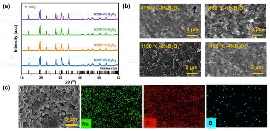
Figure 1.
(a) XRD patterns of NZSP-xB2O3—1150 °C. (b) Sectional SEM images. (c) EDS mapping results for the surface of NZSP-2%B2O3—1150 °C.
The sectional SEM images of NZSP-xB2O3—1150 °C are presented in Figure 1b and the SEM analysis results of the other samples are summarized in Figure S1. The result indicates that bare NZSP has clear grain boundaries together with a certain number of pores. In addition, an intergranular fracture morphology and an abnormal grain growth are observed for the bare NZSP, implying a weak grain–grain bonding strength. In contrast, the NZSP-xB2O3 samples present bigger grain sizes, fewer pores, and blurred grain boundaries covered by the amorphous phase, demonstrating a much denser microstructure. The reason for this is that the liquid phase would form at the grain boundaries when the temperature reaches the melting point of B2O3 (450 °C) and fill the pores between these grains, resulting in a closer grain contact. With the increase in B2O3 content, the fracture behavior of ceramics changes from an intergranular to a transcrystalline fracture, indicating that the grain bonding strength was observably enhanced []. Moreover, by observing the microstructure of the ceramic electrolytes obtained at different sintering temperatures, it can be concluded that the B2O3-modified NZSP ceramics can obtain a denser microstructure at lower temperatures, suggesting that the liquid phase formed during the sintering process can effectively facilitate the migration of mass and reduce the densification temperature of the NASICON matrix. The energy dispersive spectroscopy (EDS) results of the surface for NZSP-2%B2O3—1150 °C (Figure 1c) and the results with an enlarged scale (Figures S2 and S3) show the uniform distribution of elements over the sample. Furthermore, element B is uniformly dispersed at the grain boundary. The shrinkage variation of NZSP-xB2O3 is exhibited in Figure S4. The B2O3-modified NZSP sintered at low temperatures also can shrink considerably compared with bare NZSP. Again, this reconfirms that the liquid phase can promote the densification sintering, which is consistent with the SEM analysis results.
Figure 2 exhibits the Rietveld refinement results of the samples and Table S1 displays detailed information about the crystal structure. Generally, all of these samples possess a typical NASICON structure with a space group of C2/c, implying that the B2O3 as a sintering additive does not change the structure of the NASICON matrix. As listed in Table S1, the lattice parameters and cell volume changed after B2O3, suggesting that the composition of phases changed after B2O3 addition. This can be explained by the present matrix phase possibly being a deviation from Na3Zr2Si2PO12, that is, for example, Na-rich NZSP (Na3+xZr2−ySi2PO12). Then, additional Na may react with B2O3 to form a Na-B-O compound that may act as a good sintering additive located at the grain boundary, which is consistent with the results of the SEM-EDS.
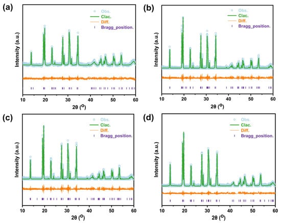
Figure 2.
Rietveld refinement plots of (a) NZSP—1250 °C, (b) NZSP-1%B2O3—1150 °C, (c) NZSP-2%B2O3—1150 °C, and (d) NZSP-4%B2O3—1150 °C.
Ionic conductivity is an important parameter to assess the capability of ion transport in the electrolyte. Electrochemical impedance spectra (EIS) analysis was performed with these ceramic samples. The EIS plots are collected in Figure 3a, Figures S5 and S6. Typically, the impedance spectra of NZSP-xB2O3 consist of a sloping line in a low-frequency region and a semicircle in a high-frequency range [,]. Furthermore, the room temperature ionic conductivity was calculated according to the resistance obtained from the impedance spectra and corresponding results are collected in Figure 3b. The ionic conductivity of NZSP-xB2O3—1050 °C and NZSP-xB2O3—1100 °C increases monotonously with increasing B2O3 content, but NZSP-xB2O3—1150 °C increases first and then decreases. NZSP-4%B2O3—1050 °C, NZSP-4%B2O3—1100 °C, and NZSP-2%B2O3—1150 °C achieve ionic conductivity of 4.4 × 10⁻⁴, 4.6 × 10⁻⁴, and 4.7 × 10⁻⁴ S cm−1. In other words, NZSP-xB2O3 sintered at lower sintering temperatures can achieve the same or even better room temperature ionic conductivity than bare NZSP sintered at 1250 °C (3.4 × 10⁻⁴ S cm−1). This can be ascribed to the dense microstructure and the increased average grain size [,,,]. However, when too much content of B2O3 is added, the ionic conductivity decreases. Figure 3c,d, Figures S7 and S8 show temperature-dependent Nyquist plots and Arrhenius plots of conductivities for these ceramic electrolytes. Furthermore, the activation energy (Ea) was computed and the Ea of NZSP-4%B2O3—1050 °C, NZSP-4%B2O3—1100 °C, NZSP-2%B2O3—1150 °C, and NZSP-1250 °C is 0.37, 0.37, 0.33, and 0.36 eV, respectively.
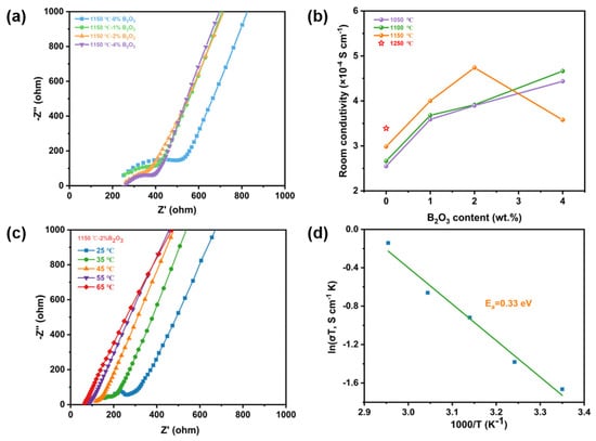
Figure 3.
(a) Nyquist plots of the impendence spectroscopy of NZSP-xB2O3—1150 °C. (b) The room temperature ionic conductivity of NZSP-xB2O3 obtained at different sintering temperatures. (c) The temperature-dependent Nyquist plots and (d) Arrhenius temperature-dependent total ionic conductivity plot of NZSP-2%B2O3—1150 °C.
Symmetrical sodium metal cells were assembled by using NZSP—1250 °C and NZSP-2%B2O3—1150 °C as the solid electrolytes to investigate the interfacial electrochemical behavior. Figure 4a shows the EIS plots of as-assembled symmetric batteries and the inset is the interfacial area specific resistance (ASR). Figure S9 shows the result of the fitted circuit simulation and the total impedance consists of electrolyte impedance and interface impedance. The impedance of the Na/NZSP-2%B2O3/Na symmetric battery is smaller than that of the Na/NZSP/Na symmetric battery. In addition, the symmetric battery with bare NZSP electrolyte has an ASR of 148 ohm cm2. Moreover, Na/NZSP-2%B2O3/Na presents an ASR of 67 ohm cm2, indicating that the engineered grain boundary can observably promote Na+ migration at the interface and improve the interfacial compatibility of metallic sodium and solid electrolyte. The total impedance of Na/NZSP-2%B2O3/Na symmetrical battery gets significantly reduced with increasing the temperature (Figure 4b). According to the corresponding Arrhenius plot (Figure 4c), the activation energy of sodium ion transfer at the Na/NZSP-2%B2O3 interface is about 0.33 eV, such a low value indicates that ion migration at the interfaces is dramatically facilitated []. Galvanostatic charge/discharge measurements were utilized to assess the cycling stability of as-assembled cells. As shown (Figure 4d), at room temperature the Na/NZSP-2%B2O3/Na battery presents a stable cycling performance at 0.05 mA cm−2 up to 1000 h with no significant variation in the polarization response, indicating the effective inhibition of metallic sodium dendrite growth. Moreover, the cycling performance of the symmetrical cell under variable current densities of 0.1–0.3 mA cm−2 at 60 °C was also assessed (Figure 4e,f). As observed, the polarization voltage hysteresis linearly increases with increasing the current density. The favorable cycling stability and rate performance are attributed to improved interfacial compatibility and effective inhibition of sodium dendrite growth.
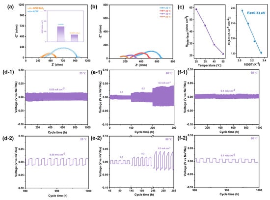
Figure 4.
(a) Room temperature EIS profiles of symmetric sodium metal batteries based on NZSP—1250 °C and NZSP-2%B2O3—1150 °C ceramic electrolytes. The inset is the comparison of the ASR of the interface between metallic sodium anode and solid electrolyte. (b) Temperature-dependence EIS profiles of symmetrical sodium metal batteries with NZSP-2%B2O3—1150 °C ceramic electrolyte. (c) The fitted overall areal specific resistance of the Na/NZSP-2%B2O3/Na cell against the temperature and the corresponding Arrhenius plot. (d-1) Voltage profiles of Na/NZSP-2%B2O3/Na cell at 0.05 mA cm−2 and 25 °C. (e-1,f-1) Voltage profiles of Na/NZSP-2%B2O3/Na cell at 0.1–0.3 mA cm−2 and 60 °C. (d-2,e-2,f-2) are corresponding locally enlarged images.
We dissembled the cycled symmetrical cell to gain more information about the interphase between the metallic sodium anode and NZSP-2%B2O3—1150 °C electrolyte. Figure 5a shows XPS analysis results of the section and surface of the ceramic electrolytes after electrochemical cycling. Obviously, the integral area and relative intensity of the Na 1s spectrum become larger owing to the increased surface roughness and coverage of interfacial products. In the meantime, the peak of Si 2p shifts toward the lower-binding energy indicating that the reduction in Si4+ would occur as the sodium metal contacts with the ceramic electrolyte, and the Zr 3d, P 2p, and B 1s are virtually unaffected. The overlay SEM-EDS mapping results of the cross-section of cycled symmetrical cells are provided in Figure 5b. After cycling, the ceramic electrolyte still has a dense microstructure, illustrating favorable mechanical properties; sodium metal is uniformly deposited onto the ceramic electrolyte surface, and no visible “dead sodium” can be observed. Furthermore, the sodium metal and ceramic electrolyte are tightly combined together and there is no appreciable gap between them, suggesting a high integrity of the interface. It should be noted that the evident demarcations within the region of Na metal are induced during the sample preparation process.

Figure 5.
(a) XPS spectra of the surface and section of cycled NZSP-2%B2O3—1150 °C ceramic electrolyte. (b) Cross−sectional SEM image and EDS mapping results of NZSP-2%B2O3—1150 °C/Na interface disassembled from cycled symmetric sodium metal cell. (c) The demonstration of interface contact between the ceramic electrolyte and the Na metal anode; the left is for Na/NZSP—1250 °C and the right is for Na/NZSP-2%B2O3—1150 °C.
The nucleation and growth of metal dendrites seriously affect the performance of solid-state metal batteries. In addition, metal dendrites are mainly formed at the interface between the solid electrode and the electrolyte, and the grain boundary of the solid-state electrolyte [,]. Usually, the grain boundary in polycrystalline ceramic electrolytes has low-ionic conductivity, poor mechanical strength, and high-electronic conductivity compared to the grain bulk [,]. On the one hand, the high-electronic conductivity of the grain boundary would drive the reduction in Na+, leading to the formation and growth of sodium dendrite at the grain boundary. Furthermore, the voids between the grains would provide an additional barrier to the Na+ transport, resulting in an increase in the grain boundary resistance for ionic transportation []. With the addition of B2O3 to the NASICON matrix, the amorphous phase formed after the sintering process can reduce the electronic conductivity of the NASICON grain boundary, hindering the formation of metallic sodium dendrite. In addition, the bonding strength of the grain boundaries is also increased and the penetration path of the sodium dendrites is blocked.
The nucleation and growth of dendrites at the interface are mainly ascribed to the inhomogeneous distribution of Na+ flux at the interface, and the loose microstructure of ceramic electrolyte would further degrade this circumstance [,]. However, using the B2O3-modified NASICON electrolyte can enhance the interface contact of the metallic sodium anode and ceramic electrolyte, alleviating the edging effect and homogenizing the distribution of Na+ (Figure 5c).
The solid-state sodium battery is assembled with Na3V1.5Cr0.5(PO4)3 as the cathode active material and NZSP-2%B2O3—1150 °C as the ceramic electrolyte. Figure 6a shows the schematic diagram of the solid-state sodium battery and the room temperature EIS plot fitted according to the equivalent circuit displayed in the illustration. Figure 6b shows the initial charge/discharge profiles of the as-assembled solid-state battery at 30 mA g−1 and the initial discharge capacity of 98.5 mAh g−1 achieves a Coulombic efficiency of 84.14%. The long-term cycling performance of the solid-state battery with NZSP—1250 °C as the ceramic electrolyte is demonstrated in Figure 6c. The capacity of the solid-state battery decays rapidly with a capacity retention of 48% after 200 cycles. However, the solid-state battery with NZSP-2%B2O3—1150 °C electrolyte has a capacity retention of 70.3% after 200 cycles at 30 mA g−1 (Figure 6c), which is mainly ascribed to the enhanced ionic conductivity of the ceramic electrolyte and the improved interfacial compatibility of metallic Na and NASICON electrolytes. As shown in Figure 6d, the solid-state sodium metal battery can offer reversible capacities of 106.8, 78.4, and 70.6 mAh g−1 at 30, 100, and 200 mAh g−1, respectively. The specific capacity can be fully restored to its initial state following a complete rate trial, highlighting the advantage of an all-solid-state sodium metal battery based on a stable Na/NZSP-2%B2O3—1150 °C interface.
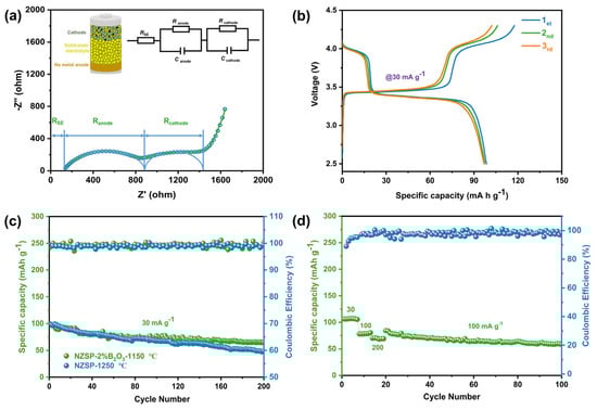
Figure 6.
Electrochemical performance of the solid-state sodium metal batteries based on NZSP-2%B2O3—1150 °C ceramic electrolytes. (a) The impedance profile of solid-state sodium metal battery. (b) The initial charge/discharge curves of the solid-state sodium metal batteries at a current density of 30 mA g−1. (c) Cycling performance of the solid-state sodium metal batteries based on NZSP—1250 °C and NZSP-2%B2O3—1150 °C ceramic electrolytes. (d) Rate performance of the solid-state sodium metal batteries based on NZSP-2%B2O3—1150 °C ceramic electrolytes.
4. Conclusions
In summary, NZSP-xB2O3 ceramics were prepared using a sintering additive-assisted solid-state reaction. With a low-melting point of 450 °C, B2O3 would change into a liquid phase at a certain temperature during the sintering process and fill the voids between the grains, thus, accelerating the process of densification sintering and then achieving a dense microstructure. After sintering, the liquid phase exists at the grain boundary as an amorphous phase, reducing the electronic conductivity of the grain boundary and impeding the formation of metallic sodium dendrites. Furthermore, the engineered grain boundary is also beneficial to promote the interface contact between the ceramic electrolyte and the metallic sodium anode, effectively lowering the ASR from 148 to 67 ohm cm2. Eventually, the B2O3-modified NASICON-type electrolyte-based all-solid-state sodium batteries were constructed and the desirable electrochemical performance was realized.
Supplementary Materials
The following supporting information can be downloaded at: https://www.mdpi.com/article/10.3390/batteries9050252/s1, Figure S1. Sectional SEM images of the NZSP-xB2O3—1050 °C and NZSP-xB2O3—1100 °C ceramics. Figure S2. EDS mapping results with an enlarged scale for NZSP-2%B2O3—1150 °C ceramic. Figure S3. Energy spectrum element analysis of grain boundaries for NZSP-2%B2O3—1150 °C ceramic. Figure S4. Shrinkage variation of the NZSP-xB2O3 ceramics pellets sintered at different temperatures. Figure S5. Nyquist plots of the room temperature EIS of (a) NZSP-xB2O3—1050 °C and (b) NZSP-xB2O3—1100 °C ceramic pellets. Figure S6. Nyquist plots of NZSP—1250 °C. Figure S7. The temperature-dependent Nyquist plots of (a) NZSP-4%B2O3—1050 °C, (c) NZSP-4%B2O3—1100 °C, and (e) NZSP—1250 °C. The Arrhenius temperature-dependent total conductivity plots of (b) NZSP-4%B2O3—1050 °C, (d) NZSP-4%B2O3—1100 °C, and (f) NZSP—1250 °C. Figure S8. Nyquist plot of NZSP-2%B2O3—1150 °C at room temperature, simulation results based on the equivalent circuit, and illustration of analysis of Rb and Rgb. Figure S9. Room temperature Nyquist plots of symmetric sodium metal batteries based on NZSP—1250 °C and NZSP-2%B2O3—1150 °C ceramic electrolytes. The insets are the equivalent circuit and illustration of analysis of RSE and Rt. Table S1. Cell Parameters and volume of NZSP-xB2O3.
Author Contributions
Conceptualization, Y.Z.; Formal analysis, Y.L. and Z.S.; Funding acquisition, Y.Z.; Investigation, H.J. and Y.Z.; Methodology, Y.L. and Z.S.; Project administration, H.J. and Y.Z.; Software, Z.S.; Validation, Y.L.; Writing—original draft, Y.L.; Writing—review & editing, Y.Z. All authors have read and agreed to the published version of the manuscript.
Funding
Y.Z. acknowledges funding support from the National Natural Science Foundation of China (No. 52072033), the State Key Laboratory of New Ceramic and Fine Processing Tsinghua University (No. 202211), the Open Research Fund of Songshan Lake Materials Laboratory (No. 2022SLABFN24), and the Graduate Interdisciplinary Innovation Project of Yangtze Delta Region Academy of Beijing Institute of Technology (Jiaxing), No. GIIP2022-014.
Data Availability Statement
The data presented in this study are available upon request from the corresponding author.
Conflicts of Interest
The authors declare no conflict of interest.
References
- Dehghani-Sanij, A.R.; Tharumalingam, E.; Dusseault, M.B.; Fraser, R. Study of energy storage systems and environmental challenges of batteries. Renew. Sust. Energ. Rev. 2019, 104, 192–208. [Google Scholar] [CrossRef]
- Olabi, A.G. Renewable energy and energy storage systems. Energy 2017, 136, 1–6. [Google Scholar] [CrossRef]
- Ould Amrouche, S.; Rekioua, D.; Rekioua, T.; Bacha, S. Overview of energy storage in renewable energy systems. Int. J. Hydrog. Energy 2016, 41, 20914–20927. [Google Scholar] [CrossRef]
- Guney, M.S.; Tepe, Y. Classification and assessment of energy storage systems. Renew. Sust. Energ. Rev. 2017, 75, 1187–1197. [Google Scholar] [CrossRef]
- Olabi, A.G.; Onumaegbu, C.; Wilberforce, T.; Ramadan, M.; Abdelkareem, M.A.; Al-Alami, A.H. Critical review of energy storage systems. Energy 2021, 214, 118987. [Google Scholar] [CrossRef]
- Chen, K.F.; Xue, D.F. Materials chemistry toward electrochemical energy storage. J. Mater. Chem. A 2016, 4, 7522–7537. [Google Scholar] [CrossRef]
- Ragupathy, P.; Bhat, S.D.; Kalaiselvi, N. Electrochemical energy storage and conversion: An overview. WIREs Energy Environ. 2022, 12, e464. [Google Scholar] [CrossRef]
- Yang, Y.Q.; Bremner, S.; Menictas, C.; Kay, M. Battery energy storage system size determination in renewable energy systems: A review. Renew. Sust. Energ. Rev. 2018, 91, 109–125. [Google Scholar] [CrossRef]
- Vaalma, C.; Buchholz, D.; Weil, M.; Passerini, S. A cost and resource analysis of sodium-ion batteries. Nat. Rev. Mater. 2018, 3, 18013. [Google Scholar] [CrossRef]
- Hwang, J.-Y.; Myung, S.-T.; Sun, Y.-K. Sodium-ion batteries: Present and future. Chem. Soc. Rev. 2017, 46, 3529–3614. [Google Scholar] [CrossRef]
- Hou, D.W.; Xia, D.W.; Gabriel, E.; Russell, J.A.; Graff, K.; Ren, Y.; Sun, C.-J.; Lin, F.; Liu, Y.Z.; Xiong, H. Spatial and temporal analysis of sodium-ion batteries. ACS Energy Lett. 2021, 6, 4023–4054. [Google Scholar] [CrossRef] [PubMed]
- Wang, L.G.; Li, J.; Lu, G.L.; Li, W.Y.; Tao, Q.Q.; Shi, C.H.; Huile, J.; Chen, G.; Wang, S. Fundamentals of electrolytes for solid-state batteries: Challenges and perspectives. Front. Mater. 2020, 7, 111. [Google Scholar] [CrossRef]
- Yu, X.Q.; Chen, R.S.; Gan, L.Y.; Li, H.; Chen, L.Q. Battery safety: From lithium-ion to solid-state batteries. Engineering 2022, 21, 9–14. [Google Scholar] [CrossRef]
- Zhao, Q.; Stalin, S.; Zhao, C.-Z.; Archer, L.A. Designing solid-state electrolytes for safe, energy-dense batteries. Nat. Rev. Mater. 2020, 5, 229–252. [Google Scholar] [CrossRef]
- Murgia, F.; Brighi, M.; Piveteau, L.; Avalos, C.E.; Gulino, V.; Nierstenhöfer, M.C.; Ngene, P.; Jongh, P.; CČerny, R. Enhanced room-temperature ionic conductivity of NaCB11H12 via high-energy mechanical milling. ACS Appl. Mater Inter. 2021, 13, 61346–61356. [Google Scholar] [CrossRef]
- Till, P.; Agne, M.T.; Kraft, M.A.; Courty, M.; Famprikis, T.; Ghidiu, M.; Krauskopf, T.; Masquelier, C.; Zeier, W.G. Two-dimensional substitution series Na3P1–xSbxS4–ySey: Beyond static description of structural bottlenecks for Na+ Transport. Chem. Mater. 2022, 34, 2410–2421. [Google Scholar] [CrossRef]
- Liu, L.M.; Liang, D.S.; Zhou, X.L.; Liu, Y.J.; Su, J.W.; Xu, Y.; Peng, J.S. Enhancing Na-ion conducting capacity of NASICON ceramic electrolyte Na3.4Zr2Si2.4P0.6O12 by NaF sintering aid. J. Mater. Sci. 2022, 57, 11774–11782. [Google Scholar] [CrossRef]
- Oh, J.A.S.; He, L.C.; Plewa, A.; Morita, M.; Zhao, Y.; Sakamoto, T.; Song, X.; Zhai, W.; Zeng, K.Y.; Lu, L. Composite NASICON (Na3Zr2Si2PO12) solid-state electrolyte with enhanced Na+ ionic conductivity: Effect of liquid phase sintering. Acs App. Mater. Interfaces 2019, 11, 40125–40133. [Google Scholar] [CrossRef]
- Grady, Z.; Fan, Z.M.; Ndayishimiye, A.; Randall, C.A. Design and sintering of all-solid-state composite cathodes with tunable mixed conduction properties via the cold sintering process. ACS Appl. Mater. Interfaces 2021, 13, 48071–48087. [Google Scholar] [CrossRef]
- Leng, H.Y.; Huang, J.J.; Nie, J.Y.; Luo, J. Cold sintering and ionic conductivities of Na3.256Mg0.128Zr1.872Si2PO12 solid electrolytes. J. Power Sources 2018, 391, 170–179. [Google Scholar] [CrossRef]
- Li, Y.; Li, M.; Sun, Z.; Ni, Q.; Jin, H.B.; Zhao, Y.J. Recent advance on NASICON electrolyte in solid-state sodium metal batteries. Energy Storage Mater. 2023, 56, 582–599. [Google Scholar] [CrossRef]
- Zhang, X.; Wang, J.X.; Wen, J.W.; Wang, Y.; Li, N.; Wang, J.; Fan, L.J. Improvement of ionic conductivity and densification of Na3Zr2Si2PO12 solid electrolyte rapidly prepared by microwave sintering. Ceram. Int. 2022, 48, 18999–19005. [Google Scholar] [CrossRef]
- Fuentes, R.O.; Figueiredo, F.M.; Marques, F.M.B.; Franco, J.I. Processing and electrical properties of NASICON prepared from yttria-doped zirconia precursors. J. Eur. Ceram. Soc. 2001, 21, 737–743. [Google Scholar] [CrossRef]
- Krok, F. Influence of sintering conditions on chemical composition of NASICON. Solid State Ion. 1987, 24, 21–28. [Google Scholar] [CrossRef]
- Li, Y.; Sun, Z.; Sun, C.; Jin, H.B.; Zhao, Y.J. Exploring the origin of ZrO2 phase in Na3Zr2Si2PO12 ceramic electrolyte. Ceram. Int. 2023, 49, 3094–3098. [Google Scholar] [CrossRef]
- Zhao, Y.J.; Gao, X.W.; Gao, H.C.; Jin, H.B.; Goodenough, J.B. Three electron reversible redox reaction in sodium vanadium chromium phosphate as a high-energy-density cathode for sodium-ion batteries. Adv. Funct. Mater. 2020, 30, 1908680. [Google Scholar] [CrossRef]
- Sun, C.; Zhao, Y.J.; Ni, Q.; Sun, Z.; Yuan, X.Y.; Li, J.B.; Jin, H.B. Reversible multielectron redox in NASICON cathode with high energy density for low-temperature sodium-ion batteries. Energy Storage Mater. 2022, 49, 291–298. [Google Scholar] [CrossRef]
- Zheng, C.J.; Lu, Y.; Su, J.M.; Song, Z.; Xiu, T.P.; Jin, J.; Badding, M.E.; Wen, Z.Y. Grain boundary engineering enabled high-performance garnet-type electrolyte for lithium dendrite free lithium metal batteries. Small Methods 2022, 6, e2200667. [Google Scholar] [CrossRef]
- Thokchom, J.S.; Kumar, B. The effects of crystallization parameters on the ionic conductivity of a lithium aluminum germanium phosphate glass-ceramic. J. Power Sources 2010, 195, 2870–2876. [Google Scholar] [CrossRef]
- Zhao, X.C.; Luo, Y.S.; Zhao, X.J. Effect of TeO2 sintering aid on the microstructure and electrical properties of Li1.3Al0.3Ti1.7(PO4)3 solid electrolyte. J. Alloy. Compd. 2022, 927, 167019. [Google Scholar] [CrossRef]
- He, S.N.; Xu, Y.L.; Chen, Y.J.; Ma, X.N. Enhanced ionic conductivity of an F−-assisted Na3Zr2Si2PO12 solid electrolyte for solid-state sodium batteries. J. Mater. Chem. A 2020, 8, 12594–12602. [Google Scholar] [CrossRef]
- Naqash, S.; Ma, Q.; Tietz, F.; Guillon, O. Na3Zr2(SiO4)2(PO4) prepared by a solution-assisted solid state reaction. Solid State Ion. 2017, 302, 83–91. [Google Scholar] [CrossRef]
- Park, H.; Jung, K.; Nezafati, M.; Kim, C.-S.; Kang, B. Sodium ion diffusion in Nasicon (Na3Zr2Si2PO12) solid electrolytes: Effects of excess sodium. ACS Appl. Mater. Interfaces 2016, 8, 27814–27824. [Google Scholar] [CrossRef] [PubMed]
- Shao, Y.J.; Zhong, G.M.; Lu, Y.X.; Liu, L.L.; Zhao, C.L.; Zhang, Q.Q.; Hu, Y.-S.; Yang, Y.; Chen, L.Q. A novel NASICON-based glass-ceramic composite electrolyte with enhanced Na-ion conductivity. Energy Storage Mater. 2019, 23, 514–521. [Google Scholar] [CrossRef]
- Zhao, Y.J.; Wang, C.Z.; Dai, Y.J.; Jin, H.B. Homogeneous Na+ transfer dynamic at Na/Na3Zr2Si2PO12 interface for all solid-state sodium metal batteries. Nano Energy 2021, 88, 106293. [Google Scholar] [CrossRef]
- Aslam, M.K.; Niu, Y.B.; Hussain, T.; Tabassum, H. How to avoid dendrite formation in metal batteries: Innovative strategies for dendrite suppression. Nano Energy 2021, 86, 106142. [Google Scholar] [CrossRef]
- Gao, Z.H.; Yang, J.Y.; Li, G.C.; Ferber, T.; Feng, J.R.; Li, Y.Y.; Fu, H.Y.; Jaegermann, W.; Monroe, C.W.; Huang, Y.H. TiO2 as second phase in Na3Zr2Si2PO12 to suppress dendrite growth in sodium metal solid-state batteries. Adv. Energy Mater. 2022, 12, 2103607. [Google Scholar] [CrossRef]
- Wang, X.X.; Chen, J.J.; Mao, Z.Y.; Wang, D.J. Effective resistance to dendrite growth of NASICON solid electrolyte with lower electronic conductivity. Chem. Eng. J. 2022, 427, 130899. [Google Scholar] [CrossRef]
- Oh, J.A.S.; He, L.C.; Chua, B.; Zeng, K.Y.; Lu, L. Inorganic sodium solid-state electrolyte and interface with sodium metal for room-temperature metal solid-state batteries. Energy Storage Mater. 2021, 34, 28–44. [Google Scholar] [CrossRef]
- Ruan, Y.L.; Guo, F.; Liu, J.J.; Song, S.D.; Jiang, N.Y.; Cheng, B.W. Optimization of Na3Zr2Si2PO12 ceramic electrolyte and interface for high performance solid-state sodium battery. Ceram. Inter. 2019, 45, 1770–1776. [Google Scholar] [CrossRef]
Disclaimer/Publisher’s Note: The statements, opinions and data contained in all publications are solely those of the individual author(s) and contributor(s) and not of MDPI and/or the editor(s). MDPI and/or the editor(s) disclaim responsibility for any injury to people or property resulting from any ideas, methods, instructions or products referred to in the content. |
© 2023 by the authors. Licensee MDPI, Basel, Switzerland. This article is an open access article distributed under the terms and conditions of the Creative Commons Attribution (CC BY) license (https://creativecommons.org/licenses/by/4.0/).