Article

Evaluation of Glyoxal-Based Electrolytes for Lithium-Sulfur Batteries

1
Department of Chemical Surface Technology, Fraunhofer Institute for Material and Beam Technology (IWS), Winterbergstraße 28, 01277 Dresden, Germany
2
Department of Inorganic Chemistry I, Technische Universität Dresden, Bergstraße 66, 01069 Dresden, Germany
3
Institute for Technical Chemistry and Environmental Chemistry, Friedrich Schiller University Jena, Philosophenweg 7a, 07743 Jena, Germany
4
Center for Energy and Environmental Chemistry Jena (CEEC Jena), Friedrich Schiller University Jena, Philosophenweg 7a, 07743 Jena, Germany
*
Author to whom correspondence should be addressed.
Batteries 2023, 9(4), 210; https://doi.org/10.3390/batteries9040210
Submission received: 23 January 2023 / Revised: 24 March 2023 / Accepted: 27 March 2023 / Published: 31 March 2023
(This article belongs to the Special Issue Lithium-Sulfur Batteries: Research Progress of Key Materials)

Abstract

:
Lithium-sulfur batteries (LSBs) are among the most promising next generation battery technologies. First prototype cells show higher specific energies than conventional Li-ion batteries (LIBs) and the active material is cost-effective and ubiquitously abundant. However, Li-S batteries still suffer from several limitations, mainly the cycle life, inflation of cells, and also the lack of a component production value chain. As this battery system is based on a complex conversion mechanism, the electrolyte plays a key role, not only for specific energy, but also for rate capability, cycle stability and costs. Herein, we report on electrolytes based on glyoxylic-acetal based solvents, Tetraethoxyglyoxal (TEG) and Tetramethoxyglyoxal (TMG). These solvents have been examined before for supercapacitors and LIBs, but never for LSBs, although they exhibit some beneficial properties, and the production value chain has already been well established as they are precursors for several chemicals. A specially adapted electrolyte composition is established by adjusting solvent ratio and LiTFSI concentration in a TXG:DOL solvent blend. The obtained electrolytes show long cycle life as well as high coulombic efficiencies without the use of LiNO3, a component leading normally to cell inflation and safety issues. In addition, a successful evaluation in a multilayer Li-S-pouch cell was performed. The electrolytes were thoroughly characterized, and their sulfur conversion mechanism is discussed.

1. Introduction

The path to a sustainable and green future requires the development of new technologies, especially energy storage devices. Currently, the LIB is the state of the art battery technology for practical applications [1]. However, LIBs suffer from their limited specific energy as well as their none-sustainable cathode materials, whereas LSBs can overcome both challenges [2]. Sulfur as cathode active material is ubiquitously available, therefore cost-effective and non-toxic [3]. Additionally, it offers a high theoretical specific capacity of 1672 mAh/g. Thus, specific energies of 450 Wh/kg and above are already achieved in practical relevant pouch cells [4], making LSBs promising for their implementation in flight applications such as drones [5]. Unfortunately, LSBs still suffer from several limitations, which are mainly caused by the interaction of the electrolyte with the electrode materials, primarily with the metallic lithium anode. In general, the electrolyte should be highly ion-conductive to enable fast Li+ ion transport between the two electrodes [6]. Unfortunately, on the cathode side in a lithium-sulfur cell, highly conductive electrolytes also show a very high polysulfide (PS) solubility. On the one hand, this solubility is quite beneficial regarding the reaction kinetics of the sulfur reduction via soluble polysulfide intermediates [7,8], while on the other hand, these electrolytes lead to a pronounced so-called polysulfide-shuttle mechanism: the PS intermediates can diffuse from cathode- to (lithium) anode-side where they are decomposed resulting in a loss of active material and a decrease in coulombic efficiency [9,10]. Therefore, a compromise between PS solubility and ionic conductivity has to be made. Additionally, on the anode-side, electrolyte degradation takes place due to the highly reductive character of lithium. In order to prevent these challenges, several pathways have been considered in the literature. Besides an adjustment of the battery components by adding specially designed protective layers on the anode [11] or the separator [12] or the “entrapment” of PS in the cathode structure [13,14], the development of new electrolyte compositions is a promising approach. In contrast to the further methods, new electrolytes might not lead to negative effects like lower sulfur loading, costs or reduced specific energy. Therefore, electrolyte development should gain more attention. Regarding the liquid electrolyte, two main different approaches have been established to prevent especially the PS-shuttle and/or depletion on the anode side. Firstly, the use of additives such as LiNO3 in the electrolyte [15,16,17], has been the most viable approach of the last decades as it not only prevents the shuttle by forming a protective layer on the anode but also reduces electrolyte degradation [18,19]. Unfortunately, the use of LiNO3 causes several drawbacks, which are often neglected due to promising results especially in coin cells, using high electrolyte amounts. However, when moving to practically relevant pouch cells with limited amount of electrolyte, LiNO3 has so far not been an ideal additive due to its continuous consumption during cycling, and consequently, gas formation in the cell. The latter displays a huge safety risk and is the main reason for not passing the UN38.3. transportation norm, which becomes even stronger at elevated temperatures [20,21,22]. The second approach to prevent the shuttle phenomena is the use of electrolytes with a reduced polysulfide solubility, so-called “sparingly (polysulfide) solvating” electrolytes (SPSE) [23,24]. A reduced PS-solubility can be achieved in general via two different routes. The first one is the use of solvents with low solvating ability, for example long-chain-ethers [25,26], such as hexyl methyl ether (HME) [27], or hydrofluoroethers, such as TTE [20,28,29,30]. The second strategy is increasing the lithium salt concentration (c > 1 M) [31,32]. Suo et al. [31] were the first to report the class of “solvent-in-salt” electrolytes with salt concentrations above 4 M. Although the PS solubility was successfully decreased [33,34], electrolyte properties, especially viscosity, density as well as electrolyte (salt) costs and specific energy values are negatively affected [35]. However, despite the quite low ionic conductivities, SPSEs enable high specific energies if the conductive salt concentration is kept at a reasonable value and if low mass density solvents are employed since here cycling with very low electrolyte amounts (E:S-ratio < 3 µL/mg) is possible [27]. This is in stark contrast to the state-of-the-art electrolyte in the literature 1,2-dimethoxyethane and 1,3-dioxolane (DME:DOL) with 1 M LiTFSI (lithium bis(trifluoromethylsulfonyl)imide) and LiNO3. The high PS-solubility leads to a drastic change of electrolyte properties, which strongly influences the performance at low electrolyte amounts. Nevertheless, this is still the most often used electrolyte in the literature, showing the lack of promising alternatives. Despite this, electrolyte research for LSBs is still a somewhat underdeveloped research field. In 2017, Cleaver et al. [36] came to the same conclusion and suggested to put more afford on electrolyte development since a well-designed electrolyte will be a possible game changer for future Li-S-battery systems. Therefore, it should be considered as the key component of the cell. Nevertheless, the development of new electrolytes is quite challenging since the possible combinations are nearly infinite and the reactive PS intermediates irreversibly react with many components.
Herein, we firstly investigate the use of two glyoxal-based solvents regarding their suitability for Li-S-Batteries, TMG (Tetramethoxyglyoxal) and TEG (Tetraethoxyglyoxal). Hess et al. [37] have introduced those compounds as possible solvents for electrolyte applications such as supercapacitors [37] or LIBs [37,38,39]. However, they have never been examined as possible solvents for Li-S-battery-electrolytes, although they show some important and promising properties. LiTFSI, the salt of choice for LSBs, can be dissolved in sufficient molar amounts. In addition, both solvents show significantly higher boiling points than the common ether solvents for LSB; therefore, they could increase the safety of these batteries remarkably. Furthermore, they are already produced on an industrial scale, enabling low prices as well as high availability. However, the low solvating ability of these solvents leads to a limited performance if employed as sole electrolyte solvent. Therefore, the kinetics of the system needs to be improved. Two different pathways are considered in this work: cycling at elevated temperature, as well as the improvement of the electrolyte composition by the addition of a second solvent, DOL. By the careful adaption of the electrolyte composition the properties of the electrolyte could be tuned to an optimum, which enables stable cycling for 100 cycles with a high coulombic efficiency.

2. Materials and Methods

2.1. Materials

1,1,2,2-Tetramethoxyethane (Tetramethoxyglyoxal, TMG) and 1,1,2,2-Tetraethoxyethane (Tetraethoxyglyoxal, TEG) were supplied by WeylChem, 1,3-Dioxolane (DOL) was purchased from AlfaAesar. To dry the solvents and remove the contained stabilizer (butylated hydroxytoluene), an overpressure Schlenk filtration over dried aluminum oxide was applied. Thereby, the water content was reduced to ≤20 ppm, as determined by Karl-Fischer titration. The dried solvents were transferred into an argon filled glovebox (MBraun O2 and H2O < 1 ppm), to prepare the electrolytes, using lithium bis(trifluoromethansulfonyl)imide (LiTFSI, purchased from Solvionic) as conductive salt. The concentration of the latter was x mol plus 1 l of solvent, denoted as 2 M, for example (x = 2). The electrolyte compounds are shown in Scheme 1.

2.2. Electrolyte Characterization

The characterization of the electrolytes including viscosity measurements, determination of ionic conductivity, density, electrochemical stability window as well as the thermogravimetric analyses were performed as described by Viscosity measurements were performed as described earlier by Köps et al. [39]. Conductivity measurements were conducted in the same temperature range using 500 µL electrolyte and a procedure reported by Heß et al. [37]. Thermogravimetric analyses were performed on a Perkin Elmer STA 6000 with nitrogen as carrier gas and a flow rate of 20 mL min−1. A heating rate of 10 °C min−1 was applied; isothermal measurements were conducted at 60 °C. To determine the density, an oscillating U-tube densitometer DMA 4100 M from “Anton Paar” was used in a temperature range from 0 to 80 °C. The electrochemical stability window of the electrolytes was investigated in three electrode Swagelok-type cells (working electrode: Pt-disk, counter electrode: oversized activated carbon, reference electrode: Ag-wire, glass fiber separator from Whatman). The cells were assembled in an argon filled glovebox and connected to an ARBIN Instruments LBT21084 to perform linear sweep voltammetry (LSV) measurements. The influence of PS on ionic conductivity and viscosity was investigated by adding Li2S and S8 in the ratio of 1:0.875 in excess to the investigated electrolytes. The solutions were stirred for 14 days at 50 °C to obtain a PS-saturated electrolyte. Afterwards the solution was filtered with a PTFE-syringe filter and the electrolytes were also evaluated using the measurement techniques described above. The PS-solubility was determined as described earlier [40].

2.3. Cathode Manufacturing

The cathode was manufactured via a slurry-based roll-to-roll process. Printex XE2-B was used as conductive host material. Furthermore, multi-walled CNTs (Nanocyl 7000) were added to further increase the conductivity. Carboxymethylcellulose (CMC) and styrene-butadiene-rubber (SBR) were used as binder materials. The sulfur content was adjusted to 60%. A sulfur-loading of 2.2 ± 0.3 mg-S/cm2 was set. The obtained cathodes had a thickness of 90 ± 10 µm and a density of 0.35 ± 0.05 g/cm3. 15 mm chips were used as coin cell cathodes.

2.4. Cell Performance

The electrochemical tests were carried out using CR2016 coin cells with a 1000 µm stainless-steel spacer, a 250 µm thick Li-chip, 12 µm thick PE-separator and the above-described S/C-cathode. The electrolyte to sulfur ratio (E:S) was 7 µL/mg-S. Long-term stability tests were carried out at 0.1 C (according to the theoretical specific capacity of S8, 1672 mAh/g) with a formation cycle using 0.05 C during discharge in the range of 1.5 V to 2.6 V. As second termination criteria, a time criterion was added, which ended the respective (dis-)charging step after 10 h for 0.1 C or after 20 h for 0.05 C if the voltage criteria were not reached by this time. The pouch cells were assembled as described earlier [40], using an E:S-ratio of 5 µL/mg-S. The cell tests were performed by applying a constant uniaxial pressure of 0.31 MPa to the cells while testing by a pneumatic pressure control (Fraunhofer IWS). The same testing procedure as for coin cells was used.

3. Results

3.1. Pure Glyoxal-Solvent Electrolytes

As previously mentioned, TMG and TEG were already successfully evaluated in various energy storage devices, such as LIBs, supercapacitors or potassium-ion-batteries. In contrast to these technologies, LSBs are more challenging due to the use of a reactive lithium metal anode and the formation of PS, which can nucleophilic attack the electrolyte components.
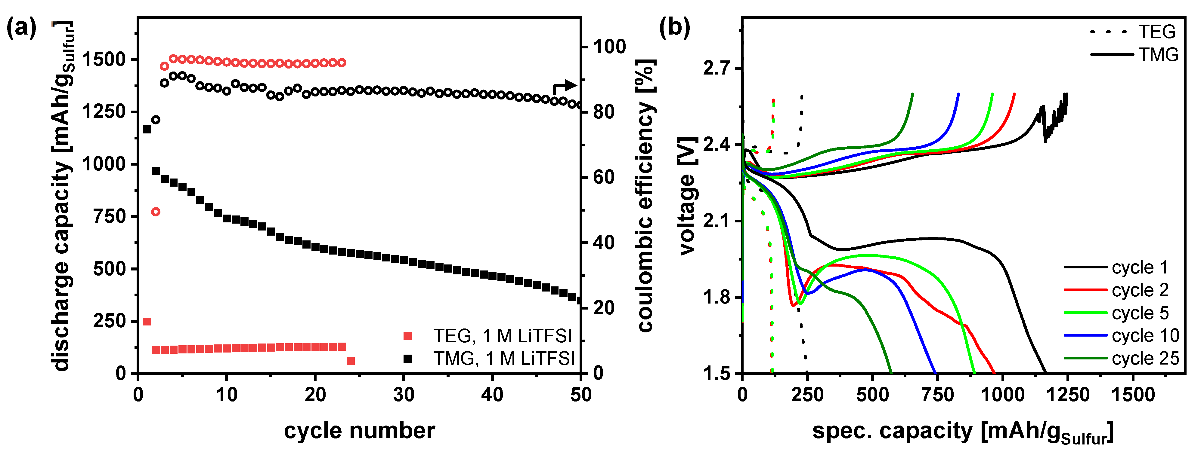
Initially performed pre-tests proved the assumption that both solvents are stable against Li as well as against PS (Figure S1, Supporting Information). Therefore, first cell tests were carried out using a typical concentration of 1 M LiTFSI with the pure solvent. The two obtained electrolytes led to completely different performances during cycling at a moderate C-Rate of 0.1, as illustrated in Figure 1. The electrolyte containing TEG displayed only a relatively low sulfur utilization of 250 mAh/g in the formation cycle (0.05 C), which decreased further to only 100 mAh/g in cycle 2. This was in stark contrast to the results of Hess et al. [38] obtained for Li-ion batteries, which shows again the completely different requirements of a complex conversion-type LSB. The reason for the poor performance is the strong overpotential, which prevents the formation of the usually observed second plateau at 2.1 V (Figure 1b). In contrast to this, the TMG-electrolyte achieved high initial capacities of around 1000 mAh/g. Nevertheless, the TMG-electrolyte also showed quite a high overpotential in the voltage profiles, especially a distinct voltage dip between the two plateaus. These results indicate that both electrolytes inhibited the kinetics of the sulfur reduction reaction. The reason for this performance might be the combination of a low PS-solubility and a low ionic conductivity. However, recently developed electrolytes show similar characteristics with better performance. Therefore, the higher viscosity of the glyoxal solvents might also be an issue, which might lead to lower cathode wettability. The coulombic efficiency (CE) was 90% for all cycles indicating a slight PS-shuttle; however, this value should not be overinterpreted as the cell was constantly degrading. In conclusion, the use of glyoxal solvent as the only solvent in LSB-electrolyte is not a viable approach due to slow kinetics and therefore high overpotential. Hence, since the solvating ability of the solvents is quite low such a poor performance was expected and further adjustment of the pristine glyoxal electrolytes, e.g., varying the LiTFSI concentration, is not effective.

3.2. Influence of Temperature on Electrolyte Performance

In order to gain a deeper understanding of these electrolytes, high temperature measurements were performed. Since room temperature performance was marked by high overpotential, leading to the conclusion of inhibited redox reaction kinetics, the increase in temperature should improve the cell conditions. Otherwise, there could be further challenges regarding the interplay of these electrolytes with the electrode materials, which were not visible by the pretests.
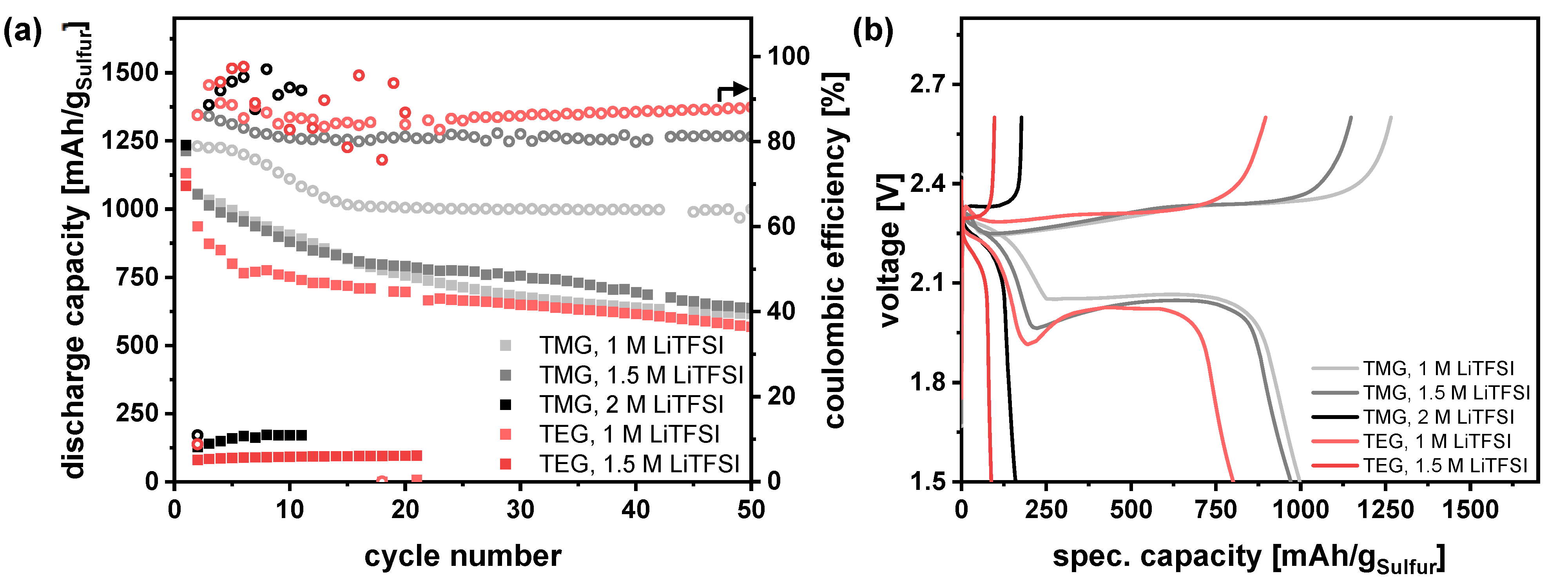
Thus, to increase the conversion kinetics, the electrolytes were evaluated at 40 °C and with varying conductive salt concentrations in combination with a sulfur cathode and a lithium anode, as depicted in Figure 2. Firstly, the same electrolytes, pure glyoxal-solvent with 1 M LiTFSI, were evaluated. The overpotential was lowered and, therefore, the kinetics significantly increased for both electrolytes. Thus, high initial capacities of over 1000 mAh/g were obtained in both cases. In the following cycles, the TMG electrolyte exhibited higher capacities than the TEG electrolyte. This is related to the shortened first plateau of this electrolyte indicating a lower sulfur utilization. This observation fits to the assumed lower solvating abilities of TEG in comparison to TMG. However, after 20 cycles, both electrolytes yielded the same sulfur utilization. Therefore, these solvents were potentially usable for LSBs, but for room temperature application, the addition of a second solvent would be necessary, as elucidated later. Regarding the CE, the increase in the temperature had a pronounced influence. In comparison to the tests at 25 °C, the CE of the TMG-electrolyte decreased by 10% to 20%, indicating that the polysulfide shuttle increased strongly. Higher temperatures intuitively increased the kinetics of desired reactions, but also of side reactions. The TEG-electrolyte also showed, despite lower solvating abilities, a CE below 90%. However, these results revealed that these glyoxal-based electrolytes offer the potential to be further developed for high temperature application. In contrast, LiNO3 –based electrolytes cannot be used at elevated temperatures due to increased gas formation in the cell whilst cycling. Thus, to decrease the shuttle problem, as well as to increase the stability of the electrolyte, the concentration of LiTFSI was adjusted. Higher concentrations of LiTFSI are known to reduce the PS-solubility and hence, the PS-shuttle. However, as it can be seen in Figure 2b, an increase from 1 M LiTFSI to 2 M LiTFSI leads to a cut-off of the second plateau for both solvents.
Since TMG shows a lower overpotential with 1 M LiTFSI, a second adjustment was performed using 1.5 M LiTFSI resulting in only a slight increase in overpotential. Thereby, the polysulfide shuttle could be reduced, since the CE was increased to 80%. However, the increase in the salt concentration did not seem to have a large influence on the capacity retention here. Presumably, the reason was the still quite low CE. Nevertheless, the results show that by adjusting the electrolyte composition, an optimal composition for specific temperature ranges was viable.

3.3. Addition of a Second Solvent—Adaption of the Electrolyte Composition

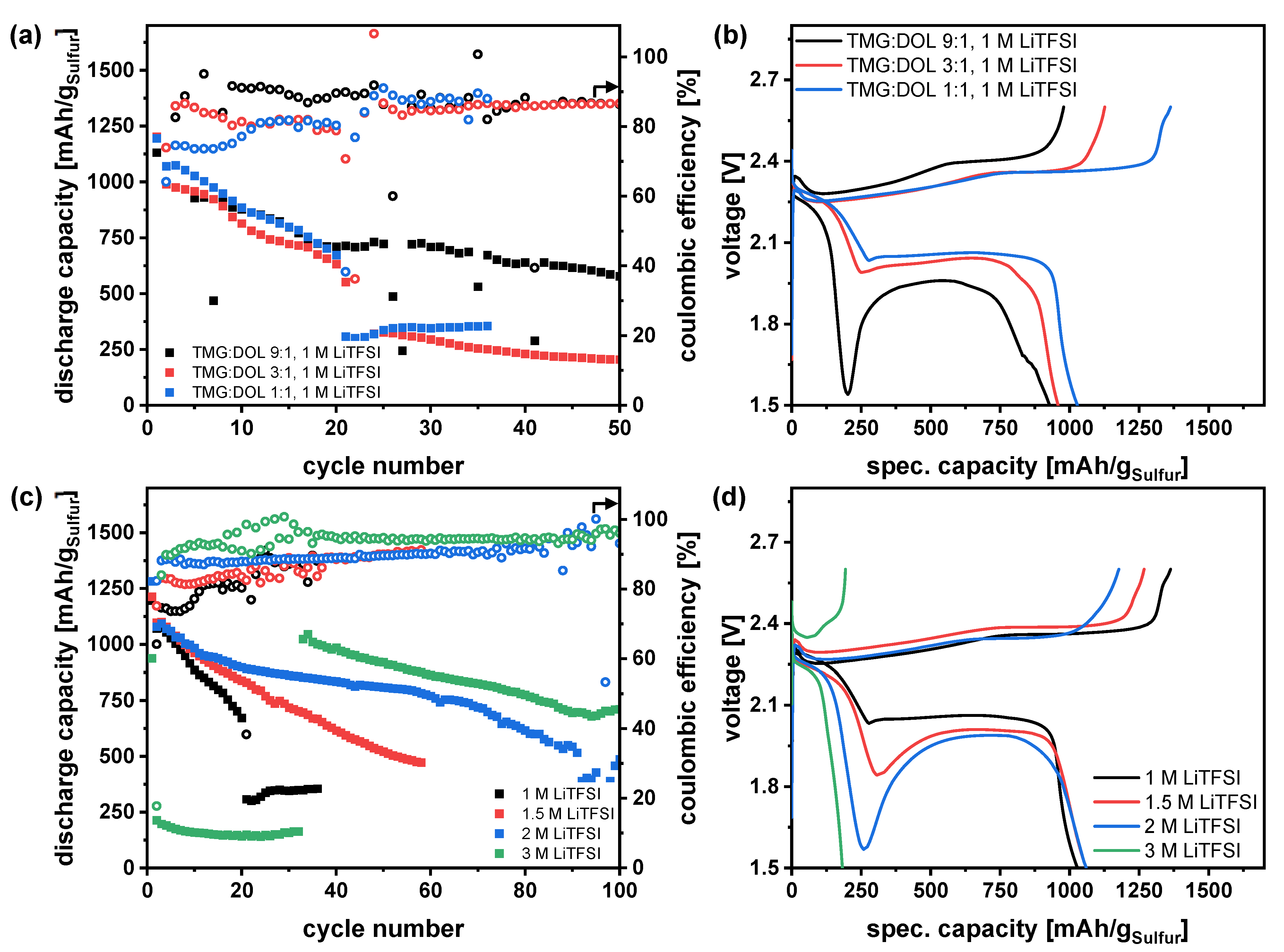
In order to improve the performance at 25 °C, the addition of a second solvent is necessary—which is the common path to improve the electrolyte performance of Li-S cells. DME and DOL are the common solvents in LSBs showing quite high solvating abilities. Among the solvent groups commonly used for LIBs, only sulfones (sulfolane, TMS) show similar solvating abilities. However, they suffer from high mass densities as well as viscosities lowering the specific energy and power density and are, therefore, not considered here. Regarding only the physical properties of DME and DOL, they should possess equal solvating abilities due to comparable dielectric constants. However, DME has higher solvating abilities due to the possibility of bidentate coordination to the Li+-ion (chelate effect). Therefore, the solvating abilities are drastically increased, which results in better salt solubility and therefore higher ionic conductivity [41]. However, the improved coordinating abilities also increase the PS solubility and consequently increase the PS-shuttle [42]. Thus, DOL is on the one hand a possibility to reduce the PS-solubility in comparison to DME, while on the other hand, it improves also the electrolyte stability against the lithium anode by a SEI-forming polymerization reaction [43,44]. Due to these properties, DOL seems to be the more promising candidate to further adjust the electrolytes, especially for electrolytes without LiNO3. Therefore, DOL was chosen as possible second solvent for glyoxal-electrolytes. As the TMG-electrolytes demonstrated more promising electrochemical performances than the TEG-analogues the focus was set on the development of TMG:DOL-electrolytes in the next section. Here, the electrolyte system was fixed to TMG:DOL as binary solvent system and LiTFSI as lithium salt. This led to only two parameters which could be varied being left, the solvent ratio and the salt concentration. First, the solvent ratio was adjusted, and the salt concentration was kept at 1 M LiTFSI to enable a sensible comparison to the so far tested systems. Various solvent ratios were considered with high TMG-content, 1:1, 3:1 and 9:1 (TMG:DOL), to possibly enable an electrolyte with reduced PS-solubility. The cycling performance of the so obtained three electrolyte systems is shown in Figure 3a,b (further voltage profiles are shown in the Supporting Information in Figure S2). For two electrolyte compositions, TMG:DOL 3:1 and 1:1, a reduced overpotential could be observed in comparison to the pure TMG-electrolyte.
Therefore, the addition of DOL successfully increased the conversion kinetics. A small addition of 10% showed no improvement of the cell overpotential as this amount of DOL was not sufficient. The decreasing voltage dip with increasing amount of DOL was the most pronounced difference between the different solvent ratios. In the literature, the dip is assigned to the maximum amount of polysulfides dissolved in the electrolyte [45], which will lead to an increased electrolyte viscosity and a decreased ionic conductivity and therefore reduced kinetics. This fits to the observed order, a low DOL-content leads to a high voltage dip due to limited electrolyte properties. In addition, it corresponds also to the observations made in Figure 3d an increasing salt concentration results in a stronger voltage dip since higher salt concentration will also negatively affect the electrolyte properties. The lack of a voltage dip between the two plateaus as well as a second plateau at 2 to 2.1 V indicate a clearly positive effect of the DOL-addition, which is quite important in terms of specific energy. Unfortunately, regarding the cycle life of the electrolyte systems no positive effect was obtained by varying the solvent ratio. Therefore, cycle life is still quite limited. In addition, TMG:DOL 9:1 showed the highest cycle life, hence it was a contrary trend to the overpotentials. This might be in correlation with the CE, which increased constantly by increasing the amount of TMG. These results confirmed the assumption of a lower PS-solubility of the glyoxal solvents in comparison to DOL. Comparing the 3:1 ratio and the 1:1 ratio in detail, the 1:1 ratio led to a slightly higher sulfur utilization as well as a slightly lower overpotential. Nevertheless, the CE of the 1:1 ratio was already quite low with values of 75% in the first cycles. A further adjustment of the solvent ratio seems to be unpromising, since increasing the DOL-content would result in an increased PS-shuttle, using the same salt concentration. To improve the limited cycle life as well as the CE the adjustment of salt concentration can be quite impactful. However, an increased salt concentration will have also an influence on other important electrolyte properties like ionic conductivity or viscosity. Therefore, the 1:1 ratio is presumably the most promising of the first considered solvent ratios for further investigations since the overpotential for higher TMG-contents (TMG:DOL 3:1) is already increased for 1 M LiTFSI. An increase in the salt concentration would further reduce the ionic conductivity and increase the viscosity, which will result in even higher overpotentials for these electrolyte compositions. The salt concentration was varied in the range of 1 M LiTFSI to 3 M LiTFSI. As discussed above, the salt concentration had a drastic influence on the electrolyte density affecting the specific energy. Thus, 3 M LiTFSI was set as an upper limit. The results (Figure 3c,d) showed a drastic influence of salt concentration on the performance, especially on the cycle life. By increasing the salt concentration stepwise to 2 M LiTFSI the cycle life continuously increased. As expected, the CE could also be improved from approx. 70% for the electrolyte with 1 M LiTFSI to 90% for the electrolyte with 2 M LiTFSI. This shows the tremendous influence of the lithium salt concentration on the PS solubility and the lithium plating/stripping kinetics (Sand`s correlation). A further increase in the salt concentration did not seem to be productive as an electrolyte with 3 M LiTFSI displayed only a very low sulfur utilization of 200 mAh/g for the first 30 cycles. The reason for this was the increasing overpotential of the cell, which increased constantly with the salt concentration, leading to a cut-off of the discharge after the first plateau. Interestingly, after 30 cycles the 3 M LiTFSI electrolyte led to high sulfur utilization. An explanation for this behavior might be the decomposition of lithium salt at the lithium anode. Therefore, the salt concentration would decrease with increasing cycling time, which will change electrolyte properties to higher ionic conductivities as well as lower viscosity. Thus, the voltage dip decreases and the second plateau is formed. Again, further voltage profiles are illustrated in the supporting information (Figure S3). Interestingly, mainly the voltage dip between the two plateaus was influenced, whereas the overpotential of the two plateaus was only slightly affected. The reason for this behavior might be an extremely high influence of the polysulfides on the electrolyte properties, especially the ionic conductivity as well as the viscosity. Unfortunately, the best so far developed system with a salt concentration of 2 M LiTFSI shows also a very strong voltage dip, which could result in a cut-off after the first plateau. Therefore, a further adjustment might be suitable to improve the kinetics of the cell, thus the overpotential, while maintaining the beneficial cycle life and coulombic efficiency. Accordingly, the DOL-content was increased to 75%. The so obtained electrolyte TMG:DOL 1:3, 2 M LiTFSI showed a superior performance in comparison to the further electrolyte systems which were considered here (Figure 4 and Figure S4). A high sulfur utilization as well as a high cycle life for a Li-S-battery with a capacity retention of 730 mAh/g after 100 cycles were obtained.
Furthermore, the CE is, for the Li-S system, relatively high, reaching values of 90%. To evaluate the influence of the TMG-solvent a reference electrolyte system, DOL with 2 M LiTFSI, was also tested under the same conditions. The results clearly show that the PS-solubility could be successfully decreased since the coulombic efficiency of the reference system is significantly lower. The higher polysulfide shuttle of the reference system also led to an increased degradation of the cell. Since the addition of DOL increased the kinetics of the TMG-electrolyte system drastically, the combination of TEG and DOL might also be a suitable solvent combination. Therefore, a TEG electrolyte with the composition TEG:DOL 1:3 with 2 M LiTFSI was also evaluated. The performance of the electrolyte is quite equal to the TMG-equivalent though. This is interesting since the CE is not influenced by the change of glyoxal solvent. In conclusion, two beneficial electrolyte compositions could be identified: TMG/TEG:DOL 1:3 with 2 M LiTFSI, showing both a significant improved performance to the reference system, pure DOL with 2 M LiTFSI. Therefore, both glyoxal-solvents are promising solvents for further electrolyte development and characterization.

3.4. Physicochemical Characterization of the Adapted Glyoxal/Dioxolane-Based Electrolytes

To gain a deeper understanding of the herein developed electrolytes, the most relevant electrolyte properties were determined, summarized in Figure 5: ionic conductivity, viscosity, density as well as the electrochemical stability window. Furthermore, depending on the application, also the thermal stability (Figure S5) can be important. Besides the promising electrolyte compositions TXG:DOL 1:3 with 2 M LiTFSI, the analogue compositions with the 1:1 ratio were also herein investigated to understand the differences of the performance. Regarding the ionic conductivity (Figure 5a) a clear trend was visible depending on the solvent ratio. As expected, the higher DOL-content of 75% (TXG:DOL 1:3) increased the ionic conductivity. Thus, the TMG containing electrolyte (TMG:DOL 1:3) showed an ionic conductivity of 5.0 mS/cm at 20 °C. Interestingly, the corresponding TEG-electrolyte exhibited only to a slightly lower value of 4.6 mS/cm. The deviation between the ionic conductivity of these two electrolytes rose with increasing temperature. This was also observed for the 1:1 ratio. These electrolytes showed lower ionic conductivities of 3.7 mS/cm (TMG:DOL) and 3.1 mS/cm (TEG:DOL), respectively. Nevertheless, all four electrolytes demonstrate promising values for LSB-application, exceeding values of recently published electrolytes, especially SPSEs [27,33,46]. The TEG-electrolytes showed an interesting behavior at higher temperatures reaching a maximum of ionic conductivity with subsequently decreasing values. This behavior might indicate a decomposition of these electrolytes, e.g., due to the occurrence of in-situ polymerization via cationic mechanisms caused by the unavoidable presence of trace Lewis acids in the salt. However, it was not observed for glyoxal-based electrolytes [37,39]. Therefore, it might be attributed to the second solvent DOL, which tends to polymerization [44]. In addition to a possible decomposition of the electrolyte also evaporation of DOL, with a boiling point of 74 °C, might be a possible explanation. However, the loss of ionic conductivity was not observed for the TMG-electrolytes here. Therefore, further analysis is necessary to understand this behavior.
The viscosity data (Figure 5b) displayed again a beneficial influence of the higher DOL-content with values of 5.0 mPa s for the TMG-electrolyte and 5.2 mPa s for the TEG-analogues. This is related to the quite high viscosity of the glyoxal-based electrolyte solvents. Regarding the 1:1 ratio, the TMG-electrolyte had a viscosity of 7.8 mPa s and the TEG a viscosity of 7.9 mPa s. Interestingly, there was again only a minor influence of the type of glyoxal solvent. The measured viscosities were also in a good range for LSB battery application [47].
The electrolyte mass density (Figure 5c) is, especially for LSBs, a very important electrolyte parameter [5,48], as light-weight electrolytes can enable high energy density cells. Here, all of the four electrolytes showed nearly the same density of 1.25 g/cm³ to 1.28 g/cm³ at 20 °C, which is not surprising since all solvents have a similar density. The obtained value was in the medium range when compared to other published electrolytes. For example, DME:DOL had a low density of 1.1 g/cm3 [27], mainly caused by the lower salt concentration but also due to the low density of DME. In contrast, high concentrated electrolytes as well as electrolytes containing fluoroethers usually possess significantly higher densities of 1.5 g/cm³ limiting the specific energy to around 250 Wh/kg [20,49].
The electrochemical stability was also evaluated in the range of 0 V to 5 V, shown in Figure 5d. In the high voltage area above 3 V all electrolytes started to decompose. Furthermore, the TEG:DOL 1:3 electrolyte showed a peak at 1 V. Nevertheless, in the usual Li-S voltage range of 1.5 V to 3 V no decomposition reactions could be observed. This measurement exemplifies the suitability of these electrolytes for LSBs. In addition to the electrochemical stability the thermal stability of the electrolytes was also investigated (Figure S5, Supporting Information). Thermogravimetric analysis was performed by heating the samples to 550 °C. A change of weight could already be observed at 50 °C with the evaporation of solvent, presumably DOL due to the lower boiling point. Reaching temperatures of 300 °C, a plateau was formed at around 40%, when probably all solvent was evaporated. At temperatures above 400 °C the salt was also decomposing. In a second experiment the electrolytes were treated with a constant temperature of 60 °C. Interestingly, the electrolytes showed a quite similar behavior with a loss of 30% to 40%. Afterwards only a low decrease in weight was observed for the following 11 h, whereas TEG showed even more promising behavior than TMG. These results underline another beneficial property of the herein presented solvents, due to the higher boiling point the safety of the battery can be increased. In conclusion, all of the four electrolytes showed promising properties for LSB-application. Nevertheless, the distinct voltage dip observed for the 1:1 ratio could not be explained by these differences since some SPSEs possessed even lower ionic conductivities without showing such a voltage profile. Since the voltage dip is ascribed in the literature to the maximum polysulfide solubility [50], the influence of polysulfides seems to be more drastic here. This is discussed in the next chapter.

3.5. Influence of Polysulfides on Electrolyte Properties and Evaluation in Li-S Pouchcells

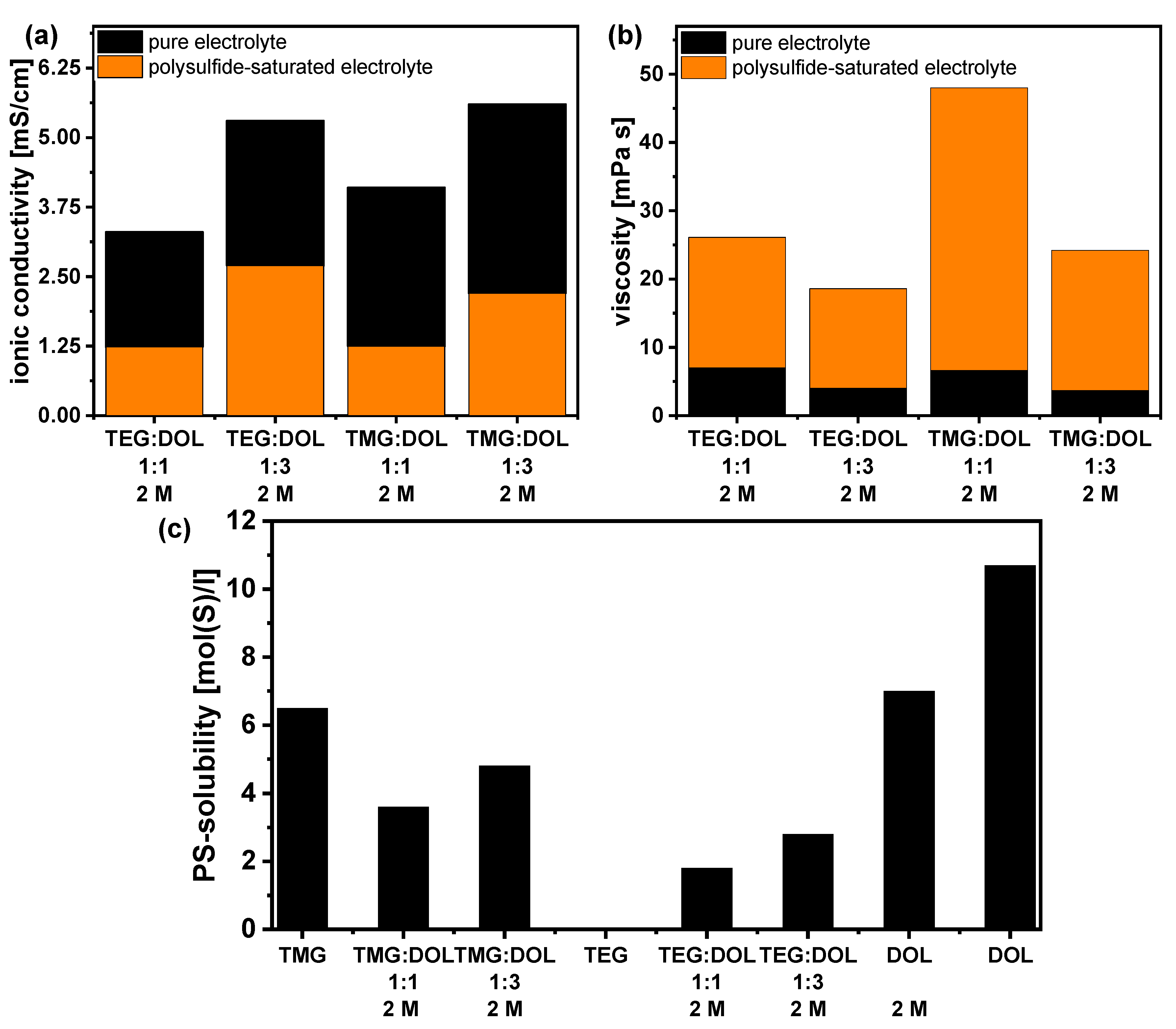
In case of LSBs it is often neglected that electrolyte properties such as ionic conductivity and viscosity might change in the cell during cycling due to the dissolution of polysulfides. This becomes even more important if low electrolyte amounts are used. E.g., DME:DOL, which has a high ionic conductivity, is at lower E:S-ratios (below 3 µL/mg-S) due to the drastic change of the electrolyte properties through the dissolution of PS clusters that drastically increase the viscosity values up to an order of magnitude [47]. Therefore, it is necessary to also determine the influence of PS on the electrolyte properties by evaluating PS saturated electrolyte solutions [47]. The results are depicted in Figure 6. Ionic conductivities, as well as the viscosities, were determined for PS solutions at 25 °C to match the temperature of the cell tests. The determination of PS saturated electrolytes properties is only meaningful at the testing temperature since a change of temperature will also influence the polysulfide solubility. Additionally, for this electrolyte system, the results showed a significant influence of PS on the electrolyte properties (Figure 6a,b).
The ionic conductivity of all four electrolyte systems was reduced to less than 50%; for example, the ionic conductivity of the pristine electrolyte TEG:DOL 1:1 with 2 M LiTFSI is 3.3 mS/cm. The saturation of the electrolyte with polysulfides led to a reduction in the ionic conductivity to 1.24 mS/cm. This still indicates quite a high PS solubility of these electrolytes. Furthermore, the viscosity of the electrolytes was even more strongly affected. However, in comparison to highly PS solvating electrolytes, such as DME:DOL, the influence of the PS was drastically reduced. This validates the beneficial impact of the glyoxal-based solvents on the electrolyte properties. Additionally, the PS solubility was determined for the pure solvents as well as for the considered electrolytes. Interestingly, the TMG-solvent showed quite a high sulfur solubility of 6.5 M, which is in stark contrast to TEG which dissolves nearly no PS (<0.1 M). However, DOL showed an even higher PS-solubility of around 11 M. It has to be noted that the determination, especially of such high amounts of PS, is quite challenging since it is not clear whether the saturated conditions are already reached. To ensure realistic conditions, the solutions were stirred for a long time with excess of Li2S and S8. For the four electrolyte systems, the PS solubility drastically decreased due to the high concentration of LiTFSI, despite the quite high contents of DOL. In contrast, the pure DOL electrolyte showed a significant higher PS-solubility of approx. 7 M. Therefore, the herein introduced glyoxal-based solvents can effectively be used to reduce the PS-solubility in the cell, which is beneficial for the ionic conductivity as well as for the viscosity. A lower viscosity will also lead to an increased cathode wettability. Nevertheless, the PS-solubilities of the TXG-electrolytes were higher than for recently reported SPSEs. Therefore, the conversion mechanism of the herein developed electrolytes is presumably more similar to electrolytes like DME:DOL with PS species dissolving in the electrolyte during cycling. Hence a dissolution-based conversion mechanism is expected rather than a quasi-solid-solid conversion mechanism. This hypothesis is supported by the CE, which is with approx. 90% quite high for LSBs, but still a little bit lower than for SPSEs like HME:DOL, reaching values of 98%, indicating a decent PS-shuttle. In addition, the voltage profiles of the TXG-electrolytes showed the typical two plateau shape with a voltage difference of approx. 0.3 V between the two plateaus [45]. On the contrary, SPSEs showed a quasi equi-potential biplateau shape during discharge [49]. A detailed study of the conversion mechanism regarding, for example the involved polysulfide species, would afford the application of operando measurements like X-ray absorption spectroscopy, which was not the scope of this work.
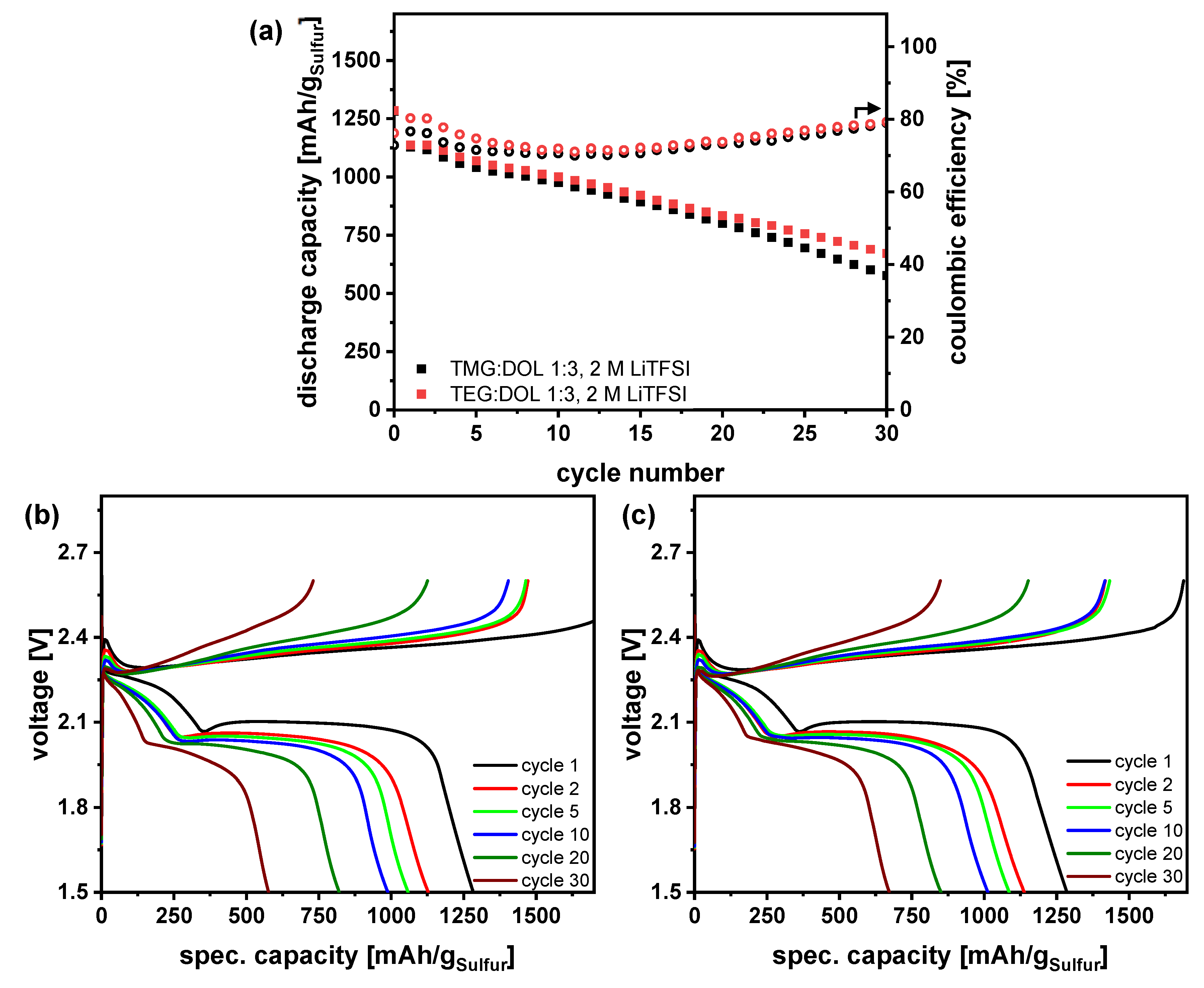
The coin cell results were quite promising for a new developed electrolyte system. Nevertheless, coin cell tests are generally performed under unrealistic conditions, especially high excess of lithium as well as higher electrolyte amounts, which will lead of course to more promising results, especially in terms of cycle life. In this work, in comparison to the literature, a relatively low E:S ratio of 7 µL/mg-S was implemented for coin cell testing which underlines the obtained results. The most promising of the developed electrolyte systems were also investigated in practical relevant pouch cells, as shown in Figure 7.
This enabled cycling under application-oriented conditions with low electrolyte amount and low lithium excess, which is not possible in coin cells. The findings gained at coin cell level can be principally transferred to five-layered pouch cells. In general, high sulfur utilizations were observed for both electrolytes, and again no difference between the TEG and the TMG electrolyte could be observed, despite the lower electrolyte amount. Regarding the voltage profiles, no differences are observed. The overpotential of the cell was also very low (0.05 V to 0.1 V regarding the second plateau of the discharge). Therefore, the herein introduced electrolytes could be successfully employed in a practically relevant battery. However, the CE was lower in comparison to the coin cell results, which was not expected since less electrolyte amount is applied here. A possible explanation for this behavior, which can be again observed for both electrolytes, might be the use of external pressure on the cell stack. This could lead to an increased PS shuttle through the reduction of diffusion path lengths. To verify this assumption a study of the influence of the external cell pressure on the electrolyte performance should be conducted in future as it is beyond the scope of this work. A more detailed study on this topic has been recently conducted by Schmidt et al. [40], revealing a complex interplay between cathode porosity, pressure application, and PS solubility of the implemented electrolytes.
Post-mortem analysis was done after the cell tests. The pouch cells were disassembled, and photos of the cell components were taken, as shown in Figure S6. As shown by the electrochemical evaluation, no difference between the lithium anodes and separators is observed. The separators showed a slight yellow coloration, due to PS residues. The surface of the lithium metal anodes is covered with decomposition products. However, all lithium anodes still had a decent morphology and were not fused with the separator, as was the case in previous studies [47].

4. Conclusions

In this work, two new glyoxal-based solvents, TMG and TEG were evaluated concerning their suitability as electrolyte solvent for LSBs. Both solvents were evaluated in LSB cells, firstly as pristine solvent, and, subsequently, as a solvent blend with DOL. Whereas the pure solvents do not seem to be suitable; due to high overpotentials during discharge, the solvent blends with DOL showed quite promising results. An optimum electrolyte composition was found to be TXG:DOL 1:3 with 2 M LiTFSI demonstrating high stability in coin cells, resulting in high cycle life as well as high CE. Thus, the PS-Shuttle could be significantly reduced by the addition of glyoxal solvents, which could be further shown by the determination of the PS solubility of the electrolytes. In pouch cells, it turned out that the PS-shuttle is still quite high. Nevertheless, the influence of PS could be drastically decreased in comparison to highly PS solvating electrolytes like DME:DOL. This might enable lower electrolyte amounts in LSB pouch cells, which should be considered in further studies. Furthermore, the use of LiNO3 is not necessary to enable stable cycling. This is an important step to fulfill the UN38.3 regulation for the shipment of Li-batteries and, consequently, an important step to the commercialization and real-world applications of Li-S-batteries.

Supplementary Materials

The following supporting information can be downloaded at: https://www.mdpi.com/article/10.3390/batteries9040210/s1. Figure S1. Stability tests of glyoxal-based solvents against lithium and polysulfides: TMG (left) and TEG (right). Figure S2. Voltage profiles of TMG:DOL electrolytes with 1 M LiTFSI: (a) TMG:DOL 1:1, (b) TMG:DOL 3:1, (c) TMG:DOL 9:1. Figure S3. Voltage profiles of TMG:DOL 1:1 with varying LiTFSI concentration: (a) 1 M, (b) 1.5 M, (c) 2 M, (d) 3 M. Figure S4. Voltage profiles of optimized electrolytes + reference: (a) TMG:DOL 1:3, 2 M LiTFSI, (b) TEG:DOL 1:3, 2 M LiTFSI, (c) DOL, 2 M LiTFSI. Figure S5. Thermogravimetric analysis of TXG:DOL solvent blends with 2 M LITFSI: (a) Temperature ramp to 550 °C, (b) Isotherme at 60 °C. Figure S6. Post Mortem Analysis of lithium sulfur pouch cells: Lithium (left) and separator (right), (a,b) cell 1 and 2 with TMG:DOL 1:3, 2 M LiTFSI, (c,d) with TEG:DOL 1:3, 2 M LiTFSI.

Author Contributions

Conceptualization, S.K. (Sebastian Kirchhoff); methodology, S.K. (Sebastian Kirchhoff), C.L.; data curation, S.K. (Sebastian Kirchhoff), C.L., P.H.; writing—original draft preparation, S.K. (Sebastian Kirchhoff); writing—review and editing, S.D., H.A., T.A., A.B.; supervision, S.K. (Stefan Kaskel), A.B.; funding acquisition, A.B. All authors have read and agreed to the published version of the manuscript.

Funding

Andrea Balducci and Christian Leibing wish to thank the Carl Zeiss Foundation for the financial support within the project “Intelligente Substrate: Schaltbare Grenzflächen auf Basis multiresponsiver Hybridmaterialien”.

Data Availability Statement

The data presented in this study are available on request from the corresponding author.

Acknowledgments

The authors are thankful for the pouch cell assembly and Post Mortem analysis by Peter Fleischer and Cathleen Tschelzek. Many thanks for electrolyte preparation and measurements go to Lisa Pillar and Anke Krawietz for cathode preparation.

Conflicts of Interest

The authors declare no conflict of interest.

References

  1. Kim, T.; Song, W.; Son, D.-Y.; Ono, L.K.; Qi, Y. Lithium-ion batteries: Outlook on present, future, and hybridized technologies. J. Mater. Chem. A 2019, 7, 2942–2964. [Google Scholar] [CrossRef]
  2. Yang, X.; Li, X.; Adair, K.; Zhang, H.; Sun, X. Structural Design of Lithium–Sulfur Batteries: From Fundamental Research to Practical Application. Electrochem. Energ. Rev. 2018, 1, 239–293. [Google Scholar] [CrossRef] [Green Version]
  3. Wang, X.; Deng, N.; Wei, L.; Yang, Q.; Xiang, H.; Wang, M.; Cheng, B.; Kang, W. Recent Progress in High-Performance Lithium Sulfur Batteries: The Emerging Strategies for Advanced Separators/Electrolytes Based on Nanomaterials and Corresponding Interfaces. Chem. Asian J. 2021, 16, 2852–2870. [Google Scholar] [CrossRef]
  4. OXIS Energy. OXIS Energy is Close to Achieving 500 Wh/kg and Is Targeting 600 Wh/kg with Solid State Lithium Sulfur Technology. Available online: https://www.prnewswire.com/news-releases/oxis-energy-is-close-to-achieving-500whkg-and-is-targeting-600whkg-with-solid-state-lithium-sulfur-technology-300990184.html (accessed on 1 November 2022).
  5. Dörfler, S.; Althues, H.; Härtel, P.; Abendroth, T.; Schumm, B.; Kaskel, S. Challenges and Key Parameters of Lithium-Sulfur Batteries on Pouch Cell Level. Joule 2020, 4, 539–554. [Google Scholar] [CrossRef] [Green Version]
  6. Angulakshmi, N.; Dhanalakshmi, R.B.; Sathya, S.; Ahn, J.-H.; Stephan, A.M. Understanding the Electrolytes of Lithium−Sulfur Batteries. Batter. Supercaps 2021, 414, 359. [Google Scholar] [CrossRef]
  7. Gupta, A.; Bhargav, A.; Manthiram, A. Highly Solvating Electrolytes for Lithium–Sulfur Batteries. Adv. Energy Mater. 2019, 9, 1803096. [Google Scholar] [CrossRef]
  8. Gupta, A.; Bhargav, A.; Manthiram, A. Evoking High Donor Number-assisted and Organosulfur-mediated Conversion in Lithium-Sulfur Batteries. ACS Energy Lett. 2021, 6, 224–231. [Google Scholar] [CrossRef]
  9. Guo, J.; Pei, H.; Dou, Y.; Zhao, S.; Shao, G.; Liu, J. Rational Designs for Lithium-Sulfur Batteries with Low Electrolyte/Sulfur Ratio. Adv. Funct. Mater. 2021, 31, 2010499. [Google Scholar] [CrossRef]
  10. Su, C.-C.; He, M.; Amine, R.; Chen, Z.; Amine, K. The Relationship between the Relative Solvating Power of Electrolytes and Shuttling Effect of Lithium Polysulfides in Lithium-Sulfur Batteries. Angew. Chem. Int. Ed Engl. 2018, 57, 12033–12036. [Google Scholar] [CrossRef]
  11. Xu, W.-T.; Peng, H.-J.; Huang, J.-Q.; Zhao, C.-Z.; Cheng, X.-B.; Zhang, Q. Towards Stable Lithium-Sulfur Batteries with a Low Self-Discharge Rate: Ion Diffusion Modulation and Anode Protection. ChemSusChem 2015, 8, 2892–2901. [Google Scholar] [CrossRef]
  12. Deng, N.; Kang, W.; Liu, Y.; Ju, J.; Wu, D.; Li, L.; Hassan, B.S.; Cheng, B. A review on separators for lithium sulfur battery: Progress and prospects. J. Power Sources 2016, 331, 132–155. [Google Scholar] [CrossRef]
  13. Pang, Q.; Liang, X.; Kwok, C.Y.; Nazar, L.F. Advances in lithium–sulfur batteries based on multifunctional cathodes and electrolytes. Nat. Energy 2016, 1, 652. [Google Scholar] [CrossRef]
  14. Chen, W.-J.; Li, B.-Q.; Zhao, C.-X.; Zhao, M.; Yuan, T.-Q.; Sun, R.-C.; Huang, J.-Q.; Zhang, Q. Electrolyte Regulation towards Stable Lithium-Metal Anodes in Lithium-Sulfur Batteries with Sulfurized Polyacrylonitrile Cathodes. Angew. Chem. Int. Ed Engl. 2020, 59, 10732–10745. [Google Scholar] [CrossRef]
  15. Aurbach, D.; Pollak, E.; Elazari, R.; Salitra, G.; Kelley, C.S.; Affinito, J. On the Surface Chemical Aspects of Very High Energy Density, Rechargeable Li–Sulfur Batteries. J. Electrochem. Soc. 2009, 156, A694. [Google Scholar] [CrossRef]
  16. Guo, W.; Zhang, W.; Si, Y.; Wang, D.; Fu, Y.; Manthiram, A. Artificial dual solid-electrolyte interfaces based on in situ organothiol transformation in lithium sulfur battery. Nat. Commun. 2021, 12, 3031. [Google Scholar] [CrossRef]
  17. Wei, J.-Y.; Zhang, X.-Q.; Hou, L.-P.; Shi, P.; Li, B.-Q.; Xiao, Y.; Yan, C.; Yuan, H.; Huang, J.-Q. Shielding Polysulfide Intermediates by an Organosulfur-Containing Solid Electrolyte Interphase on the Lithium Anode in Lithium-Sulfur Batteries. Adv. Mater. 2020, 32, e2003012. [Google Scholar] [CrossRef]
  18. Liang, X.; Wen, Z.; Liu, Y.; Wu, M.; Jin, J.; Zhang, H.; Wu, X. Improved cycling performances of lithium sulfur batteries with LiNO3-modified electrolyte. J. Power Sources 2011, 196, 9839–9843. [Google Scholar] [CrossRef]
  19. Xiong, S.; Xie, K.; Diao, Y.; Hong, X. Properties of surface film on lithium anode with LiNO3 as lithium salt in electrolyte solution for lithium–sulfur batteries. Electrochim. Acta 2012, 83, 78–86. [Google Scholar] [CrossRef]
  20. Weller, C.; Thieme, S.; Härtel, P.; Althues, H.; Kaskel, S. Intrinsic Shuttle Suppression in Lithium-Sulfur Batteries for Pouch Cell Application. J. Electrochem. Soc. 2017, 164, A3766. [Google Scholar] [CrossRef]
  21. Qu, C.; Chen, Y.; Yang, X.; Zhang, H.; Li, X.; Zhang, H. LiNO3-free electrolyte for Li-S battery: A solvent of choice with low Ksp of polysulfide and low dendrite of lithium. Nano Energy 2017, 39, 262–272. [Google Scholar] [CrossRef]
  22. Jozwiuk, A.; Berkes, B.B.; Weiß, T.; Sommer, H.; Janek, J.; Brezesinski, T. The critical role of lithium nitrate in the gas evolution of lithium–sulfur batteries. Energy Environ. Sci. 2016, 9, 2603–2608. [Google Scholar] [CrossRef] [Green Version]
  23. Liu, Y.; Elias, Y.; Meng, J.; Aurbach, D.; Zou, R.; Xia, D.; Pang, Q. Electrolyte solutions design for lithium-sulfur batteries. Joule 2021, 5, 2323–2364. [Google Scholar] [CrossRef]
  24. Cheng, L.; Curtiss, L.A.; Zavadil, K.R.; Gewirth, A.A.; Shao, Y.; Gallagher, K.G. Sparingly Solvating Electrolytes for High Energy Density Lithium–Sulfur Batteries. ACS Energy Lett. 2016, 1, 503–509. [Google Scholar] [CrossRef]
  25. Sun, K.; Wu, Q.; Tong, X.; Gan, H. Electrolyte with Low Polysulfide Solubility for Li–S Batteries. ACS Appl. Energy Mater. 2018, 1, 2608–2618. [Google Scholar] [CrossRef]
  26. Zhang, X.-Q.; Jin, Q.; Nan, Y.-L.; Hou, L.-P.; Li, B.-Q.; Chen, X.; Jin, Z.-H.; Zhang, X.-T.; Huang, J.-Q.; Zhang, Q. Electrolyte Structure of Lithium Polysulfides with Anti-Reductive Solvent Shells for Practical Lithium-Sulfur Batteries. Angew. Chem. Int. Ed Engl. 2021, 60, 15503–15509. [Google Scholar] [CrossRef]
  27. Weller, C.; Pampel, J.; Dörfler, S.; Althues, H.; Kaskel, S. Polysulfide Shuttle Suppression by Electrolytes with Low-Density for High-Energy Lithium–Sulfur Batteries. Energy Technol. 2019, 20, 9821. [Google Scholar] [CrossRef]
  28. Glaser, R.; Borodin, O.; Johnson, B.; Jhulki, S.; Yushin, G. Minimizing Long-Chain Polysulfide Formation in Li-S Batteries by Using Localized Low Concentration Highly Fluorinated Electrolytes. J. Electrochem. Soc. 2021, 168, 90543. [Google Scholar] [CrossRef]
  29. Tang, B.; Wu, H.; Du, X.; Cheng, X.; Liu, X.; Yu, Z.; Yang, J.; Zhang, M.; Zhang, J.; Cui, G. Highly Safe Electrolyte Enabled via Controllable Polysulfide Release and Efficient Conversion for Advanced Lithium-Sulfur Batteries. Small 2020, 16, e1905737. [Google Scholar] [CrossRef]
  30. Lee, C.-W.; Pang, Q.; Ha, S.; Cheng, L.; Han, S.-D.; Zavadil, K.R.; Gallagher, K.G.; Nazar, L.F.; Balasubramanian, M. Directing the Lithium-Sulfur Reaction Pathway via Sparingly Solvating Electrolytes for High Energy Density Batteries. ACS Cent. Sci. 2017, 3, 605–613. [Google Scholar] [CrossRef] [Green Version]
  31. Suo, L.; Hu, Y.-S.; Li, H.; Armand, M.; Chen, L. A new class of Solvent-in-Salt electrolyte for high-energy rechargeable metallic lithium batteries. Nat. Commun. 2013, 4, 1481. [Google Scholar] [CrossRef] [Green Version]
  32. Zheng, J.; Fan, X.; Ji, G.; Wang, H.; Hou, S.; DeMella, K.C.; Raghavan, S.R.; Wang, J.; Xu, K.; Wang, C. Manipulating electrolyte and solid electrolyte interphase to enable safe and efficient Li-S batteries. Nano Energy 2018, 50, 431–440. [Google Scholar] [CrossRef]
  33. Cuisinier, M.; Cabelguen, P.-E.; Adams, B.D.; Garsuch, A.; Balasubramanian, M.; Nazar, L.F. Unique behaviour of nonsolvents for polysulphides in lithium–sulphur batteries. Energy Environ. Sci. 2014, 7, 2697–2705. [Google Scholar] [CrossRef]
  34. Nakanishi, A.; Ueno, K.; Watanabe, D.; Ugata, Y.; Matsumae, Y.; Liu, J.; Thomas, M.L.; Dokko, K.; Watanabe, M. Sulfolane-Based Highly Concentrated Electrolytes of Lithium Bis(trifluoromethanesulfonyl)amide: Ionic Transport, Li-Ion Coordination, and Li–S Battery Performance. J. Phys. Chem. C 2019, 123, 14229–14238. [Google Scholar] [CrossRef] [Green Version]
  35. Scheers, J.; Fantini, S.; Johansson, P. A review of electrolytes for lithium–sulphur batteries. J. Power Sources 2014, 255, 204–218. [Google Scholar] [CrossRef]
  36. Cleaver, T.; Kovacik, P.; Marinescu, M.; Zhang, T.; Offer, G.J. Commercializing Lithium Sulfur Batteries: Are We Doing the Right Research? J. Electrochem. Soc. 2018, 165, A6029. [Google Scholar] [CrossRef]
  37. Heß, L.H.; Balducci, A. Glyoxal-Based Solvents for Electrochemical Energy-Storage Devices. ChemSusChem 2018, 11, 1919–1926. [Google Scholar] [CrossRef]
  38. Hess, L.H.; Wankmüller, S.; Köps, L.; Bothe, A.; Balducci, A. Stable Acetals of Glyoxal as Electrolyte Solvents for Lithium-Ion Batteries. Batteries Supercaps 2019, 2, 852–857. [Google Scholar] [CrossRef]
  39. Köps, L.; Leibing, C.; Hess, L.H.; Balducci, A. Mixtures of Glyoxylic Acetals and Organic Carbonates as Electrolytes for Lithium-Ion Batteries. J. Electrochem. Soc. 2021, 168, 10513. [Google Scholar] [CrossRef]
  40. Schmidt, F.; Korzhenko, A.; Härtel, P.; Reuter, F.S.; Ehrling, S.; Dörfler, S.; Abendroth, T.; Althues, H.; Kaskel, S. Influence of external stack pressure on the performance of Li-S pouch cell. J. Phys. Energy 2022, 4, 14004. [Google Scholar] [CrossRef]
  41. Andersen, A.; Rajput, N.N.; Han, K.S.; Pan, H.; Govind, N.; Persson, K.A.; Mueller, K.T.; Murugesan, V. Structure and Dynamics of Polysulfide Clusters in a Nonaqueous Solvent Mixture of 1,3-Dioxolane and 1,2-Dimethoxyethane. Chem. Mater. 2019, 31, 2308–2319. [Google Scholar] [CrossRef]
  42. Wang, L.; Ye, Y.; Chen, N.; Huang, Y.; Li, L.; Wu, F.; Chen, R. Development and Challenges of Functional Electrolytes for High-Performance Lithium-Sulfur Batteries. Adv. Funct. Mater. 2018, 28, 1800919. [Google Scholar] [CrossRef]
  43. Mikhaylik, Y.V.; Kovalev, I.; Schock, R.; Kumaresan, K.; Xu, J.; Affinito, J. High Energy Rechargeable Li-S Cells for EV Application: Status, Remaining Problems and Solutions. ECS Trans. 2010, 25, 23–34. [Google Scholar] [CrossRef]
  44. Barchasz, C.; Leprêtre, J.-C.; Patoux, S.; Alloin, F. Electrochemical properties of ether-based electrolytes for lithium/sulfur rechargeable batteries. Electrochim. Acta 2013, 89, 737–743. [Google Scholar] [CrossRef]
  45. Wild, M.; O’Neill, L.; Zhang, T.; Purkayastha, R.; Minton, G.; Marinescu, M.; Offer, G.J. Lithium sulfur batteries, a mechanistic review. Energy Environ. Sci. 2015, 8, 3477–3494. [Google Scholar] [CrossRef]
  46. Zhou, J.; Guo, Y.; Liang, C.; Cao, L.; Pan, H.; Yang, J.; Wang, J. A new ether-based electrolyte for lithium sulfur batteries using a S@pPAN cathode. Chem. Commun. 2018, 54, 5478–5481. [Google Scholar] [CrossRef]
  47. Boenke, T.; Kirchhoff, S.; Reuter, F.S.; Schmidt, F.; Weller, C.; Dörfler, S.; Schwedtmann, K.; Härtel, P.; Abendroth, T.; Althues, H.; et al. The role of polysulfide-saturation in electrolytes for high power applications of real world Li-S pouch cells. Nano Res. 2022. [Google Scholar] [CrossRef]
  48. Liu, T.; Li, H.; Yue, J.; Feng, J.; Mao, M.; Zhu, X.; Hu, Y.-S.; Li, H.; Huang, X.; Chen, L.; et al. Ultralight Electrolyte for High-Energy Lithium-Sulfur Pouch Cells. Angew. Chem. Int. Ed Engl. 2021, 60, 17547–17555. [Google Scholar] [CrossRef]
  49. Pang, Q.; Shyamsunder, A.; Narayanan, B.; Kwok, C.Y.; Curtiss, L.A.; Nazar, L.F. Tuning the electrolyte network structure to invoke quasi-solid state sulfur conversion and suppress lithium dendrite formation in Li–S batteries. Nat. Energy 2018, 3, 783–791. [Google Scholar] [CrossRef]
  50. Cuisinier, M.; Cabelguen, P.-E.; Evers, S.; He, G.; Kolbeck, M.; Garsuch, A.; Bolin, T.; Balasubramanian, M.; Nazar, L.F. Sulfur Speciation in Li–S Batteries Determined by Operando X-ray Absorption Spectroscopy. J. Phys. Chem. Lett. 2013, 4, 3227–3232. [Google Scholar] [CrossRef]
Scheme 1. Electrolyte compounds.
Batteries 09 00210 sch001
Figure 1. Galvanostatic cycling at 0.1 C and 25 °C of pure TMG and TEG-electrolyte with 1 M LiTFSI: (a) cycle life, (b) voltage profiles in coin cells.
Batteries 09 00210 g001
Figure 2. Galvanostatic cycling at 0.1 C and 40 °C with pure TMG/TEG-electrolyte with varying LiTFSI-concentration: (a) cycle life, (b) voltage profiles in coin cells.
Batteries 09 00210 g002
Figure 3. Galvanostatic cycling at 0.1 C and 25 °C with adjusted electrolyte compositions: influence of solvent ratio for TMG:DOL-electrolytes with 1 M LiTFSI: (a) cycle life, (b) voltage profiles of 5th cycle; influence of LiTFSI concentration for TMG:DOL 1:1: (c) cycle life, (d) voltage profiles of 5th cycle tested in coin cells.
Batteries 09 00210 g003
Figure 4. Galvanostatic cycling at 0.1 C and 25 °C of adapted glyoxal electrolytes, TXG:DOL 1:3 with 2 M LiTFSI and DOL-reference with 2 M LiTFSI, (a) cycle life, (b) voltage profiles of 5th cycle tested in coin cells.
Batteries 09 00210 g004
Figure 5. Determination of electrolyte properties: (a) Ionic conductivities determined with a cell, consisting of two parallel platinized Pt-electrodes, (b) viscosities determined with a rotational viscometer, (c) densities determined with an oscillating U-tube densitometer at varying temperatures, (d) electrochemical stability tests performed in a three electrode cell using a Pt-disk as working electrode, an oversized activated carbon electrode as counter electrode and a Ag-wire as reference electrode.
Batteries 09 00210 g005
Figure 6. Influence of polysulfides on electrolyte properties at 25 °C: (a) ionic conductivities, (b) viscosities, (c) polysulfide solubility of solvents and electrolytes.
Batteries 09 00210 g006
Figure 7. Galvanostatic cycling at 0.1 C and 25 °C in 5-layered Li-S pouchcells of adapted glyoxal-based electrolytes TXG:DOL 1:3 with 2 M LiTFSI with an E:S-ratio of 4.5 µL/mg-S: (a) cycle life, (b) voltage profiles of TMG:DOL, 2 M LiTFSI, (c) TEG:DOL 1:3, 2 M LiTFSI.
Batteries 09 00210 g007
Disclaimer/Publisher’s Note: The statements, opinions and data contained in all publications are solely those of the individual author(s) and contributor(s) and not of MDPI and/or the editor(s). MDPI and/or the editor(s) disclaim responsibility for any injury to people or property resulting from any ideas, methods, instructions or products referred to in the content.