Article

Interface Engineering of a NASICON-Type Electrolyte Using Ultrathin CuS Film for Lithium Metal Batteries

1
Key Laboratory for Liquid-Solid Structural Evolution & Processing of Materials (Ministry of Education), Research Center for Carbon Nanomaterials, School of Materials Science and Engineering, Shandong University, Jinan 250061, China
2
State Key Lab of Advanced Welding and Joining, School of Materials Science and Engineering, Harbin Institute of Technology (Shenzhen), Shenzhen 518055, China
*
Authors to whom correspondence should be addressed.
Batteries 2023, 9(4), 194; https://doi.org/10.3390/batteries9040194
Submission received: 6 February 2023 / Revised: 20 March 2023 / Accepted: 20 March 2023 / Published: 24 March 2023
(This article belongs to the Special Issue Advances in Rechargeable Li Metal Batteries)

Abstract

:
NASICON-type Li1.5Al0.5Ge1.5(PO4)3 (LAGP) is a remarkable solid-state electrolyte due to its high ionic conductivity and excellent air stability. However, the weak LAGP|Li interfacial compatibility (e.g., chemical instability of LAGP with Li metal and lithium dendrite growth) limits its practical application. Herein, an ultrathin CuS layer was fabricated on the surface of the LAGP electrolyte by magnetron sputtering (MS). Then, an in situ Li2S/Cu nano-layer formed via the conversion reaction between CuS and molten Li was constructed at the LAGP|Li interface. The Li2S/Cu nano-layer enables effective hindering of the reduction reactions of LAGP with Li metals and the suppression of lithium dendrite growth. The assembled Li symmetric battery with the Li2S/Cu@LAGP electrolyte shows a promising critical current density (CCD) of 0.6 mA cm−2 and a steady battery operation for over 700 h. Furthermore, the full LiFePO4 battery comprising the Li2S/Cu@LAGP electrolyte shows excellent capacity retention of 94.5% after 100 cycles, providing an appropriate interface modification strategy for all-solid-state Li metal batteries.

Graphical Abstract

1. Introduction

Developing lithium-ion batteries with a high energy density and high levels of safety is urgently needed given the rapid development of new energy vehicles and portable electronic devices [1,2]. Lithium metal anode is regarded as the optimal anode material due to its higher capacity and lower reduction potential compared to graphite anodes [3,4]. However, lithium dendrite growth is hard to avoid for lithium metal batteries in the case of organic liquid electrolytes, which further leads to poor cycle life and safety risks [5,6,7]. To circumvent these limitations, solid-state lithium metal batteries (SSLMBs) have aroused tremendous interest.
As a critical component in SSLMBs, a wide variety of solid-state electrolytes have been developed over the past few decades. Compared to polymeric solid-state electrolytes, inorganic solid-state electrolytes (including perovskite-type [2], NASICON-type [8], garnet-type [9], and sulfide-type [10], etc.) have been intensively investigated due to their superior mechanical and thermal stability, as well as their relatively high room temperature ionic conductivity. In particular, the NASICON-type Li1.5Al0.5Ge1.5(PO4)3 (LAGP) electrolyte is particularly favored due to its excellent air stability and high ionic conductivity (>10−4 S cm−1), offering the potential for large-scale production in less restrictive environmental conditions [11,12,13]. However, insufficient contact and undesirable side reactions between LAGP and the lithium metal anode cause tremendous interfacial resistance and dendritic Li, which severely damages battery performance and limits practical production applications [14,15]. LAGP, in particular, is thought to be unstable in its reactivity to the Li metal. The electrons obtained by LAGP from the Li anode cause a partial reduction of Ge4+ to Ge2+ or Ge0 on the LAGP side, resulting in higher interphase electronic conductivity [12,16]. This allows for rapid electron transport through the interface to the LAGP electrolyte, resulting in constant electrolyte consumption [17]. In addition, the reduction of Ge4+ results in the presence of an interfacial phase, which causes the LAGP to become mechanically unstable [18]. Upon the formation of mechanical cracks, ion transport is impeded [18,19,20]. In addition to causing electrolyte cracking, the high electronic conductivity at the Li/LAGP interface tends to lead to undesirable Li dendrites at the Li/LAGP interface as well as at the electrolyte grain boundaries. Such filamentous Li dendrites are highly reactive and will react with the electrolyte LAGP, which further accelerates the side reactions [17]. In summary, the chemical and mechanical incompatibility of LAGP with Li leads to the limitation of the electrochemical window, the increase in interfacial resistance, and the generation of cracks at the LAGP|Li interface. Therefore, improving the LAGP|Li interface’s performance is crucial to the development of high-performance solid-state Li metal batteries.
To address this issue, a variety of interfacial layers have been constructed to address the interface between the NASICON-type solid-state electrolyte and the lithium metal anode, which can be mainly classified as an ion-conductive layer, electron-conductive layer, or a mixed ion/electron-conductive layer (MCL) [21,22,23,24]. Lithiophilic alloy layers, such as Ge [25], Al [26], and Zn [27], were reported to be electronic conductors that can enhance the compatibility of Li on the new face and reduce the interfacial resistance. Hu et al. [28] proposed a method of depositing a 20-nm thin Pt layer onto the Li6.75La3Zr1.75Ta0.25O12 (LLZTO) electrolyte by magnetron sputtering (MS). The formed Li–Pt alloy significantly improved the interface compatibility, reducing the interface impedance by 21 times to only 9 Ω. He et al. [29] applied an Li–Ag alloy instead of Li metal as the anode material to improve the interface compatibility of solid electrolytes. The symmetrical battery assembled with 1-μm Li@Ag can cycle stably for more than 1000 h at an areal capacity of 1 mAh cm−2. Despite being able to provide a uniform lithium-ion flow, the Li-rich alloy with high electronic conductivity could not completely hinder undesirable reduction reactions between LAGP and Li metal [30,31]. Unlike electronic conductors, ionic conductors (e.g., polymer coatings [32,33], Li3N [34], LiF [35], etc.) have been validated as an intermediate layer to prevent side reactions. However, the insufficient mechanical strength of the organic coating makes it hard to resist the penetration of lithium dendrites. Moreover, it has been observed that electrically insulated ionic conductor layers exhibit a large interfacial impedance, leading to an increase in overpotential during cycling and, ultimately, cell failure [18,36]. Both high Li+ conductivity and electronic conductivity at the interface are necessary to obtain the stable cyclic performance of SSLMBs [37,38,39]. Therefore, MCL seems to be a promising candidate. Sun et al. [34] reported a Li3N/Cu-based MCL, which effectively reduces interfacial resistance and improves the cycle life span by over 1000 h. Similarly, Liu et al. [40] also constructed an MCL of Li2S/Mo to enable enhanced close contact of lithium with a critical current density (CCD) up to 2.2 mA cm−2. In addition, Zhang et al. [41] obtained a SnS@LLZTO electrolyte prepared by a liquid deposition method, and then in situ MCL was constructed with Li2S/LixSn by using conversion reactions. These Li-symmetric cells with Li2S/LixSn-based MCL showed a low interfacial resistance of 47 Ω cm2. Thus, SSLMBs can benefit from the extensive knowledge of preventing reduction reactions and dendritic issues in liquid-based cells by Li2S/Li3N-rich SEIs. To this end, there is still an urgent need for the effective construction of MCLs for stable interfaces and practical applications.
In this paper, we provide an ultrathin CuS film coated on the LAGP electrolyte by using the MS method due to its high repetition rate and accurate thickness control. Then, a Li2S/Cu-mixed nano-interlayer was formed in situ via a simple conversion reaction between the ultrathin CuS film and molten lithium metal at 200 °C (Figure 1). The nano-interlayer can improve the LAGP electrolyte in close contact with the lithium metal and enable stable interfaces for the suppression of side reactions and lithium dendrites. Among them, Li2S has a high Li+ conductivity (close to 10−5 S cm−1) at room temperature, which facilitates fast Li+ transmission at the interface. The well-dispersed Cu nanoparticles play a role in guiding the homogeneous electronic field distribution and buffering the volume change during charging and discharging processes. As a result, the lithium plating–stripping behavior of symmetric cells and LiFePO4/Li full cells is outstanding and remains stable over time.

2. Materials and Methods

2.1. Synthesis of LAGP Pellets

In this paper, LAGP was purchased from Hefei Kejing. In general, 500 mg of LAGP pristine powder was placed into a mold, cold-pressed into pellets, and finally formed into dense LAGP pellets via annealing in a muffle furnace at 900 °C for 8 h. Then, both sides of the LAGP pellets were ground by using 400-, 800-, and 1500-mesh sandpapers to remove impurities on the surface. The thickness of the acquired LAGP pellets is ~800 μm, and the above-obtained ceramic pellets were stored in an Ar-filled glove box for further use.

2.2. Preparation of CuS Film Attached to the LAGP Pellet by MS

In this study, ultrathin CuS films were deposited on the surface of LAGP pellets using the magnetron sputtering (MS) method under vacuum conditions of less than 10−4 Pa. The target distance was 5 cm. The sputter parameters were a power of 80 W and a pressure of 1.0 Pa. By adjusting the sputtering time, LAGP pellets coated with different thicknesses could be obtained. The thicknesses of CuS@LAGP@CuS and CuS@LAGP with optimized parameters were 850 μm and 900 μm, respectively. Moreover, these prepared pellets were used for the Li-symmetric cell and Li|CuS@LAGP|LFP full cell, respectively. The Li metal needed to be polished to wipe off the oxide layer on the surface to avoid the introduction of impurities during the reaction. Subsequently, the Li2S/Cu nano-interlayer was obtained by heating the CuS@LAGP pellet and fresh Li metal (10 mm diameter) to 230 °C for 2 min in an Ar-filled glove box. In order to achieve intimate contact between CuS and the Li metal, the lithium foil was pre-attached onto both sides or onto one side of the modified LAGP pellet before heating.

2.3. SSLMB Assembly

Using LFP as the cathode, fresh Li metal (100 μm) was attached to the CuS@LAGP pellet as an anode and the electrolyte to assemble the full cells. Moreover, they were assembled in a standard CR2032 coin cell. Similarly, the full cell using the pristine LAGP electrolyte was also assembled in a standard CR2032 coin cell. The cathode was prepared by mixing LFP, super P, and poly-vinylidene fluoride (PVDF) in an appropriate amount of N-Methyl-2-pyrrolidone (NMP) at a mass ratio of 8:1:1. The well-mixed size was then coated on aluminum foil and heated to 110 °C for 12 h of drying. The cathode electrode piece that was obtained had an active material loading of 2.5 mg cm−2. The theoretical specific capacity of LFP is 170 mAh g−1. In particular, 7 μL of commercial liquid electrolyte (1 M LiPF6 in ethylene carbonate (EC)/diethyl carbonate (DEC), 1:1 v/v) was dropped towards the cathode in two types of full cells to enable rapid Li+ transport on the cathode side. Two types of full cells without liquid electrolytes at the cathode side were also assembled to verify the feasibility of the CuS@LAGP electrolyte.

2.4. Material Characterizations

X-ray diffraction (XRD) patterns of the modified LAGP pellets were collected in the regular range of 10°~90° on a Bruker D8 Advance. The atomic force microscopy (AFM) method was selected to measure the thickness of CuS films on JPK NanowizardRII. In order to measure the ionic conductivity of the prepared LAGP electrolytes, a silver coating was deposited on both sides of the LAGP pellet as block electrodes.
The calculation formula for ionic conductivity is as follows:
σ = L S R
where σ is the ionic conductivity, L represents the thickness of the prepared electrolyte, and S is the area of the electrolyte pellet.
A HITACHI SU8010 field emission scanning electron microscope was used to characterize the morphologies of the Li metal, LAGP pellet, and LFP cathode. X-ray photoelectron spectroscopy (XPS) was performed on Thermo Fisher to obtain the spectra.

2.5. Electrochemical Measurement

Electrochemical impedance spectroscopy (EIS) tests of the core-cell batteries were performed on the Autolab electrochemical workstation in a frequency ranging from 1.0 MHz to 0.01 Hz using an amplitude of 10 mV. NOVA was used to fit and analyze the impedance spectra.
The lithium transference number (tLi+) was measured via chronoamperometry and EIS tests before and after the polarization with the Li-symmetric cell. The calculation formula is as follows [42,43]:
t L i + = I s Δ V I 0 R 0 I 0 Δ V I s R s
where I0 and IS are the initial and steady-state DC currents; R0 and RS are the interfacial resistance of the cell before and after polarization, respectively; and ΔV is the applied voltage (10 mV).
All the assembled batteries above rested for 12 h before testing. The critical current density (CCD) was measured with the time control method (1 h) at a current range of 0.05~0.6 mA cm−2. The galvanostatic charge–discharge of coin cells was conducted on a LAND-CT2001A multichannel battery test system. The full cells with the LFP cathode and Li anode were performed using a voltage range of 2.5~4.0 V. The above electrochemical measurements were carried out with a constant testing temperature of 25 °C.

3. Results and Discussion

3.1. Morphology and Structure of CuS@LAGP Pellets

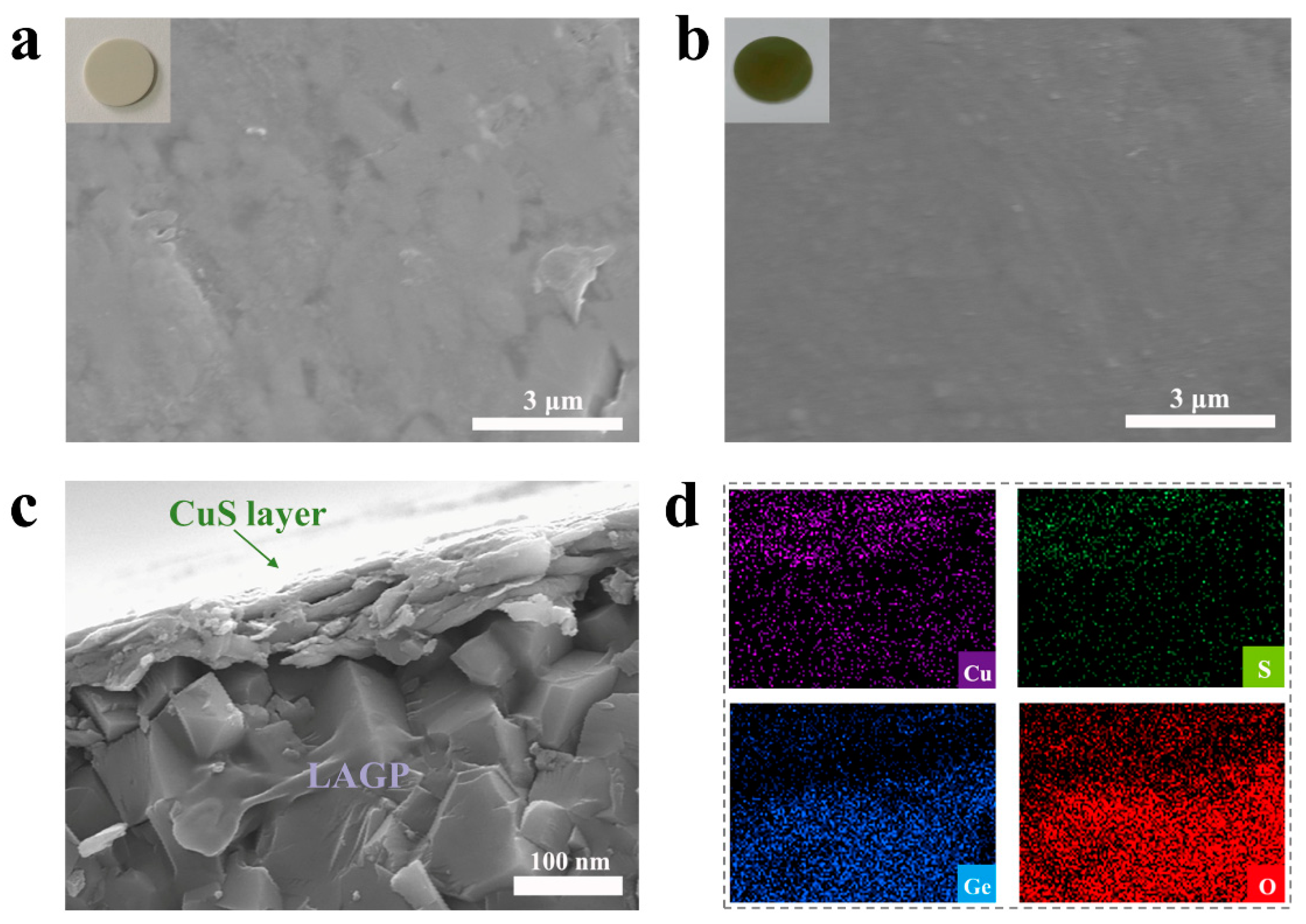
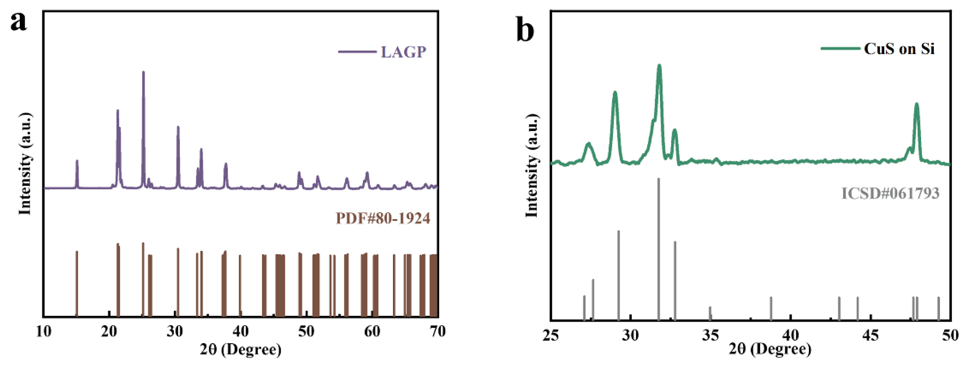
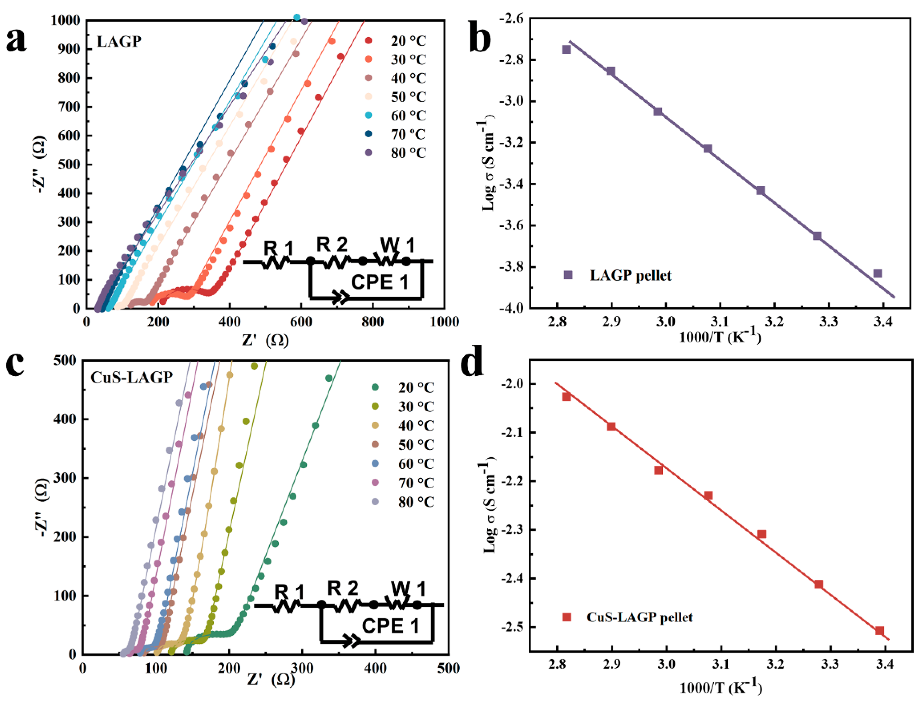
The ceramic LAGP electrolyte pellet was synthesized based on previous work [34,40]. As depicted in the inset of Figure 2a, the obtained LAGP electrolyte pellet is ivory white in color, and its planar SEM image shows that the surface scratches and holes can still be observed on the surface of the LAGP pellet even after grinding and polishing. From Supplementary Material Figure S1, the obtained LAGP electrolyte exhibits densely packed LAGP particles with a clear grain boundary. The LAGP’s surface was covered entirely with CuS particles via the MS method. Moreover, its color changed from ivory white to olive green, as shown in the inserted optical photograph of Figure 2b. The planar SEM of the CuS-coated LAGP pellet shows a dense, flat surface that can enhance the interface contact between the LAGP electrolyte and Li metal (Figure 2b). It can be observed that the LAGP surface is completely covered with an ultrathin and dense CuS film, while the Cu and S elements show a uniform distribution, indicating a successful deposition process (Figure 2c,d). By adjusting the sputtering time, CuS films of varying thicknesses can be deposited. To verify the phase’s purity, the XRD tests were carried out on the LAGP pellet and the ultrathin CuS film-coated silicon (Si) plate, as shown in Figure 3. It can be observed that all diffraction peaks match well with the LiGe2(PO4)3 phase (PDF# 80-1924) without impurities (Figure 3a), and the XRD pattern in Figure 3b matches the hexagonal CuS (JCPDS#06-0464), indicating excellent crystallinity. The ionic conductivity of the prepared bare LAGP pellets was 2.5 × 10⁻⁴ S cm−1 at 25 °C with an activation energy of 0.37 eV. Moreover, the temperature dependence of the ionic conductivity was in accordance with the Arrhenius equation (Figure 4a,b). As indicated in Figure 4c, the CuS@LAGP electrolyte delivers an excellent ionic conductivity of 3.1 × 10⁻⁴ S cm−1 at 25 °C, and the temperature dependence of ionic conductivity follows Arrhenius’ law, which enables the rapid transport of Li ions through the CuS@LAGP electrolyte. The lithium transference numbers for pristine LAGP and CuS@LAGP electrolyte were also measured, which were 0.96 and 0.98, respectively (Figure S2). By adjusting the sputtering time, CuS films of varying thicknesses can be deposited. The CuS@LAGP|Li symmetric batteries were assembled, in which the CuS@LAGP pellets were obtained at various sputtering times, and their electrochemical performances were evaluated. The EIS test reveals that the interfacial resistance reaches a minimum of 330 Ω when the sputtering time is 10 min (Figure S3). The thickness at 10 min of sputtering time was 50 nm as determined by the AFM method, which can be verified in Figure 2c (Figure S4 and Table S1).

3.2. Interface Stability of Li2S/Cu@LAGP

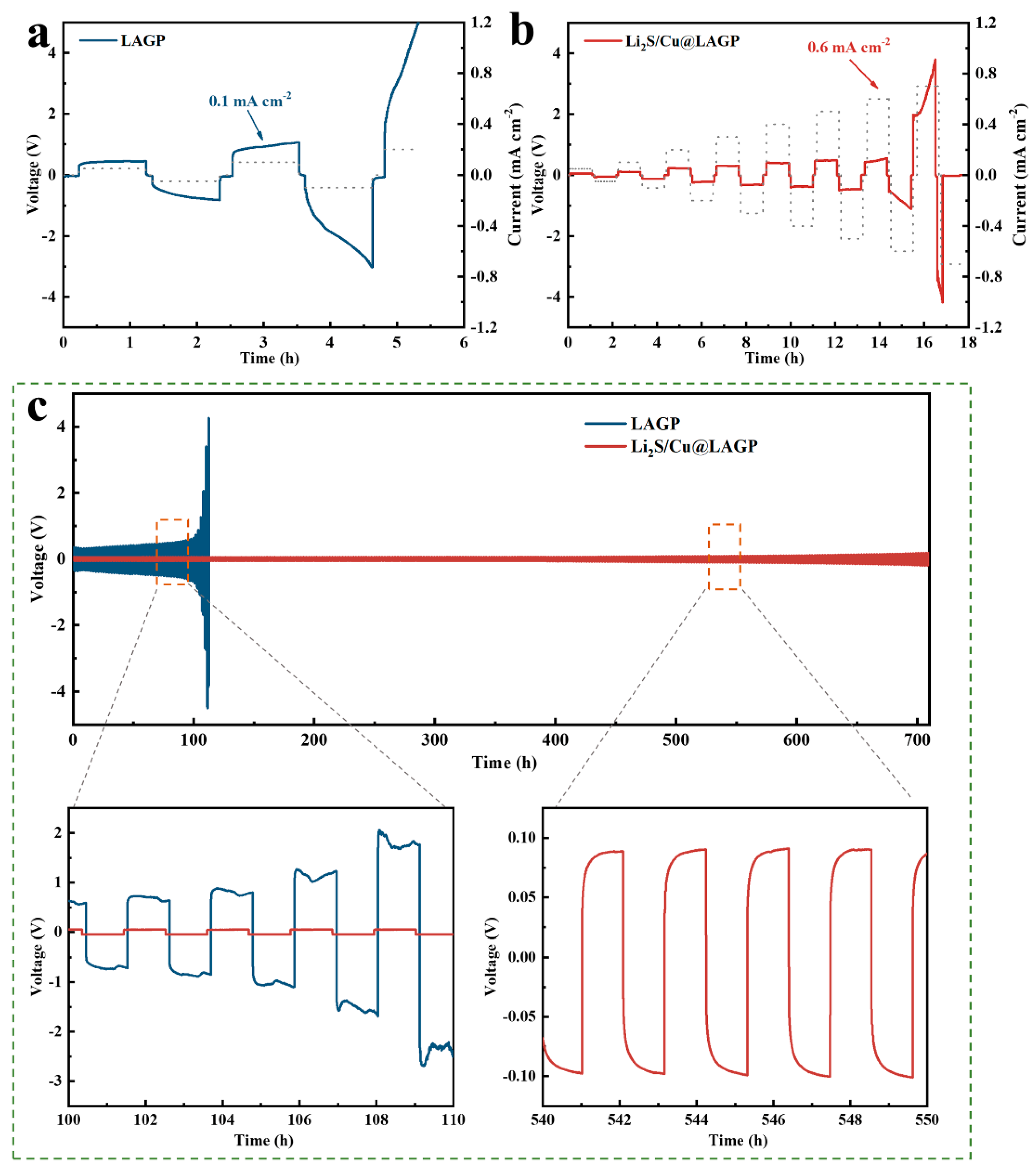
CCD is usually defined as the current density when the cell is short-circuited, which can effectively characterize the Li|LAGP interfacial stability and its ability to suppress lithium dendrites [44]. The results shown in Figure 5a demonstrate that the CCD is just 0.1 mA cm−2 for the Li|LAGP|Li cell because of the rough point–point contact and inevitable reduction reaction at the interface. In comparison, the CCD of the Li|Li2S/Cu@LAGP|Li cell can increase to 0.6 mA cm−2 (Figure 5b). Before a significant polarization suddenly occurs, the Li|Li2S/Cu@LAGP|Li cell’s voltage profile is stable and smooth. The improvement in CCD is ascribed to the synergistic effect of the ion-conducting Li2S network and electron-conducting Cu nanoparticles. More specifically, the uniformly dispersed Cu nanoparticles guide an even electric field, which avoids lithium dendrite growth during Li plating. Meanwhile, Li2S has a high ionic conductivity, providing a smooth conduit for effective Li+ transmission at the interface [34,40].
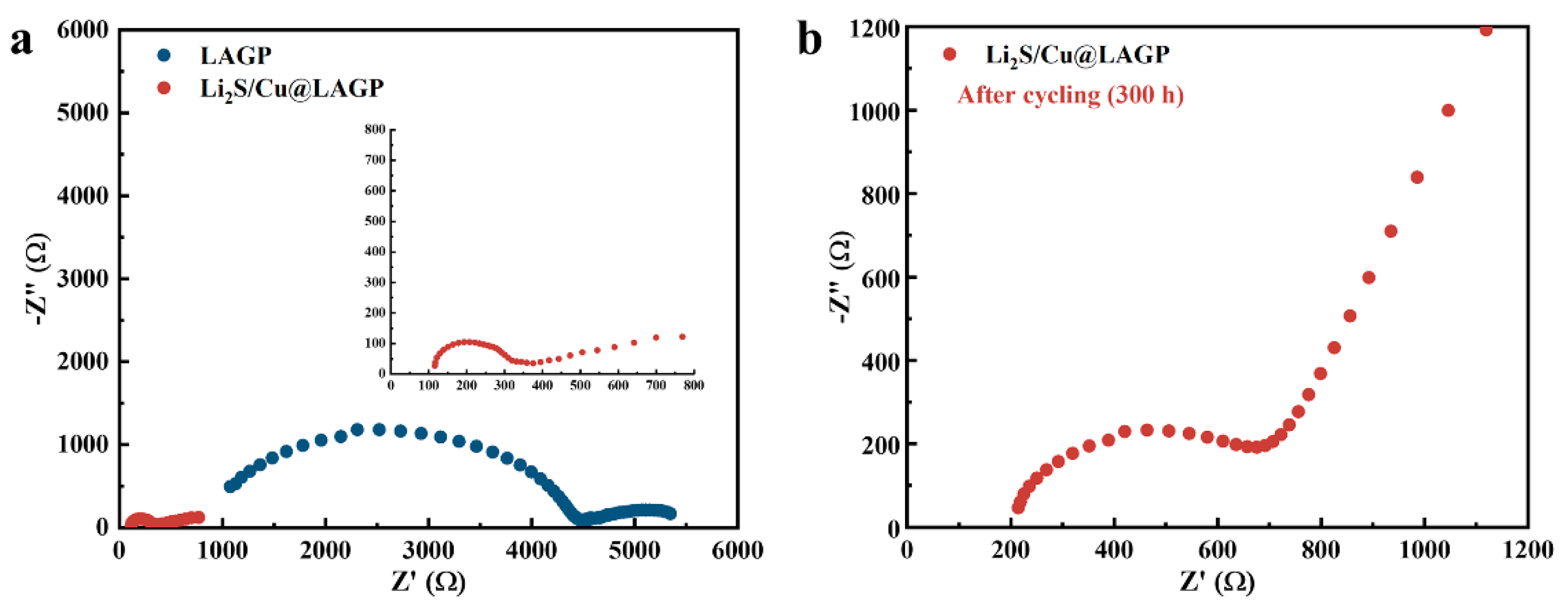
To further understand the interfacial stability, galvanostatic cycling at 25 °C was performed on both types of Li-symmetric cells. Figure 5c demonstrates that at 0.1 mA cm−2 (0.1 mA h cm−2), the overpotential of the pristine LAGP symmetric cell reaches as high as 0.3 V in the first plating/stripping cycle, followed by a significant increase in overpotential with respect to the cycling duration, and the cell breaks down after 110 h. This is due to the inhomogeneous lithium deposition behavior at the LAGP|Li interface. In contrast, the overpotential of the Li|Li2S/Cu@LAGP|Li symmetric cell is only 46 mV with a smooth and stable overpotential plateau after cycling for 110 h, and the modified Li-symmetric cell can cycle steadily for over 700 h of 80 mV at 0.1 mA cm−2. The improved cycling stability is mainly due to the improved contact in the Li2S/Cu mixed conductive interphase, which prevents the LAGP electrolyte from being reduced, thus ensuring rapid and reversible Li+ transport without being lost by lithium dendrites. The Nyquist plot of the pristine LAGP symmetric cell in Figure 6a shows a large semicircle due to the incompatible interface between the LAGP and Li metal. The LAGP|Li single interfacial resistance is high and measures up to 2250 Ω, which is due to the point–point contact at the interface. In contrast, the interfacial resistance of the modified Li2S/Cu@LAGP symmetric cell is dramatically lowered to 170 Ω. The considerable decrease in interfacial resistance is attributable to the highly strong wetting interactions between the Li2S/Cu conductive nano-layer and Li metal. Moreover, Figure 6b shows that the interfacial resistance of the modified Li2S/Cu@LAGP symmetric cell slightly increases to 350 Ω after 300 h of cycling, confirming the superior compatibility of the modified Li2S/Cu@LAGP|Li interface.
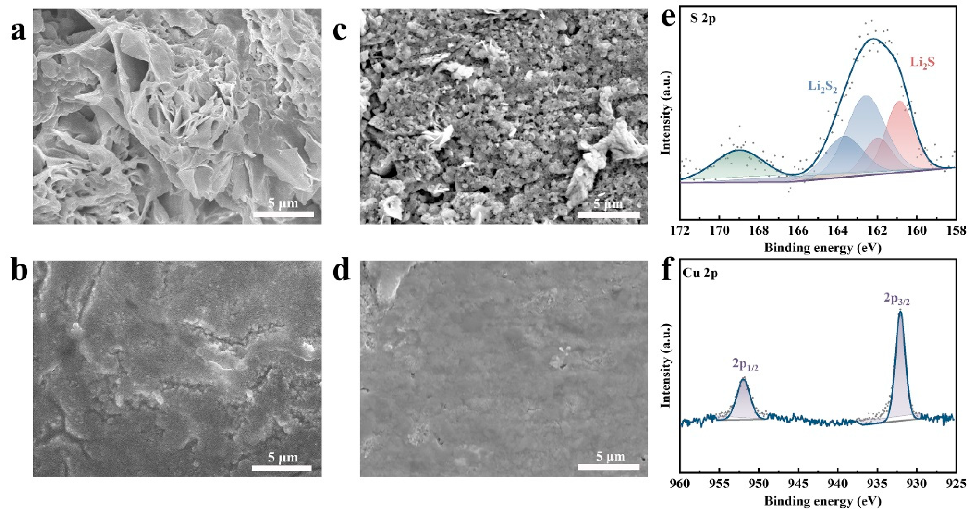
To gain insight into the stability of the interface, postmortem SEM and XPS analyses were carried out to understand the steadiness of the Li2S/Cu@LAGP|Li interface after cycling. As shown in Figure 7a, compared with fresh lithium foil (Figure S5), the Li metal recovered from the Li|LAGP|Li cell shows a highly rough and uneven surface after cycling for 50 cycles. In addition, a large amount of dead Li and obvious cracks can be found on the surface, which is the result of the uneven lithium deposition at the LAGP|Li interface. Similarly, the surface of the bare LAGP pellet after cycling shows visible holes and cracks, implying the severe breakdown of the crystal structure of the LAGP pellet (Figure 7c). The severely destroyed LAGP pellet is due to the reduction reaction of the LAGP pellet and Li metal, which leads to large local stress and further induces crack generation. The severe roughness of the Li metal and the LAGP’s structure results in enormous interfacial resistance and interfacial mechanical failure, which leads to uneven Li deposition and the production of dead Li. By contrast, Figure 7b, d show that the surfaces of the post-cycle Li metal and LAGP pellet disassembled from the Li|Li2S/Cu@LAGP|Li symmetric cell remain flat and smooth, and the resultant high-resolution mapping displays a homogeneous distribution of Cu and S elements (Figure S6), which reveals the effective suppression of side reactions and lithium dendrite growth by the Li2S/Cu nano-layer. The composition of the interfacial layer was analyzed by X-ray photoelectron spectroscopy (XPS) measurements. As shown in Figure 7e, the peak near 169.1 eV probably corresponds to sulfate caused by air pollution. The other two red peaks at 161.6 eV and 160.2 eV belong to Li2S, indicating a conversion reaction between CuS and Li, with additional small amounts of Li2S2 (at 162.8 eV and 164.0 eV) [45]. The 953.0 eV and 933.2 eV in the Cu 2p spectra are attributed to Cu particles. As shown in Figure S7, for the Ge 3d XPS spectrum of the post-cycled bare LAGP pellet, it can be observed that the binding energy of the Ge 3d peak shifts from 32.5 eV to 29.1 eV, showing that the Ge4+ in pristine LAGP was reduced to Ge0 by the Li metal. However, for the CuS-modified LAGP pellet, the signal from Ge4+ exhibits no obvious migration towards a lower binding energy after 50 cycles, proving the barrier protection effect of the Li2S/Cu nano-layer. These data indicate the conversion reaction between CuS and Li metal, and the obtained robust interface remains dynamically stable during long electrochemical cycles [46]. This in situ-formed Li2S/Cu nano-layer can effectively inhibit the LAGP pellet from being reduced and allow a uniform Li+ flux.

3.3. Electrochemical Performance of SSLMBs

To further verify the function of the Li2S/Cu nano-layer in promoting a close interface contact and its feasibility with respect to practical applications, full cells were fabricated to measure electrochemical properties. LiFePO4 (LFP, surface loading ≈ 2.5 mg cm−2) was selected as the cathode active material due to its good cyclic and safety properties. Figure 8a shows the schematic diagram of the full cell’s structure, using LFP as the cathode material, Li metal as the anode, and the CuS-modified (or not) LAGP pellet as the solid-state electrolyte. In particular, we dripped 7 μL of commercial liquid electrolyte to improve the Li+ cathode’s transmission. As shown in Figure 8b, the Li|Li2S/Cu@LAGP|LFP full cell reaches a discharge capacity of 147 mAh g−1 at 0.1 C after the initial three cycles of the activation process. Capacity retention remains at 94.5% after 100 cycles, and the Coulombic efficiency is always kept above 98.5% during the repeating Li plating/stripping process. As shown in Figure 8c, a representative charge and discharge voltage plateau in the charge/discharge curves can be observed, and the polarization voltage of the Li|Li2S/Cu@LAGP|LFP cell hardly increases with cycling. The substantially overlapping curves indicate that the Li2S/Cu nano-layer promotes the formation of an intimate interface, which can lower the interfacial resistance and realize the efficient and stable transfer of Li+. By comparison, the Li|LAGP|LFP cell shows notably poorer cycle performance (Figure 8d). The initial discharge is only 109.3 mAh g−1 at 0.1 C, and the capacity retention drops to only 59.6% after 50 cycles, which is primarily due to the LAGP|Li interface’s poor contact and the lithium depletion caused by continuous side reactions. The rapid capacity decay of the pristine full cell is consistent with the electrochemical behavior of Li-symmetric cells. The charge/discharge curves at the LAGP|Li interface also exhibit increased voltage polarization and voltage fluctuation, indicating rough contact and the occurrence of undesirable reduction reactions at the Li|LAGP interface. The Li|Li2S/Cu@LAGP|LFP also shows an excellent discharge capacity of 146.7 mAh g−1, 138.1 mAh g−1, 127.5 mAh g−1, and 112.4 mAh g−1 at 0.1, 0.2, 0.3, 0.5, and 1 C, respectively. Moreover, it can recover to 142.5 mAh g−1 at 0.1 C after rate cycling. The excellent cyclic and rate performance is mainly ascribed to the good interfacial compatibility and the dendrite-free plating/stripping process. However, the discharge capacity of Li|LAGP|LFP cells was only 113.3 mAh g−1, 93.8 mAh g−1, 71.9 mAh g−1, and 41.8 mAh g−1 when the rate increased to 0.2 C, 0.3 C, 0.5 C, and 1 C, respectively. Furthermore, the Li|LAGP|LFP cell’s capacity recovered to only 100.9 mAh g−1 when the rate returned to 0.1 C. The rapid capacity attenuation at a high rate is due to the substantial interfacial resistance and unstable interface between the LAGP electrolyte and Li anode. The SEM and XPS analyses were also carried out on post mortem LFP electrodes. As shown in Figure 9, the morphologies of LFP show no apparent differences when disassembled from the two types of full cells. Moreover, the signals of Fe2+ in two types of full cells exhibit no obvious migration, which indicates that capacity fading is mainly due to serious side reactions between the Li metal and the LAGP electrolyte (Figure 9c,d). To verify the feasibility of the construction of the Li2S/Cu nano-layer for SSLMBs, the two types of full cells were tested without liquid electrolytes added to the cathode side (Figure 10). The Li|Li2S/Cu@LAGP|LFP shows a stable discharge capacity of 140 mAh g−1 after 23 cycles, while the full cell without the Li2S/Cu nano-layer exhibits a rapidly declining discharge capacity because of the incompatible interface. Moreover, the resistance of the Li|LAGP|LFP cell sharply increased to 8100 Ω after 23 cycles. However, the resistance of the Li|Li2S/Cu@LAGP|LFP cell only slightly increased to 1085 Ω. The above results indicate that the modification of the mixed conductive Li2S/Cu nano-layer at the Li|LAGP interface is necessary and beneficial.

4. Conclusions

In summary, an intimate and continuous Li2S/Cu nano-interlayer was constructed to provide intimate contact between the LAGP electrolyte and Li metal via a facile conversion reaction. The ultrathin CuS film was coated on the surface of the LAGP pellet by MS. The Li2S with high Li+ conductivity acts as a fast ion channel, ensuring reversible and rapid Li+ transport at the interface, while well-dispersed Cu particles homogenize the electron field at the interface. The cooperative effect of Cu and Li2S enables the dendrite-free invertible Li plating/stripping process, decreases interfacial resistance, and suppresses reduction reactions at the interfaces. As a result, the CCD of Li|Li2S/Cu@LAGP|Li cells increased to 0.6 mA cm−2. The modified symmetric cells can also cycle stably over 600 h with a low overpotential (~80 mV) at 0.1 mA cm−2. The Li|Li2S/Cu@LAGP|LFP full cell shows obviously enhanced rate performances and long cycle performances (with 94.5% capacity retention after 100 cycles). These outstanding electrochemical properties suggest the feasibility of the smartly developed Li2S/Cu nano-interlayer for the improvement of interfacial compatibility. Our results highlight the feasibility of the smartly developed superior interface between the Li metal and SSEs for SSLMBs.

Supplementary Materials

The following supporting information can be downloaded at: https://www.mdpi.com/article/10.3390/batteries9040194/s1, Figure S1: SEM image of the fabricated LAGP pellet; Figure S2: Polarization curves of the LAGP and CuS@LAGP pellet and inset are the impedance spectras of the Li symmetric cell before and after polarization, respectively; Figure S3: Impedance spectra of CuS@LAGP/Li symmetric cells with various sputtering times; Figure S4: AFM images of the CuS membrane at the edge region of different sputtering times and its corresponding height profiles; Figure S5: Top-view SEM image of fresh lithium foil; Figure S6: The high-resolution mapping of Cu and S elements on post-cycle LAGP pellets; Figure S7: Ge 3d XPS spectrum of the post-cycled bare LAGP pellet and CuS@LAGP pellet; Table S1. Average sputtering rate test data of the CuS target under the condition of 80W of power at room temperature.

Author Contributions

Conceptualization, S.Z.; Data curation, S.Z.; Formal analysis, D.L.; Funding acquisition, L.Z., L.C. and G.M.; Investigation, S.Z.; Methodology, D.L.; Project administration, L.Z., L.C. and G.M.; Resources, D.L., J.L. and G.Z.; Supervision, L.Z., L.C. and G.M.; Validation, D.L.; Visualization, S.Z.; Writing—original draft, S.Z.; Writing—review and editing, S.Z., D.L., L.Z., J.L., G.Z., L.C. and G.M. All authors have read and agreed to the published version of the manuscript.

Funding

This research was funded by the High-level Talents’ Discipline Construction Fund of Shandong University: 31370089963078; and the School Research Startup Expenses of Harbin Institute of Technology (Shenzhen): DD29100027.

Data Availability Statement

Data sharing not applicable.

Conflicts of Interest

The authors declare no conflict of interest.

References

  1. Chiang, Y.-M. Building a Better Battery. Science 2010, 330, 1485–1486. [Google Scholar] [CrossRef] [PubMed]
  2. Zhao, Q.; Stalin, S.; Zhao, C.Z.; Archer, L.A. Designing solid-state electrolytes for safe, energy-dense batteries. Nat. Rev. Mater. 2020, 5, 229–252. [Google Scholar] [CrossRef]
  3. Kamaya, N.; Homma, K.; Yamakawa, Y.; Hirayama, M.; Kanno, R.; Yonemura, M.; Kamiyama, T.; Kato, Y.; Hama, S.; Kawamoto, K.; et al. A lithium superionic conductor. Nat. Mater. 2011, 10, 682–686. [Google Scholar] [CrossRef] [PubMed]
  4. Mauger, A.; Julien, C.M.; Paolella, A.; Armand, M.; Zaghib, K. Building Better Batteries in the Solid State: A Review. Materials 2019, 12, 3892. [Google Scholar] [CrossRef] [PubMed] [Green Version]
  5. Zhang, X.; Wang, A.; Liu, X.; Luo, J. Dendrites in Lithium Metal Anodes: Suppression, Regulation, and Elimination. Acc. Chem. Res. 2019, 52, 3223–3232. [Google Scholar] [CrossRef]
  6. Mauger, A.; Armand, M.; Julien, C.M.; Zaghib, K. Challenges and issues facing lithium metal for solid-state rechargeable batteries. J. Power Source 2017, 353, 333–342. [Google Scholar] [CrossRef] [Green Version]
  7. Liang, X.; Pang, Q.; Kochetkov, I.R.; Sempere, M.S.; Huang, H.; Sun, X.; Nazar, L.F. A facile surface chemistry route to a stabilized lithium metal anode. Nat. Energy 2017, 2, 17119. [Google Scholar] [CrossRef]
  8. Hou, M.J.; Liang, F.; Chen, K.F.; Dai, Y.N.; Xue, D.F. Challenges and perspectives of NASICON-type solid electrolytes for all-solid-state lithium batteries. Nanotechnology 2020, 31, 132003. [Google Scholar] [CrossRef]
  9. Badami, P.; Weller, J.M.; Wahab, A.; Redhammer, G.; Ladenstein, L.; Rettenwander, D.; Wilkening, M.; Chan, C.K.; Kannan, A.N.M. Highly Conductive Garnet-Type Electrolytes: Access to Li6.5La3Zr1.5Ta0.5O12 Prepared by Molten Salt and Solid-State Methods. ACS Appl. Mater. Interfaces 2020, 12, 48580–48590. [Google Scholar] [CrossRef]
  10. Lau, J.; DeBlock, R.H.; Butts, D.M.; Ashby, D.S.; Choi, C.S.; Dunn, B.S. Sulfide Solid Electrolytes for Lithium Battery Applications. Adv. Energy Mater. 2018, 8, 1800933. [Google Scholar] [CrossRef] [Green Version]
  11. Wu, N.; Chien, P.-H.; Li, Y.; Dolocan, A.; Xu, H.; Xu, B.; Grundish, N.S.; Jin, H.; Hu, Y.-Y.; Goodenough, J.B. Fast Li+ Conduction Mechanism and Interfacial Chemistry of a NASICON/Polymer Composite Electrolyte. J. Am. Chem. Soc. 2020, 142, 2497–2505. [Google Scholar] [CrossRef] [PubMed]
  12. Tian, H.K.; Jalem, R.; Gao, B.; Yamamoto, Y.; Muto, S.; Sakakura, M.; Iriyama, Y.; Tateyama, Y. Electron and Ion Transfer across Interfaces of the NASICON-Type LATP Solid Electrolyte with Electrodes in All-Solid-State Batteries: A Density Functional Theory Study via an Explicit Interface Model. Acs Appl. Mater. Interfaces 2020, 12, 54752–54762. [Google Scholar] [CrossRef]
  13. Zhang, S.; Zeng, Z.; Zhai, W.; Hou, G.; Chen, L.; Ci, L. Bifunctional In Situ Polymerized Interface for Stable LAGP-Based Lithium Metal Batteries. Adv. Mater. Interfaces 2021, 8, 210072. [Google Scholar] [CrossRef]
  14. Anantharamulu, N.; Rao, K.K.; Rambabu, G.; Kumar, B.V.; Radha, V.; Vithal, M. A wide-ranging review on Nasicon type materials. J. Mater. Sci. 2011, 46, 2821–2837. [Google Scholar] [CrossRef]
  15. Lee, W.; Tamura, S.; Imanaka, N. New Calcium Ion Conducting Solid Electrolyte with NASICON-type Structure. Chem. Lett. 2017, 46, 1486–1489. [Google Scholar] [CrossRef]
  16. He, L.; Sun, Q.; Chen, C.; Oh, J.A.S.; Sun, J.; Li, M.; Tu, W.; Zhou, H.; Zeng, K.; Lu, L. Failure Mechanism and Interface Engineering for NASICON-Structured All-Solid-State Lithium Metal Batteries. ACS Appl. Mater. Interfaces 2019, 11, 20895–20904. [Google Scholar] [CrossRef]
  17. Yu, Q.; Han, D.; Lu, Q.; He, Y.-B.; Li, S.; Liu, Q.; Han, C.; Kang, F.; Li, B. Constructing Effective Interfaces for Li1.5Al0.5Ge1.5(PO4)3 Pellets to Achieve Room-Temperature Hybrid Solid-State Lithium Metal Batteries. ACS Appl. Mater. Interfaces 2019, 11, 9911–9918. [Google Scholar] [CrossRef]
  18. Kim, H.-S.; Oh, Y.; Kang, K.H.; Kim, J.H.; Kim, J.; Yoon, C.S. Characterization of Sputter-Deposited LiCoO2 Thin Film Grown on NASICON-type Electrolyte for Application in All-Solid-State Rechargeable Lithium Battery. ACS Appl. Mater. Interfaces 2017, 9, 16063–16070. [Google Scholar] [CrossRef] [PubMed]
  19. Zou, Z.; Ma, N.; Wang, A.; Ran, Y.; Song, T.; He, B.; Ye, A.; Mi, P.; Zhang, L.; Zhou, H.; et al. Identifying Migration Channels and Bottlenecks in Monoclinic NASICON-Type Solid Electrolytes with Hierarchical Ion-Transport Algorithms. Adv. Funct. Mater. 2021, 31, 202107747. [Google Scholar] [CrossRef]
  20. Guhl, C.; Fingerle, M.; Hausbrand, R. Process related effects upon formation of composite electrolyte interfaces: Nitridation and reduction of NASICON-type electrolytes by deposition of LiPON. J. Power Source 2017, 362, 299–307. [Google Scholar] [CrossRef]
  21. Zhang, X.-Q.; Li, T.; Li, B.-Q.; Zhang, R.; Shi, P.; Yan, C.; Huang, J.-Q.; Zhang, Q. A Sustainable Solid Electrolyte Interphase for High-Energy-Density Lithium Metal Batteries Under Practical Conditions. Angew. Chem. Int. Ed. 2020, 59, 3252–3257. [Google Scholar] [CrossRef] [PubMed]
  22. Zhang, S.; Liang, T.; Wang, D.; Xu, Y.; Cui, Y.; Li, J.; Wang, X.; Xia, X.; Gu, C.; Tu, J. A Stretchable and Safe Polymer Electrolyte with a Protecting-Layer Strategy for Solid-State Lithium Metal Batteries. Adv. Sci. 2021, 8, 2003241. [Google Scholar] [CrossRef]
  23. Zeng, Z.; Wang, S.; Cheng, J.; Hou, G.M.; Li, D.P.; Han, G.F.; Ci, L.J. Spontaneous In Situ Surface Alloying of Li-Zn Derived from a Novel Zn2+-Containing Solid Polymer Electrolyte for Steady Cycling of Li Metal Battery. ACS Sustain. Chem. Eng. 2021, 9, 4282–4292. [Google Scholar] [CrossRef]
  24. Pan, J.; Peng, H.L.; Yan, Y.A.; Bai, Y.Z.; Yang, J.; Wang, N.N.; Dou, S.X.; Huang, F.Q. Solid-state batteries designed with high ion conductive composite polymer electrolyte and silicon anode. Energy Storage Mater. 2021, 43, 165–171. [Google Scholar] [CrossRef]
  25. Liu, Y.J.; Li, C.; Li, B.J.; Song, H.C.; Cheng, Z.; Chen, M.R.; He, P.; Zhou, H.S. Germanium Thin Film Protected Lithium Aluminum Germanium Phosphate for Solid-State Li Batteries. Adv. Energy Mater. 2018, 8, 1702374. [Google Scholar] [CrossRef]
  26. Zhong, H.; Sang, L.; Ding, F.; Song, J.; Mai, Y. Conformation of lithium-aluminium alloy interphase-layer on lithium metal anode used for solid state batteries. Electrochim. Acta 2018, 277, 268–275. [Google Scholar] [CrossRef]
  27. Ci, N.; Zhang, L.; Li, J.; Li, D.; Cheng, J.; Sun, Q.; Xi, Z.; Xu, Z.; Zhao, G.; Ci, L. In situ construction of a flexible interlayer for durable solid-state lithium metal batteries. Carbon 2022, 187, 13–21. [Google Scholar] [CrossRef]
  28. Liao, Y.-K.; Tong, Z.; Fang, C.-C.; Liao, S.-C.; Chen, J.-M.; Liu, R.-S.; Hu, S.-F. Extensively Reducing Interfacial Resistance by the Ultrathin Pt Layer between the Garnet-Type Solid-State Electrolyte and Li-Metal Anode. ACS Appl. Mater. Interfaces 2021, 13, 56181–56190. [Google Scholar] [CrossRef]
  29. Li, M.; Zhou, D.; Wang, C.; Weng, W.; Jiang, M.; Liu, G.; Yao, X.; He, H. In Situ Formed Li-Ag Alloy Interface Enables Li10GeP2S12-Based All-Solid-State Lithium Batteries. ACS Appl. Mater. Interfaces 2021, 13, 50076–50082. [Google Scholar] [CrossRef]
  30. Liu, H.; Cheng, X.-B.; Huang, J.-Q.; Yuan, H.; Lu, Y.; Yan, C.; Zhu, G.-L.; Xu, R.; Zhao, C.-Z.; Hou, L.-P.; et al. Controlling Dendrite Growth in Solid-State Electrolytes. ACS Energy Lett. 2020, 5, 833–843. [Google Scholar] [CrossRef]
  31. Zhang, Z.; Chen, S.; Yao, X.; Cui, P.; Duan, J.; Luo, W.; Huang, Y.; Xu, X. Enabling high-areal-capacity all-solid-state lithium-metal batteries by tri-layer electrolyte architectures. Energy Storage Mater. 2020, 24, 714–718. [Google Scholar] [CrossRef]
  32. Yan, Y.; Ju, J.; Dong, S.; Wang, Y.; Huang, L.; Cui, L.; Jiang, F.; Wang, Q.; Zhang, Y.; Cui, G. In Situ Polymerization Permeated Three-Dimensional Li+-Percolated Porous Oxide Ceramic Framework Boosting All Solid-State Lithium Metal Battery. Adv. Sci. 2021, 8, 2003887. [Google Scholar] [CrossRef] [PubMed]
  33. Cai, D.; Wu, X.; Xiang, J.; Li, M.; Su, H.; Qi, X.; Wang, X.; Xia, X.; Gu, C.; Tu, J. Ionic-liquid-containing polymer interlayer modified PEO-based electrolyte for stable high-voltage solid-state lithium metal battery. Chem. Eng. J. 2021, 424, 130522. [Google Scholar] [CrossRef]
  34. Huo, H.Y.; Chen, Y.; Li, R.Y.; Zhao, N.; Luo, J.; da Silva, J.G.P.; Mucke, R.; Kaghazchi, P.; Guo, X.X.; Sun, X.L. Design of a mixed conductive garnet/Li interface for dendrite-free solid lithium metal batteries. Energy Environ. Sci. 2020, 13, 127–134. [Google Scholar] [CrossRef]
  35. Guo, Q.P.; Han, Y.; Wang, H.; Xiong, S.Z.; Sun, W.W.; Zheng, C.M.; Xie, K. Flame Retardant and Stable Li1.5Al0.5Ge1.5(PO4)3-Supported Ionic Liquid Gel Polymer Electrolytes for High Safety Rechargeable Solid-State Lithium Metal Batteries. J. Phys. Chem. C 2018, 122, 10334–10342. [Google Scholar] [CrossRef]
  36. Huo, H.; Gao, J.; Zhao, N.; Zhang, D.; Holmes, N.G.; Li, X.; Sun, Y.; Fu, J.; Li, R.; Guo, X.; et al. A flexible electron-blocking interfacial shield for dendrite-free solid lithium metal batteries. Nat. Commun. 2021, 12, 176. [Google Scholar] [CrossRef] [PubMed]
  37. Nolan, A.M.; Wachsman, E.D.; Mo, Y. Computation-guided discovery of coating materials to stabilize the interface between lithium garnet solid electrolyte and high-energy cathodes for all-solid-state lithium batteries. Energy Storage Mater. 2021, 41, 571–580. [Google Scholar] [CrossRef]
  38. Park, K.; Yu, B.-C.; Jung, J.-W.; Li, Y.; Zhou, W.; Gao, H.; Son, S.; Goodenough, J.B. Electrochemical Nature of the Cathode Interface for a Solid-State Lithium-Ion Battery: Interface between LiCoO2 and Garnet-Li7La3Zr2O12. Chem. Mater. 2016, 28, 8051–8059. [Google Scholar] [CrossRef]
  39. Mueller, M.; Schmieg, J.; Dierickx, S.; Joos, J.; Weber, A.; Gerthsen, D.; Ivers-Tiffee, E. Reducing Impedance at a Li-Metal Anode/Garnet-Type Electrolyte Interface Implementing Chemically Resolvable In Layers. ACS Appl. Mater. Interfaces 2022, 14, 14739–14752. [Google Scholar] [CrossRef]
  40. Fu, J.; Yu, P.; Zhang, N.; Ren, G.; Zheng, S.; Huang, W.; Long, X.; Li, H.; Liu, X. In situ formation of a bifunctional interlayer enabled by a conversion reaction to initiatively prevent lithium dendrites in a garnet solid electrolyte. Energy Environ. Sci. 2019, 12, 1404–1412. [Google Scholar] [CrossRef]
  41. Zhao, B.; Ma, W.; Li, B.; Hu, X.; Lu, S.; Liu, X.; Jiang, Y.; Zhang, J. A fast and low-cost interface modification method to achieve high-performance garnet-based solid-state lithium metal batteries. Nano Energy 2022, 91, 106643. [Google Scholar] [CrossRef]
  42. Evans, J.; Vincent, C.A.; Bruce, P.G. Electrochemical measurement of transference numbers in polymer electrolytes. Polymer 1987, 28, 2324–2328. [Google Scholar] [CrossRef]
  43. Zugmann, S.; Fleischmann, M.; Amereller, M.; Gschwind, R.M.; Wiemhoefer, H.D.; Gores, H.J. Measurement of transference numbers for lithium ion electrolytes via four different methods, a comparative study. Electrochim. Acta 2011, 56, 3926–3933. [Google Scholar] [CrossRef]
  44. Wang, T.; Duan, J.; Zhang, B.; Luo, W.; Ji, X.; Xu, H.; Huang, Y.; Huang, L.; Song, Z.; Wen, J.; et al. A self-regulated gradient interphase for dendrite-free solid-state Li batteries. Energy Environ. Sci. 2022, 15, 1325–1333. [Google Scholar] [CrossRef]
  45. Chen, H.; Pei, A.; Lin, D.; Xie, J.; Yang, A.; Xu, J.; Lin, K.; Wang, J.; Wang, H.; Shi, F.; et al. Uniform High Ionic Conducting Lithium Sulfide Protection Layer for Stable Lithium Metal Anode. Adv. Energy Mater. 2019, 9, 1900858. [Google Scholar] [CrossRef]
  46. Yan, C.; Cheng, X.-B.; Yao, Y.-X.; Shen, X.; Li, B.-Q.; Li, W.-J.; Zhang, R.; Huang, J.-Q.; Li, H.; Zhang, Q. An Armored Mixed Conductor Interphase on a Dendrite-Free Lithium-Metal Anode. Adv. Mater. 2018, 30, 1804461. [Google Scholar] [CrossRef]
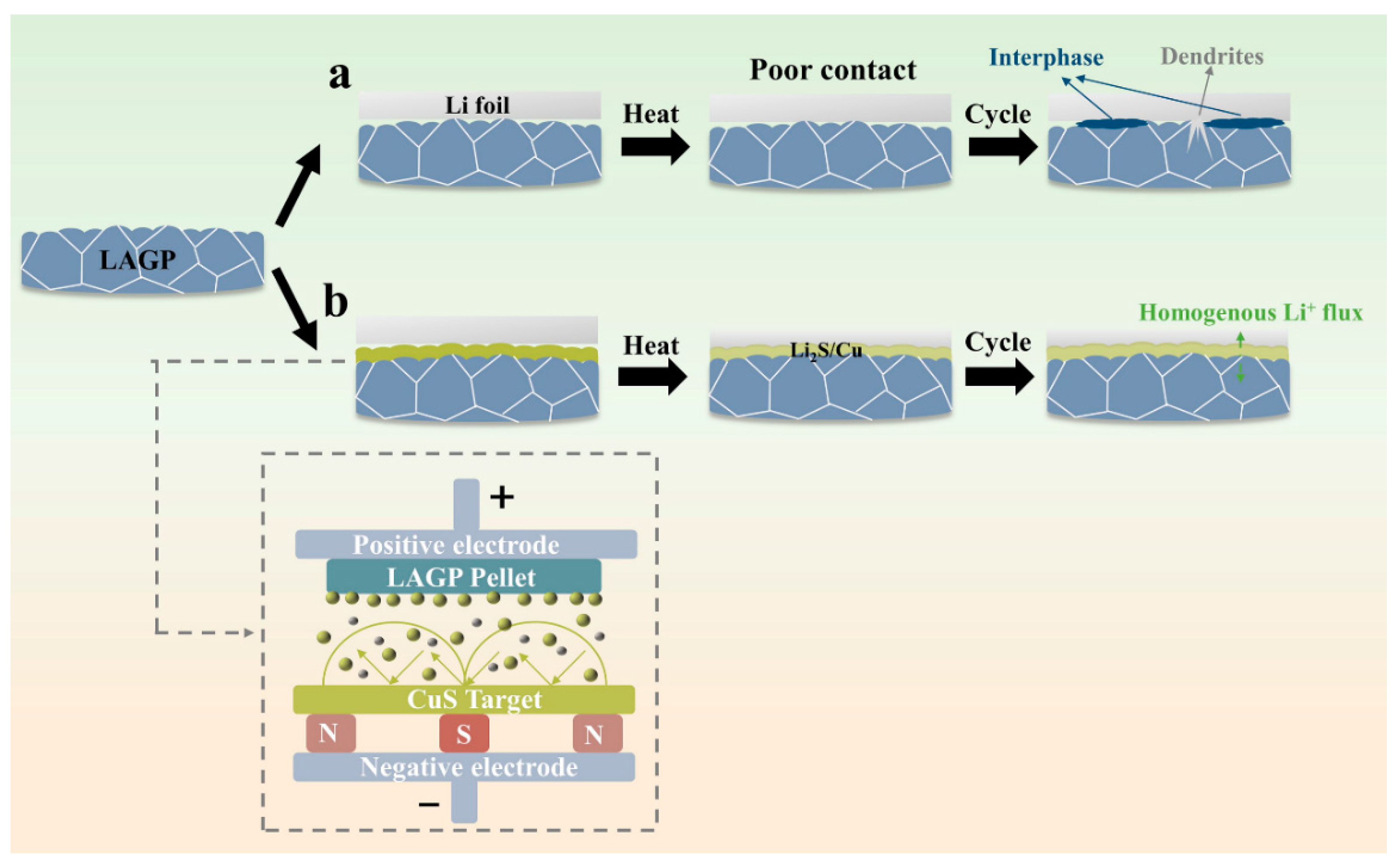
Figure 1. Schematics of symmetric cells’ structure with the Li anode and (a) LAGP (b) Li2S/Cu-modified LAGP as the electrolyte.
Batteries 09 00194 g001
Figure 2. Top-view SEM images: (a) planar of the original LAGP pellet and inserted optical photograph and (b) CuS@LAGP pellet and inserted optical photograph. (c) Cross-sectional SEM images of the CuS@LAGP pellet and (d) its corresponding high-resolution mapping.
Batteries 09 00194 g002
Figure 3. XRD patterns of the (a) LAGP pellet and (b) CuS film deposited on the Si plate.
Batteries 09 00194 g003
Figure 4. (a) Nyquist plot of an LAGP pellet from 20 to 80 °C and (b) its corresponding Arrhenius plot. (c) Nyquist plot of a CuS-LAGP pellet from 20 to 80 °C and (d) its corresponding Arrhenius plot.
Batteries 09 00194 g004
Figure 5. The CCD of the (a) pristine LAGP and (b) modified Li2S/Cu@LAGP symmetric cells. (c) Cycling stability performance of pristine LAGP and modified Li2S/Cu@LAGP symmetric cells at 0.1 mA cm−2 and its iconic curves.
Batteries 09 00194 g005
Figure 6. (a) Nyquist plots of Li|Li2S/Cu@LAGP|Li and Li|LAGP|Li cells. (b) Nyquist plot of the Li|Li2S/Cu@LAGP|Li cell after cycling for 300 h.
Batteries 09 00194 g006
Figure 7. SEM images of the Li metal, which are disassembled from (a) Li|LAGP|Li and (b) Li|Li2S/Cu@LAGP|Li cells for 50 cycles at 0.1 mA cm−2. SEM patterns of the surface of LAGP pellets, which are disassembled from (c) Li|LAGP|Li and (d) Li|Li2S/Cu@LAGP|Li cells. XPS spectra of (e) S 2p and (f) Cu 2p at the surface of the Li2S/Cu@LAGP electrolyte.
Batteries 09 00194 g007
Figure 8. Electrochemical performances of full cells based on the Li anode and LFP cathode at a constant temperature of 25 °C. (a) Scheme of the Li|Li2S/Cu@LAGP|LFP full cell assembly. (b) Comparison of the cyclic stability of two types of full cells at 0.1 C. Charge–discharge curves at the 1st, 5th, 20th, 50th, and 100th cycles at 0.1 C for (c) Li|LAGP|LFP and (d) Li|Li2S/Cu@LAGP|LFP cells. (e) Rate performances of two types of full cells.
Batteries 09 00194 g008
Figure 9. SEM images of LFP from (a) Li|Li2S/Cu@LAGP|Li and (b) Li|LAGP|Li cells after 23 cycles at 0.1 C. XPS spectra of Fe 2p for LFP disassembled from (c) Li|Li2S/Cu@LAGP|Li and (d) Li|LAGP|Li cells after 23 cycles.
Batteries 09 00194 g009
Figure 10. (a) Comparison of the cyclic stability of two types of full cells at 0.1 C without a liquid electrolyte. EIS plots of Li|Li2S/Cu@LAGP|LFP and Li|LAGP|LFP full cells (b) before and (c) after cycling for 23 cycles.
Batteries 09 00194 g010
Disclaimer/Publisher’s Note: The statements, opinions and data contained in all publications are solely those of the individual author(s) and contributor(s) and not of MDPI and/or the editor(s). MDPI and/or the editor(s) disclaim responsibility for any injury to people or property resulting from any ideas, methods, instructions or products referred to in the content.