Article

Topographical Optimization of a Battery Module Case That Equips an Electric Vehicle

1
Automotive Engineering and Transport Department, Technical University of Cluj-Napoca, 103–105 Muncii Avenue, 400114 Cluj-Napoca, Romania
2
PACS Faculty, Babes-Bolyai University of Cluj-Napoca, 71 General Traian Mosoiu St., 400347 Cluj-Napoca, Romania
*
Author to whom correspondence should be addressed.
Batteries 2023, 9(2), 77; https://doi.org/10.3390/batteries9020077
Submission received: 18 November 2022 / Revised: 9 January 2023 / Accepted: 19 January 2023 / Published: 23 January 2023

Abstract

:
The exponential development and successful application of systems-related technologies that can put electric vehicles on a level playing field in direct competition with vehicles powered by internal combustion engines mean that the foreseeable future of the automobile (at least) will be dominated by vehicles that have electric current stored in batteries as a source of energy. The problem at the European level related to the dependence on battery suppliers from Asia directly correlates with the need to use batteries as energy storage media for energy from renewable sources (photovoltaic and wind), and leads to the need for research into the possibilities for their reuse, remanufacturing or recycling (at the end of their life or purpose of use), and reintroduction, either fully or partially, back into the economy. This article presents possibilities for increasing the protection of the integrity of the cells that form a battery in the event of an impact/road accident, by the numerical analysis of a topographically optimized battery module case. The proposed solution/method is innovative and offers a cell protection efficiency of between 16.6–60% (19.7% to 40.7% if the mean values for all three impact velocities are considered). The efficiency of a cell’s protection decreases with the increase in impact velocity and provides the premise for a greater part of the saved cells to be reintegrated into other energy storage systems (photovoltaic and/or wind), avoiding future problems relating to environmental pollution.

1. Introduction

The potential of electric vehicles (EVs) as a suitable solution to the massive reduction in greenhouse gases caused by transportation is increasingly evident in the automotive industry, with numerous electric vehicles already on the market. Because, at this time, the field of transport mainly uses means of transport equipped with internal combustion engines, the pollution caused by them makes the field of transport one of the biggest contributors to greenhouse emissions and toxic emissions that affect the global population. The use of internal combustion engines powered by fossil fuels (diesel or petrol) leads to toxic emissions consisting of carbon dioxide (CO2), carbon monoxide (CO), nitrogen oxides (NOx), hydrocarbons (HC), and suspended particles (PM), volatile organic compounds (VOCs) [1,2], with a direct and negative impact on the environment and human health [3,4]. For example, in 2017, in Europe, road transport was responsible for almost 72% of total greenhouse gas emissions from transport, and of these emissions, 44% were from passenger cars, 9% from light commercial vehicles, and 19% came from heavy-duty vehicles [5].
For these main reasons, the development and use of electric vehicles directly and immediately contribute to the reduction in greenhouse gas pollution, as well as to the reduction in pollution in large urban agglomerations. Another aspect that should not be neglected is the operating/utilization costs of vehicles with conventional combustion engines and vehicles with an electric powertrain. It is estimated that it costs about six times less to operate an electric vehicle than an internal combustion engine vehicle, as the cost difference is primarily due to the low efficiency of internal combustion engines (30–35%) compared to the efficiency of electric motors (90–92%). The flow of cumulative mechanical and thermal losses leads to a decrease in the efficiency of the thermal engine by three times compared to an electric vehicle, and also, an electric vehicle consumes up to 75% of the energy for travel (motion), with the necessary energy stored in the batteries, which is about 6–10 km/kWh [6]. However, in addition to the primary advantages presented, there are two major barriers to massive entry into the automotive market for electric vehicles: the high cost of the energy source (25–45% of the purchase cost of an electric vehicle [6,7]) and the low storage capacity for electrical energy. A high battery energy capacity also brings higher costs, but at the same time increases the weight characteristics, which directly affects the autonomy of electric vehicles. For these reasons, there are currently several trends to increase the energy efficiency of electric vehicles by [7,8,9,10,11,12]:
  • The development of the energy capacity of cells through other technologies;
  • The functional optimization of the components of a battery cell;
  • High-performance and energy-efficient battery management systems (BMS);
  • The reduction of mechanical losses by reducing the number of components in the electric powertrain;
  • The development of energy flow management systems at the level of the entire vehicle;
  • The protection, safety, and security assurances in the use of energy sources.
Improving the safety of the energy sources used in electric vehicles requires major and constant attention from manufacturers [13,14]. Currently, there is much research that is focused on the safe integration of energy sources in electric vehicles to solve problems that can result in various safety incidents (which can lead to ignition and fire hazards), which are a pressing priority already in the design phase [13,15,16,17,18,19,20]. It is considered that the stresses that may appear in the exploitation of EV energy sources (Figure 1) are multiple from the point of view of physical phenomena.
In various research, the reactions to the safety incidents that occur in the energy sources after overloading have been analysed in detail, and based on this, the following classification, the external stresses on the energy sources have been determined as in [20,21,22] and as follows:
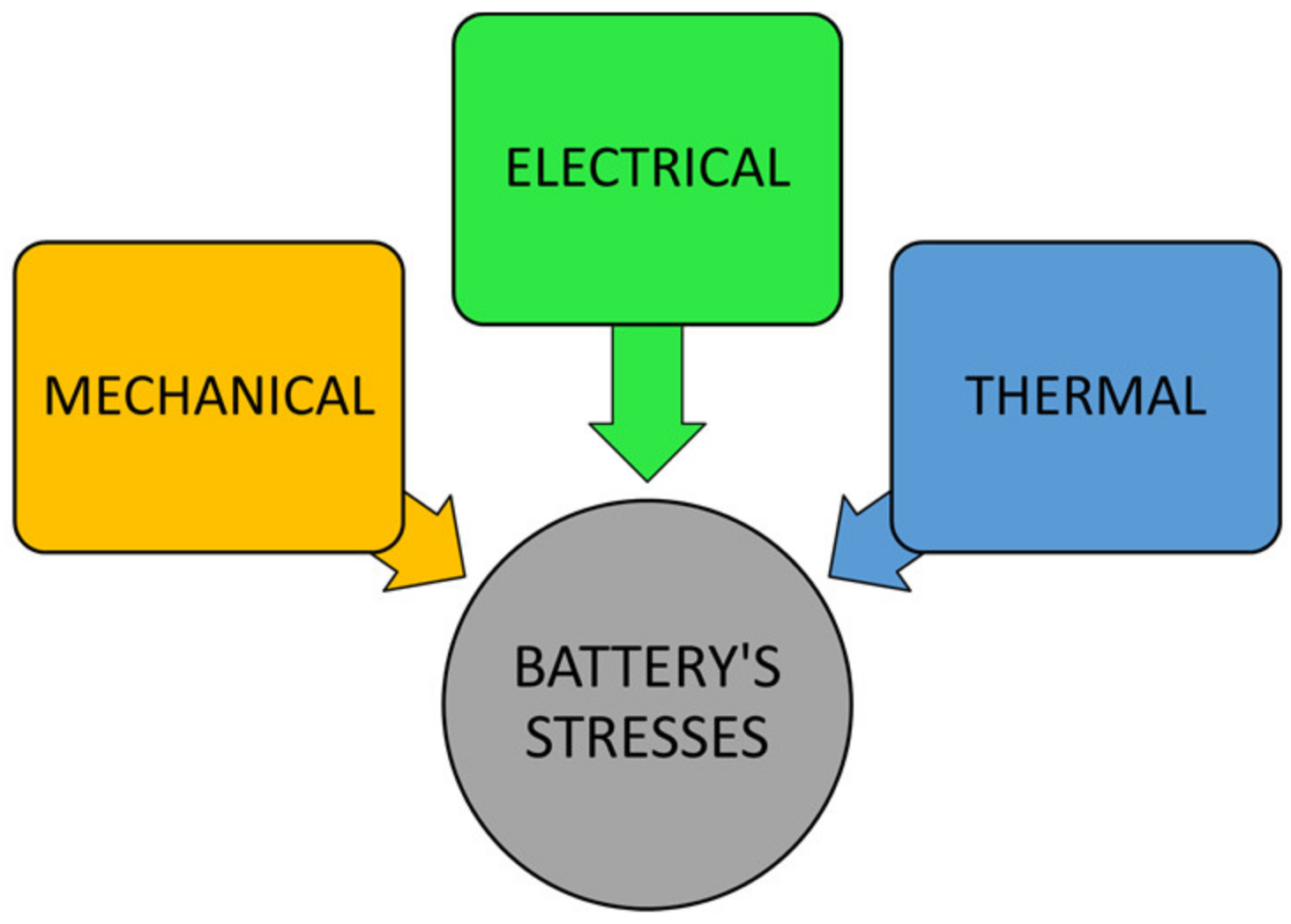
  • Mechanical: impact, deformation, penetration, free fall, mechanical shock, vibrations, and immersion.
  • Electrical: overload, overloading, forced download, and high C-rate.
  • Thermal: heating, overheating, and thermal runaway.
During the operation/exploitation of an electric vehicle, the battery may undergo deformations due to an external impact (as a result of a traffic accident), which subsequently leads to mechanical damage to the housing (case) and components of the battery systems. To improve the safety and performance of lithium-ion power sources, several international organizations and committees have promulgated standards and test specifications for power sources. These tests evaluate the safety limits of the energy sources, such as overload tests, mechanical deformation, and penetration tests, and the analysis of short-circuit and high-temperature behaviours [21,23]. The problem of the structural optimization of the battery case in electric vehicles has been addressed in various research, both at the micro level (the effect of mechanical impact on the cells) and at the macro level (the construction of the case and the materials used in construction). In most cases, modelling and numerical simulations were carried out, taking into account the immediate advantages offered by these engineering methods.
Recent research carried out by Ahn Y.J. et al. [24] and Muresanu and Dudescu [25] on safety issues in lithium-ion batteries in mechanical impact cases, used a numerical model to evaluate the degree of integrity of each component of the electric cell after being mechanical stressed. The numerical finite element models incorporating the multilayered structure showed good accuracy in the prediction of the cell-level failure mode, being verified through comparison with the experimental results.
Shui et al. proposed and applied a methodology to optimize the design of the battery case in four phases based on various optimization methods (central composite design—CCD, response surface methodology—RSM, artificial neural network—ANN, Latin hypercube sampling—LHS) [26]. Based on these methods, optimization of the structural rigidity was achieved by determining (reducing against an arbitrarily preset initial value) the optimal thickness of the plates (flats) that form the battery box. The material chosen for the construction of the battery case was aluminium and the battery cells considered were 18650-type Li-ion. It should be mentioned that the use of flat plates in the construction of the battery case can lead to an increased weight compared to construction with thinner plates and stiffening ribs.
Optimizing the construction and mechanical strength of the battery case from the point of view of using different materials (e.g., glass fibre composite, carbon fibre composite, and steel) were considered and researched by An Y. et al. [27]. The study was carried out using numerical simulation methods and showed that the use of carbon fibre composite in the construction of the battery case offers advantages in high strength and low weight. A 30% deformation of the casing was achieved at a force of 81 kN using steel compared to a force of 100 kN for carbon fibre composite.
Ruan et al. [28] also used numerical simulation methods to address the constructive optimization problem of the lug connection and the upper cover of a battery case. They considered that the structural stresses were due to acceleration loads in all directions on the battery, and the major conclusion was that the maximum stress occurred in the connection area between the battery pack ears and the box (of 86 mm, for the particular construction of the battery considered in the study). It should be mentioned that in this study, a specific box construction and geometric shape were used, and the plates that formed the box were considered flat and without stiffness ribs.
Qiao et al. added additional EVA (Ethylene-vinyl acetate) foam in the construction of the battery to try and identify the effect on the integrity of the battery in the case of an accident (frontal collision at 50 km/h with a wall) [29]. Based on the imposed conditions and restrictions, they obtained a reduction in deformation of 8.2% for the area of the electrochemical cells and a reduction of 12.65% for the maximum deformation of the casing (by adding EVA foam). However, the study had many limitations: the construction of the battery case and the monomer model were simple, the design, heat dissipation structure, and the external connection of the battery case were not taken into account, and the frontal impact was made with a fixed wall that did not faithfully represent the construction of the body of a vehicle. The plates from which the battery case were made were also flat (without stiffening ribs).
The research carried out by Pan Y. et al. [30] focused on the possibility of reducing the weight of the battery case while maintaining the mechanical resistance properties. The type of material and its optimal thickness were determined using different optimization methods, considering fixed-frequency vibration, and mechanical shock and fatigue life analysis. Further, the obtained optimized design of the battery pack was tested in different tests (crush and crash simulations), which considered the impact of the battery case with a cylindrical pilar (a particular situation that cannot happen because of the design of the car body structure). Regardless, the results obtained showed that the impact protection of the battery was maintained, along with a weight reduction of 10.41% (by changing the construction material of the battery case).
Dong S. et al. [31] addressed the optimization of battery case construction by considering a multitude of goals: to improve the protection level of the battery pack to IP68; to reduce the weight of the battery box frame structure; to simplify the cooling mode of the battery pack; and to improve the battery protection level. In general, the research focused on optimizing the internal resistance structure of the battery (which allowed for the assembly of the modules that made up the battery), and flat plates and covers that made up the battery case (they were not considered in the optimization process). The results obtained showed that it was possible to maintain the mechanical resistance of the battery case by applying a new design and achieved thermal management through a natural air-cooling scheme, which led to a reduction in the total weight of the energy source by 450 kg.
The use of a sandwich-type structure (based on an innovative auxetic structure, located in the core of the structure) to protect the battery system of an electric vehicle in the case of an impact of the load with the road, was designed and studied by Biharta M.A.S. et al. [32]. The protection efficiency of this composite structure was analysed using the nonlinear finite element method and showed that under certain impact conditions, the battery cells were very well protected (a maximum deformation of 1.92 mm was obtained, below the deformation threshold that causes failure of the cells/battery). Another study on the use of sandwich structures in the construction of battery cases was carried out by Pratama L.K. et al. [33]. An optimized form of the lattice structure was determined by considering the structure that offered the highest impact energy absorption value, which was then used further to analyse the protection of a battery in an impact with a body (impactor) at a speed of 42 m/s. Under the conditions imposed on the simulation, the maximum measured deformation of the battery was 2.7 mm, which demonstrated the effectiveness of the construction.
It must be emphasized that with the increasing use of EVs in traffic, there will inevitably be accidents that affect the structural integrity of the batteries, which highlights the need for a specific and effective recycling process. In this context, at the level of the European Union, steps have been taken to establish future directions and policies regarding the need to adopt measures to reintegrate batteries that are no longer used in vehicles into other energy storage systems, or in other industrial processes. In the European Commission document “Green Deal: Sustainable batteries for a circular and climate neutral economy” (2020), it is specified that batteries introduced to the EU market (including those used in the construction of electric vehicles) must be durable, effective, and safe throughout their life cycle [34]. Batteries must be manufactured with the lowest possible environmental impact, using materials obtained with full respect for human rights, as well as social and ecological standards. Batteries must be long-lasting and safe, and at the end of their useful life or purpose, they must be reused, remanufactured, or recycled, putting all or part of them back into the economy. It is expressly stated that “…the reuse of batteries from electric vehicles will be facilitated, so that they can have a second life, for example as stationary energy storage systems, or their integration into electrical networks as energy resources”.
Under the conditions and premises presented previously, the topic of this article falls into a topical area of major interest (both on a European and international level) regarding the identification of solutions to increase the degree of inclusion of batteries equipping electric vehicles in the circular economy (reuse of batteries) [35], by optimizing the battery module case to protect against structural mechanical stresses and to protect the electrochemical cells against impact/road accidents. Furthermore, from the analysis of the most recent studies relating to the constructive optimization of the battery case for the protection of the cells upon impact (and already briefly presented), the idea proposed in this article is new. The restriction used for the topographical optimization of the battery casing (box) covers increases the rigidity of the casing through the construction of special ribs. The use of optimized battery case covers provided with stiffening ribs leads to the possibility of using thinner plates (in this case, aluminium), and implicitly, the reduction in the total weight of the battery case (while maintaining the mechanical rigidity properties).

2. Materials and Methods

The research carried out on the possibilities of increasing the integrity of the battery cells (which equip an electric vehicle) to protect against the event of a road accident (through the constructive topographic optimization of the casing) has been carried out in the following directions (see Figure 2):
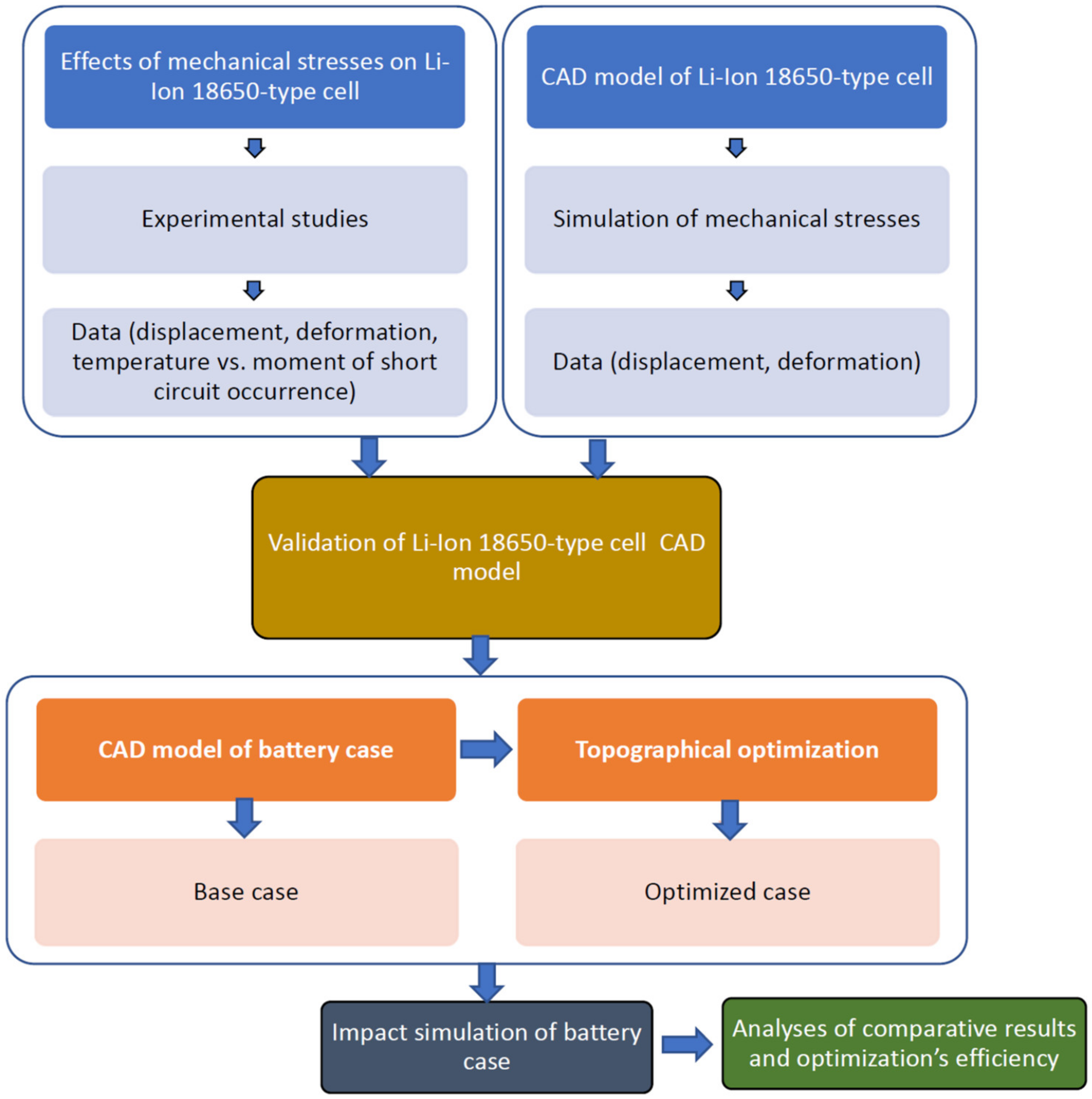
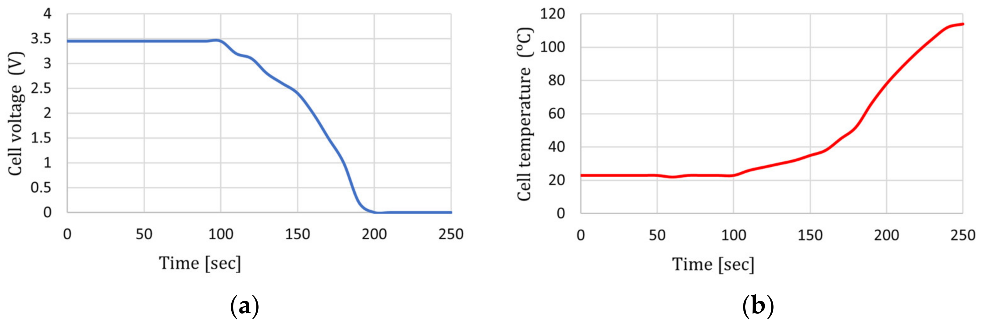
  • Experimental research—The first direction of research was an experimental one and aimed to identify the point where (following mechanical deformation stresses on a Samsung 18650-type cell, with an 80% state of charge) the short-circuit occurs, and the cell becomes unusable.
  • Numerical CAD modelling of a 18650-type cell—the creation of a CAD model considering the cell’s complex construction/design.
  • Validation of a 18650-type cell CAD model—using experimentally obtained data.
  • Numerical CAD modelling of a battery case—the creation of a CAD model for a battery (including the internal thermal management system), consisting of 12 modules (a total number of 5760 cells, where each module is made of 480 cells).
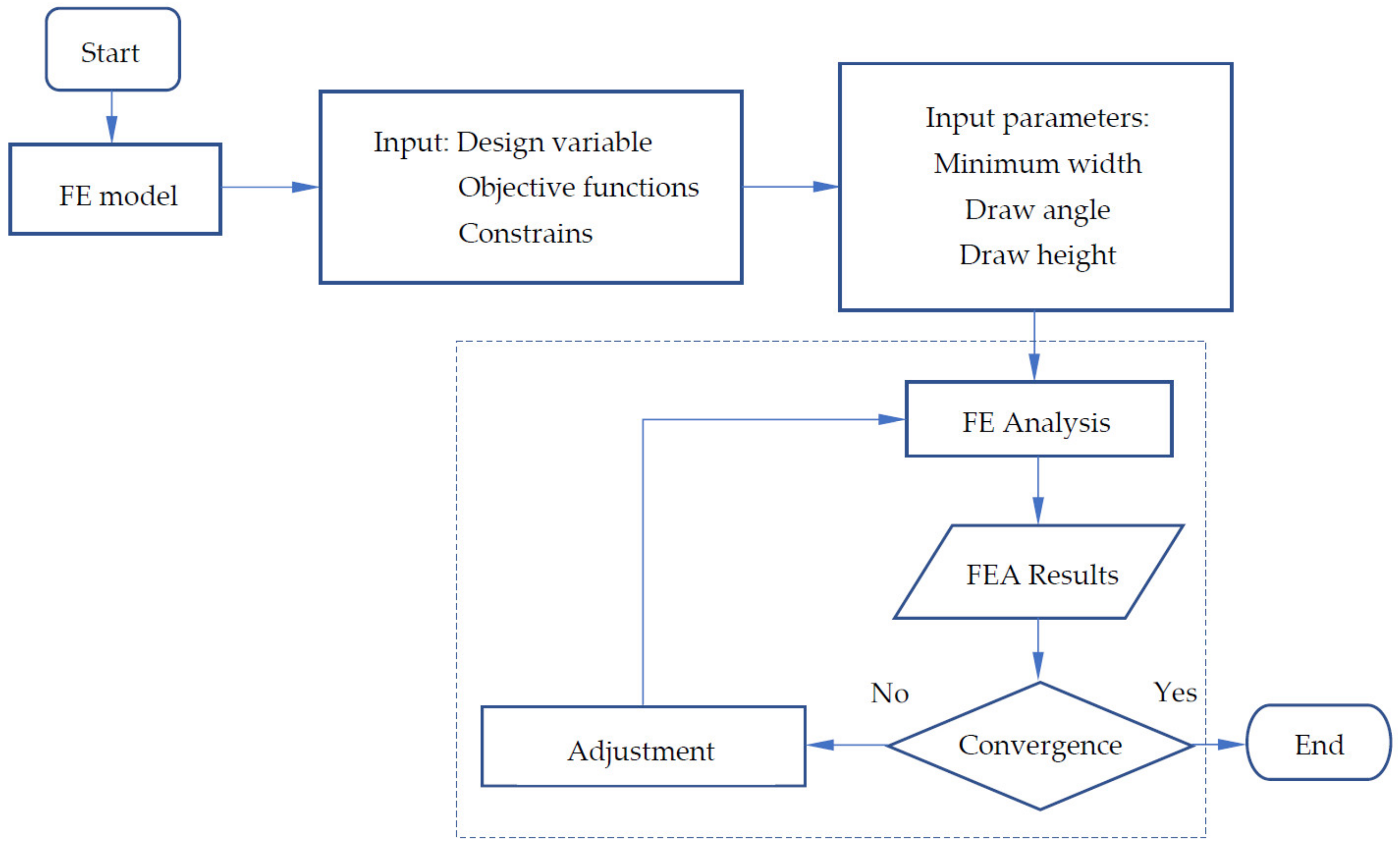
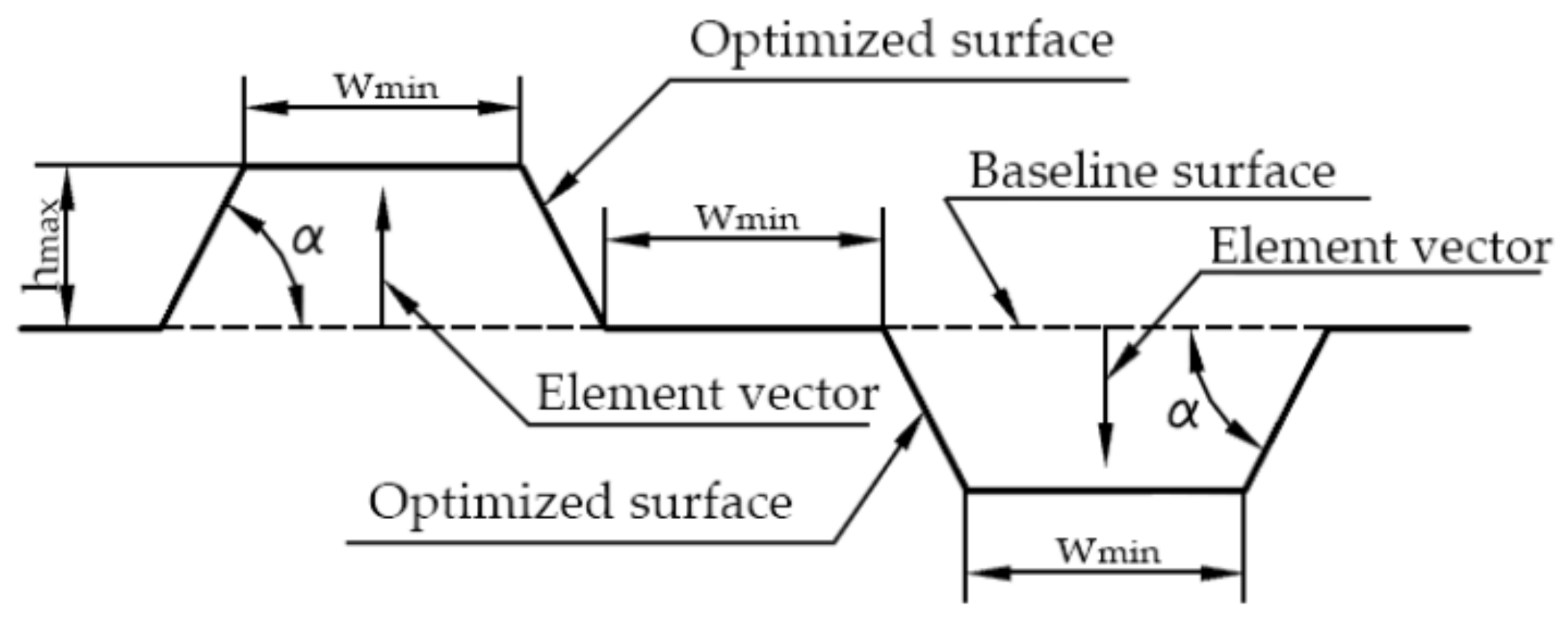
  • Topographical optimization—the idea of a topographical optimization of the upper and lower surface of the battery case was approached by imposing a restriction relating to the real-world conditions of an electric vehicle. The considered restriction was the range of frequencies (vibrations) due to the tire–road interaction, which are transmitted to the vehicle chassis (and implicitly to the mechanical structure of the battery).
  • Numerical simulation of base and optimized cases.
  • Comparative analysis of data and conclusions on the efficiency.

2.1. Experimental Research

The experimental tests were performed in a closed room with an average ambient temperature of 20 °C, using an experimental stand and 50 experimental tests (on 50 cells). The experimental stand was configured using a 10-ton hydraulic press, a mini hydraulic group equipped with an electric motor, and the associated hydraulic installation equipment (Figure 3). The hydraulic group was equipped with a simple manual valve that allowed the oil flow to be adjusted between 0.52 and 2.5 L/min, at a working pressure between 50–600 bar. The terminals of the voltmeter were placed at the two terminals of the cell (to identify the moment of short-circuit) and the temperature measuring probe was placed on the cell anode area. Figure 3 shows the configuration of the cylindrical cell bending test system. The linear movement of the piston is driven by the hydraulic pump with an advance of 5 mm/minute and the T-type device bends and deforms the test cell. The obtained results were analysed and validated with statistical tests (removal of erroneous values using Fischer’s test). The corresponding values from the 50 tests were averaged and are shown in Figure 4 and Figure 5.
Under the action of the deformation force, the cell’s functional parameters started to change at the 100th second. The cell voltage changed from 3.45 V to 3.20 V at a deformation of 4 mm and reached lower than 3 V at the 130th second at a cell deformation of 6.4 mm.
The short-circuit that occurred at the 190th second was also highlighted by the sudden variation in the battery temperature, with an immediate increase from 25 °C to a maximum value of 114 °C (roughly a 5-fold increase). The value of the force at the onset of the short-circuit was 7.18 kN at a cell deformation of 9.8 mm.

2.2. Numerical Modelling and Simulation

2.2.1. Numerical Modelling and Simulation of the 18650-Type Cell

The CAD model of the cylindrical cells was created using SolidWorks computer-aided design software. The geometric dimensions used to create the models corresponded to the real physical dimensions of the cells used in the experimental tests and the cell geometry was imported into HyperMesh and prepared for discretization into finite elements. For each part of the cell, an optimal quality criterion was applied. After the generation of the finite element model, the mechanical structural properties and the materials were assigned, and the last step of this stage was the definition of the load case (forces, contact between components, and impact body velocity). TYPE7 was used as the contact interface, which ensures permanent contact between the model’s surfaces. The properties of the materials used are centralized in Table 1 (the material type assigned to the components being M2_PLAS_JOHNS_ZERIL). This is an isotropic elastic–plastic type of material and reproduces internal stresses as a function of strain, strength, and temperature. All components of this study were meshed into mixed shell elements, having assigned type P1_SHELL predefined properties. The preprocessing part was carried out in Altair HyperMesh software in the Radioss solver environment. The results obtained from the simulation process were interpreted using the HyperView and HyperGraph modules of HyperWorks software.
From the simulation results, when analysing the distribution of von Mises stresses (Figure 6a), the maximum value appeared in the outer areas of the battery case where the impactor has the main point of impact (6.245 × 10⁻¹ GPa).
In the graph presented in Figure 7, the results from the experimental tests and the results from the simulation for the bending of the 18650-type cell were superimposed. The analysis of the results shows that the force–deformation variation is almost linear and the experimental results curve follows the simulation results curve through almost the entire deformation range considered. It was also considered that the CAD model of the cell was validated and could be used further in the study since the differences between the simulated and experimental values were approximately 1% (A maximum of 13% difference was recorded for the very final part, which was outside of the range of consideration in this study).

2.2.2. Topographical Optimization of the Battery Module Case

The batteries that equip electric vehicles must have a certain mechanical rigidity required for the manufacturing process, the handling process, and actual use. Hence, at present, it was found that the necessary rigidity of the battery case is achieved by creating ribs on the surface/surfaces of the case (especially the upper and lower surfaces), ribs whose shapes and placement differ from one manufacturer to another. In general, topographic optimization is applied to flat or already deformed surfaces of a model to reach a geometric shape with reinforcements on various surfaces, so that, through this process, a product can be developed to meet the constructive parameters and ensure a higher level of functionality. Optimization can be performed on the components of an assembly or subassembly, wherever it is considered that there is potential for improvement. In the process of topographical optimization of a basic model, certain configuration levels must be completed in the optimization algorithm: design and development of the model; defining the variables for topographical optimization; defining optimization responses; and postprocessing and analysis of the results. In carrying out this study, we started with a battery module case based on a simple geometric model, with well-defined flat surfaces and with the following geometric dimensions: a length of 500 mm, a width of 240 mm, and a height of 73 mm (Figure 8). The optimization areas chosen were the lower and upper surfaces of the battery module case. The material chosen and defined for the module case model was aluminium, due to its low specific weight, thus reducing the total weight of the battery assembly (thickness, 4 mm; density, 2.7 g/cm3; Poisson’s ratio, 0.33; and Young’s modulus, 70 GPa).
Topographic optimization is an advanced shape optimization, applicable to models discretized into shell elements, and the process is presented in Figure 9. The process of topographic optimization begins by creating the finite element model from the imported basic geometry of the model. The definition of objective functions, design variables, and the creation of the load case is carried out in the second part of the process. The required design parameters are represented by the minimum width of the geometric elements (wmin = 28 mm), the height of the elements (hmax = 2 mm), and the drawing angle (α = 82°) (Figure 10).
After creating the load case, the model was statically analysed to extract the vibration modes in the frequency range of 22–33 Hz (a frequency range generally considered to be transmitted to the vehicle chassis due to the wheel–road interaction and also to the battery and the battery case, which is fixed to the chassis [37]). In the last stage of the process, it was determined if the results converged towards a feasible solution. If the results converged, then the optimization process was completed by generating the optimized model of the battery case, and in a case where the results did not converge, the process would enter an iterative loop by modifying the geometrics of the beads and reanalysing the pattern until its geometry converged.
After the optimization process was performed on the base case, the topographic optimization algorithm provided an optimized model according to the input data (Figure 11). Furthermore, the optimized model was completed by the geometric optimization of the areas proposed by the algorithm, for the construction of simple geometric shapes (which are easy to implement in the manufacturing process).
To continue the comparative analysis between the basic case model and the optimized version, an electric vehicle battery pack including 12 modules was modelled, each module having 480 electrochemical cells (18650-type), resulting in a total number of 5760 cells (Figure 8). The discretization was performed in 767,396 shell elements for the basic model (initial shell) and 869,620 shell elements for the topographically optimized shell.
It should also be noted that these simulations did not consider the thermal influences that may occur (temperature variations in the external environment and variations due to the electrochemical processes in operation), and a constant temperature of 25 °C was considered (it was considered that the battery has a functional thermal management system).
The numerical analysis aimed to analyse the behaviour and the mechanical deformation of the cells and the battery module in the event of impact/accident (the effect of impact on the integrity of the battery’s cells).
The most unfavourable case was also chosen in terms of the possibility of accidental damage to the battery, namely the side impact to the body of an electric vehicle (the impact area is located between the vehicle’s pillars A and B), and the hypothesis considered was that only a maximum of 80% of the total impact force/energy was transmitted to the battery pack (Figure 12). In the case of a frontal impact, the design of the vehicle chassis offers the greater possibility of absorbing and dispersing a large part of the impact energy up to the area where the battery is located; in the case of a side impact, the battery is essentially only protected by the longitudinal beams, the passenger compartment floor, and the structures that form the body (pillars).
Reporting on the efficiency of the topographical optimization solution for the battery, a scenario was chosen that represented the number of cells that undergo deformation, but which, according to the experimental research carried out, remains in a working condition (a short-circuit does not occur) and can be reused. The chosen value of the maximum deformation that could be suffered by a cell, at which the cell is still considered to be functional, is 2.5 mm (measured on the transversal plane of the cell, i.e., 15% of the size of the diameter of the 18650-type cell). The test impact velocities considered for both the initial/base and topographically optimized cases were 36 km/h (10 m/s), 72 km/h (20 m/s), and 108 km/h (30 m/s).

3. Results and Discussion

The obtained results for the simulation of the deformation of the battery modules (and the effects on the integrity of the cells) under the considered impact conditions are presented below, considering the variation in the mechanical stresses, kinetic energy and internal energy, and von Mises stress values. The energy balance plots represent the method to check the quality of the results. An important indicator for proper analysis is the total energy of the system, which remains constant. It can be observed that the total energy variation remains almost constant in all simulation cases and the higher values of the kinetic energy are absorbed in the frame and the case structure. To obtain an accurate simulation result, more attention was focused on hourglass energy, which must be less than 5% of the overall internal energy.
The results obtained by simulating the battery module case are presented in Figure 13, Figure 14, Figure 15, Figure 16, Figure 17, Figure 18, Figure 19, Figure 20, Figure 21, Figure 22, Figure 23, Figure 24, Figure 25, Figure 26, Figure 27, Figure 28, Figure 29 and Figure 30, both for the basic version and for the topographically optimized version (considering parameters such as: energy balance, displacement and von Mises stresses). For a better view of the deformation and mechanical stresses that occur in the battery cells area, the module cover is hidden.
The energy balance was plotted after the impact analysis of the battery modules. The kinetic energy variation shown in Figure 13 starts at an initial value of 47,773.4 J and remains constant until the first 1.7 ms when the battery assembly first comes into contact with the longitudinal beam. Thereafter, the kinetic energy drops dramatically, intersecting the internal energy variation at 24,080 J, and continues to decrease to near zero at 8 ms. During the impact, the first row of cells in the battery of the first module is initially damaged by direct contact with the case, while the following rows of cells absorb (and at the same time dissipate) the mechanical shock through contact with the first row of batteries. The deformation of the battery cells due to the impact at a velocity of 10 m/s is shown in Figure 15, where the first row of batteries located in the impact area is partially damaged and the heat exchanger is destroyed during the impact.
The energy balance variation during the rigid side impact of the optimized battery assembly model is presented in Figure 16. The maximum kinetic energy curve starts from the same kinetic energy value as the previous simulation for the base model. The kinetic energy curve intersects the internal energy curve at 23,966.84 J, at 3.185 ms. In Figure 18 it can be observed that the largest deformations are in the impact area of the first rows of battery cells of the battery’s modules. The cells are not seriously damaged, compared to the simulation results of the base module simulation. Increasing the impact velocity of the battery packs, the number of damaged batteries is higher, as can be viewed in Figure 20, Figure 23, Figure 26 and Figure 29. In addition to the previous basic simulation, the more affected cells are situated in the impact area and on the opposite side of the battery module frame. The deformation from the opposite of the impact area is due to the mass attached to the battery module’s support. In the simulation case presented for optimized module, the number of affected cells is lower than in the previous basic simulation case.
Following the simulations carried out in the three cases with different impact velocities and with different case models (base vs. topographically optimized), a series of values were obtained for the number of batteries deformed by less than 2.5 mm (maximum value at which the cells are considered/alleged to be (still) electrically functional), as shown in Table 2.
Based on the results obtained, it can be stated that the proposed constructive solution offers a reduction in cell deformation with an efficiency of between 16.6–60% (19.7% to 40.7% if the mean value differences are considered for all three impact velocities), which shows that the topographically optimized solution (from a constructive point of view) presents more effective battery case protection against the mechanical stresses from impact phenomena (i.e., road accidents). It should be noted that through topographical optimization, the case tends to be more effective in protecting the cells of the battery, but at the same time, the modification of the optimized surfaces (by increasing them) also leads to modification of the mass of the battery case covers. A larger mass has an immediate effect in the possibility of taking over (and dispersing) more of the impact energy, maintaining the deformation of the structure in the plastic domain for a longer period of time.
Considering that, according to the statistics on road accidents in the EU, most accidents take place at low velocity, it can be observed that for the proposed constructive battery case solution, the maximum effect is obtained at low impact velocities (<36 km/h), and at an impact velocity greater than 70 km/h the difference falls below 17%. Thus, the effectiveness of the mechanical protection for the battery cells through the proposed method of topographical optimization could provide a benefit in the application of the circular economy concept by reusing more valid electrochemical cells in other/future constructions of energy sources, reducing (or why not eliminating) costs and economic and environmental pollution due to industrial manufacturing processes.

4. Conclusions

Based on the results obtained from the experimental research activities and numerical analysis presented in this article, it can be stated that research in the field of electric vehicles is necessary, current, and important, considering the continuous growth dynamics of the number of electric vehicles in traffic, with the immediate reality that they will inevitably be involved in road accidents. Considering the major cost that an energy source (battery) is as part of the total construction costs of an electric vehicle, as well as the risks associated with electrochemical cells’ behaviour in the event of accidents, this article presents an approach that aims to improve the construction of the energy source protective housing/case for electric vehicles from the design phase to impact, to meet the requirements related to their use and operation in conditions of maximum safety and reliability.
The structural optimization of the battery module case was based on the topographical optimization process (considering the vibrations due to the wheel–road interaction transmitted to the chassis), which allowed for the proposal of a modified but rigid casing structure. In the study, the most unfavourable case of a road accident was considered, namely the side impact (impact area between A and B pillars, for different impact velocities), and the proposed theme was studied through numerical analysis methods (modelling and simulation). Based on the obtained results, it was observed that there was a reduction in the number of damaged cells, which shows that the proposed topographically optimized solution tends to be highly effective at low impact velocities (<36 km/h), when a major number of batteries are protected from impact (with 27.8% more protection). The functional remaining cells can later be used in other constructions/applications of energy sources that do not require strict and highly efficient operating parameters, according to the circular economy concept.
The main directions for future research and development that can offer solutions for the reuse of electrochemical cells in the construction of electric vehicle batteries could be the use of other/complex topographical restrictions to further optimize the design of the casing shape, topographical optimization of all casing surfaces, the development and use of a complex numerical model of an electrochemical cell that also takes into account the mechanics of the internal chemical structure of the battery (friction phenomena for example), and the influences of the electrochemical and thermal phenomena that occur in the operation of the battery.

Author Contributions

Conceptualization, I.S. and F.M.; methodology, I.S. and F.M.; validation, I.S. and L.I.S.; formal analysis, I.S., L.I.S., and H.R.; investigation, I.S.; data analysis and curation, H.R.; writing—original draft preparation, F.M. and H.R.; writing—review and editing, F.M. and H.R.; supervision, F.M. All authors have read and agreed to the published version of the manuscript.

Funding

This research received no external funding.

Data Availability Statement

Not applicable.

Acknowledgments

The authors express their gratitude to the Technical University of Cluj-Napoca, for the financial support in the publication of this article.

Conflicts of Interest

The authors declare no conflict of interest.

References

  1. Winkler, S.L.; Anderson, J.E.; Garza, L.; Ruona, W.C.; Vogt, R.; Wallington, T.J. Vehicle criteria pollutant (PM, NOx, CO, HCs) emissions: How low should we go? Clim. Atmos. Sci. 2018, 1, 26. [Google Scholar] [CrossRef] [Green Version]
  2. Abdel-Rahman, A.A. On the emissions from internal-combustion engines: A review. Int. J. Energy Res. 1998, 22, 489–513. [Google Scholar] [CrossRef]
  3. Adeyanju, A. Effects of Vehicular Emissions on Human Health. J. Clean Energy Technol. 2018, 6, 411–420. [Google Scholar] [CrossRef] [Green Version]
  4. Kim, B.-G.; Lee, P.-H.; Lee, S.-H.; Kim, Y.-E.; Shin, M.-Y.; Kang, Y.; Bae, S.-H.; Kim, M.-J.; Rhim, T.; Park, C.-S.; et al. Long-Term Effects of Diesel Exhaust Particles on Airway Inflammation and Remodeling in a Mouse Model. Allergy Asthma Immunol. Res. 2016, 8, 246–256. [Google Scholar] [CrossRef] [Green Version]
  5. European Environmental Agency (EEA). Greenhouse Gas Emissions from Transport in Europe. 2020. Available online: https://www.eea.europa.eu/data-and-maps/indicators/transport-emissions-of-greenhouse-gases/transport-emissions-of-greenhouse-gases-12 (accessed on 15 September 2022).
  6. Chau, K.T.; Chan, C.C. Emerging Energy-Efficient Technologies for Hybrid Electric Vehicles. Proc. IEEE 2007, 95, 821–835. [Google Scholar] [CrossRef]
  7. Amamra, S.-A.; Tripathy, Y.; Barai, A.; Moore, A.D.; Marco, J. Electric Vehicle Battery Performance Investigation Based on Real World Current Harmonics. Energies 2020, 13, 489. [Google Scholar] [CrossRef] [Green Version]
  8. Kim, J.-S.; Lee, D.-C.; Lee, J.-J.; Kim, C.-W. Optimization for maximum specific energy density of a lithium-ion battery using progressive quadratic response surface method and design of experiments. Sci. Rep. 2020, 10, 15586. [Google Scholar] [CrossRef] [PubMed]
  9. Lei, Y.; Zhang, C.; Gao, Y.; Li, T. Charging Optimization of Lithium-ion Batteries Based on Capacity Degradation Speed and Energy Loss. Energy Procedia 2018, 152, 544–549. [Google Scholar] [CrossRef]
  10. Li, R.; Wei, X.; Sun, H.; Sun, H.; Zhang, X. Fast Charging Optimization for Lithium-Ion Batteries Based on Improved Electro-Thermal Coupling Model. Energies 2022, 15, 7038. [Google Scholar] [CrossRef]
  11. Liu, K.; Kang Li, K.; Peng, Q.; Zhang, C. A brief review on key technologies in the battery management system of electric vehicles. Front. Mech. Eng. 2019, 14, 47–64. [Google Scholar] [CrossRef]
  12. Buidin, T.I.C.; Mariasiu, F. Battery Thermal Management Systems: Current Status and Design Approach of Cooling Technologies. Energies 2021, 14, 4879. [Google Scholar] [CrossRef]
  13. Lai, W.-J.; Ali, M.Y.; Pan, J. Mechanical behavior of representative volume elements of lithium-ion battery modules under various loading conditions. J. Power Source 2014, 248, 789–808. [Google Scholar] [CrossRef]
  14. Abada, S.; Marlair, G.; Lecocq, A.; Petit, M.; Sauvant-Moynot, V.; Huet, F. Safety focused modeling of lithium-ion batteries: A review. J. Power Source 2016, 306, 178–192. [Google Scholar] [CrossRef]
  15. Feng, X.; Ouyang, M.; Liu, X.; Lua, L.; Xia, Y.; He, X. Thermal runaway mechanism of lithium ion battery for electric vehicles: A review. Energy Storage Mater. 2018, 10, 246–267. [Google Scholar] [CrossRef]
  16. Gao, Z.; Zhang, X.; Xiao, Y.; Gao, H.; Wang, H.; Piao, C. Influence of Low-Temperature Charge on the Mechanical Integrity Behavior of 18650 Lithium-Ion Battery Cells Subject to Lateral Compression. Energies 2019, 12, 797. [Google Scholar] [CrossRef] [Green Version]
  17. Sahraei, E.; Meier, J.; Wierzbicki, T. Characterizing and modeling mechanical properties and onset of short circuit for three types of lithium-ion pouch cells. J. Power Source 2014, 247, 503–516. [Google Scholar] [CrossRef]
  18. Zhu, J.; Zhang, X.; Sahraei, E.; Wierzbicki, T. Deformation and failure mechanisms of 18650 battery cells under axial compression. J. Power Source 2016, 336, 332–340. [Google Scholar] [CrossRef]
  19. Xu, J.; Ma, J.; Zhao, X.; Chen, H.; Xu, B.; Wu, X. Detection Technology for Battery Safety in Electric Vehicles: A Review. Energies 2020, 13, 4636. [Google Scholar] [CrossRef]
  20. Evarts, E.C. Lithium batteries: To the limits of lithium. Nature 2015, 526, 93–95. [Google Scholar] [CrossRef] [Green Version]
  21. Chombo, P.V.; Laoonual, Y. A review of safety strategies of a Li-ion battery. J. Power Source 2020, 478, 228649. [Google Scholar] [CrossRef]
  22. Klink, J.; Hebenbrock, A.; Grabow, J.; Orazov, N.; Nylén, U.; Benger, R.; Beck, H.-P. Comparison of Model-Based and Sensor-Based Detection of Thermal Runaway in Li-Ion Battery Modules for Automotive Application. Batteries 2022, 8, 34. [Google Scholar] [CrossRef]
  23. Ruiz, V.; Pfrang, A.; Kriston, A.; Omar, N.; Van den Bossche, P.; Boon-Brett, L. A review of international abuse testing standards and regulations for lithium ion batteries in electric and hybrid electric vehicles. Renew. Sustain. Energy Rev. 2018, 81, 1427–1452. [Google Scholar] [CrossRef]
  24. Ahn, Y.J.; Lee, Y.-S.; Cho, J.-R. Multi-Layered Numerical Model Development of a Standard Cylindrical Lithium-Ion Battery for the Impact Test. Energies 2022, 15, 2509. [Google Scholar] [CrossRef]
  25. Muresanu, A.D.; Dudescu, M.C. Numerical and Experimental Evaluation of a Battery Cell under Impact Load. Batteries 2022, 8, 48. [Google Scholar] [CrossRef]
  26. Shui, L.; Chen, F.; Garg, A.; Peng, X.; Bao, N.; Zhang, J. Design optimization of battery pack enclosure for electric vehicle. Struct. Multidiscip. Optim. 2018, 58, 331–347. [Google Scholar] [CrossRef]
  27. An, Y.; Wang, X.; Dou, N.; Wu, Z. Strength analysis of the lightweight-designed power battery boxes in electric vehicle. E3S Web Conf. 2022, 341, 01025. [Google Scholar] [CrossRef]
  28. Ruan, G.; Yu, C.; Hu, X.; Hua, J. Simulation and optimization of a new energy vehicle power battery pack structure. J. Theor. Appl. Mech. 2021, 59, 565–578. [Google Scholar] [CrossRef]
  29. Qiao, W.; Yu, L.; Zhang, Z.; Pan, T. Study on the Battery Safety in Frontal Collision of Electric Vehicle. J. Phys.: Conf. Ser. 2021, 2137, 012008. [Google Scholar] [CrossRef]
  30. Pan, Y.; Xiong, Y.; Wu, L.; Diao, K.; Guoa, W. Lightwieght design of an automotive battery-pack enclosure via advanced high-strength steels and size optimization. Int. J. Automot. Technol. 2021, 22, 1279–1290. [Google Scholar] [CrossRef]
  31. Dong, S.; Lv, J.; Wang, K.; Li, W.; Tian, Y. Design and Optimization for a New Locomotive Power Battery Box. Sustainability 2022, 14, 12810. [Google Scholar] [CrossRef]
  32. Biharta, M.A.S.; Santosa, S.P.; Widagdo, D.; Gunawan, L. Design and Optimization of Lightweight Lithium-Ion Battery Protector with 3D Auxetic Meta Structures. World Electr. Veh. J. 2022, 13, 118. [Google Scholar] [CrossRef]
  33. Pratama, L.K.; Santosa, S.P.; Dirgantara, T.; Widagdo, D. Design and Numerical Analysis of Electric Vehicle Li-Ion Battery Protections Using Lattice Structure Undergoing Ground Impact. World Electr. Veh. J. 2022, 13, 10. [Google Scholar] [CrossRef]
  34. European Commission. Green Deal: Sustainable Batteries for a Circular and Climate Neutral Economy. 2020. Available online: https://digital-strategy.ec.europa.eu/fr/node/475/printable/pdf (accessed on 15 September 2022).
  35. Kehl, D.; Jennert, T.; Lienesch, F.; Kurrat, M. Electrical Characterization of Li-Ion Battery Modules for Second-Life Applications. Batteries 2021, 7, 32. [Google Scholar] [CrossRef]
  36. Szabo, I.; Sirca, A.A.; Scurtu, L.; Kocsis, L.; Hanches, I.N.; Mariasiu, F. Comparative study of Li-ion 18650 cylindrical cell under pinch indentation. IOP Conf. Ser. Mater. Sci. Eng. 2022, 1256, 012022. [Google Scholar] [CrossRef]
  37. Weber, J. Automotive Development Process; Springer: Berlin, Germany, 2009; pp. 142–143. [Google Scholar]
Figure 1. Stresses occurring in lithium-ion batteries during operation and in an impact/road accident.
Batteries 09 00077 g001
Figure 2. The algorithm of research methodology.
Batteries 09 00077 g002
Figure 3. Experimental setup ((a)—experimental stand, (b)—battery bending test, (c)—indentation device geometric dimensions, 1–press; 2–thermometer; 3–voltmeter; 4–hydraulic group; 5–force transducer support; 6–reflector; 7–indentation device; 8–electronic calliper; T.s.—temperature sensor).
Batteries 09 00077 g003
Figure 4. The change in the electric voltage (a) and the change in the temperature (b) of the 18650-type cell under the action of the deformation force.
Batteries 09 00077 g004
Figure 5. The change in the 18650-type cell deformation over time.
Batteries 09 00077 g005
Figure 6. Bending test of the 18650-type cell ((a)—von Mises stress variation by simulation; (b)—experimental result).
Batteries 09 00077 g006
Figure 7. Comparison of experimental results with those obtained by simulation for the bending test of the 18650-type cell.
Batteries 09 00077 g007
Figure 8. The structure and components of a battery module.
Batteries 09 00077 g008
Figure 9. Flowchart of the topography optimization process.
Batteries 09 00077 g009
Figure 10. Design parameters of the battery case cover for topographical optimization.
Batteries 09 00077 g010
Figure 11. Battery module case model used in simulations (from bottom view): (a) base nonoptimized (initial); (b) topographically optimized; (c) the final shape used in the simulations; (d) optimized module case view from top and bottom.
Batteries 09 00077 g011
Figure 12. The hypothesis regarding the side impact simulation of the electric vehicle (a) and the design details for the battery frame (b).
Batteries 09 00077 g012
Figure 13. Details of the mechanical stress and energy balance on the modules and base module case at an impact velocity of 10 m/s.
Batteries 09 00077 g013
Figure 14. View of displacement magnitude (mm), base module case, 10 m/s impact velocity.
Batteries 09 00077 g014
Figure 15. View of von Mises stress (GPa), base module case, 10 m/s impact velocity.
Batteries 09 00077 g015
Figure 16. Details of the mechanical stress and energy balance on modules, optimized module case, 10 m/s impact velocity.
Batteries 09 00077 g016
Figure 17. View of displacement magnitude (mm), optimized module case, 10 m/s impact velocity.
Batteries 09 00077 g017
Figure 18. View of von Mises stress (GPa), optimized module case, 10 m/s impact velocity.
Batteries 09 00077 g018
Figure 19. Details of the mechanical stress and energy balance on modules, base module case, 20 m/s impact velocity.
Batteries 09 00077 g019
Figure 20. View of displacement magnitude (mm), base module case, 20 m/s impact velocity.
Batteries 09 00077 g020
Figure 21. View of von Mises stress (GPa), base module case, 20 m/s impact velocity.
Batteries 09 00077 g021
Figure 22. Details of the mechanical stress and energy balance on modules, optimized module case, 20 m/s impact velocity.
Batteries 09 00077 g022
Figure 23. View of displacement magnitude (mm), optimized module case, 20 m/s impact velocity.
Batteries 09 00077 g023
Figure 24. View of von Mises stress (GPa), optimized module case, 20 m/s impact velocity.
Batteries 09 00077 g024
Figure 25. Details of the mechanical stress and energy balance on modules, base module case, 30 m/s impact velocity.
Batteries 09 00077 g025
Figure 26. View of displacement magnitude (mm), base module case, 30 m/s impact velocity.
Batteries 09 00077 g026
Figure 27. View of von Mises stress (GPa), base module case, 30 m/s impact velocity.
Batteries 09 00077 g027
Figure 28. Details of the mechanical stress on modules, optimized module case, 30 m/s impact velocity.
Batteries 09 00077 g028
Figure 29. View of displacement magnitude (mm), optimized module case, 30 m/s impact velocity.
Batteries 09 00077 g029
Figure 30. View of von Mises stress (GPa), optimized module case, 30 m/s impact velocity.
Batteries 09 00077 g030
Table 1. Physical–mechanical properties of the 18650-type cell components considered in the modelling and simulation [36].
Battery’s ComponentMaterial
[-]
Density
[kg/m3]
Elasticity Modulus
[GPa]
Poisson’s Coefficient
[-]
Single-Layer Thickness
[μm]
CathodeLiFePO440001000.3590
AnodeGraphite23001100.23130
Positive collectorAluminium27001800.3520
Negative collectorCopper79802100.3410
SeparatorPolyethylene (PE)1500200.310
CaseSteel78502100.3560
Table 2. Comparative results for the considered simulation cases.
Range of Cells Deformation [mm]Base Battery
Module Case
Optimized Battery
Module Case
Difference
(Base vs. Optimized)
[%]
Impact Velocity [m/s]
102030102030102030
Deformed
cells (pcs)
<0.55812248−60.0−50.0−33.3
0.5–1.069193513−50.0−44.4−31.6
1.0–1.58182241116−50.0−38.9−27.3
1.5–2.09252951622−44.4−36.0−24.1
2.0–2.513354982438−38.5−31.4−22.4
>2.5181222651391221−27.8−25.4−16.6
Total affected cells5921739635151318−40.7 *−30.4 *−19.7 *
* Mean values.
Disclaimer/Publisher’s Note: The statements, opinions and data contained in all publications are solely those of the individual author(s) and contributor(s) and not of MDPI and/or the editor(s). MDPI and/or the editor(s) disclaim responsibility for any injury to people or property resulting from any ideas, methods, instructions or products referred to in the content.

