Abstract
Electric vehicles (EVs), in their pure and hybrid variants, have become the main alternative to ensure the decarbonization of the current vehicle fleet. Due to its excellent performance, EV technology is closely linked to lithium-ion battery (LIB) technology. A LIB is a complex dynamic system with extraordinary nonlinear behavior defined by electrical, thermal and electrochemical dynamics. To ensure the proper management of a LIB in such demanding applications as EVs, it is crucial to have an accurate mathematical model that can adequately predict its dynamic behavior. Furthermore, this model must be able to iteratively adapt its parameters to accommodate system disturbances during its operation as well as performance loss in terms of efficiency and nominal capacity during its life cycle. To this end, a methodology that employs the extended Kalman filter to iteratively improve a fuzzy model applied to a real LIB is presented in this paper. This algorithm allows to improve the classical Takagi–Sugeno fuzzy model (TSFM) with each new set of data obtained, adapting the model to the variations of the battery characteristics throughout its operating cycle. Data for modeling and subsequent validation were collected during experimental tests on a real LIB under EVs driving cycle conditions according to the “worldwide harmonised light vehicle test procedure” (WLTP) standard. The TSFM results allow the creation of an accurate nonlinear dynamic model of the LIB, even under fluctuating operating conditions, demonstrating its suitability for modeling and design of model-based control systems for LIBs used in EVs applications.
Keywords:
adaptation; batteries; fuzzy; intelligent system; iterative; Kalman; lithium-ion; modeling; WLTP 1. Introduction
The growing popularity in recent decades of devices that require reliable and efficient storage of electrical energy, such as portable devices (phones, laptops, etc.) and electric vehicles (EVs) [1], logically entails a development of battery technology and the devices that manage them.
Currently, the decarbonization of the transport industry involves the use of lithium-ion batteries (LIBs) [2]. The need to know precisely and in real time the autonomy of EVs requires not only reliable models but also control systems to increase this autonomy [3,4]. To design an efficient control system, it is desirable to have an accurate model at all times, regardless of conditions in which the battery is working. The model must provide reliable predictions about the state of the battery, available energy and remaining operating time for given conditions and power requirements. However, the behavior of batteries changes with time, charge and discharge cycles, temperature, degradation and even depending on the instantaneous power required from them [5,6]. Therefore, it is necessary to develop modeling solutions that allow the dynamic model to be adapted or modified to provide a computationally cost-effective, efficient and robust solution to the modeling problem for any instantaneous battery operating condition.
Thus, many models have been suggested in the specialized scientific literature, with their corresponding modifications and subsequent improvements, which try to describe the behavior of the different battery technologies [7]. However, given that what underlies the operation of these energy accumulators are chemical reactions, more or less complex, that depend on various factors and variables, and that show highly nonlinear behavior, obtaining accurate models is not an easy task. Therefore, it is currently a scientific field in full activity.
In summary, most of the models developed to date can be grouped as follows [8,9], (summarized in a simple way in Figure 1):
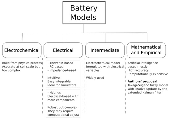
Figure 1.
Brief classification of battery models.
- (a)
- Electrochemical models:These models are built from the physics of electrochemical processes that occur at the battery cell level. They are quite accurate at this level [10,11,12,13,14,15,16], although they present significant errors at larger scales. In view of the above, its usefulness is justified to optimize the physical design of the cells [17]. These models are highly complex to define and implement, requiring a large computational burden, since they are usually described by nonlinear differential equations [10,18,19] that model microscopic transport phenomena or the chemical kinetics of the reactions involved [20,21]. However, recent research seeks to obtain low-order models for use in real-time applications [22]. The most common are usually single particle models [23], porous electrodes [24] and pseudo-two-dimensional models [9].
- (b)
- Electrical models:They are implemented by means of electrical circuits (resistors, capacitors and sources), to describe the behavior of a battery. They are usually intuitive models, and by their nature, they are directly applicable to the use of simulators where it is easy to integrate them with the rest of the participating systems. That is why their uses, in their different versions, are widespread. Most of these models can be grouped into a few categories:
- −
- Thevenin-based models [25,26,27,28]. These models basically consist of a real voltage source followed by a concatenation of n RC cells in series. The voltage source represents the open circuit voltage, , related to the state of charge (SOC) of the battery [29]. This model has a relatively uncomplicated design and demonstrates good accuracy in simulations [30]. In addition, it does not consider nonlinear behavior and temperature effects in batteries, although recent works are making improvements in this aspect [31]. A Thevenin-based model of n-RC order is shown in Figure 2, and its transfer function is shown in (1).
 Figure 2. Thevenin-based model of nth order RC cells.
 - −
- RC-based models [32,33,34]. These are simpler electronics models that basically consist of a network formed by two capacitors and several resistors. Generally, a large capacitor models the energy storage capacity of the battery, and another, smaller than the previous one, models its transient effects.
- −
- Impedance-based models [35,36,37]. These types of models change the RC cells of the Thevenin model by impedances determined by electrochemical impedance spectroscopy methods. They are usually suitable models for slow discharges but not for high currents.
Obviously, in the scientific literature, there are models that, trying to obtain better performance, hybridize the previous ones and introduce controlled sources and nonlinear elements [38,39] and even operators or mathematical blocks such as integrators and filters [40], obtaining general and robust models, although due to their complexity, they may require a lot of computational burden to adjust their parameters.We should also mention the so-called intermediate models, which are located between purely electrochemical and equivalent circuit models, although they are basically formulated with electrical variables [32]. The simplest is the Peukert model from 1897 [41], and among the most famous is the Shepherd model from 1965 [42], which is still widely used today, as well as their respective improvements in the Unnewehr, Nertst and Plett models [32,43,44,45]. Plett’s model can be considered an improved compendium of the previous ones; however, its improvement comes at the cost of increasing its complexity and requiring several parameters to be experimentally determined. - (c)
- Mathematical and empirical models: There are multiple techniques in the literature, most of them employing artificial intelligence techniques, that allow obtaining nonlinear models of dynamic systems with high accuracy, such as neural networks [46,47,48], neuro-fuzzy models [49], particle swarm optimization [50], or the most recent hybrid models [51,52], among others [53]. Many of these models (algorithms) have been used to estimate the LIB performance from operating data [50,54,55,56,57]. The goodness of these algorithms is more than proved, especially when they are based on a large set of data, but they do not allow these models to adapt to subsequent LIB changes.
The previous methodologies allow obtaining more or less accurate models, but they are unable to adapt to the changes in the dynamics that a LIB undergoes during its life cycle. The main objective of this work is to present an iterative modeling methodology, capable of improving an initial model with each new set of data obtained and, therefore, capable of adapting to such changes. In order to respond to these problems, the main novelty of the paper is the use of an iterative modeling technique, which allows a balanced solution in terms of modeling error and computational cost, as well as adaptability to changes in battery performance in demanding applications such as the one studied. In this paper, we propose the use of an extended Kalman filter (EKF) algorithm [58] as an iterative modeling algorithm to adapt a Takagi–Sugeno fuzzy model (TSFM) [59]. This combination provides the accuracy and interpretability of a fuzzy model, together with the adaptability and computational efficiency of the EKF [60], so that it is possible to maintain model accuracy in the face of dynamic variations experienced by the batteries during their operating cycle. In addition, it should also be noted that the EKF is particularly suitable for systems where noise or inaccuracies are present, making it ideal for real-world applications [61].
2. Materials and Methods
To evaluate and validate the adaptive capacity of the developed algorithm to model the LIB, two experimental tests (charging and discharging tests) were carried out on a VDC and 120 Ah LIB ( The battery used has the following characteristics: Pack lithium ion Samsung 50 59.2 V 120 Ah + BMS 80 A + aluminum box). Specifications of lithium Ion battery V 120 Ah—Samsung 50E. Technology: NMC. Battery pack nominal voltage: V. Battery pack charging voltage: V. Capacity: 120 Ah ( kWh). Continuous maximum discharge current: 240 A. In this case, the setting is 16 cells of V in series, and 24 cells of 5 Ah in parallel to obtain the 120 Ah., specially designed and manufactured from Samsung, model INR21700-50S cells by Batesur. For this purpose, simulations results of the proposed algorithm were compared with the experimental data obtained on the real battery. The model simulations were performed in the MATLAB environment. The sampling time during all tests was set at 1 s.
To evaluate the battery performance, in particular its voltage, with respect to its operating temperature, a temperature-controlled high-capacity thermal chamber was used. Specifically, during the two tests, different heating cycles were programmed up to a maximum internal temperature of 60 C, and a subsequent forced cooling of the battery, always taking into account the safety temperature limits established by the manufacturer. The cooling stage was carried out using a high-flow axial fan. The objective of the temperature control was never to reach a target temperature but to provoke substantial temperature variations in a short period of time, essential to appreciate the effect of the temperature on the voltage both in the training and validation phases of the model.
For the experimental tests, a 32 kW programmable source and sink of the Regatron TC.GSS series were used. This device allows operation in the first (source) and fourth (load) quadrant depending on the voltage set point and the current or power limits established. The electrical connection between the battery and the programmable source was made by direct connection using fuses. Due to the internal protections of the device, it was not necessary to add additional elements such as antireverse diodes. The charge and discharge profiles (current and power profiles, respectively) were previously defined in the software that includes the programmable source and executed directly on the final assembly. The measurement of the variables of interest, voltage, current and operating temperature of the battery was performed by means of specific sensors and a signal conditioning circuit designed ad hoc. For voltage and current measurements, Hall Effect sensors model LV25-P and LA25-P from LEM, respectively, were used. For temperature measurement, an NTC type thermoresistance and a conditioning circuit based on a resistive divider and zero correction circuit were used. To ensure an optimal and homogeneous measurement, the temperature sensor was placed in the center of the side face of the battery, at the opposite end of the thermal chamber heat source. The measurement obtained was compared at all times with a reference contact thermometer. The acquisition of the variables was carried out by means of a 12-bit resolution data acquisition card (DAQ) NI-USB-6008 from National Instruments. Their storage, processing and representation was carried out by means of a data acquisition and control system (SCADA) designed ad hoc and programmed in LabVIEW.The experimental setup carried out can be seen in Figure 3.
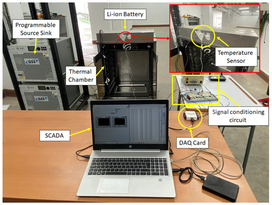
Figure 3.
Laboratory experimental setup.
2.1. Takagi–Sugeno Fuzzy Model
Fuzzy logic, unlike bi-evaluated logic, is able to work with infinite possible values, not only with ‘TRUE’ and ‘FALSE’. It is therefore very close to human reasoning, able to infer by vague predicates, i.e., able to logically integrate the infinite shades of gray that exist between absolute black and white. Fuzzy models are based on IF-THEN rules. The condition that must be fulfilled (the ‘IF’), is called the antecedent, and the one that is activated if the antecedent is fulfilled (the ‘THEN’), is the consequent. Between the different fuzzy models that exist, TSFM are those whose consequent is a linear polynomial [59,62], see (2)).
where n and m are respectively the number of input () and output () variables of a system to be modeled; represent the index of the rule and the total number of rules for the i-th output (, ). On the other hand, , is the parameters of the consequents, and k is the sampling time. are the fuzzy sets that define the antecedents of the fuzzy rules [63].
Obtaining an accurate model is a fundamental step to control any system. TSFM are universal approximators [64], allowing approximate reasoning [65], and have proven to be very accurate in modeling nonlinear systems [66,67,68,69]. Usually, the number of rules increases if the modeling error is to be reduced [70]; therefore, this process is crucial to obtain a good, accurate and manageable model for both analysis [71,72,73] and control system design [74,75].
To work with a more compact expression, the input vector could be extend [67,74] by the coordinate :
Thus, the output can be calculated by [76]:
where are variables coefficients [77]
and is the degree of activation of the fuzzy rules:
is the jth membership function in the l rule, for the ith output ( fuzzy set). The are the parameters of this membership functions. So, the modeling process consists of determining and parameters to obtain a TSFM.
2.2. Extended Kalman Filter and Its Application to Takagi–Sugeno Fuzzy Modeling
The EKF allows to construct a pseudo-optimum observer for nonlinear systems [58,78,79] (pseudo because it is based on a linear approximation). The filter is based on the assumption that the noises (uncertainties in the model and inaccuracies of the sensors) are zero mean white Gaussian noise, although there are also variants that allow working with other types of noise. It has shown that the EKF is an excellent algorithm for iteratively modeling complex systems based on data [60,61,80,81,82,83,84]. Therefore, in this work, it is used as an iterative adjustment method for the TSFM.
Be a nonlinear dynamical system in discrete time:
where is the state vector, is the input vector, and and are white noise vectors. The system’s Jacobian matrices are:
and
The EKF is considered as the execution of a prediction phase followed by an update phase. The prediction phase uses the state model and past data, while the update phase adds sensor information to the prediction—all this taking into account the quality of this information known through its covariance matrices. To solve the EKF, the following set of equations must be used iteratively:
Prediction (a priori estimation):
Update (a posteriori estimation):
From (11) to (15), represents the priori estimations of the true state , and represents the posteriori one.
and are, respectively, the a priori and the a posteriori estimate covariance matrices. are the estimated output vector, , and , are the noise covariance matrices, and is the Kalman gain.
Starting from an initial prediction , and its corresponding covariance matrix, , the algorithm evolves iteratively, minimizing the estimation error and its covariance matrix for the linearization obtained at each instant.
As shown in [60,61], the EKF algorithm allows to estimate the parameters of a TSFM. To do it, it is necessary to define a new model whose states are the parameters to be estimated [85], in (16), which will be adjusted iteratively to reduce the estimation error on the output to be modeled, . represents the uncertainty of the output measurements of the system, which are assumed to be a zero mean Gaussian white noise with covariance. So, Equations (11) to (15) can be iteratively applied to estimate the model’s parameters, .
In the above expressions, is the current estimation of , which includes all the TSFM parameters, both antecedent () and consequent (). is the derivative of the TSFM with respect to its parameters, which was obtained in [60], and its calculation was implemented in the Fuzzy Logic Tools library (FLT) [86].
3. Iterative Modeling of a Lithium-Ion Batteries
A LIB is a system whose parameters change over time due to degradation of its components or internal chemical processes, so a good prediction of its behavior requires the constant adjustment of the model. The conjunction of the Kalman algorithm with TSFM has demonstrated the ability to obtain good models while allowing to improve and adapt these models with each new data obtained from the operation of the system [60,61]. The use of such an algorithm for modeling the consequents of a TSFM based on operating data from a real LIB is presented below. It has been decided not to also adapt the antecedents of the TSFM in order to obtain a more efficient algorithm that can be executed iteratively at run time without requiring particularly fast hardware. Of course, if a more accurate model is required, it is possible to adapt the model antecedents as well [87].
The modeling process consisted of 4 phases:
3.1. Phase 1. Obtaining Discharge and Charge Data of a Real Battery
The first step is to obtain a sufficiently large and representative dataset of the LIB, taking that the data must be obtained in an operating environment as close as possible to that of a real EV into account. For this purpose, using the test bench presented in Section 2, the battery was discharged from its maximum capacity until it was completely discharged, and then it was subjected to a charging process. To do that, the “Worldwide Harmonised Light Vehicle Test Procedure” [88,89] (WLTP) was used for the discharge test. This procedure is used as a global standard to determine the CO emissions, fuel consumption and pollutant levels of traditional and hybrid cars, as well as the range of fully EVs. Specifically, based on the performance of the LIB, the WLTP standard was used assuming a low-power class 2 electric vehicle (with a power-to-mass ratio between 22 and 34 W/kg and a upper speed of less than 90 km/h). This driving profile is characterized by a speed and acceleration profile composed of three phases associated with low, medium, and high-speed driving, each with a defined duration, Figure 4. The associated discharge power profile was calculated from the acceleration profile, assuming a direct relationship between power and acceleration, matching the peak acceleration with the maximum allowable discharge power of the LIB. Due to the type of electric vehicle under study, in this test, only the discharge of the LIB has been considered. In Figure 4b, the negative accelerations present in the acceleration profile will not have any effect, as the battery recharging by means of regenerative systems is not considered. To evaluate the performance of the model, this power profile was evaluated over the entire operating range of the battery (0% ≤ SOC ≤ 100%). The described power profile is shown in Figure 5.
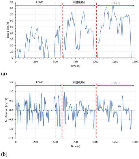
Figure 4.
WLTP class 2 driving profile: (a) speed; (b) acceleration.
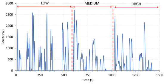
Figure 5.
Power profile for WLTP class 2 driving profile.
In accordance with the application and with the aim of evaluating the response of the modeling algorithm throughout the battery’s operating range, the LIB charging process was carried out by simulating the use of a commercial type 2 semifast charger. For this purpose, a charging test was performed for a maximum current of 35 A, according to the well-known two-phase charging protocol, constant current (Bulk Phase) and constant voltage (Absorption Phase).
In this first phase, a set of 86508 data sampled every second was obtained from the battery voltage, current, temperature and SOC (The battery SOC was estimated by integration of the current according to the Coulomb counting method [90].). These data are shown in Figure 6.
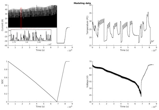
Figure 6.
Modeling data.
3.2. Phase 2. Initial TSFM
To obtain an initial structure of the dynamic model for the LIB similar to (7), a series of tests were performed on a reduced dataset consisting of the first 1000 data. Through these tests, it was determined to perform a third-order discrete dynamic model, i.e., including as inputs three memories of the previous outputs, together with the inputs (current, temperature, and SOC), and a memory of the current. That is, the discrete dynamic model of the system will have the form:
where k is the discrete time, is the estimate future voltage, ) are the previous voltages, and are the current and its previous value, is the temperature, and is the estimated SOC. f is the TSFM to be fitted.
Once the model structure was determined, the dataset was used to obtain an initial TSFM using the well-known subtractive clustering algorithm of Chiu [91]. Using a Cluster center’s range of influence (RADII) of , six rules with Gaussian antecedents were obtained.
3.3. Phase 3. Iterative Modeling
This is the most relevant phase of the experiment, since the objective of the present work is to demonstrate that it is possible to perform an iterative modeling that allows readjusting an existing model based on the new data obtained.
With the initial model obtained in the previous phase, the EKF was applied to improve the estimation of the parameters with each of the data, i.e., iteratively as it would be improved in a working system. The initial covariance matrix of the EKF, , was initialized as , this is , being an identity matrix. The fitting process is shown in Algorithm 1, where is a value indicating the reliability on the initial parameters of the model.
| Algorithm 1 EKF algorithm for the adaptation of consequents. |
A Mean Absolute Error (MAE) of mV, or the equivalent Root Mean Square Error (RMSE) of mV, was obtained during the modeling phase.
The prediction of the model at each iteration can be seen in Figure 7, and the error obtained at each instant can be seen in Figure 8.
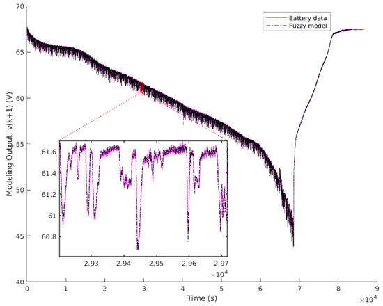
Figure 7.
Modeling output.
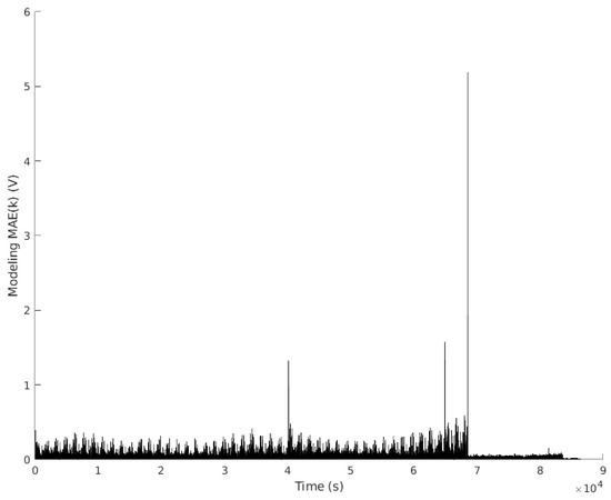
Figure 8.
Modeling error.
The model improves as new data appears. When a new behavior not yet modeled occurs, an error is raised, as can be seen in Figure 8. However, the algorithm will learn from this error and will improve the model.
The fuzzy model obtained after running through all the experimental data is reflected by the following rules, where GAUSS(c, ) is the Gauss function (this antecedents can be seen in Figure 9):
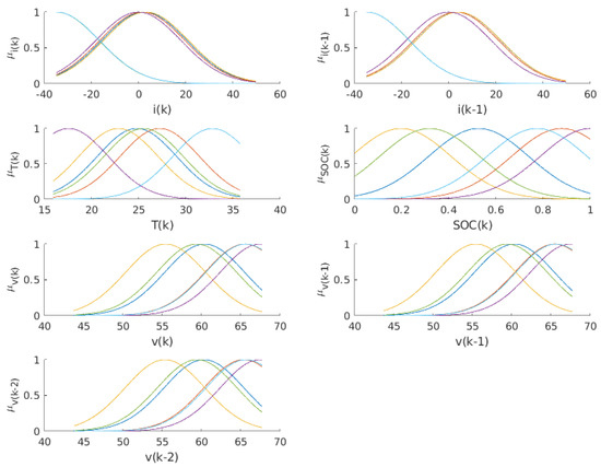
Figure 9.
TSFM antecedents.
IF is GAUSS(2.317; 25.41) and is GAUSS(3.925; 25.41)
and is GAUSS(24.8; 5.94) and is GAUSS(0.526; 0.3)
and is GAUSS(60.39; 7.187) and is GAUSS(60.33; 7.187) and is GAUSS(60.3; 7.187)
THEN = 9.007 −0.03385 +0.02963 +0.0007178 +2.638 +0.6987 −0.3983 +0.527
IF is GAUSS(1.501; 25.41) and is GAUSS(3.032; 25.41)
and is GAUSS(27.22; 5.94) and is GAUSS(0.878; 0.3)
and is GAUSS(65.51; 7.187) and is GAUSS(65.47; 7.187) and is GAUSS(65.38; 7.187)
THEN = 0.08457 −0.03393 +0.03365 +0.00247 +0.08013 +0.8829 −0.4889 +0.6025
IF is GAUSS(3.032; 25.41) and is GAUSS(4.027; 25.41)
and is GAUSS(22.84; 5.94) and is GAUSS(0.197; 0.3)
and is GAUSS(55.41; 7.187) and is GAUSS(55.42; 7.187) and is GAUSS(55.33; 7.187)
THEN = 0.1629 −0.03028 +0.03077 +0.00001303 +0.1531 +0.8291 −0.03837 +0.2058
IF is GAUSS(−0.158; 25.41) and is GAUSS(−0.158; 25.41)
and is GAUSS(17.56; 5.94) and is GAUSS(1; 0.3)
and is GAUSS(67.44; 7.187) and is GAUSS(67.44; 7.187) and is GAUSS(67.44; 7.187)
THEN = 1.453 −0.04581 +0.04429 −0.0007327 +0.3583 +0.6178 −0.3521 +0.7076
IF is GAUSS(−34.87; 25.41) and is GAUSS(−34.87; 25.41)
and is GAUSS(25.5; 5.94) and is GAUSS(0.318; 0.3)
and is GAUSS(59.38; 7.187) and is GAUSS(59.43; 7.187) and is GAUSS(59.43; 7.187)
THEN = 1.598 +0.1012 −0.08297 +0.0002574 +0.2328 +1.248 −1.106 +0.8397
IF is GAUSS(-34.77; 25.41) and is GAUSS(−34.9; 25.41)
and is GAUSS(32.82; 5.94) and is GAUSS(0.774; 0.3)
and is GAUSS(65.61; 7.187) and is GAUSS(65.61; 7.187) and is GAUSS(65.64; 7.187)
THEN = 0.2383 +0.08311 −0.08389 −0.0001479 +0.06106 +1.446 −1.274 +0.8237
This model allows us to interpret the relationships between the variables linguistically within each rule. In this case, the initial model was not considered to be easily interpretable as a whole, so the antecedents appear overlapped, but there are algorithms that allow this to be done [92,93,94].
3.4. Phase 4. Validation Data
Using the same philosophy as previous modeling data, a new charge/discharge cycle was performed to obtain another dataset to validate the resulting TSFM. On this occasion, 14746 data were obtained with the same sample time of 1 s, which are shown in Figure 10. The final TSFM obtained in the previous phase was validated to check the performance of the iterative algorithm.
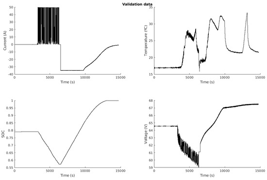
Figure 10.
Validation data.
4. Analysis of the Results
Finally, once all the data were run through, it was checked that the model obtained adequately represented the dynamic behavior of the battery under study. Note that the proposed algorithm does not perform the modeling with all the data, but iteratively adjusts the model with each new data obtained. Therefore, the main objective is not focused on obtaining a lower error rate than those obtained by other techniques presented in the scientific literature, but to demonstrate that the algorithm is able to perform the iterative adjustment, with good performance considering the model error, against diverse and highly fluctuating power profiles, regardless of the battery temperature, SOC or operating condition (charge or discharge). Obviously, the performance of the modeling process will be highly dependent on the initial model. In this case, for the test performed, the initial model was obtained from the clustering, without any additional tuning. Despite this, the model validation obtained a MAE of mV, and a RMSE of mV. The model output during the validation process is shown in Figure 11, and the error in Figure 12.
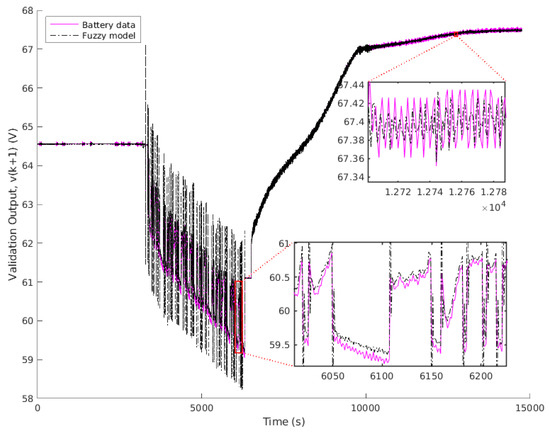
Figure 11.
Validation output.
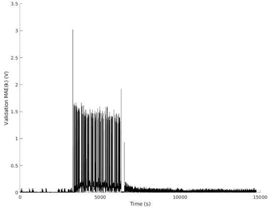
Figure 12.
Validation error.
From the results obtained, it is verified that the EKF works properly, and that it allows modeling iteratively a real LIB with a reduced error. This will allow continuous improvement and adaptation of the TSFM to the variations that the LIB may undergo.
5. Conclusions and Future Works
The modeling process of a LIB is a complex task that requires a deep knowledge of the laws of electrochemistry but is essential for its efficient use and proper management. For EVs application, the high fluctuation of the power profile means that the dynamic behavior of the LIB is strongly influenced by intrinsic nonlinearities. The main proposals found in the scientific literature for these applications are based on equivalent electrical models that present reduced performance in terms of dynamic behavior and in many cases, for the sake of simplicity, ignore the dependence on certain parameters such as temperature.
To address to the shortcomings found in terms of modeling, this research has applied an iterative fuzzy modeling methodology based on the EKF to a real LIB for use in EVs. The proposed method is not a closed algorithm and can be easily applied to other types of batteries or applications. The model parameters were fitted iteratively from an initial unfitted model, using a VDC and 120 Ah commercial LIB on a profile under WLTP standard conditions for a class 2 driving cycle. Experimental results for both charging and discharging, for the entire useful operating range of the LIB and different operating SOC and temperatures, validate the effectiveness of the model in a WLTP test resulting a MAE below 70 mV (about 21 mV RMSE) and taking into account that the starting model was unadjusted.
Based on the results, it is found that the designed algorithm and the obtained dynamic model are sufficiently accurate to iteratively model nonlinear LIBs even under such demanding operating profiles. Similarly, thanks to the iterative run-time fuzzy modeling methodology proposed in this work, the model can adapt to changes in the LIB’s performance or rated capacity due to usage time. This will contribute to the design and development of model-based energy management strategies and controllers for the proper operation of LIBs in EVs applications throughout their lifetime.
Further experiments and verifications will be carried out in the future to test the effectiveness of the proposed method for different driving cycle profiles and operating conditions, as well as its application for the design of iterative model-based SOC estimators. Finally, as a natural outcome of the research process, these models will be applied in the design of new model-based energy management and control strategies for use in hybrid EVs powered by LIBs hybridized with traditional combustion engines and/or hydrogen fuel cells.
Author Contributions
Conceptualization, F.J.V., J.M.E. and F.S.; Methodology, A.J.B., F.J.V., J.M.E. and F.S.; Software, A.J.B.; Validation, A.J.B., F.J.V., J.M.E.; Formal analysis, A.J.B., F.J.V., J.M.E. and F.S.; Investigation, A.J.B., F.J.V., J.M.E. and F.S.; Data curation, A.J.B., F.J.V., J.M.E.; Writing—original draft, A.J.B., F.J.V., J.M.E.; Writing—review & editing, A.J.B., F.J.V., J.M.E. and F.S.; Visualization, F.J.V. and J.M.E.; Supervision, J.M.A.; Project administration, J.M.A.; Funding acquisition, J.M.A. All authors have read and agreed to the published version of the manuscript.
Funding
This research was funded by “H2Integration&Control. Integration and Control of a hydrogen-based pilot plant in residential applications for energy supply” from the Spanish Government (PID2020-116616RB-C31), “SALTES: Smartgrid with reconfigurable Architecture for testing control Techniques and Energy Storage priority” by Andalusian Regional Program of R+D+i (P20-00730), and by the project “The green hydrogen vector. Residential and mobility application”, approved in the call for research projects of the Cepsa Foundation Chair of the University of Huelva.
Data Availability Statement
The data is available upon request to the authors.
Conflicts of Interest
The authors declare no conflict of interest.
Abbreviations
The following abbreviations are used in this manuscript:
| Acronym or Parameter | Description |
| Fuzzy antecedent for rule l, derivative i and input j. | |
| Consequents parameters of the fuzzy model | |
| DAQ | data acquisition |
| Derivative of the fuzzy model (output matrix of the EKF model) | |
| EKF | Extended Kalman filter |
| EVs | Electric vehicles |
| LIB | Lithium-ion battery |
| MAE | Mean Absolute Error |
| n | System order (length of the state vector) |
| Covariance matrix of the Kalman filter | |
| Vector of parameters to be estimated | |
| Vector of estimated parameters | |
| RADII | Cluster center’s range of influence parameter |
| RMSE | Root Mean Square Error |
| SCADA | Supervisory control and data acquisition system |
| SOC | Battery State of Charge |
| TSFM | Takagi–Sugeno fuzzy model |
| WLTP | Worldwide Harmonised Light Vehicle Test Procedure standard |
| State vector | |
| Extended state vector | |
| Output of the actual system | |
| Estimated output |
References
- Philippot, M.; Alvarez, G.; Ayerbe, E.; Mierlo, J.V.; Messagie, M. Eco-efficiency of a lithium-ion battery for electric vehicles: Influence of manufacturing country and commodity prices on ghg emissions and costs. Batteries 2019, 5, 23. [Google Scholar] [CrossRef]
- Lowe, I. How Planning Can Address the Challenge of Transitioning to Low-Carbon Urban Economies. In Proceedings of the The Routledge Handbook of Australian Urban and Regional Planning; Routledge: New York, NY, USA, 2017. [Google Scholar]
- Sajadi-Alamdari, S.A.; Voos, H.; Darouach, M. Nonlinear model predictive extended eco-cruise control for battery electric vehicles. In Proceedings of the 2016 24th Mediterranean Conference on Control and Automation (MED), Athens, Greece, 21–24 June 2016; pp. 467–472. [Google Scholar] [CrossRef]
- Tehrani, K. A smart cyber physical multi-source energy system for an electric vehicle prototype. J. Syst. Archit. 2020, 111, 101804. [Google Scholar] [CrossRef]
- Mao, N.; Wang, Z.R.; Chung, Y.H.; Shu, C.M. Overcharge cycling effect on the thermal behavior, structure, and material of lithium-ion batteries. Appl. Therm. Eng. 2019, 163, 114147. [Google Scholar] [CrossRef]
- Ren, D.; Hsu, H.; Li, R.; Feng, X.; Guo, D.; Han, X.; Lu, L.; He, X.; Gao, S.; Hou, J.; et al. A comparative investigation of aging effects on thermal runaway behavior of lithium-ion batteries. eTransportation 2019, 2, 100034. [Google Scholar] [CrossRef]
- Tran, M.K.; Dacosta, A.; Mevawalla, A.; Panchal, S.; Fowler, M. Comparative study of equivalent circuit models performance in four common lithium-ion batteries: LFP, NMC, LMO, NCA. Batteries 2021, 7, 51. [Google Scholar] [CrossRef]
- Cittanti, D.; Ferraris, A.; Airale, A.; Fiorot, S.; Scavuzzo, S.; Carello, M. Modeling Li-ion batteries for automotive application: A trade-off between accuracy and complexity. In Proceedings of the 2017 International Conference of Electrical and Electronic Technologies for Automotive, Antalya, Turkey, 21–23 August 2017; pp. 1–8. [Google Scholar] [CrossRef]
- Jokar, A.; Rajabloo, B.; Désilets, M.; Lacroix, M. Review of simplified Pseudo-two-Dimensional models of lithium-ion batteries. J. Power Sources 2016, 327, 44–55. [Google Scholar] [CrossRef]
- Hu, Y.; Yurkovich, S.; Guezennec, Y.; Yurkovich, B. A technique for dynamic battery model identification in automotive applications using linear parameter varying structures. Control Eng. Pract. 2009, 17, 1190–1201. [Google Scholar] [CrossRef]
- Liu, K.; Gao, Y.; Zhu, C.; Li, K.; Fei, M.; Peng, C.; Zhang, X.; Han, Q.L. Electrochemical modeling and parameterization towards control-oriented management of lithium-ion batteries. Control Eng. Pract. 2022, 124, 105176. [Google Scholar] [CrossRef]
- Madani, S.S.; Schaltz, E.; Kær, S.K. Review of parameter determination for thermal modeling of lithium ion batteries. Batteries 2018, 4, 20. [Google Scholar] [CrossRef]
- Mathew, M.; Mastali, M.; Catton, J.; Samadani, E.; Janhunen, S.; Fowler, M. Development of an electro-thermal model for electric vehicles using a design of experiments approach. Batteries 2018, 4, 29. [Google Scholar] [CrossRef]
- Smith, K.A.; Rahn, C.D.; Wang, C.Y. Model-Based Electrochemical Estimation and Constraint Management for Pulse Operation of Lithium Ion Batteries. IEEE Trans. Control. Syst. Technol. 2010, 18, 654–663. [Google Scholar] [CrossRef]
- Sikha, G.; White, R.E.; Popov, B.N. A Mathematical Model for a Lithium-Ion Battery/Electrochemical Capacitor Hybrid System. J. Electrochem. Soc. 2005, 152, A1682. [Google Scholar] [CrossRef]
- Torchio, M.; Magni, L.; Gopaluni, R.B.; Braatz, R.D.; Raimondo, D.M. LIONSIMBA: A Matlab Framework Based on a Finite Volume Model Suitable for Li-Ion Battery Design, Simulation, and Control. J. Electrochem. Soc. 2016, 163, A1192–A1205. [Google Scholar] [CrossRef]
- Dees, D.W.; Battaglia, V.S.; Bélanger, A. Electrochemical modeling of lithium polymer batteries. J. Power Sources 2002, 110, 310–320. [Google Scholar] [CrossRef]
- Shafiei, A.; Momeni, A.; Williamson, S.S. Battery modeling approaches and management techniques for Plug-in Hybrid Electric Vehicles. In Proceedings of the 2011 IEEE Vehicle Power and Propulsion Conference, Chicago, IL, USA, 6–9 September 2011; pp. 1–5. [Google Scholar] [CrossRef]
- Kim, T.; Qiao, W. A Hybrid Battery Model Capable of Capturing Dynamic Circuit Characteristics and Nonlinear Capacity Effects. IEEE Trans. Energy Convers. 2011, 26, 1172–1180. [Google Scholar] [CrossRef]
- Chu, Z.; Jobman, R.; Rodríguez, A.; Plett, G.L.; Trimboli, M.S.; Feng, X.; Ouyang, M. A control-oriented electrochemical model for lithium-ion battery. Part II: Parameter identification based on reference electrode. J. Energy Storage 2020, 27, 101101. [Google Scholar] [CrossRef]
- Song, L.; Evans, J.W. Electrochemical-Thermal Model of Lithium Polymer Batteries. J. Electrochem. Soc. 2000, 147, 2086. [Google Scholar] [CrossRef]
- Hu, Y.; Yin, Y.; Bi, Y.; Choe, S.Y. A control oriented reduced order electrochemical model considering variable diffusivity of lithium ions in solid. J. Power Sources 2020, 468, 228322. [Google Scholar] [CrossRef]
- Tran, N.T.; Vilathgamuwa, M.; Farrell, T.; Choi, S.S. Matlab simulation of lithium ion cell using electrochemical single particle model. In Proceedings of the 2016 IEEE 2nd Annual Southern Power Electronics Conference (SPEC), Auckland, New Zealand, 5–8 December 2016. [Google Scholar] [CrossRef]
- Lai, W.; Ciucci, F. Mathematical modeling of porous battery electrodes—Revisit of Newman’s model. Electrochim. Acta 2011, 56, 4369–4377. [Google Scholar] [CrossRef]
- Sockeel, N.; Shahverdi, M.; Mazzola, M.; Meadows, W. High-fidelity battery model for model predictive control implemented into a plug-in hybrid electric vehicle. Batteries 2017, 3, 13. [Google Scholar] [CrossRef]
- Salameh, Z.; Casacca, M.; Lynch, W. A mathematical model for lead-acid batteries. IEEE Trans. Energy Convers. 1992, 7, 93–98. [Google Scholar] [CrossRef]
- Barletta, G.; DiPrima, P.; Papurello, D. Thevenin’s Battery Model Parameter Estimation Based on Simulink. Energies 2022, 15, 6207. [Google Scholar] [CrossRef]
- Wang, C.; Xu, M.; Zhang, Q.; Feng, J.; Jiang, R.; Wei, Y.; Liu, Y. Parameters identification of Thevenin model for lithium-ion batteries using self-adaptive Particle Swarm Optimization Differential Evolution algorithm to estimate state of charge. J. Energy Storage 2021, 44, 103244. [Google Scholar] [CrossRef]
- Baczyńska, A.; Niewiadomski, W.; Gonçalves, A.; Almeida, P.; Luís, R. LI-NMC batteries model evaluation with experimental data for electric vehicle application. Batteries 2018, 4, 11. [Google Scholar] [CrossRef]
- Zhou, W.; Zheng, Y.; Pan, Z.; Lu, Q. Review on the Battery Model and SOC Estimation Method. Processes 2021, 9, 1685. [Google Scholar] [CrossRef]
- Ding, X.; Zhang, D.; Cheng, J.; Wang, B.; Luk, P.C.K. An improved Thevenin model of lithium-ion battery with high accuracy for electric vehicles. Appl. Energy 2019, 254, 113615. [Google Scholar] [CrossRef]
- Jiang, J.; Zhang, C. Fundamentals and Applications of Lithium-Ion Batteries in Electric Drive Vehicles; Wiley: Hoboken, NJ, USA, 2015. [Google Scholar] [CrossRef]
- He, H.; Xiong, R.; Fan, J. Evaluation of Lithium-Ion Battery Equivalent Circuit Models for State of Charge Estimation by an Experimental Approach. Energies 2011, 4, 582–598. [Google Scholar] [CrossRef]
- Bhangu, B.; Bentley, P.; Stone, D.; Bingham, C. Nonlinear Observers for Predicting State-of-Charge and State-of-Health of Lead-Acid Batteries for Hybrid-Electric Vehicles. IEEE Trans. Veh. Technol. 2005, 54, 783–794. [Google Scholar] [CrossRef]
- Dubarry, M.; Liaw, B.Y. Development of a universal modeling tool for rechargeable lithium batteries. J. Power Sources 2007, 174, 856–860. [Google Scholar] [CrossRef]
- Danzer, M.; Liebau, V.; Maglia, F. Aging of lithium-ion batteries for electric vehicles. In Advances in Battery Technologies for Electric Vehicles; Elsevier: Amsterdam, The Netherlands, 2015; pp. 359–387. [Google Scholar] [CrossRef]
- Liaw, B.Y.; Jungst, R.G.; Nagasubramanian, G.; Case, H.L.; Doughty, D.H. Modeling capacity fade in lithium-ion cells. J. Power Sources 2005, 140, 157–161. [Google Scholar] [CrossRef]
- Chen, M.; Rincon-Mora, G. Accurate electrical battery model capable of predicting runtime and I-V performance. IEEE Trans. Energy Convers. 2006, 21, 504–511. [Google Scholar] [CrossRef]
- Li, C.; Cui, N.; Cui, Z.; Wang, C.; Zhang, C. Novel equivalent circuit model for high-energy lithium-ion batteries considering the effect of nonlinear solid-phase diffusion. J. Power Sources 2022, 523, 230993. [Google Scholar] [CrossRef]
- Tremblay, O.; Dessaint, L.A. Experimental Validation of a Battery Dynamic Model for EV Applications. World Electr. Veh. J. 2009, 3, 289–298. [Google Scholar] [CrossRef]
- Peukert, W. Über die Abhängigkeit der Kapazität von der Entladestromstärke bei Bleiakkumulatoren. Elektrotechnisch Z. 1897, 20, 287–288. (In German) [Google Scholar]
- Shepherd, C.M. Design of Primary and Secondary Cells. J. Electrochem. Soc. 1965, 112, 657. [Google Scholar] [CrossRef]
- Degla, A.; Chikh, M.; Mahrane, A.; Arab, A.H. Improved lithium-ion battery model for photovoltaic applications based on comparative analysis and experimental tests. Int. J. Energy Res. 2022, 46, 10965–10988. [Google Scholar] [CrossRef]
- Hussein, A.A.H.; Batarseh, I. An overview of generic battery models. In Proceedings of the 2011 IEEE Power and Energy Society General Meeting, Detroit, MI, USA, 24–29 July 2011. [Google Scholar] [CrossRef]
- He, H.; Xiong, R.; Guo, H.; Li, S. Comparison study on the battery models used for the energy management of batteries in electric vehicles. Energy Convers. Manag. 2012, 64, 113–121. [Google Scholar] [CrossRef]
- Denaï, M.A.; Palis, F.; Zeghbib, A.H. Modeling and control of non-linear systems using soft computing techniques. Appl. Soft Comput. 2007, 7, 728–738. [Google Scholar] [CrossRef]
- Jang, J.S.R. ANFIS: Adaptive–network-based fuzzy inference system. IEEE Trans. Syst. Man Cybern. 1993, 23, 665–685. [Google Scholar] [CrossRef]
- Zhang, C.W.; Chen, S.R.; Gao, H.B.; Xu, K.J.; Yang, M.Y. State of charge estimation of power battery using improved back propagation neural network. Batteries 2018, 4, 69. [Google Scholar] [CrossRef]
- Jang, J.S.R.; Sun, C.T. Neuro-fuzzy modeling and control. Proc. IEEE 1995, 83, 378–406. [Google Scholar] [CrossRef]
- Xiong, R.; He, H.; Guo, H.; Ding, Y. Modeling for Lithium-Ion Battery used in Electric Vehicles. Procedia Eng. 2011, 15, 2869–2874. [Google Scholar] [CrossRef]
- Casteleiro-Roca, J.L.; Barragán, A.J.; Segura, F.; Calvo-Rolle, J.L.; Andújar, J.M. Intelligent hybrid system for the prediction of the voltage-current characteristic curve of a hydrogen-based fuel cell. Rev. Iberoam. Autom. ÁTica Inform. ÁTica Ind. 2019, 16, 492–501. [Google Scholar] [CrossRef]
- Casteleiro-Roca, J.; Barragán, A.J.; Segura, F.; Calvo-Rolle, J.L.; Andújar, J.M. Fuel Cell Output Current Prediction with a Hybrid Intelligent System. Complexity 2019, 2019, 10. [Google Scholar] [CrossRef]
- Miao, J.; Tong, Z.; Tong, S.; Zhang, J.; Mao, J. State of Charge Estimation of Lithium-Ion Battery for Electric Vehicles under Extreme Operating Temperatures Based on an Adaptive Temporal Convolutional Network. Batteries 2022, 8, 145. [Google Scholar] [CrossRef]
- He, W.; Williard, N.; Chen, C.; Pecht, M. State of charge estimation for Li-ion batteries using neural network modeling and unscented Kalman filter-based error cancellation. Int. J. Electr. Power Energy Syst. 2014, 62, 783–791. [Google Scholar] [CrossRef]
- How, D.N.T.; Hannan, M.A.; Hossain Lipu, M.S.; Ker, P.J. State of Charge Estimation for Lithium-Ion Batteries Using Model-Based and Data-Driven Methods: A Review. IEEE Access 2019, 7, 136116–136136. [Google Scholar] [CrossRef]
- Singh, P.; Vinjamuri, R.; Wang, X.; Reisner, D. Design and implementation of a fuzzy logic-based state-of-charge meter for Li-ion batteries used in portable defibrillators. J. Power Sources 2006, 162, 829–836. [Google Scholar] [CrossRef]
- Tong, S.; Lacap, J.H.; Park, J.W. Battery state of charge estimation using a load-classifying neural network. J. Energy Storage 2016, 7, 236–243. [Google Scholar] [CrossRef]
- Kalman, R.E. A new approach to linear filtering and prediction problems. Trans. -Asme-J. Basic Eng. 1960, 82, 35–45. [Google Scholar] [CrossRef]
- Takagi, T.; Sugeno, M. Fuzzy identification of systems and its applications to modeling and control. IEEE Trans. Syst. Man Cybern. 1985, 15, 116–132. [Google Scholar] [CrossRef]
- Barragán, A.J.; Al-Hadithi, B.M.; Jiménez, A.; Andújar, J.M. A general methodology for online TS fuzzy modeling by the extended Kalman filter. Appl. Soft Comput. 2014, 18, 277–289. [Google Scholar] [CrossRef]
- Barragán, A.; Enrique, J.; Segura, F.; Andújar, J. Iterative Fuzzy Modeling Of Hydrogen Fuel Cells By The Extended Kalman Filter. IEEE Access 2020, 8, 180280–180294. [Google Scholar] [CrossRef]
- Babuška, R. Fuzzy modeling-A control engineering perspective. In Proceedings of the 1995 IEEE International Conference on Fuzzy Systems, Yokohama, Japan, 20–24 March 1995; Volume 4, pp. 1897–1902. [Google Scholar] [CrossRef]
- Barragán, A.J.; Andújar, J.M.; Aznar, M.; Jiménez, A. Methodology for adapting the parameters of a fuzzy system using the extended Kalman filter. In European Society for Fuzzy Logic and Technology (EUSFLAT-2011) and LFA-2011; Galichet, S., Montero, J., Mauris, G., Eds.; Number 1 in Advances in Intelligent Systems Research: Dordrecht, The Netherlands, 2011; pp. 686–690. [Google Scholar] [CrossRef]
- Zeng, K.; Zhang, N.Y.; Xu, W.L. A comparative study on sufficient conditions for Takagi–Sugeno fuzzy systems as universal approximators. IEEE Trans. Fuzzy Syst. 2000, 8, 773–780. [Google Scholar] [CrossRef]
- Zadeh, L.A. Fuzzy sets. Inf. Control 1965, 8, 338–353. [Google Scholar] [CrossRef]
- Sanz, R.; Matia, F.; de Antonio, A.; Segarra, M.J. Fuzzy agents for ICa. In Proceedings of the 1998 IEEE International Conference on Fuzzy Systems, IEEE World Congress on Computational Intelligence, Kota Kinabalu, Malaysia, 3–5 December 2014; Anon, Ed.; IEEE: Piscataway, NJ, USA; Anchorage, AK, USA, 1998; Volume 1, pp. 545–550. [Google Scholar] [CrossRef]
- Andújar, J.M.; Barragán, A.J. A methodology to design stable nonlinear fuzzy control systems. Fuzzy Sets Syst. 2005, 154, 157–181. [Google Scholar] [CrossRef]
- Al-Hadithi, B.M.; Jiménez, A.; Matía, F. A new approach to fuzzy estimation of Takagi–Sugeno model and its applications to optimal control for nonlinear systems. Appl. Soft Comput. 2012, 12, 280–290. [Google Scholar] [CrossRef]
- Doubabi, H.; Ezzara, A.; Salhi, I. Simulation and Experimental Validation for Takagi-Sugeno Fuzzy-Based Li-ion Battery Model. Int. J. Renew. Energy Res. 2022, 12, 339–348. [Google Scholar] [CrossRef]
- Kóczy, L.T.; Hirota, K. Size reduction by interpolation in fuzzy rule bases. IEEE Trans. Syst. Man -Cybern. -Part B Cybern. 1997, 27, 14–25. [Google Scholar] [CrossRef] [PubMed]
- Andújar, J.M.; Barragán, A.J. Hybridization of fuzzy systems for modeling and control. Rev. Iberoam. AutomáTica InformáTica Ind. {RIAI} 2014, 11, 127–141. [Google Scholar] [CrossRef]
- Barragán, A.J.; Al-Hadithi, B.M.; Andújar, J.M.; Jiménez, A. Formal methodology for analyzing the dynamic behavior of nonlinear systems using fuzzy logic. Rev. Iberoam. AutomÁTica InformÁTica Ind. (Riai) 2015, 12, 434–445. [Google Scholar] [CrossRef]
- Barragán, A.J.; Enrique, J.M.; Calderón, A.J.; Andújar, J.M. Discovering the dynamic behavior of unknown systems using fuzzy logic. Fuzzy Optim. Decis. Mak. 2018, 1–25. [Google Scholar] [CrossRef]
- Márquez, J.M.A.; Piña, A.J.B.; Arias, M.E.G. A general and formal methodology for designing stable nonlinear fuzzy control systems. IEEE Trans. Fuzzy Syst. 2009, 17, 1081–1091. [Google Scholar] [CrossRef]
- Al-Hadithi, B.M.; Barragán, A.J.; Andújar, J.M.; Jiménez, A. Fuzzy Optimal Control for Double Inverted Pendulum. In Proceedings of the 7th IEEE Conference on Industrial Electronics and Applications (ICIEA 2012), Singapore, 18–20 July 2012. [Google Scholar]
- Wang, L.X. A Course in Fuzzy Systems and Control; Prentice Hall: Hoboken, NJ, USA, 1997. [Google Scholar]
- Wong, L.; Leung, F.; Tam, P. Stability design of TS model based fuzzy systems. In Proceedings of the IEEE International Conference on Fuzzy Systems, Barcelona, Spain, 5 July 1997; Volume 1, pp. 83–86. [Google Scholar] [CrossRef]
- Kalman, R.E. New Methods in Wiener Filtering Theory. In Proceedings of the 1st Symposium On Engineering Applications of Random Function Theory and Probability; Bogdanoff, J.L., Kozin, F., Eds.; John Wiley and Sons: New York, NY, USA, 1963. [Google Scholar]
- Maybeck, P.S. Stochastic Models, Estimation, and Control; Mathematics in Science and Engineering; Academyc Press: New York, NY, USA, 1979; Volume 141. [Google Scholar]
- Al-Hadithi, B.M.; Jiménez, A.; Matía, F.; Andújar, J.M.; Barragán, A.J. New Concepts for the Estimation of Takagi–Sugeno Model Based on Extended Kalman Filter. In Fuzzy Modeling and Control: Theory and Applications; Matía, F., Marichal, G.N., Jiménez, E., Eds.; Atlantis Computational Intelligence Systems; Atlantis Press: Dordrecht, The Netherlands, 2014; Chapter 1; Volume 9, pp. 3–24. [Google Scholar] [CrossRef]
- Al-Hadithi, B.M.; Jiménez Avello, A.; Matía, F. New Methods for the Estimation of Takagi–Sugeno Model Based Extended Kalman Filter and its Applications to Optimal Control for Nonlinear Systems. Optim. Control. Appl. Methods 2012, 33, 552–575. [Google Scholar] [CrossRef]
- Chafaa, K.; Ghanaï, M.; Benmahammed, K. Fuzzy modelling using Kalman filter. IET Control Theory Appl. 2007, 1, 58–64. [Google Scholar] [CrossRef]
- Simon, D. Kalman filtering with state constraints: A survey of linear and nonlinear algorithms. IET Control Theory Appl. 2010, 4, 1303–1318. [Google Scholar] [CrossRef]
- Ketabipour, S.; Samet, H.; Vafamand, N. TS Fuzzy Prediction-based SVC Compensation of Wind Farms Flicker: A Dual-UKF Approach. CSEE J. Power Energy Syst. 2022, 8, 1594–1602. [Google Scholar] [CrossRef]
- Simon, D. Training fuzzy systems with the extended Kalman filter. Fuzzy Sets Syst. 2002, 132, 189–199. [Google Scholar] [CrossRef]
- Barragán, A.J.; Andújar, J.M. Fuzzy Logic Tools Reference Manual v1.0; University of Huelva: Huelva, Spain, 2012. [Google Scholar]
- Matía, F.; Marichal, G.N.; Jiménez, E. (Eds.) Fuzzy Modeling and Control: Theory and Applications; Atlantis Computational Intelligence Systems; Atlantis Press: Dordrecht, The Netherlands, 2014; Volume 9. [Google Scholar] [CrossRef]
- Economic and Social Council, United Nations Economic Commission for Europe. Proposal for a New Global Technical Regulation on the Worldwide Harmonized Light Vehicles Test Procedure (WLTP); World Forum for Harmonization of Vehicle Regulations: Geneva, Switzerland, 2013. [Google Scholar]
- (UNECE), U.N.E.C.f.E. Parameter List for RLD-Validation (WLTP-DTP-10-08, WLTP-DTP). Available online: http://www.unece.org/fileadmin/DAM/trans/doc/2012/wp29grpe/WLTP-DHC-12-07e.xls (accessed on 27 December 2022).
- Vivas, F.; Segura, F.; Andújar, J.; Caparrós, J. A suitable state-space model for renewable source-based microgrids with hydrogen as backup for the design of energy management systems. Energy Convers. Manag. 2020, 219, 113053. [Google Scholar] [CrossRef]
- Chiu, S. Fuzzy model identification based on cluster estimation. J. Intell. Fuzzy Syst. 1994, 2, 267–278. [Google Scholar] [CrossRef]
- Johansen, T.A.; Shorten, R.N.; Murray-Smith, R. On the interpretation and identification of dynamic Takagi–Sugeno fuzzy models. IEEE Trans. Fuzzy Syst. 2000, 8, 297–313. [Google Scholar] [CrossRef] [PubMed]
- Vélez, M.A.; Sánchez, O.; Romero, S.; Manuel, A.J. A new methodology to improve interpretability in neuro-fuzzy TSK models. Appl. Soft Comput. 2010, 10, 578–591. [Google Scholar] [CrossRef]
- Díez, J.L.; Navarro, J.L.; Sala, A. A fuzzy clustering algorithm enhancing local model interpretability. Soft Comput. 2007, 11, 973–983. [Google Scholar] [CrossRef]
Disclaimer/Publisher’s Note: The statements, opinions and data contained in all publications are solely those of the individual author(s) and contributor(s) and not of MDPI and/or the editor(s). MDPI and/or the editor(s) disclaim responsibility for any injury to people or property resulting from any ideas, methods, instructions or products referred to in the content. |
© 2023 by the authors. Licensee MDPI, Basel, Switzerland. This article is an open access article distributed under the terms and conditions of the Creative Commons Attribution (CC BY) license (https://creativecommons.org/licenses/by/4.0/).