Abstract
Lithium-ion capacitors (LICs) feature a high-power density, long-term cycling stability, and good energy storage performance, and so, LICs will be widely applied in new energy, new infrastructure, intelligent manufacturing. and other fields. To further enhance the comprehensive performance of LICs, the exploration of new material systems has become a focus of research. Carbon nano-onions (CNOs) are promising candidates in the field of energy storage due to the properties of their outstanding electrical conductivity, large external surface area, and nanoscopic dimensions. Herein, the structure, composition, and electrochemical properties of carbon nano-onion-encapsulated Ni nanoparticles (Ni@CNOs) have been characterized first in the present study. The initial discharge and charge capacities of Ni@CNOs as anodes (in half-cells (vs. Li)) were 869 and 481 mAh g−1 at 0.1 A g−1, respectively. Even at a current density of 10 A g−1, the reversible specific capacity remained at 111 mAh g−1. Ni@CNOs were used as anode materials to assemble LICs (full pouch cells (vs. activated carbon)), which exhibited compelling electrochemical performance and cycle stability after optimizing the mass ratio of the positive and negative electrodes. The energy density of the LICs reached 140.1 Wh kg−1 at 280.2 W kg−1 and even maintained 76.6 Wh kg−1 at 27.36 kW kg−1. The LICs also demonstrated excellent cycling stability with a 94.09% capacitance retention over 40,000 cycles. Thus, this work provides an effective solution for the ultra-rapid fabrication of Ni-cored carbon nano-onion materials to achieve high-performance LICs.
1. Introduction
Developing new energy storage technologies with high performance, low cost, and high security have been the goal of researchers. In recent years, people’s awareness of environmental protection has been intensifying and the scale of energy storage for new energy vehicles has been expanding, making more individuals develop an interest in environmental protection and energy efficiency. Various energy storage technologies have been widely applied in our lives, such as electric vehicles, electric forklifts, and electric heavy-duty trucks [1,2,3]. Among the various new electrochemistry energy storage technologies, electrochemical energy storage devices are the most widely used in everyday life, and relevant research is constantly being conducted to further enhance the overall performance of products. LIBs possess a high energy density of about 80~300 Wh kg−1, with a limited power density of less than 1 kW kg−1, a narrow temperature difference range (−20~65 °C), and a short cycle life (~5000 cycles) [4]. In contrast, EDLCs are characterized by their fast charge and discharge speed (high power density, ≥10 kW kg−1), wide temperature range (−40~65 °C), long cycle life (≥500,000 cycles), and high security, but poor energy density (≤10 Wh kg−1) [5,6]. However, neither is suitable in some mechanical fields such as machine instantaneous stop and standby power supply. Therefore, developing an energy storage device with high energy, high output, and a long cycle life is of paramount importance in the future.
Lithium-ion capacitors (LICs), as hybrid electrochemical capacitors, typically use activated carbon and graphite as their positive and negative terminals [7,8,9]. LICs make up for the defect between LIBs and EDLCs, which promote the energy density by several times and increase the working voltage compared to EDLCs [10]. As a result, LICs have a wide range of broad application prospects, especially in the fields of new energy, new infrastructure, and intelligence [11,12,13]. Despite the many advantages of LICs, however, recent studies have suggested that the non-Faradaic reaction limits the specific capacity of LICs in cathodes, while the sluggish Li+ intercalation kinetics of the anode limit the intercalation/deintercalation of the device [14,15]. Therefore, it is key to improve this mismatch phenomenon of the capacity and kinetics of cathodes and anodes which represent the characters of the battery type and the double layer. To address this issue, the development of electrode materials has accelerated in recent years. The capacitive-type cathode materials of LICs mainly include carbonaceous materials, such as activated carbon (AC) [16], templated carbons [17], graphene [18,19], and graphene oxide (GO) [20]. The battery-type anode materials mainly include carbonaceous materials [21], transition metal oxide [22], Mxene [23], SiOx [24], Li4Ti5O12 [25], and polyanion and carbon composites [26,27].
Among the various carbon forms, carbon nano-onions (CNOs) are therefore promising candidates for LICs applications, because CNOs exhibit controlled surface qualities, high electrical conductivity (similar to carbon black), and nanoscopic dimensions (typically 2 to 600 nm) [28,29,30]. CNOs are zero-dimensional carbon nanoparticles with a cage within a cage structure. They consist of smaller fullerenes nested within larger fullerenes and multiple closed shells wrapped around each other and they resemble an onion in structure. CNOs have been extensively investigated as electrodes for ultrafast charge/discharge devices for energy storage. Permana et al. [31,32] studied onion-like carbon (OCL) prepared using different synthetic routes towards LICs. Nanodiamond-derived OLCs can effectively improve the electrochemical performance of LICs. LICs with OLCs reached a maximum energy density (243 Wh kg−1), a high power density (20,149 W kg−1), and a stable capacity retention of 78% after 1000 cycles. Aref et al. [33] fabricated symmetric LICs by using a pre-lithiated coalesced carbon onion, whose energy density was 67 Wh kg−1 and the power density was 14.5 kW kg−1. As anode materials of LICs, CNOs improve the energy density of LICs. However, the synergistic enhancement of energy density, power density, and cycle life is an important research direction for achieving CNOs’ application in LICs.
Carbon nano-onion-encapsulated Ni nanoparticles (Ni@CNOs) were modified and prepared to improve their electrochemical performance as anodes in LICs. Ni@CNOs is a kind of composite material with a special core/shell structure and embedded with metal Ni. In this manuscript, fistly, the structure, composition, and electrochemical properties of Ni@CNOs were characterized. Ni@CNOs were adopted as anode materials to assemble LICs and test their performance. The electrochemical performance of Ni@CNOs as anodes was evaluated between 0.01 and 3 V vs. Li/Li+. LICs exhibited excellent electrochemical performance and cycle stability after optimizing the mass ratio of positive and negative electrodes. The LICs achieved an energy density of 140.1 Wh kg−1 when the power density was 280.2 W kg−1 and even maintained 76.6 Wh kg−1 when the power density was 27.36 kW kg−1. At the same time, LICs demonstrated excellent cycling stability and reliability with a capacitance retention of 94.09% over 40,000 cycles. Thus, Ni@CNOs are highly attractive anode materials for practical LICs.
2. Materials and Methods
2.1. Materials
The Ni@CNOs were prepared by a chemical vapor deposition (CVD) procedure. The carbon source was CH4 which was gradually deposited on the nickel catalyst at 800 °C until the Ni catalyst particles were all coated with graphite to form Ni@CNOs. The CVD reaction took place in a horizontal atmosphere furnace with quartz tubes as the reactors. The conversion reaction of CH4 was completed according to the following formula:
CH4→2H2 + C (carbon nano-onions)
Catalyst preparation: Firstly, nickel acetate and ferric nitrate were weighed according to a certain proportion, added into deionized water, and fully stirred until dissolved in a constant temperature water bath at 60 °C in a magnetic agitator. Secondly, the configured citric acid solution was slowly added with a certain concentration to continue stirring for 20 min, and the mixed solution was transferred to the muffle furnace for calcination for 5 h. Finally, the product was taken out and fully ground to obtain the Ni catalyst. It should be noted that the catalyst was in the NiOx state at this time, and it needed to be reduced to stimulate the catalytic activity before the methane cracking reaction. The Ni catalyst consisted of a large number of particles with a diameter of about 100 nm, and the morphology was mostly circular or elliptical.
Ni@CNO preparation: Firstly, a certain amount of prepared catalyst was uniformly dispersed and paved in a quartz boat and placed into the middle of the furnace. After sealing the pipes on both sides, nitrogen was injected into the air pipe to remove the air and act as a protective gas. Secondly, a heating rate of 10 °C/min was set to increase the temperature in the furnace to 800 °C, and the reducing gas H2 (N2: H2 as a carrier gas) was introduced and kept for 5 h. Finally, after the catalyst was activated, the temperature was raised to a certain temperature at the rate of 5 °C/min, and CH4 was injected for a constant temperature reaction for a period of time. In the pyrolysis reaction, the Ni catalyst was formed as a closed CNO coating. At the end of the reaction, when the reactor was brought down to room temperature naturally, the Ni@CNOs were obtained.
Since methane cracking is an irreversible endothermic reaction, temperature is one of the decisive factors that determines whether it can be carried out and whether the reaction is complete. In order to explore the influence of temperature on the morphology and structure of CNOs, the reaction temperatures were set as 700 °C, 800 °C, and 900 °C. The productivity of the Ni@CNOs increased with the increase inof temperature, and the maximum productivity was achieved at 900 °C, as shown Table S1. However, there were a large number of carbon nanotubes and chain Ni@CNOs at 900 °C. In order to improve the purity of the product, 800 °C was used for pyrolysis in the subsequent tests. The experimental results show that the longer the time, the higher the utilization rate of the catalyst, the more uniform the size of the Ni@CNOs, and the more spherical the morphology. Considering the actual production and the deactivation of the catalyst, the reaction time cannot be extended indefinitely, so the reaction time was set as 5 h. The different flow conditions show that the higher the flow rate, the higher the productivity, as shown Table S2. However, increasing the gas flow rate in the actual production will increase production costs. In order to control the morphology, particle size, and costs, a 300 sccm flow rate was adopted as the optimal condition in this manuscript.
The other materials used in this work were obtained from different suppliers. The AC [activated carbon (YP-80)] was purchased from Kuraray chemical co, Japan. The conductive carbon additive was obtained from TIMCAL Graphite and Carbon, and in a dynamic vacuum, PVDF (HSV900, provided by Kynar) was dried at 80 °C for 12 h. The N-methyl pyrrolidone (NMP) solvent was purchased from Macklin. The electrolyte solution containing 1.2 M LiPF6 in EC/DMC/DMC (1:1:1 by volume) was purchased from Dongguan Shanshan battery material Co., Ltd., and a cellulose paper separator (TF40-30) was provided by Nippon Kodashi Corporation.
2.2. Cell Preparation
For the Ni@CNOs electrode, the active material (Ni@CNOs), carbon black, and PVDF were mixed in the weight ratio of 8:1:1. Then, the slurry was coated on 9 μm-thick Cu foil and dried in an oven at 80 °C for 24 h. The performance of the Ni@CNOs was measured using 2032-type coin cells with circular electrodes (1.1 cm diameter and mass loading of 1~2 mg cm−2). A half-cell was assembled into the 2032type coin cell, and the 1 M LiPF6 was added into the EC/DEC/DMC (1:1:1 by volume) electrolyte. The coin cells were fabricated in an inert atmosphere, which was in an argon-filled glove box (MBRAUN, H2O < 0.1 ppm, O2 < 0.1 ppm).
2.3. LIC Pouch Cells’ Preparation
Preparation of the cathode electrodes: The AC (activated carbon), carbon black, and PVDF were mixed in the weight ratio of 8:1:1. Then, the slurry was coated on 16 μm-thick Al foil and dried in an oven at 110 °C for 12 h.
Preparation of anode electrodes: The active material (Ni@CNOs), carbon black, and PVDF were mixed in the weight ratio of 8:1:1. Then, the slurry was coated on 9 μm-thick Cu foil and dried in an oven at 80 °C for 12 h.
For this assembly, two electrodes were punched from the laminates, of which the area was 14 cm2 (dimension 35 × 40 mm) with an additional coated tab area (wiped off with alcohol later). Two porous electrodes were prepared by the drilling equipment immediately.A cellulose paper separator was used between these porous electrodes. The lithium foil was fixed near the anode as a reference electrode/auxiliary electrode. The cathode and anode electrodes were welded by aluminum tabs and nickel tabs, respectively. In addition, then, in order to completely remove the trace water in the electrode, the pouch cell was dried at 120 °C for 24 h in a vacuum. Subsequently, a metal lithium auxiliary electrode was added onto the side close to the negative electrode, an electrolyte was injected, and it was sealed to obtain flexible packaging LIC pouch cells.
Pre-lithiation process: With the anode as the working electrode and the lithium foil as the auxiliary electrode, discharge to 0.01 V at 0.1 A g−1 took place, which meant that the lithium ions were electrochemically driven to migrate from the lithium electrode to the anode, and finally, the pre-lithiation process was completed.
2.4. Material Characterization
X-ray diffraction patterns of the Ni@CNOs samples were identified by powder X-ray diffraction (XRD, Bruker D8 ADVANCE). The patterns were scanned between 10 and 80 at a scanning speed of 5 (°) min−1. The morphology and microstructure of the Ni@CNOs powders were characterized by using a scanning electron microscope (SEM, Hitachi S4800) and LabRam HR-800 (Horiba Jobin Yvon). The HRTEM images were analyzed using a high-resolution transmission electron microscope (JEOL JSM-2010). The nitrogen adsorption and desorption measurements were carried out on a Micromeritics ASAP 2020 HD analyzer. The specific surface area of the sample was measured and analyzed by the Brunauer–Emmett–Teller (BET) theory and the pore size distributions were acquired using nitrogen adsorption–desorption isotherms on the surface area to analyze and examine the surface area and the porous structure of the materials. Raman spectroscopic analysis was performed with a confocal Raman system (LabRam HR-800, Horiba Jobin Yvon) with an excitation wavelength of 532 nm. The elemental analysis of the samples was conducted through X-ray photoelectron spectroscopy (XPS, ESCALAB 250Xi, Thermo Scientific with Al Kα X-ray).
2.5. Electrochemical Measurements
The galvanostatic charge–discharge (GCD) and cyclic performance were measured through the battery testing system (NEWARE, Shenzhen, China). The energy density (E: Wh kg−1), power density (P: W kg−1), specific capacity (C: mAh g−1), and specific capacitance (F: F g−1) were calculated according to the following Equations (2), (3), (4), and (5), respectively:
where I is the current in A; it is also used to specify the discharging current. is the discharge time in s, m is the total mass of the cathode and anode, and Vmax and Vmin are the maximum and minimum voltage, respectively. The discharge accumulated electric energy represented in a watt-hour notation is calculated by dividing W by 3600. The specific test method’s malicious reference standard is BS EN 62813:2015 “Lithium-ion capacitors for use in electric and electronic equipment—Test methods for electrical characteristics”.
Electrochemical impedance spectroscopy (EIS) was conducted by applying a small amplitude of 10 mV under open circuit conditions in the frequency range of 0.01 Hz–100 kHz. In order to further study the electrochemical properties of Ni@CNOs, by using Bio-Logic VMP3, CV was performed at different scan rates of 0.1–2 mV s−1.
3. Results and Discussion
3.1. Morphology and Structure Analysis of Ni@CNOs
To investigate the composition and structure of Ni@CNOs, X-ray diffraction (XRD) and Raman spectroscopy were performed. As shown in Figure 1a, the XRD of Ni@CNOs exhibits the presence of high-intensity peaks centered at 2θ = 26.4° and 43.7°, which correspond to the (002) plane of graphite and the (111) plane of single-phase Ni [34]. In addition, the absence of a NiO peak suggests that the Ni nucleus is not oxidized, and it can be speculated that the inside of the Ni nucleus is embedded in the graphite shell layer. The Ni nucleus is not carbonized or oxidized, which also shows that Ni@CNOs have a nuclear shell structure. Compared with the Ni (111) plane, the intensity of the graphite (002) plane is not very strong, indicating that the carbon shells are at a relatively medium graphite degree. In addition, the graphitization extent (G) was determined by average d002 spacing using the following equation [35]:
where the graphitization extent (G) is the degree of graphitization (%), 3.440 is the interlayer distance at the border to non-graphitic carbon, 3.354 is the interlayer distance of perfectly stacked graphite, and d(002) is the interlayer spacing derived from the XRD (nm).
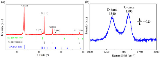
Figure 1.
Structural information on Ni@CNOs: (a) XRD pattern and (b) Raman spectra.
It can be seen that the degree of graphitization is calculated to be 58.7%, which also indicates the medium degree of graphitization for Ni@CNOs.
Figure 1b shows two strong Raman peaks of Ni@CNOs, corresponding to the disordered structure carbon (i.e., the D-band, 1340 cm−1) and graphite mode (i.e., the G-band, 1590 cm−1) with a ratio of ID/IG = 0.84, respectively. The structure of the sp2 hybridized carbon can be described by the G-band, and the intensity ratio between the G- toD-bands (i.e., IG/ID) can determine the extent of the graphite mode in carbon materials [36,37]. In addition, the presence of more porous disordered structures contributes to enhancing the diffusion of lithium-ion. The higher intensity of the G-band and the lower value of the ID/IG also confirm the medium degree of graphitization for Ni@CNOs. Figure S1 shows the XPS survey spectrum of Ni@CNOs, in which it can be seen that only C and O elements were detected on the material surface, and there was no Ni element. This is due to the thick carbon layer; the X-ray cannot penetrate the sample, so the Ni element cannot be detected in the XPS. In addition, different valence states of the C element in the composites can be seen in Figure 2e. The binding energies at 284.7, 285.9, and 288.1 eV are consistent with the Sp2 hybrid carbon (C-C), C-0 bond, and C=O bond, respectively.
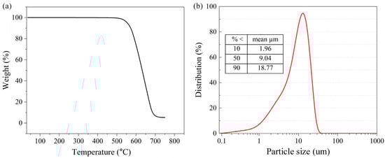
Figure 2.
(a) TGA image of Ni@CNOs and (b) particle size distribution of Ni@CNOs.
The thermal gravimetric analyzer (TGA) for the Ni@CNOs is shown in Figure 2a, where we recorded the relationship between the sample mass and the change in temperature. The Figure 2a samples have an obvious weight-loss range at T > 540 °C with a main weight loss of 90%. The remaining 10% of the residue should be NiO produced by the reaction of the nickel core and oxygen in the air. The results of the TGA analysis indirectly confirmed the prepared core–shell structure of the Ni@CNOs, which is consistent with the results obtained by SEM and TEM. Figure 2b shows the particle size distribution of Ni@CNOs. The average particle size of the samples is 9.04 um, which is bigger than the size from the observed SEM image; this test result is caused by the agglomeration of nanoparticles.
Figure 3a,b demonstrates the spherical morphologies of Ni@CNO powders in the SEM image, which are rich in irregularly shaped nanoparticles with a wide size distribution. Meanwhile, these spherical nanoparticles are agglomerated together to form carbon onion clusters due to intermolecular and electrostatic forces. The TEM image of the Ni@CNOs reveals a mostly shell/core structure, consisting of a crystalline core and a coating onion-like shell, as shown in Figure 3c,d. The diameter distribution of the nickel core is 30 to 150 nm and the thickness of the carbon shell is 40 to 80 nm. As can be seen from the HR-TEM image, the carbon structure is concentric with some degree of structural disorder, indicating multiple layers of fullerene-like carbon, as shown in Figure 3e. Ten to twenty graphitic layers are observed in the sample, with an average value of 0.34 nm for the interplanar distances (D-spacing) between the graphitic layers, corresponding to the (002) lattice plane of the graphite layers. Moreover, the selected area electron diffraction patterns (SAED) suggest the different diffraction spots of Ni@CNOs, including the graphitic layers (002) lattice plane and nickel (111) and (200) and (220) lattice plane, which is consistent with the results of the XRD patterns, as shown in Figure 3f. Apparently, nickel is a neutral metal atom in an onion-like shell, which means it is in a zero valence state. With these fullerene-like layers, the possibility for the infiltration of lithium-ion electrolytes greatly shortens the ion diffusion pathway in the Ni@CNOs anode. Carbon onion anode electronic conductivity may also be affected by the coalesced microstructure. Obviously, Ni nanoparticles are encapsulated in the onion-shaped graphite shell. In order to determine the content and distribution of elements on the surface of the CNO composite electrode material, we have carried out a spectroscopic analysis for the CNOs. The EDS pattern (Figure 3g–i) and the energy spectra (Figure S3) of the Ni@CNOs reveals the existence of nickel and carbon. Among them, the content of the C element (89.8 wt. %) is dominant, and the content of the Ni element (9.9 wt. %) is less, which corresponds to the peak value of Ni in the XRD test in Figure 3d, and their contents are consistent with the TGA test results.
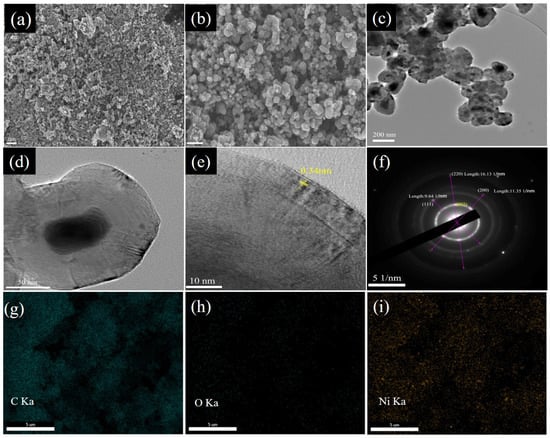
Figure 3.
SEM (a,b) images of Ni@CNOs. TEM (c,d) and HR-TEM (e) image of Ni@CNOs and (f) the corresponding SAED pattern. (g–i) SEM-EDS images.
Such structures provide good electrochemical stability and also increase the electrical conductivity of electrode materials. By comparing several common carbon materials on the market, as shown in Figure 4, Ni@CNOs show an electrical conductivity of 25.84 S cm−1 at 10 Mpa, which is higher than that of other carbon materials, such as commercial hard carbon (14.93 S cm−1), soft carbon (20.22 S cm−1), commercial graphite (18.65 S cm−1), and AC (2.56 S cm−1).
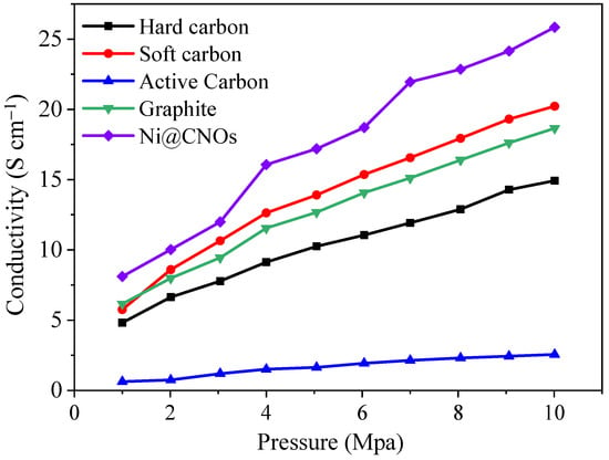
Figure 4.
Ni@CNOs and other carbon materials’ conductivity comparison.
As shown in Figure 5a, the BET specific surface area (surface area determined by the Brunauer–Emmett–Teller method) for Ni@CNOs is about 22.3 m2 g−1. The isotherm shape reveals an IV-type isotherm shape with a distinct hysteresis loop, which indicates that Ni@CNOs have porous structures. Furthermore, the pore size distribution calculated by the BJH method indicates that there is a pore size mode around 1.8 nm in Ni@CNOs, as shown in Figure 5b. Therefore, as anode electrodes for application in LICs, it is expected that Ni@CNOs can form a wide range of electrochemical reaction interfaces, while additional ion diffusion channels will reduce the interface resistance and enhance diffusion dynamics.
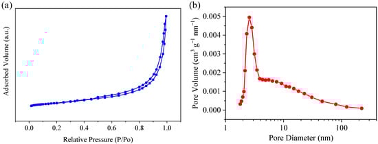
Figure 5.
Structural information of the Ni@CNOs. (a) N2 adsorption/desorption isotherms and (b) pore size distribution on the BJH model.
3.2. Electrochemical Performance of Ni@CNOs
Further investigations into the electrochemical performances of Ni@CNOs were evaluated within the potential window of 0.01–3.0 V vs. Li/Li+. Figure 6a presents the cyclic voltammetry (CV) profile of the Ni@CNOs electrode at a scan rate of 0.1 mV s−1. A pair of obvious redox peaks were observed in the range of 0.001–0.3 V and a pair of weak broad peaks were observed in 0.8–1.3 V. The obvious redox peaks are attributed to lithium intercalation/de-intercalation and the weak broad peaks are caused by edge adsorption and surface adsorption [38]. In addition, an additional peak located at around 0.6 V is attributed to the formation of SEI. There is no redox pair of nickel in the CV curve, so Ni plays a role in improving the conductivity of materials in Ni@CNOs [39,40]. The energy consumed in the SEI film process leads to an initial irreversible capacity. According to Figure 6b, the initial discharge and charge capacities were 869 and 481 mAh g−1 at 0.1 A g−1, respectively. From the result, the initial coulomb efficiency of the Ni@CNOs electrode is about 55.35%, which can be attributed to the solid electrolyte interface (SEI) film. The subsequent charging and discharging process was stabilized with a capacity of 480 mAh g−1 and a coulomb efficiency of almost 100%.
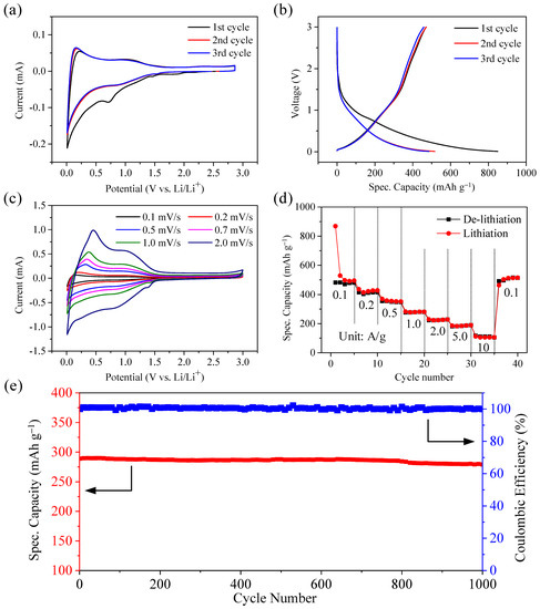
Figure 6.
Electrochemical properties of the Ni@CNOs anode. (a) CV curves of the Ni@CNOs anode, (b) initial three charge/discharge cycles of the Ni@CNOs anode, (c) CV curves at scan rates of 0.1 to 10 mV s−1, (d) specific capacities of the Ni@CNOs anode at different current densities, and (e) the cycling performance and its corresponding coulombic efficiency at a current density of 1 A g−1.
Figure 6c depicts the CV curves of Ni@CNOs at scan rates of 0.1 to 2.0 mV s−1. It can be seen that the sharp reduction peak appeared at the potentials of 0.75 V during the first cycle, which is generally ascribed to the formation of solid electrolyte interface (SEI) film on the Ni@CNOs surface. After the second circle, the peak becomes stable; it is gleamingly obvious that there are a pair of obvious redox peaks in the range of 0.001–0.3 V and a pair of weak broad peaks in 0.8–1.3 V. The obvious redox peaks are attributed to the lithium intercalation/de-intercalation and the weak broad peaks are caused by edge adsorption and surface adsorption. As shown in Figure 6d, the reversible specific capacity of the Ni@CNOs anode at 0.1 A g−1 is 480 mAh g−1. Moreover, when the current density was increased to 2 A g−1, the reversible specific capacity of the Ni@CNOs anode remained at 242 mAh g−1 and especially when the current density was increased to 10 A g−1, the reversible specific capacity of the Ni@CNOs anode remained at 111 mAh g−1. The reversible specific capacity reached its initial value when the C-rate returned to 0.1 A g−1 after high-speed measurements, implying stable electrochemical performance of the Ni@CNOs anode. Thus, in general, because of the additional interface area and pore structure of the graphene in the Ni@CNOs composite, reaction kinetics and ion transfer can be greatly improved. In addition, the presence of metal Ni increases the electronic conductivity of the Ni@CNOs anode. In addition, the cycling stability of the Ni@CNOs at a high current density has also been investigated. As shown in Figure 6e, the Ni@CNOs exhibit an outstanding capacity retention of 96.5% at 1 A g−1 and a coulombic efficiency approaching 100% after 1000 cycles in the half-cells. As a result of incomplete activation of the anode, the specific capacity first decreased and then gradually increased [41]. After about 1000 cycles, the device operated stably, which can be owed to the highly stable SEI film formed on the Ni@CNO surface.
3.3. Performance of LIC Pouch Cells Based on an Ni@CNO Anode and AC (Activated Carbon) Cathode
To deal with the low coulomb efficiency of the Ni@CNO anode materials in the first cycle and to reduce the influence of the electrolyte ion concentration on device performance during the formation of SEI film, the anode Ni@CNOs material was pre-embedded with lithium and assembled into a complete battery with AC cathode material. The pre-lithiation process of the anode is typically utilized, and therefore the working voltage window can be enlarged to boost the energy density [42,43]. According to the conservation of electric quantity, the maximum capacity that can be released by the energy storage device is mainly determined by the cathode material. However, at the same time, the surface load of the pole plate cannot expand infinitely. In the actual operation process, excessively thick electrode plates are prone to powder dropping, which does not adhere well to the collector and also affects the conductivity of the electrode plate. Therefore, in order to maximize the material capacity, the energy density and power density were balanced. Then, the LIC pouch cells were assembled with three mass ratios of 1:1, 1:2, and 1:3 (anode vs. cathode) and the electrochemical performance was measured to determine the optimal ratio of the anode and cathode.
Galvanostatic cycling of AC//Ni@CNOs LIC pouch cell systems at current densities of 0.1 A g−1 to 10 A g−1 was conducted to evaluate their rate performance. As shown in Figure 7a, LIC pouch cells with a mass ratio of 2:1 provided highly specific capacities of 78.48, 75.42, 70.38, 66.96, 61.92, and 55.26 F g−1 at 0.1, 0.2, 1, 2, 5, and 10 A g−1, respectively, within a potential range of 2.0–4.2 V, which is much better than the other two LIC pouch cells. Based on the above experimental results, the optimized cathode/anode mass ratio of AC [activated carbon (YP-80)]//Ni@CNOs LIC pouch cells is 2:1. Figure 7b shows the CV curves of the LIC pouch cells at various scan rates from 2 to 20 mV s−1 in the voltage range of 2.0–4.2 V. As expected, the LIC pouch cells display a rectangular shape, and no apparent shape distortion was observed at a scan rate of 20 mV s−1, indicating good capacitance behavior. Figure 7c shows the linear and symmetric voltage profiles of the AC [activated carbon (YP-80)]//Ni@CNOs (the mass ratio of 2:1) LIC pouch cells within the voltage range of 2.0–4.2 V, which clearly demonstrates its excellent capacitive behavior. This result is again consistent with the CV measurements. Figure 7d reveals a comparison of the rate capability of AC//Ni@CNOs LIC pouch cells and pure AC//SC LIC pouch cells in the voltage range of 2.0–4.2 V, with the rate performance of the AC//Ni@CNOs LIC pouch cells being much better than that of the AC//SC LIC pouch cells at current densities from 0.1 to 10 A g−1. This excellent electrochemical performance can be ascribed to the special structure of Ni@CNOs. For the EIS analysis, EIS was employed to further explore the electrochemical behavior of the LIC pouch cells. Figure 6e displays the Nyquist plot for the LIC pouch cells device. In the corresponding equivalent circuit model, Rs represents the e ohmic internal resistance, Rct is the charge transfer resistance, and Cdl denotes the double-layer capacitance and capacity of the surface layer. The ohmic internal resistance and charge transfer internal resistance of the capacitor are very small, which is attributed to the coalescence and interparticle connectivity of the Ni@CNOs. According to the Nyquist plot, the Rct value of SC is greater than Ni@CNOs. This result reveals that the reaction resistance is decreased by the additional interface area provided by the Ni@CNOs network in the composite. Figure 7f shows the long-term high rate cycling of the AC (activated carbon (YP-80))//Ni@CNOs LIC pouch cells cell at a rate of 2 A g−1 in the voltage range of 2.2–3.8 V. After a further 40,000 cycles, the LIC pouch cells maintain good cycle ability, with 94.09% capacity retention and a coulombic efficiency close to 100% at full cycling. The result clearly demonstrates the superior rate capability of the AC [activated carbon (YP-80)]//Ni@CNOs system, which indicates that the Ni@CNOs anode remains stable with cyclic stability against cycling, without li+ consumption and particle pulverization.
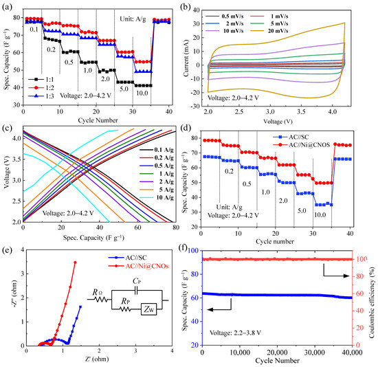
Figure 7.
Electrochemical properties of the LIC pouch cells. (a) Rate performance of three LIC pouch cells with various mass ratios (anode vs. cathode) (b) CV curves of the LIC pouch cells with different scan rates in the voltage range of 2.0–4.2 V, (c) charge and discharge profiles of LIC from 0.1 to10 A g−1 in the voltage range of 2.0–4.2 V, (d) comparison of rate capability of the AC//Ni@CNOs LIC pouch cells and the pure AC//SC LIC pouch cells, (e) Nyquist plot of the LIC, and (f) long-term high-rate cycling performance at 2 A g−1 in the LIC pouch cells in the voltage range of 2.2–3.8 V.
The porous structure of Ni@CNOs increases the electrode reaction interface, thus providing more favorable ion diffusion channels and a wider range of electrochemical reaction interfaces. Ultimately this reduces the interface reaction impedance and internal resistance caused by concentration polarization. Specifically, the presence of Ni in CNOs increases the electronic conductivity of the electrode and improves the multiplier performance of the device.
Figure 8 shows the gravimetric Ragone plot of the AC [activated carbon (YP-80)]//Ni@CNOs and the LIC pouch cells reported in the reference. As expected, the AC//Ni@CNOsLIC pouch cells reach an energy density of up to 140.1 Wh Kg−1 at 275 W kg−1. Even at an ultra-high power density of 27 kW kg−1, the electrode can deliver an energy density of 76.6 Wh kg−1. Compared to several representative LIC pouch cells systems, our AC [activated carbon (YP-80)]//Ni@CNOsLIC pouch cells exhibit superior energy and power performance, such as nitrogen-enriched mesoporous carbon nanospheres/graphene (N-GMCS)//pre-lithiated microcrystalline graphite (PLMG) [44], URGO (urea (H2N-CO-NH2) RGO)//AC (commercial products) [45], HC (commercial products)//AC (commercial products) [46], and HC (commercial products)//AC (commercial products) [47], with more detailed information provided in Table 1. From the above discussions, this study offers a promising platform for the Ni@CNOs anodes as prospective electrode materials for electrochemical energy storage applications.
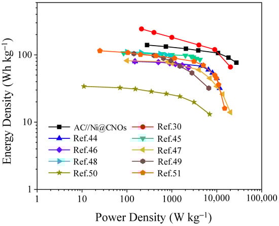
Figure 8.
Ragone plots comparison of AC//Ni@CNOs with other recently reported LIC pouch cells systems (based on the mass of electrode materials).

Table 1.
Literature comparison showing several reported LIC systems with carbonaceous anodes.
4. Conclusions
In this work, the effects of Ni@CNOs as pre-lithiated anode materials on the electrochemical performances of LICs were investigated. Due to their large specific surface area, high conductivity, and the presence of metal Ni increasing the electronic conductivity, Ni@CNOs exhibit excellent electron and ion transport for rapid electrochemical interactions with Li+ and a significant improvement in the rate performance of LICs. For the Ni@CNOs as anodes vs. Li/Li+, when the current density was increased to 20 A g−1, the reversible specific capacity remained at 111 mAh g−1. Furthermore, pouch-type AC//Ni@CNOs LICs with a high energy density and a high-power density were successfully fabricated. According to the experimental results, the AC//Ni@CNOs LIC achieves an energy density of up to 140.1 Wh Kg−1 at a power density of 275 W kg−1. Even more, at an ultra-high power density of 27 kW kg−1, the electrode can deliver an energy density of 76.6 Wh kg−1, which is superior to the energy density of carbonaceous anodes and the power density of commercial supercapacitors. These capacitors also demonstrate excellent cycling stability, with a 94.09% capacitance retention over 40,000 cycles. Hence, the Ni@CNOs demonstrate potential for application in practical LICs. In future work, Ni will be removed from the CNOs, and then the pure CNOs’ electrochemical performance and their application in the field of LICs will be tested.
Supplementary Materials
The following supporting information can be downloaded at: https://www.mdpi.com/article/10.3390/batteries9020102/s1, Table S1. The productivity of CNOs synthesized at different temperatures; Table S2. The productivity of CNOs synthesized with different flows; Figure S1. (a) The XPS survey spectrum and (b) high-resolution XPS spectrum of the C 1 s region in Ni@CNOs; Figure S2. TEM image of Ni@CNOs; Figure S3. The energy spectra of Ni@CNOs.
Author Contributions
Conceptualization, X.Z. (Xiaohu Zhang), X.Z. (Xiong Zhang) and Y.M.; methodology, X.Z. (Xiong Zhang), K.Z., W.Z., X.Z. (Xiaohu Zhang) and Y.M.; software, X.Z. (Xiaohu Zhang), K.Z. and X.Z. (Xiong Zhang); validation, X.Z. (Xiong Zhang), X.Z. (Xiaohu Zhang), K.W. and Y.M.; formal analysis, X.Z. (Xiaohu Zhang) and X.Z. (Xiong Zhang); investigation, X.Z. (Xiong Zhang), K.Z. and C.L.; resources, X.Z. (Xiong Zhang) and Y.M.; data curation, X.Z. (Xiong Zhang), K.Z., L.W., X.S., Y.A. and X.Z. (Xiaohu Zhang); writing—original draft preparation, X.Z. (Xiong Zhang), K.Z., W.Z. and X.Z. (Xiaohu Zhang); writing—review and editing, X.Z. (Xiong Zhang), K.Z., W.Z. and X.Z. (Xiaohu Zhang); visualization, X.Z. (Xiong Zhang), K.Z., W.Z. and X.Z. (Xiaohu Zhang); supervision, X.S., K.W. and Y.M.; project administration, X.Z. (Xiaohu Zhang), X.Z. (Xiong Zhang) and Y.M.; funding acquisition, X.Z. (Xiong Zhang) and Y.M. All authors have read and agreed to the published version of the manuscript.
Funding
This research was funded by the National Natural Science Foundation of China, grant numbers 52077207, 51822706, and 51777200, Beijing Natural Science Foundation, grant number JQ19012, and the Dalian National Laboratory for Clean Energy (DNL) Cooperation Fund, CAS grant numbers DNL201912 and DNL201915.
Institutional Review Board Statement
Not applicable.
Informed Consent Statement
Not applicable.
Data Availability Statement
Not applicable.
Conflicts of Interest
The authors declare no conflict of interest.
References
- Dunn, B.; Kamath, H.; Tarascon, J.-M. Electrical energy storage for the grid: A battery of choices. Science 2011, 334, 928–935. [Google Scholar] [CrossRef]
- Simon, P.; Gogotsi, Y. Perspectives for electrochemical capacitors and related devices. Nat. Mater. 2020, 19, 1151–1163. [Google Scholar] [CrossRef] [PubMed]
- Zuo, W.; Li, R.; Zhou, C.; Li, Y.; Xia, J.; Liu, J. Battery-supercapacitor hybrid devices: Recent progress and future prospects. Adv. Sci. 2017, 4, 1600539. [Google Scholar] [CrossRef] [PubMed]
- Sun, Y.; Liu, N.; Cui, Y. Promises and challenges of nanomaterials for lithium-based rechargeable batteries. Nat. Energy 2016, 1, 16071. [Google Scholar] [CrossRef]
- Ock, I.W.; Lee, J.; Kang, J.K. Metal-organic framework-derived anode and polyaniline chain networked cathode with mesoporous and conductive pathways for high energy density, ultrafast rechargeable, and long-life hybrid capacitors. Adv. Energy Mater. 2020, 10, 2001851. [Google Scholar] [CrossRef]
- Xu, J.; Gao, B.; Huo, K.F.; Chu, P.K. Recent progress in electrode materials for nonaqueous lithium-ion capacitors. J. Nanosci. Nanotechnol. 2020, 20, 2652–2667. [Google Scholar] [CrossRef]
- Zheng, J.P. Theoretical energy density for electrochemical capacitors with intercalation electrodes. J. Electrochem. Soc. 2005, 152, A1864–A1869. [Google Scholar] [CrossRef]
- Wang, H.W.; Zhu, C.R.; Chao, D.L.; Yan, Q.Y.; Fan, H.J. Nonaqueous hybrid lithium-ion and sodium-ion capacitors. Adv. Mater. 2017, 29, 1702093. [Google Scholar] [CrossRef]
- Karimi, D.; Behi, H.; Van Mierlo, J.; Berecibar, M. A comprehensive review of lithium-ion capacitor technology: Theory, development, modeling, thermal management systems, and applications. Molecules 2022, 27, 3119. [Google Scholar] [CrossRef]
- Ma, Y.F.; Chang, H.C.; Zhang, M.; Chen, Y.S. Graphene-based materials for lithium-ion hybrid supercapacitors. Adv. Mater. 2015, 27, 5296–5308. [Google Scholar]
- Zhang, X.H.; Sun, X.Z.; An, Y.B.; Zhang, X.; Li, C.; Zhang, K.L.; Song, S.; Wang, K.; Ma, Y.W. Design of a fast-charge lithium-ion capacitor pack for automated guided vehicle. J. Energy Storage 2022, 48, 104045. [Google Scholar] [CrossRef]
- Omonayo, B.; Annadanesh, S.; Zheng, J.P. Lithium-ion capacitor safety testing for commercial application. Batteries 2019, 5, 74. [Google Scholar]
- Barcellona, S.; Ciccarelli, F.; Iannuzzi, D.; Piegari, L. Overview of lithium-ion capacitor applications based on experimental performances. Electr. Power Compon. Syst. 2016, 44, 1248–1260. [Google Scholar] [CrossRef]
- Liu, W.J.; Zhang, X.; Xu, Y.N.; Li, C.; Wang, K.; Sun, X.Z.; Su, F.Y.; Chen, C.M.; Liu, F.Y.; Wu, Z.S.; et al. Recent advances of carbon-based materials for high performance lithium-ion capacitors. Batter. Supercaps 2021, 4, 407–428. [Google Scholar] [CrossRef]
- Wang, Q.; Jiang, X.; Tong, Q.; Li, H.; Li, J.; Yang, W. Continuously interconnected N-doped porous carbon for high-performance lithium-ion capacitors. Nanoenergy Adv. 2022, 2, 303–315. [Google Scholar] [CrossRef]
- Wang, Q.; Liu, F.; Jin, Z.; Qiao, X.; Huang, H.; Chu, X.; Xiong, D.; Zhang, H.; Liu, Y.; Yang, W. Hierarchically divacancy defect building dual-activated porous carbon fibers for high-performance energy-storage devices. Adv. Funct. Mater. 2020, 30, 2002580. [Google Scholar] [CrossRef]
- Banerjee, A.; Upadhyay, K.K.; Puthusseri, D.; Aravindan, V.; Madhavi, S.; Ogale, S. MOF-derived crumpled-sheet-assembled perforated carbon cuboids as highly effective cathode active materials for ultra-high energy density Li-ion hybrid. Nanoscale 2014, 6, 4387–4394. [Google Scholar] [CrossRef]
- Stoller, M.D.; Murali, S.; Quarles, N.; Zhu, Y.; Potts, J.R.; Zhu, X.; Ha, H.W.; Ruoff, R.S. Activated graphene as a cathode material for Li-ion hybrid supercapacitors. Phys. Chem. Chem. Phys. 2012, 14, 3388–3391. [Google Scholar] [CrossRef]
- Lee, J.H.; Shin, W.H.; Lim, S.Y.; Kim, B.G.; Choi, J.W. Modified graphite and graphene electrodes for high-performance lithium ion hybrid capacitors. Mater. Renew. Sustain. Energy 2014, 3, 22. [Google Scholar] [CrossRef]
- Yi, S.; Wang, L.; Zhang, X.; Li, C.; Liu, W.J.; Wang, K.; Sun, X.Z.; Xu, Y.N.; Yang, Z.X.; Cao, Y.S.; et al. Cationic intermediates assisted self-assembly two-dimensional Ti3C2Tx/rGO hybrid nanoflakes for advanced lithium-ion capacitors. Sci. Bull. 2021, 66, 914. [Google Scholar] [CrossRef]
- Zeiger, M.; Jäckel, N.; Mochalin, V.N.; Presser, V. Review: Carbon onions for electrochemical energy storage. J. Mater. Chem. A 2016, 4, 3172–3196. [Google Scholar] [CrossRef]
- Dhand, V.; Yadav, M.; Kim, S.H.; Rhee, K.Y. A comprehensive review on the prospects of multi-functional carbon nano onions as an effective, high- performance energy storage material. Carbon 2021, 175, 534–575. [Google Scholar] [CrossRef]
- Tan, Z.-L.; Wei, J.-X.; Liu, Y.; Zaman, F.U.; Rehman, W.; Hou, L.-R.; Yuan, C.-Z. V2CTx MXene and its derivatives: Synthesis and recent progress in electrochemical energy storage applications. Rare Metals 2022, 41, 775. [Google Scholar] [CrossRef]
- Sun, X.Z.; Geng, L.B.; Yi, S.; Li, C.; An, Y.B.; Zhang, X.H.; Zhang, X.; Wang, K.; Ma, Y.W. Effects of carbon black on the electrochemical performances of SiOx anode for lithium-ion capacitors. J. Power Source 2021, 499, 229936. [Google Scholar] [CrossRef]
- Akintola, T.; Shellikeri, A.; Akintola, T.; Zheng, J.P. The influence of Li4Ti5O12 preparation method on lithium-ion capacitor performance. Batteries 2021, 7, 33. [Google Scholar] [CrossRef]
- An, Y.B.; Liu, T.Y.; Li, C.; Zhang, X.; Hu, T.; Sun, X.Z.; Wang, K.; Wang, C.D.; Ma, Y.W. A general route for the mass production of graphene-enhanced carbon composites toward practical pouch lithium-ion capacitors. J. Mater. Chem. A 2021, 9, 15654. [Google Scholar] [CrossRef]
- Portet, C.; Yushin, G.; Gogotsi, Y. Electrochemical performance of carbon onions, nanodiamonds, carbon black and multiwalled nanotube in electrical double layer capacitors. Carbon 2007, 45, 2511–2518. [Google Scholar] [CrossRef]
- Chen, J.; Yang, B.; Li, H.; Ma, P.; Lang, J.; Yan, X. Candle soot: Onion-like carbon, an advanced anode material for a potassium-ion hybrid capacitor. J. Mater. Chem. A 2019, 7, 9247–9252. [Google Scholar] [CrossRef]
- Jäckel, N.; Weingarth, D.; Zeiger, M.; Aslan, M.; Grobelsek, I.; Presser, V. Comparison of carbon onions and carbon blacks as conductive additives for carbon supercapacitors in organic electrolytes. J. Power Source 2014, 272, 1122–1133. [Google Scholar] [CrossRef]
- Shi, K.Y.; Liu, J.W.; Chen, R. Nitrogen-Doped nano-carbon onion rings for energy storage in Lithium-ion capacitors. J. Energy Storage 2020, 31, 101609. [Google Scholar] [CrossRef]
- Permana, A.D.C.; Ding, L.; Gonzalez-Martinez, I.G.; Hantusch, M.; Nielsch, K.; Mikhailova, D.; Omar, A. Comparative study of onion-like carbons prepared from different synthesis routes towards li-ion capacitor application. Batteries 2022, 8, 160. [Google Scholar] [CrossRef]
- Permana, A.D.C.; Omar, A.; Gonzalez-Martinez, L.G.; Oswald, S.; Giebeler, L.; Nielsch, K.; Mikhailova, D. MOF-derived onion-like carbon with superior surface area and porosity for high performance lithium-ion capacitors. Batter. Supercaps 2022, 5, e202100353. [Google Scholar]
- Aref, A.R.; Chen, S.W.; Rajagopalan, R.; Randall, C. Bimodal porous carbon cathode and prelithiated coalesced carbon onion anode for ultrahigh power energy efficient lithium ion capacitors. Carbon 2019, 152, 89–97. [Google Scholar] [CrossRef]
- Zhang, L.; Zhou, Q.; Zhao, H.T.; Ruan, C.; Wang, Y.J.; Li, Z.J.; Lian, Y.F. The arc-discharged Ni-cored carbon onions with enhanced microwave absorption performances. Mater. Lett. 2020, 265, 127408. [Google Scholar] [CrossRef]
- Hechmann, A.; Fromm, O.; Rodehorst, U.; Münster, P.; Winter, M.; Placke, T. New Insights into Electrochemical Anion Intercalation into Carbonaceous Materials for Dual-Ion Batteries: Impact of Graphitization Degree. Carbon 2018, 131, 201–212. [Google Scholar] [CrossRef]
- Ma, Y.; Wang, K.; Xu, N.Y.; Zhang, D.X.; Peng, F.Q.; Li, N.S.; Zhang, X.; Sun, Z.X.; Ma, W.Y. Dehalogenation produces graphene wrapped carbon cages as fast-kinetics and large-capacity anode for lithium-ion capacitors. Carbon 2023, 202, 175–185. [Google Scholar] [CrossRef]
- Li, C.; Zhang, X.; Wang, K.; Sun, Z.X.; Ma, W.Y. High-power and long-life lithium-ion capacitors constructed from N-doped hierarchical carbon nanolayer cathode and mesoporous graphene anode. Carbon 2018, 140, 237–248. [Google Scholar] [CrossRef]
- Chen, C.J.; Wang, Z.G.; Miao, L.; Cai, J.; Peng, L.F.; Huang, Y.Y.; Zhang, L.N.; Xie, J. Nitrogen-rich hard carbon as a highly durable anode for high-power potassium-ion batteries. Energy Storage Mater. 2017, 8, 161–168. [Google Scholar] [CrossRef]
- Yue, Y.; Juarez-Robles, D.; Mukherjee, P.; Liang, H. Superhierarchical Nickel–Vanadia Nanocomposites for Lithium Storage. ACS Appl. Energy Mater. 2018, 1, 2056–2066. [Google Scholar] [CrossRef]
- Chen, Y.; Chen, H.Y.; Du, F.H.; Shen, X.P.; Ji, Z.Y.; Zhou, H.B.; Yuan, A.H. In-situ construction of nano-sized Ni-NiO-MoO2 heterostructures on holey reduced graphene oxide nanosheets as high-capacity lithium-ion battery anodes. J. Alloys Compd. 2022, 926, 166847. [Google Scholar] [CrossRef]
- Jin, L.M.; Guo, X.; Shen, C.; Qin, N.; Zheng, J.S.; Wu, Q.; Zhang, C.M.; Zheng, J.P. A universal matching approach for high power-density and high cycling-stability lithium ion capacitor. J. Power Source 2019, 441, 227211. [Google Scholar] [CrossRef]
- Naderi, R.; Shellikeri, A.; Hagen, M.; Cao, W.; Zheng, J.P. The influence of anode/cathode capacity ratio on cycle life and potential variations of lithium-ion capacitors. J. Electrochem. Soc. 2019, 166, A2610–A2617. [Google Scholar] [CrossRef]
- Yu, X.L.; Zhan, C.Z.; Lv, R.T.; Bai, Y.; Lin, Y.X.; Huang, Z.H.; Shen, W.C.; Qiu, X.P.; Kang, F.Y. Ultrahigh-rate and high-density lithium-ion capacitors through hybriding nitrogen-enriched hierarchical porous carbon cathode with prelithiated microcrystalline graphite anode. Nano Energy 2015, 5, 43–53. [Google Scholar] [CrossRef]
- Lee, J.H.; Shin, W.H.; Ryon, M.H.; Jin, J.K.; Kim, J.Y.; Choi, J.W. Functionalized graphene for high performance lithium ion capacitors. ChemSusChem 2012, 5, 2328–2333. [Google Scholar] [CrossRef] [PubMed]
- Kim, J.H.; Kin, J.S.; Lim, Y.G.; Lee, J.G.; Kim, Y.J. Effect of carbon types on the electrochemical properties of negative electrodes for Li-ion capacitors. J. Power Source 2011, 196, 10490–10495. [Google Scholar] [CrossRef]
- Cao, W.J.; Zheng, J.P. Li-ion capacitors with carbon cathode and hard carbon/stabilized lithium metal powder anode electrodes. J. Power Source 2012, 213, 180–185. [Google Scholar] [CrossRef]
- Du, H.P.; Yang, H.; Huang, C.S.; He, J.J.; Liu, H.B.; Li, Y.L. Graphdiyne applied for lithium-ion capacitors displaying high power and energy densities. Nano Energy 2016, 22, 615–622. [Google Scholar] [CrossRef]
- Yang, Z.W.; Guo, H.J.; Li, X.H.; Wang, Z.X.; Wang, J.X.; Wang, Y.S.; Yan, Z.L.; Zhang, D.C. Graphitic carbon balanced between high plateau capacity and high rate capability for lithium ion capacitors. J. Mater. Chem. A 2017, 5, 15302–15309. [Google Scholar] [CrossRef]
- Han, X.Q.; Han, P.X.; Yao, J.H.; Zhang, S.; Cao, X.Y.; Xiong, J.W.; Zhang, J.N.; Cui, G.L. Nitrogen-doped carbonized polyimide microsphere as a novel anode material for high performance lithium-ion capacitors. Electrochim. Acta 2016, 196, 603–610. [Google Scholar] [CrossRef]
- Schroeder, M.; Winter, M.; Passerini, S.; Balducci, A. On the cycling stability of lithium-ion capacitors containing soft carbon as anodic material. J. Power Source 2013, 238, 388–394. [Google Scholar] [CrossRef]
- Ren, J.J.; Su, L.W.; Qin, X.; Yang, M.; Wei, J.P.; Zhou, Z.; Shen, P.W. Pre-lithiated graphene nanosheets as negative electrode materials for Li-ion capacitors with high power and energy density. J. Power Source 2014, 264, 108–113. [Google Scholar] [CrossRef]
Disclaimer/Publisher’s Note: The statements, opinions and data contained in all publications are solely those of the individual author(s) and contributor(s) and not of MDPI and/or the editor(s). MDPI and/or the editor(s) disclaim responsibility for any injury to people or property resulting from any ideas, methods, instructions or products referred to in the content. |
© 2023 by the authors. Licensee MDPI, Basel, Switzerland. This article is an open access article distributed under the terms and conditions of the Creative Commons Attribution (CC BY) license (https://creativecommons.org/licenses/by/4.0/).