Article

PEI/Super P Cathode Coating: A Pathway to Superior Lithium–Sulfur Battery Performance

1
Department of Hydrogen & Renewable Energy, Kyungpook National University, Daegu 41566, Republic of Korea
2
Department of Applied Chemistry, Kyungpook National University, Daegu 41566, Republic of Korea
3
School of Integrative Engineering, Chung-Ang University, 84, Heukseok-ro, Dongjak-Gu, Seoul 06974, Republic of Korea
4
Department of Chemical and Biomolecular Engineering, Korea Advanced Institute of Science and Technology (KAIST), 291 Daehak-ro, Yuseong-gu, Daejeon 34141, Republic of Korea
*
Authors to whom correspondence should be addressed.
Batteries 2023, 9(11), 531; https://doi.org/10.3390/batteries9110531
Submission received: 18 September 2023 / Revised: 18 October 2023 / Accepted: 23 October 2023 / Published: 25 October 2023
(This article belongs to the Special Issue Designing High-Energy Lithium-Sulfur Batteries)

Abstract

:
Lithium–sulfur batteries exhibit a high energy density of 2500–2600 Wh/kg with affordability and environmental advantages, positioning them as a promising next-generation energy source. However, the insulating nature of sulfur/Li2S and the rapid capacity fading due to the shuttle effect have hindered their commercialization. In this study, we propose a method to boost the performance of lithium–sulfur batteries by modifying the sulfur cathode with a coating layer composed of polyethyleneimine (PEI) and Super P conductive carbon. The PEI/Super P-modified electrode retained 73% of its discharge capacity after 300 cycles at the 2 C scan rate. The PEI/Super P coated layer effectively adsorbs lithium polysulfides, suppressing the shuttle effect and acting as an auxiliary electrode to facilitate the electrochemical reactions of sulfur/Li2S. We analyzed the PEI/Super P-modified electrodes using symmetric cells, electrochemical impedance spectroscopy, and cyclic voltammetry. The battery manufacturing method presented here is not only cost-effective but also industrially viable due to its compatibility with the roll-to-roll process.

Graphical Abstract

1. Introduction

In the light of diminishing fossil fuel reserves and growing global concerns about greenhouse gas-induced climate change, lithium-ion batteries (LIBs) have emerged as a prominent sustainable energy alternative [1,2,3]. With the consistent rise in energy demands, research on LIBs has surged, leading to continuous enhancements in their performance. Yet, as the currently commercialized lithium-ion electrodes, which rely on intercalation, approach their theoretical storage capacity limits, there is a growing interest in exploring novel materials for the energy solutions of the future. In this context, lithium–sulfur (Li–S) batteries are garnering attention. They offer considerable advantages, including abundant resources, an impressive theoretical capacity of 1675 mAh/g and an energy density of 2500–2600 Wh/kg, which outperforms currently commercialized batteries [4,5].
While Li–S batteries offer numerous advantages, several challenges hinder their commercialization. First, the sulfur particles and Li2S produced during charging/discharging possess poor electronic/ionic conductivity, leading to an increase in the internal resistance of the cathode. Second, the roughly 80% volume change of sulfur particles during charge and discharge cycles exacerbates structural instability within the battery cell, adversely impacting its performance. Finally, lithium polysulfides (LiPSs, Li2Sn, n ≥ 4), which form during sulfur lithiation, dissolve in the electrolyte and migrate towards the anode. This causes a ‘shuttle effect’, significantly diminishing Coulombic efficiency and capacity. The shuttle effect, in particular, greatly accelerates the degradation of Li–S batteries, leading to a drastically reduced lifespan and posing challenges for commercialization. As such, these issues remain as obstacles that must be addressed for Li–S batteries to realize their potential as next-generation energy sources [6].
Numerous studies have been undertaken to enhance the performance of Li–S batteries. To address the aforementioned issues, several strategies have been proposed to immobilize the polysulfides formed during cycling within the cathode. Conductive porous structures like carbon nanotubes (CNTs), graphene, and mesoporous carbon can physically confine the active material, suppressing polysulfide diffusion and enhancing electronic conductivity [7,8,9,10,11,12,13,14,15]. Moreover, studies have reported that metal oxides such as TiO2, Ti4O7, MnO2 and metal sulfides like Co3S4 and MoS2 can strongly adsorb polysulfides on their surface. These materials also act as catalysts to promote electrochemical reactions, effectively mitigating the shuttle effect [16,17,18,19,20,21]. Despite advancements in polysulfide research, the challenges posed by inherent sulfur properties in Li–S batteries remain unresolved, necessitating further investigation. Furthermore, the use of high-cost materials and manufacturing techniques not only diminishes the economic viability of Li–S batteries but also hinders their path to commercialization. Thus, research that considers scalability and mass production is imperative.
Su and Manthiram introduced a conductive interlayer between the cathode and the separator to enhance the performance of Li–S batteries [22,23]. This interlayer serves as an auxiliary cathode, curbing LiPSs migration, which in turn optimizes sulfur utilization and enhances electrical conductivity. Notably, carbon-based materials such as graphene oxide and CNTs, known for their effectiveness in Li–S batteries, have been crucial in mitigating the shuttle effect [24,25,26,27].
Recently, several studies have demonstrated that a direct coating on sulfur electrodes improves cycling performance. By depositing a thin organic or inorganic coating on the electrode surface, the dissolution and loss of active sulfur caused by LiPSs is significantly reduced due to the strong adsorption of LiPSs onto the coated layers. These materials significantly enhance the performance of Li–S batteries by effectively controlling the shuttle effect and preserving high capacity during rapid charge and discharge cycles [28,29,30,31,32,33]. Many studies have pursued the commercialization of Li–S batteries, but practical advancements remain challenging due to the high cost and complex processing of materials used to mitigate the shuttle effect. Therefore, it is crucial to develop low-cost, thin materials that maintain electronic conductivity and energy density, while also offering strong polysulfide adsorption and excellent cycle stability [34].
In this study, we combined polyethyleneimine (PEI) with Super P to create a thin PEI/Super P-modified sulfur cathode (PEI/Super P/S) as shown in Scheme 1. We utilized Super P, a commercially available carbon black widely used in the Li-ion battery field, as the coating layer material for the purpose of manufacturing Li–S batteries [35,36]. The branched structure of PEI is rich in amine groups that form strong dipole–dipole electrostatic interactions with LiPSs. These interactions effectively anchor polysulfides to the cathode, reducing the shuttle effect [37,38]. Furthermore, the hydrophilic nature of PEI improves the wettability of the polar electrolyte on the hydrophobic surface of Super P particles. The hydrophilic nature of the electrode surface is known to increase the Li+ ion diffusion rate and enhance contact with polar LiPSs [30,39,40]. Li–S batteries modified with PEI/Super P sustained a reversible capacity of 575 mAh/g after 300 cycles at a high current density of 2 C, outperforming conventional electrodes. These benefits can be achieved with commercially available, low-cost materials without the need for expensive and intricate processes, providing significant advantages for the large-scale production and commercialization of Li–S batteries

2. Materials and Methods

2.1. Materials

Polyethyleneimine (PEI, ~25,000 Mw, branched, Sigma–Aldrich, Seoul, Republic of Korea), Super P (Imerys Graphite & Carbon Belgium SA), sulfur (S, 99.5%, Alfa Aesar, orthorhombic α-sulfur), lithium sulfide (Li2S, 99.98%, Sigma-Aldrich), poly(vinylidene fluoride) (PVDF, 99%; Alfa Aesar), N-methyl-2-pyrrolidone (NMP, 99.5%, Sigma-Aldrich), isopropyl alcohol (IPA, 99.5%, Duksan Pure Chemicals, Ansan, Republic of Korea), 1,2-dimethoxyethane (DME, 99.0%, Samchun Pure Chemical, Seoul, Republic of Korea), dioxolane (DOL, 99.5%, Alfa Aesar, Seoul, Republic of Korea), lithium nitrate (LiNO3, 99.99%, Sigma-Aldrich) and 1 M bistrifluoromethane sulfonamide lithium salt (LiTFSI) dissolved in a 1:1 volume ratio of DME and DOL (PANAX ETEC, Republic of Korea) were used as received, without further purification. Super P was annealed for 3 h at 700 °C in a 5% H2/Ar atmosphere prior to use to remove any moisture that might have been adsorbed on the surface and to eliminate any potential impurities. The porosity and Raman characterization results of Super P showed negligible differences before and after thermal treatment (Supplementary Materials).

2.2. Preparation of the Unmodified Standard Sulfur Cells

An amount of 0.1 g of the cathode composite (sulfur:Super P:PVDF, 60:30:10 wt%) was dispersed in 1 mL of NMP and stirred for 1 h. The resulting slurry was then cast onto an aluminum foil sheet using a doctor blade and dried at 60 °C for 12 h. The prepared electrode was subsequently compressed to a 30 μm thickness using a roll press.

2.3. Preparation of Sulfur Cathode Modified with PEI/Super P and PVDF/Super P

A PEI solution was prepared by dissolving 0.1 g of PEI in 20 mL of IPA. Then, 20 mg of Super P was added to the PEI solution at a 4:1 ratio of Super P to PEI, followed by vigorous stirring for 2 h. The resulting slurry was cast onto a prepared sulfur electrode using a doctor blade and dried at 60 °C for 12 h to prepare the PEI/Super P-coated sulfur electrode (PEI/Super P/S). As a control, the PVDF/Super P-coated sulfur cathode (PVDF/Super P/S) was prepared in the same method described for the PEI/Super-P-modified cathode.

2.4. Structural and Elemental Analysis of the Electrode

The cross-sectional structure of the electrode was characterized using a field-emission scanning electron microscope (FE-SEM, SU-8220, Hitachi, Seongnam, Republic of Korea). Elemental composition was analyzed through energy-dispersive spectroscopy (EDS) mapping.

2.5. Li–S Coin Cell Assembly and Electrochemical Analysis

The cut electrodes, with a diameter of 14 mm, were stored in an argon-filled glove box. Sulfur loading varied from 1.1 to 3.3 mg/cm2. A CR2032 coin cell was assembled to evaluate the electrochemical performance of the anode. Lithium, serving as both the counter and reference electrode, was cut to match the cathode area. A Cellgard 2400 polypropylene membrane was used as the separator. The electrolyte consisted of 1 wt% LiNO3 and 1 M LiTFSI dissolved in a DOL/DME mixture (1:1 vol%). Electrolyte volume was fixed at 20 μL per 1 mg of sulfur. Galvanostatic tests were conducted between 1.7–2.8 V (vs. Li/Li+) at current densities from 0.2 to 2 C rate (1 C = 1675 mAh/g). Cyclic voltammetry (CV) analysis (WonA TECH Co., Seoul, Republic of Korea) ranged from 1.5 to 3.0 V (vs. Li/Li+) at scan rates between 0.1 and 0.5 mV/s. Electrochemical impedance spectroscopy (EIS) covered a frequency range of 0.01 Hz to 100 kHz with an AC voltage amplitude of 10 mV.

2.6. Assembly and Electrochemical Characterization of Symmetric Cells

Symmetric cell studies were conducted to demonstrate the efficacy of PEI/Super P coatings in mitigating the shuttle effect through the investigation of interactions between polysulfides and amines in PEI. Electrodes composed of PEI/Super P and PVDF/Super P were fabricated by casting a mixture of PEI or PVDF and Super P in IPA and NMP without incorporating sulfur on aluminum foil, cut to Ø14, and stored in an argon-filled glove box. A Li2S6 electrolyte was prepared by dissolving Li2S and sulfur into a 1:1 vol% DOL/DME solvent at a 1:5 ratio and stirred under nitrogen at 80 °C for 72 h. A 0.5 M Li2S6 electrolyte was formulated by adding 1 M Li2S6 to a DOL/DME (1:1 vol%) solution containing 1 M LiTFSI and 1 wt% LiNO3. Coin cells (CR2032) were assembled using identical electrodes for both the working and counter electrodes and filled with 40 μL of the prepared 0.5 M Li2S6 electrolyte. CV scans of the prepared symmetric cells were conducted between −1.2 and 1.2 V at scan rates ranging from 10 to 50 mV/s. The current densities and specific capacities were calculated based on a sulfur loading mass. EIS was carried out over a frequency range of 0.01–100 kHz with an AC voltage amplitude of 10 mV.

3. Results and Discussion

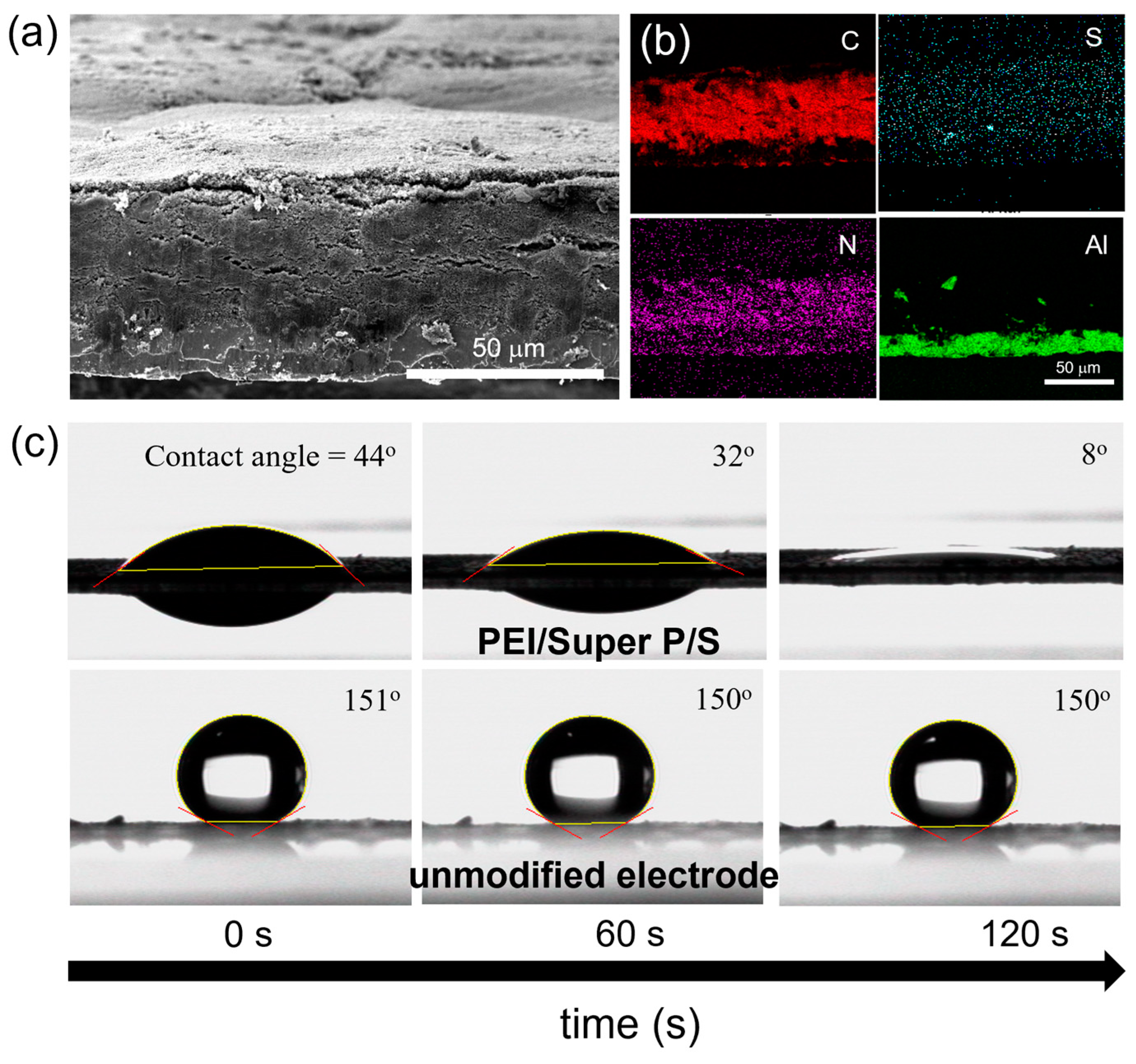
3.1. Characterization of the Electrode Structure and Surface Properties of PEI/SuperP/S Electrodes

The cathode in this study was fabricated using commercial Super P and sulfur particles, which exhibited a size distribution in the tens of micrometers. Figure 1a presents an SEM image of the cross-section of a PEI/Super P-modified electrode. This modification results in a 5 μm-thick coating layer that serves as an enhanced current collector on the electrode surface. To increase energy storage density, it is necessary to reduce the thickness of the PEI/Super P coating layer. Within the scope of our experiments, a thickness of 5 μm for the PEI/Super P layer was found to be the thinnest thickness that effectively suppressed the shuttle effect caused by polysulfides while maintaining charge–discharge stability. The direct formation of the PEI/Super P coating layer on the electrode not only ensures improved contact area and effective LiPS trapping but also serves as a secondary cathode. Figure 1b displays the elemental mapping of the PEI/Super P-coated sulfur electrode using EDS. Interestingly, the presence of nitrogen (N) in the EDS map confirms the uniform distribution of PEI across the electrode, comprising sulfur, Super P and PVDF. The uniform distribution of nitrogen throughout the cathode is presumably due to the diffusion of PEI into the sulfur/Super P layer during the PEI/Super P coating and electrode drying process. This well-dispersed PEI fills the pores generated during NMP evaporation, rendering the electrode surface hydrophilic. Figure 1c presents the wettability of the electrode, as indicated by measured contact angles of 44° and 151° for electrodes with and without the PEI/Super P coating, respectively. These contact angles reveal the compatibility of the electrode with polar electrolytes and LiPSs generated during cycling. A more wettable electrode enhances electrolyte penetration and facilitates Li+-ion transport, thereby improving cycling performance through better interaction with surface-adherent LiPSs [40].

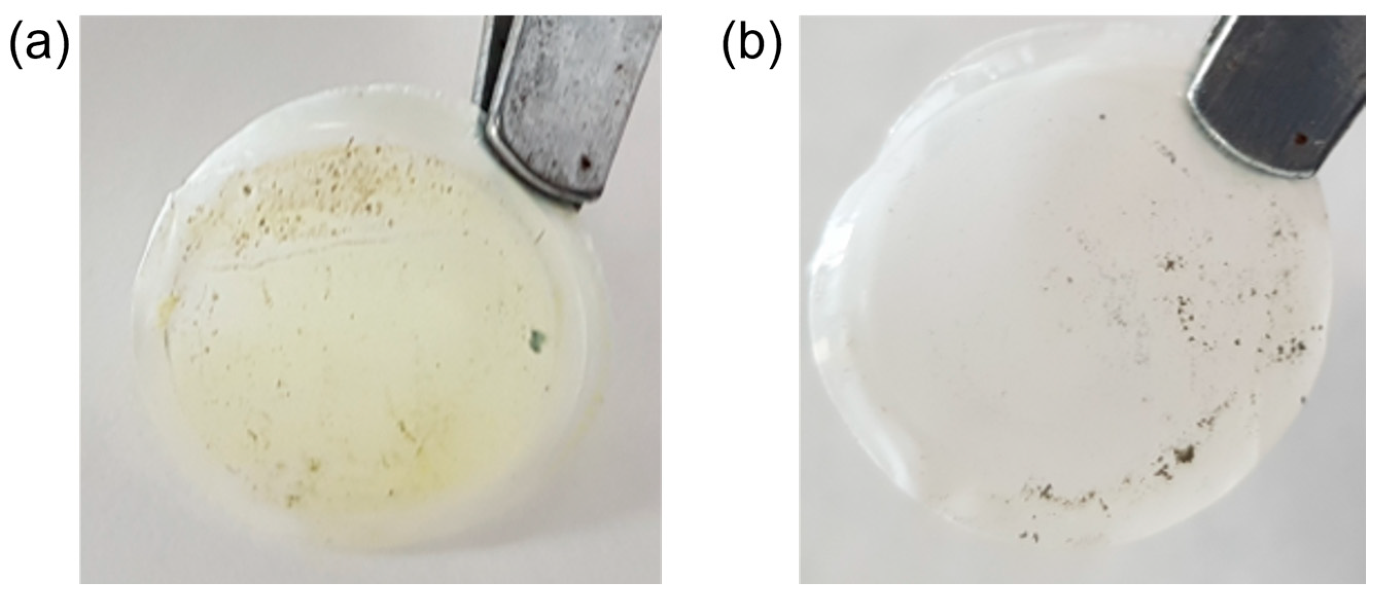
3.2. Symmetric Cell Experiment to Investigate the Impact of PEI/Super P

The CV of a symmetric cell with identical working and counter electrodes was employed to investigate the impact of introducing PEI/Super P to the cathode of a Li–S battery (Figure 2a–c). Li2S6 was used as an electroactive material in the symmetric cells. Neither does PVDF interact with polysulfides, nor does it affect the electrochemical reaction, so PVDF/Super P was used as a control group in comparison to PEI/Super P. A 0.5 M Li2S6 electrolyte served as the electroactive species. Redox currents reveal an electrochemical reaction between the electrode and LiPSs. To assess the capacity contribution of each electrode, cells without Li2S6 catholyte were also evaluated. In the absence of Li2S6, no current was developed. Given that Li2S6 is the sole electrochemically active species in the experiment, it is oxidized to elemental sulfur at one electrode and reduced at the counter electrode. CV profiles were recorded over a –1.2 V to 1.2 V range at various scan rates. Six distinct peaks in the CV of the PEI/Super P electrode signify redox reactions, while the PVDF/Super P electrode showed only a broad peak at −0.71 V and 0.71 V as shown in Figure 2a. In PEI/Super P electrodes, peaks at 0.46 V and 0.79 V are attributed to the oxidation of Li2S6 to sulfur and its subsequent reduction to Li2S2 or Li2S at the counter electrode [41]. The peaks at −0.46 and −0.79 V exhibit the same shape and current density as those observed during Li2S6 oxidation. The well-defined and separate peaks indicate efficient polysulfide redox reactions at the electrode [42]. The peaks observed at 0.11 and −0.11 V correspond to the oxidation and reduction between Li2S or Li2S2 and LiPSs, respectively. In contrast, the PVDF/Super P electrode exhibits merged peaks at −0.71 V and 0.71 V, without the distinct peak separation observed in the PEI/Super P-modified electrode. These fewer and broader peaks suggest sluggish reaction kinetics and higher energy requirements for polysulfide conversion. These findings demonstrate that PEI/Super P enhances electrochemical reactions of redox pairs derived from sulfur species. Recent studies have reported catalytic effects involving amine groups, necessitating further investigation into the electrochemical interactions between amines and LiPSs during cycling [43,44].
In the CV analysis shown in Figure 2b,c for PEI/Super P and PVDF/Super P electrodes, the current for PEI/Super P electrode noticeably increases as the scan speed increases, in contrast to the PVDF/Super P electrode. Moreover, compared to the PVDF/Super P electrode, peaks in the PEI/Super P electrode remain well-separated even at high scan rates. These observations indicate that the PEI/Super P electrode has the dual function of adsorbing polysulfides and boosting the electrochemical reaction kinetics. In the Nyquist plot from Figure 2d, obtained from EIS measurements on symmetric cells, the size of the semicircle in the high-frequency region corresponds to the charge transfer resistance (Rct). In this context, the PEI/Super P electrode exhibits a lower Rct compared to a conventional electrode [45].

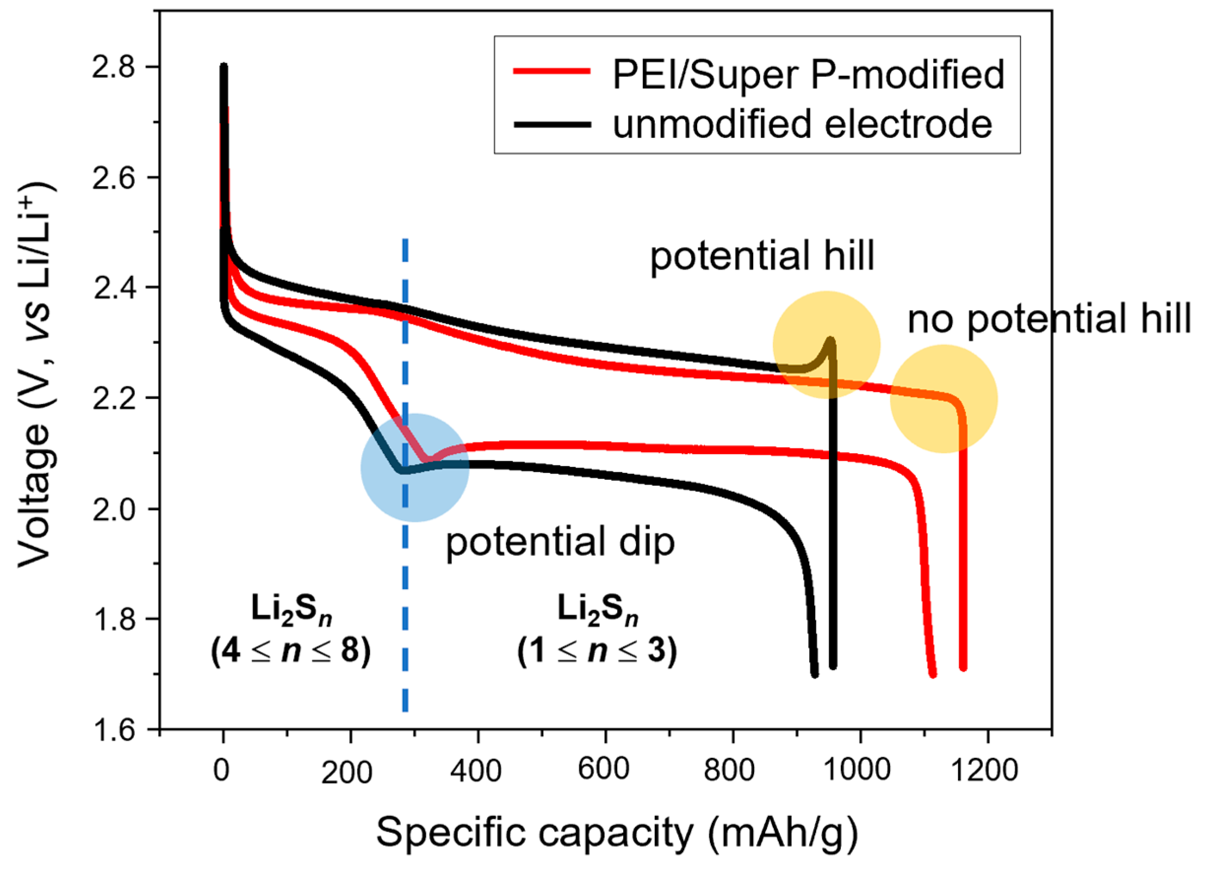
3.3. Assessment of the Electrochemical Behavior of PEI/Super P/S Electrodes

Figure 3 depicts the galvanostatic charge–discharge profile for the sulfur cathode with and without the PEI/Super P coating. The galvanostatic charge–discharge profiles were used to investigate the behavior of LiPSs in Li–S cells with and without PEI/Super P coating on sulfur cathode. During the discharge process, a potential dip is commonly observed in both the PEI/Super P/S and the unmodified cathode. This can be attributed to the increase in electrolyte viscosity as sulfur transitions to polysulfides, leading to a significant decrease in Li+ ion diffusion [46]. Additionally, the crystallization of Li2S2 also demands more energy, further contributing to this observation. This is due to a substantial energy barrier for initiating crystal nucleation as the system transitions from the homogeneous phase to the heterogeneous phase. During the charging process, a clear potential hill is observed in the galvanostatic profile of the unmodified cell due to the phase nucleation of Li2S2/Li2S [46]. The insulating nature of the formed Li2S2/Li2S within the cathode during discharge necessitates a substantial overpotential when these species are converted back to LiPSs. In contrast, for sulfur cathodes modified with PEI/Super P, this potential hill is entirely absent. The absence of such a potential hill implies that PEI/Super P significantly reduces the activation energy during the oxidation process of insulating Li2S, thereby increasing energy efficiency [46]. The presence of amine groups in PEI seems to facilitate the even distribution of small-sized Li2S2/Li2S particles within the cathode during the discharge process. Additionally, the catalytic effect of the amine groups is believed to play a role in this enhancement. For larger Li2S2/Li2S particles, which are electrically insulating and impede the mobility of Li+ ions, a substantial activation energy is needed for their conversion to LiPSs [47].
To evaluate the impact of PEI/Super P on Li–S battery performance, electrochemical assessments were conducted on electrodes with and without the application of PEI/Super P coating on the sulfur cathode, with varying charge–discharge rates. To minimize the experimental variability, we compared roll-pressed sulfur electrodes with identical ones that had been coated with PEI/Super P, testing both under the same conditions. The initial constant-current charge–discharge curves at current densities ranging from 0.2 C to 2 C are presented in Figure 4a,b. Comparative analysis revealed that the PEI/Super P/S electrode exhibited lower voltage differences (∆E) and higher discharge capacity than the unmodified. As the scan rate increases, the PEI/Super P/S electrode shows a significantly smaller increase in ∆E, exhibiting a high specific capacity even at faster charge–discharge rates while the unmodified sulfur electrode exhibits large increase in ∆E. The electrochemical behavior of the cell was further probed using CV profiles as shown in Figure 4c,d. Over six cycles, the CV profiles of both the PEI/Super P/S electrode and the unmodified sulfur electrode remained consistent. For the PEI/Super P/S electrode, two clear cathodic peaks emerge at approximately 2.3 V and 2.03 V, attributed to the conversion of elemental sulfur to long-chain polysulfides and then to short-chain polysulfides respectively. During the oxidation process, two overlapping peaks observed at 2.38 V and 2.45 V indicate the transformation from insoluble sulfide back to soluble polysulfides, and ultimately to elemental sulfur [48]. Compared to the PEI/Super P/S electrode, the unmodified sulfur electrode exhibits a larger voltage difference between the second cathodic peak appearing at 2.01 V and the anodic peak at 2.49 V. Additionally, the width of the current peak is considerably broad. Such observations clearly indicate that the PEI/Super P coating is enhancing the redox reaction kinetics between sulfur and Li2Sn.
EIS measurement results for the PEI/Super P/S and unmodified sulfur cell are presented in Figure 5a. In the Nyquist plot obtained before cycling, the initial intercept on the Z’ axis of the semicircle represents the electrolyte resistance (Rs). The subsequent intercept on the Z´ axis corresponds to the sum of the charge transfer resistance (Rct) at interfaces such as the cathode/electrolyte and anode/electrolyte. Meanwhile, the straight line suggests limitations in Li+ ion diffusion, represented by the Warburg resistance [49,50]. The measured Rs values of the evaluated cells were 6.3 Ω and 5.0 Ω respectively, which indicates that modification of the cathode has almost no influence on Li+ ion diffusion in the electrolyte. For the charge transfer resistance, the size of the semicircle indicates that the PEI/Super P/S electrode has a much smaller value compared to the unmodified electrode. This means that the PEI/Super P-modification induces a reduction in the overpotential required for charge transfer at the cathode surface, leading to enhanced energy-utilization efficiency. Figure 5b illustrates the impedance changes after 300 discharge cycles. The magnitude of the second semicircle after discharge is indicative of insulating and insoluble Li2S deposition on the active surface of the electrode [51]. This Li2S layer hampers charge transfer, resulting in increased battery polarization. Consequently, this leads to premature termination of the discharge process [52]. During the charging process in the EIS pattern as shown in Figure 5c, insulating Li2S layers on the electrode surface are oxidized to polysulfides and then revert to sulfur [53]. For both charging and discharging processes, the magnitudes of the second semicircles are significantly reduced with the PEI/Super P-modification compared to the unmodified sulfur cathode. As a result, PEI/Super P-modification not only suppresses the shuttle effect of LiPSs but also enhances electron transfer reaction kinetics at the interfaces.

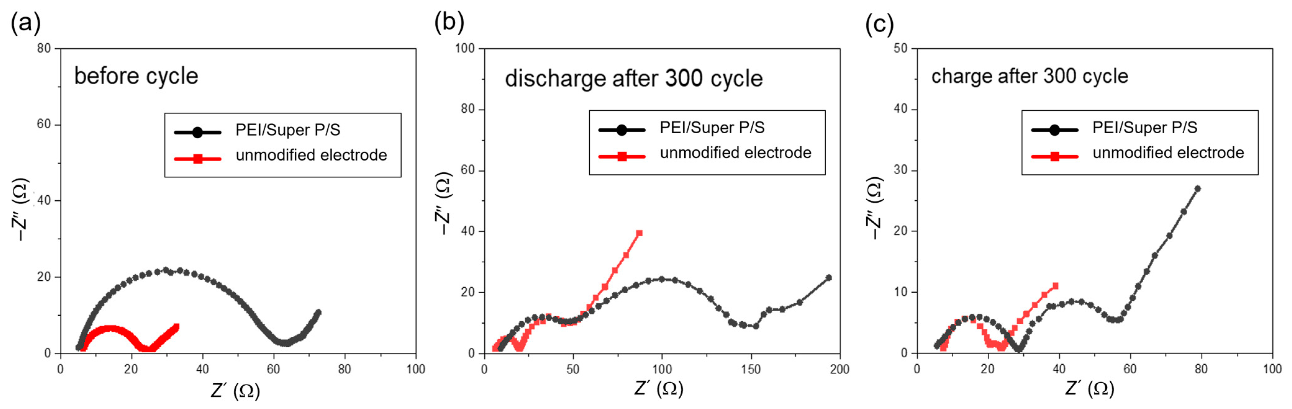
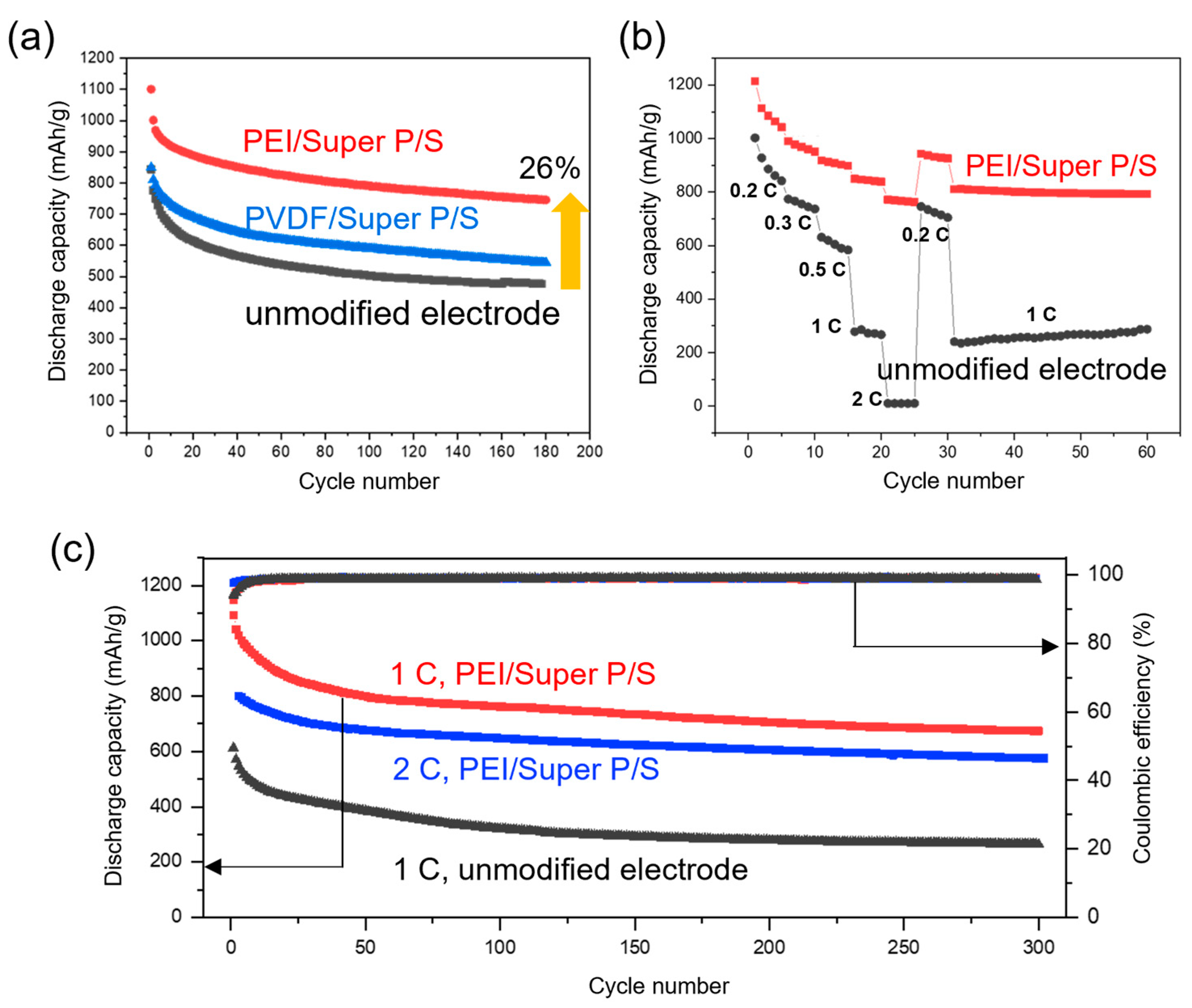
3.4. Cycling Performance and Rate Capability of PEI/Super P/S Electrode

Figure 6a displays the cycle performance based on polymer type, elucidating the influence of PEI/Super P-modification on sulfur electrode compared to the PVDF/Super P/S electrode. Electrodes were prepared using either PEI/Super-P on sulfur electrode or, as a control group, PVDF/Super P coatings on sulfur electrode, and tested at a current density of 0.5 C. By means of this experiment, we could determine how much the additional PEI/Super P coating contributes to the performance improvement of the Li–S battery. Cells with PEI/Super P and PVDF/Super P exhibited discharge capacities of 1102 mAh/g and 851 mAh/g, respectively, while unmodified standard Li–S cells delivered 819 mAh/g. The corresponding degrees of sulfur utilization were 65.8%, 50.8%, and 48.9%, which were calculated by dividing the experimental discharge capacities of the first cycles by the theoretical discharge capacity of Li–S batteries (1675 mAh/g). The Coulombic efficiency for PEI/Super P-modified, PVDF/Super P-modified and unmodified standard cells remained above 98% of their initial values, which were 96.2%, 96.7%, and 94.3%, respectively, over 200 cycles. PVDF/Super P/S cell exhibited an initial discharge capacity similar to standard cells and maintained relatively stable performance thereafter. In contrast, the PEI/Super P modified cell showed an initial discharge capacity approximately 26% higher than the other cells.
To assess rate capability, each cell underwent five charge–discharge cycles at various current densities, as depicted in Figure 6b. The discharge capacity for each cell decreases as the scan rate increases; however, the PEI/Super P-modified sulfur cell exhibited superior performance, particularly at high current densities. Upon reverting from 2 C to a lower current density of 0.2 C after five cycles, the PEI/Super P-modified sulfur cell restored a high discharge capacity of 942 mAh/g. Subsequent cycling at 1 C demonstrated a negligible decay rate of 0.011% per cycle in discharge capacity. The sulfur electrode, not modified with PEI/Super P, exhibited only negligible current density at a 2 C discharge condition. Figure 6c depicts the long-term fast charge–discharge behavior. The PEI/Super P/S electrode consistently delivered stable discharge capacities under high current densities of 1 C and 2 C. Notably, it exhibited an initial discharge capacity of 787 mAh/g at 2 C and sustained a capacity of 575 mAh/g (73% retention) even after 300 cycles. Conversely, a standard cell could only uphold a discharge capacity of 330 mAh/g after 300 cycles at 1 C. This superior performance highlights the efficacy of the PEI/Super P modification on the electrode. The data suggests that the shuttle effect observed during cycling can be effectively mitigated and there is a substantial improvement in redox kinetics due to the PEI/Super P coating.
To confirm the suppression of the shuttle effect by the PEI/Super P coating layer, the coin cell was subjected to 200 charge–discharge cycles at the 1 C rate. Subsequently, the coin cell was disassembled, and the surface of the separator was observed. As shown in Figure 7, the surface of the unmodified cell’s separator was heavily contaminated due to the diffusion of polysulfides. In contrast, the separator of the coin cell modified with PEI/Super P showed no traces of yellow sulfur contamination. From this, it can be confirmed that the PEI/Super P coating layer effectively suppresses the polysulfide shuttle effect.

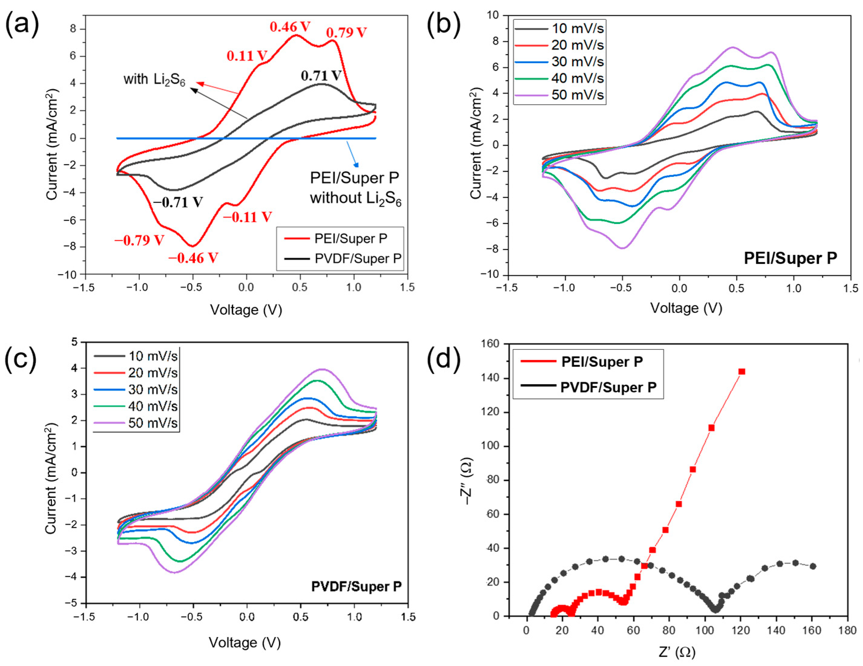
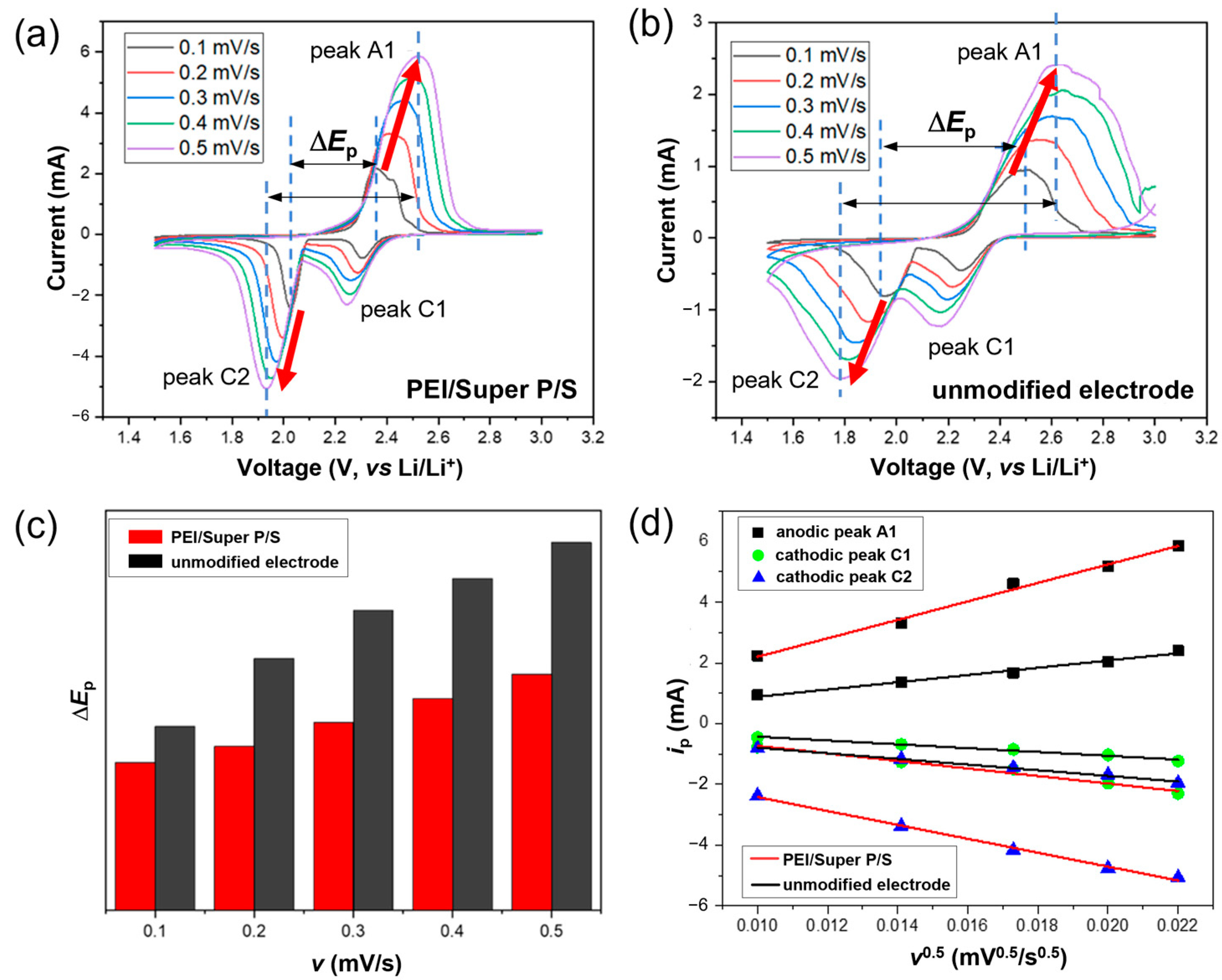
3.5. Cyclic Voltammetry Studies of the PEI/Super P/S Electrode

Figure 8a,b displays the CV scan results for PEI/Super P/S and unmodified standard sulfur cells. Figure 8c displays a graph comparing the voltage difference (∆Ep) of the cell values of PEI/Super P/S and standard sulfur cells as a function of scan rate, estimated from CV plots. During repeated charge–discharge cycles, ∆Ep increases with each cycle for both cells. However, the increase in ∆Ep values of PEI/Super P/S significantly decreases with the increase in scan rate compared to the standard sulfur electrode. This implies that the PEI/Super P-modification can greatly facilitate the conversion between Li2S and sulfur, which takes place through LiPSs, minimizing the energy loss during the charge–discharge process [54].
Introducing a new coating layer between the sulfur cathode and separator may hinder Li+ ion diffusion. Therefore, the diffusion coefficients of Li+ ion were determined on cells with PEI/Super P/S at different scan rates [34]. The Randles–Sevcik equation (Equation (1)) was used to estimate the Li+ ion diffusion coefficient [25]:
i p = 2.69 × 10 5 n 3 / 2 A D a p p 1 / 2 C v 1 / 2
where A (cm2) is electrode area, C (mol/cm3) is the Li+ ion concentration in the bulk solution, v is the scan rate (V/s), Dapp is the apparent diffusion coefficient (cm2/s), ip (A) is the peak current and n is the number of electrons transferred during the electrochemical reactions. It should be noted that the Li+ ion diffusion within Li–S batteries is a complicated process, encompassing phase transitions, interfacial migration, and redox reaction between sulfur and Li2S via LiPSs. Furthermore, the experimentally measured effective surface area of the working electrode greatly exceeds its geometric counterpart. Consequently, the Li+ ion diffusion coefficient, as determined by the Randles–Sevcik equation in this study, represents the apparent diffusion coefficient [55,56,57]. The apparent diffusion coefficients of Li+ ion were calculated at various scan rates for the three peak currents: peak A1, peak C1, and peak C2. A linear relationship exists between the square root of the scan rate and the peak current, as depicted in Figure 8d. In each cell, the lowest apparent diffusion coefficient corresponds to the reduction peak (peak C1 as shown in Figure 8a,b), which represents the step where elemental sulfur is reduced to LiPSs. Peaks C2 and A1 correspond to the electrochemical reactions between the Li2S4/Li2S2 redox pair [53]. The PEI/Super P-modified cell exhibited apparent diffusion coefficients of 1.05 × 10⁻⁷ cm2/s at the oxidation peak and values of 4.16 × 10⁻⁸ and 9.18 × 10⁻⁸ at the two reduction peaks. This distinctly contrasts with coefficients of 4.35 × 10⁻⁸ cm2/s for oxidation and 2.23 × 10⁻⁸, 3.53 × 10⁻⁸ cm2/s for reduction seen in a standard sulfur cell. Across all peaks, the PEI/Super P/S apparent diffusion coefficient outperforms that of standard cells. Such outcomes highlight the improved Li+ ion mobility within the battery, even with new impediments on the electrode surface. When a PEI/Super P layer is coated as described, the reason for the increased Li+ ion diffusion rate is speculated to be due to the PEI/Super P coating layer serving as a supplementary electrode function. The amine groups in the PEI layer effectively capture LiPSs, promoting rapid redox reactions. Additionally, the hydrophilic nature of the PEI layer ensures efficient contact with the electrolyte, which likely contributes to the enhanced Li+ ion diffusion rate [34,40].

4. Conclusions

PEI/Super P coating was applied to the sulfur cathode to mitigate the shuttle effect, leading to improved cycling stability and rate performance of Li–S batteries. The PEI/Super P helps suppress the diffusion of LiPSs by both trapping them and facilitating the redox process. Despite the additional PEI/Super P coating layer between the sulfur cathode and the separator, the diffusion rate of Li+ ions significantly increased, while noticeably reducing the charge transfer resistance. The hydrophilic properties of the PEI/Super P coating facilitate electrolyte penetration into the cathode, ensuring fast diffusion of Li+ ions. Furthermore, our design exhibited superior energy efficiency by notably diminishing polarization in comparison to unmodified Li–S cells across various current densities. This ensures remarkable capacity retention during rapid charge–discharge cycles. From the perspective of commercializing Li–S batteries, the PEI/Super P-modified electrode fabrication technique is cost-effective, avoiding more expensive methods.

Supplementary Materials

The following supporting information can be downloaded at: https://www.mdpi.com/article/10.3390/batteries9110531/s1, Figure S1: BET adsorption-desorption isotherm and BJH pore size distribution; Table S1: BET surface area, BJH average pore size, and pore volume; Figure S2: Raman spectra.

Author Contributions

Conceptualization, J.H. and J.J.; methodology, J.H., P.J.K. and J.J.; validation, G.M., J.B.L., H.K. and W.-G.L.; investigation, J.H., G.M., J.B.L., P.J.K. and H.K; resources, P.J.K., K.S., I.W.C., S.Y., J.L. and J.J.; writing—original draft preparation, J.H. and J.J.; writing—review and editing, J.H., K.S., I.W.C. and J.J.; visualization, J.H.; supervision, S.Y., J.L. and J.J.; project administration, J.J.; funding acquisition, J.J. All authors have read and agreed to the published version of the manuscript.

Funding

This research was supported by the Nano & Material Technology Development Program through the National Research Foundation of Korea (NRF) funded by Ministry of Science and ICT (NRF-2022M3H4A3095299).

Data Availability Statement

The data is available upon request.

Conflicts of Interest

The authors declare no conflict of interest.

References

  1. Nitta, N.; Wu, F.; Lee, J.T.; Yushin, G. Li-ion battery materials: Present and future. Mater. Today 2015, 18, 252–264. [Google Scholar] [CrossRef]
  2. Ma, L.; Hendrickson, K.E.; Wei, S.; Archer, L.A. Nanomaterials: Science and applications in the lithium-sulfur battery. Nano Today 2015, 10, 315–338. [Google Scholar] [CrossRef]
  3. Manthiram, A.; Chung, S.H.; Zu, C. Lithium-sulfur batteries: Progress and prospects. Adv. Mater. 2015, 27, 1980–2006. [Google Scholar] [CrossRef] [PubMed]
  4. Urbonaite, S.; Poux, T.; Novák, P. Progress towards commercially viable Li-S battery cells. Adv. Energy Mater. 2015, 5, 1500118. [Google Scholar] [CrossRef]
  5. Huang, L.; Li, J.; Liu, B.; Li, Y.; Shen, S.; Deng, S.; Lu, C.; Zhang, W.; Xia, Y.; Pan, G.; et al. Electrode design for lithium-sulfur batteries: Problems and solutions. Adv. Funct. Mater. 2020, 30, 1910375. [Google Scholar] [CrossRef]
  6. Rosenman, A.; Markevich, E.; Salitra, G.; Aurbach, D.; Garsuch, A.; Chesneau, F.F. Review on Li-sulfur battery systems: An integral perspective. Adv. Energy Mater. 2015, 5, 1500212. [Google Scholar] [CrossRef]
  7. Guo, J.; Xu, Y.; Wang, C. Sulfur-impregnated disordered carbon nanotubes cathode for lithium-sulfur batteries. Nano Lett. 2011, 11, 4288–4294. [Google Scholar] [CrossRef]
  8. Zheng, M.; Chi, Y.; Hu, Q.; Tang, H.; Jiang, X.; Zhang, L.; Zhang, S.; Pang, H.; Xu, Q. Carbon nanotube-based materials for lithium-sulfur batteries. J. Mater. Chem. A 2019, 7, 17204–17241. [Google Scholar] [CrossRef]
  9. Zheng, G.; Yang, Y.; Cha, J.J.; Hong, S.S.; Cui, Y. Hollow carbon nanofiber-encapsulated sulfur cathodes for high specific capacity rechargeable lithium batteries. Nano Lett. 2011, 11, 4462–4467. [Google Scholar] [CrossRef]
  10. Wang, H.; Yang, Y.; Liang, Y.; Robinson, J.T.; Li, Y.; Jackson, A.; Cui, Y.; Dai, H. Graphene-wrapped sulfur particles as a rechargeable lithium-sulfur battery cathode material with high capacity and cycling stability. Nano Lett. 2011, 11, 2644–2647. [Google Scholar] [CrossRef]
  11. Ji, L.; Rao, M.; Zheng, H.; Zhang, L.; Li, Y.; Duan, W.; Guo, J.; Cairns, E.J.; Zhang, Y. Graphene oxide as a sulfur immobilizer in high performance lithium/sulfur cells. J. Am. Chem. Soc. 2011, 133, 18522–18525. [Google Scholar] [CrossRef]
  12. He, G.; Ji, X.; Nazar, L. High “C” rate Li-S cathodes: Sulfur imbibed bimodal porous carbons. Energy Environ. Sci. 2011, 4, 2878–2883. [Google Scholar] [CrossRef]
  13. Ji, X.; Lee, K.T.; Nazar, L.F. A highly ordered nanostructured carbon-sulphur cathode for lithium-sulphur batteries. Nat. Mater. 2009, 8, 500–506. [Google Scholar] [CrossRef] [PubMed]
  14. Evers, S.; Nazar, L.F. New approaches for high energy density lithium-sulfur battery cathodes. Acc. Chem. Res. 2013, 46, 1135–1143. [Google Scholar] [CrossRef] [PubMed]
  15. Lim, W.-G.; Mun, Y.; Cho, A.; Jo, C.; Lee, S.; Han, J.W.; Lee, J. Synergistic effect of molecular-type electrocatalysts with ultrahigh pore volume carbon microspheres for lithium-sulfur batteries. ACS Nano 2018, 12, 6013–6022. [Google Scholar] [CrossRef] [PubMed]
  16. Fan, C.-Y.; Yuan, H.-Y.; Li, H.-H.; Wang, H.-F.; Li, W.-L.; Sun, H.-Z.; Wu, X.-L.; Zhang, J.-P. The effective design of a polysulfide-trapped separator at the molecular level for high energy density Li-S batteries. ACS Appl. Mater. Interfaces 2016, 8, 16108–16115. [Google Scholar] [CrossRef]
  17. Pang, Q.; Kundu, D.; Cuisinier, M.; Nazar, L.F. Surface-enhanced redox chemistry of polysulphides on a metallic and polar host for lithium-sulphur batteries. Nat. Commun. 2014, 5, 4759. [Google Scholar] [CrossRef]
  18. Liang, X.; Hart, C.; Pang, Q.; Garsuch, A.; Weiss, T.; Nazar, L.F. A highly efficient polysulfide mediator for lithium-sulfur batteries. Nat. Commun. 2015, 6, 5682. [Google Scholar] [CrossRef]
  19. Pu, J.; Shen, Z.; Zheng, J.; Wu, W.; Zhu, C.; Zhou, Q.; Zhang, H.; Pan, F. Multifunctional Co3S4@sulfur nanotubes for enhanced lithium-sulfur battery performance. Nano Energy 2017, 37, 7–14. [Google Scholar] [CrossRef]
  20. Zhang, Q.; Zhang, X.; Li, M.; Liu, J.; Wu, Y. Sulfur-deficient MoS2−x promoted lithium polysulfides conversion in lithium-sulfur battery: A first-principles study. Appl. Surf. Sci. 2019, 487, 452–463. [Google Scholar] [CrossRef]
  21. Yang, Z.-Z.; Wang, H.-Y.; Lu, L.; Wang, C.; Zhong, X.-B.; Wang, J.-G.; Jiang, Q.-C. Hierarchical TiO2 spheres as highly efficient polysulfide host for lithium-sulfur batteries. Sci. Rep. 2016, 6, 22990. [Google Scholar] [CrossRef] [PubMed]
  22. Su, Y.-S.; Manthiram, A. Lithium-sulphur batteries with a microporous carbon paper as a bifunctional interlayer. Nat. Commun. 2012, 3, 1166. [Google Scholar] [CrossRef] [PubMed]
  23. Su, Y.-S.; Manthiram, A. A new approach to improve cycle performance of rechargeable lithium-sulfur batteries by inserting a free-standing MWCNT interlayer. Chem. Commun. 2012, 48, 8817–8819. [Google Scholar] [CrossRef] [PubMed]
  24. Singhal, R.; Chung, S.-H.; Manthiram, A.; Kalra, V. A free-standing carbon nanofiber interlayer for high-performance lithium-sulfur batteries. J. Mater. Chem. A 2015, 3, 4530–4538. [Google Scholar] [CrossRef]
  25. Huang, J.-Q.; Zhuang, T.-Z.; Zhang, Q.; Peng, H.-J.; Chen, C.-M.; Wei, F. Permselective graphene oxide membrane for highly stable and anti-self-discharge lithium-sulfur batteries. ACS Nano 2015, 9, 3002–3011. [Google Scholar] [CrossRef]
  26. Zhang, Z.; Lai, Y.; Zhang, Z.; Zhang, K.; Li, J. Al2O3-coated porous separator for enhanced electrochemical performance of lithium sulfur batteries. Electrochim. Acta 2014, 129, 55–61. [Google Scholar] [CrossRef]
  27. Liu, M.; Li, Q.; Qin, X.; Liang, G.; Han, W.; Zhou, D.; He, Y.-B.; Li, B.; Kang, F. Suppressing self-discharge and shuttle effect of lithium-sulfur batteries with V2O5-decorated carbon nanofiber interlayer. Small 2017, 13, 1602539. [Google Scholar] [CrossRef]
  28. Li, X.; Banis, M.; Lushington, A.; Yang, X.; Sun, Q.; Zhao, Y.; Liu, C.; Li, Q.; Wang, B.; Xiao, W.; et al. A high-energy sulfur cathode in carbonate electrolyte by eliminating polysulfides via solid-phase lithium-sulfur transformation. Nat. Commun. 2018, 9, 4509. [Google Scholar] [CrossRef]
  29. Lim, S.; Lilly Thankamony, R.; Yim, T.; Chu, H.; Kim, Y.-J.; Mun, J.; Kim, T.-H. Surface modification of sulfur electrodes by chemically anchored cross-linked polymer coating for lithium-sulfur batteries. ACS Appl. Mater. Interfaces 2015, 7, 1401–1405. [Google Scholar] [CrossRef]
  30. Zheng, G.; Zhang, Q.; Cha, J.J.; Yang, Y.; Li, W.; Seh, Z.W.; Cui, Y. Amphiphilic surface modification of hollow carbon nanofibers for improved cycle life of lithium sulfur batteries. Nano Lett. 2013, 13, 1265–1270. [Google Scholar] [CrossRef]
  31. Fu, Y.; Su, Y.-S.; Manthiram, A. Sulfur-carbon nanocomposite cathodes improved by an amphiphilic block copolymer for high-rate lithium-sulfur batteries. ACS Appl. Mater. Interfaces 2012, 4, 6046–6052. [Google Scholar] [CrossRef]
  32. Wang, G.; Lai, Y.; Zhang, Z.; Li, J.; Zhang, Z. Enhanced rate capability and cycle stability of lithium-sulfur batteries with a bifunctional MCNT@PEG-modified separator. J. Mater. Chem. A 2015, 3, 7139–7144. [Google Scholar] [CrossRef]
  33. Kim, J.H.; Seo, J.; Choi, J.; Shin, D.; Carter, M.; Jeon, Y.; Wang, C.; Hu, L.; Paik, U. Synergistic ultrathin functional polymer-coated carbon nanotube interlayer for high performance lithium-sulfur batteries. ACS Appl. Mater. Interfaces 2016, 8, 20092–20099. [Google Scholar] [CrossRef]
  34. Fan, L.; Li, M.; Li, X.; Xiao, W.; Chen, Z.; Lu, J. Interlayer material selection for lithium-sulfur batteries. Joule 2019, 3, 361–386. [Google Scholar] [CrossRef]
  35. Laverde, J.; Rosero-Navarro, N.C.; Miura, A.; Buitrago-Sierra, R.; Tadanaga, K.; López, D. Impact of sulfur infiltration time and its content in an N-doped mesoporous carbon for application in Li-S batteries. Batteries 2022, 8, 58. [Google Scholar] [CrossRef]
  36. He, Z.; Dou, X.; Liu, W.; Zhang, L.; Lv, L.; Liu, J.; Meng, F. Yeast-derived sulfur host for the application of sustainable Li–S battery cathode. Batteries 2023, 9, 289. [Google Scholar] [CrossRef]
  37. Zhang, L.; Ling, M.; Feng, J.; Liu, G.; Guo, J. Effective electrostatic confinement of polysulfides in lithium/sulfur batteries by a functional binder. Nano Energy 2017, 40, 559–565. [Google Scholar] [CrossRef]
  38. Ma, L.; Zhuang, H.L.; Wei, S.; Hendrickson, K.E.; Kim, M.S.; Cohn, G.; Hennig, R.G.; Archer, L.A. Enhanced Li-S batteries using amine-functionalized carbon nanotubes in the cathode. ACS Nano 2016, 10, 1050–1059. [Google Scholar] [CrossRef]
  39. Li, W.; Hicks-Garner, J.; Wang, J.; Liu, J.; Gross, A.F.; Sherman, E.; Graetz, J.; Vajo, J.J.; Liu, P. V2O5 polysulfide anion barrier for long-lived li-s batteries. Chem. Mater. 2014, 26, 3403–3410. [Google Scholar] [CrossRef]
  40. Bhargav, A.; He, J.; Gupta, A.; Manthiram, A. Lithium-sulfur batteries: Attaining the critical metrics. Joule 2020, 4, 285–291. [Google Scholar] [CrossRef]
  41. Yuan, Z.; Peng, H.-J.; Hou, T.-Z.; Huang, J.-Q.; Chen, C.-M.; Wang, D.-W.; Cheng, X.-B.; Wei, F.; Zhang, Q. Powering lithium-sulfur battery performance by propelling polysulfide redox at sulfiphilic hosts. Nano Lett. 2016, 16, 519–527. [Google Scholar] [CrossRef] [PubMed]
  42. Lin, H.; Yang, L.; Jiang, X.; Li, G.; Zhang, T.; Yao, Q.; Zheng, G.W.; Lee, J.Y. Electrocatalysis of polysulfide conversion by sulfur-deficient MoS2 nanoflakes for lithium-sulfur batteries. Energy Environ. Sci. 2017, 10, 1476–1486. [Google Scholar] [CrossRef]
  43. Du, Z.; Chen, X.; Hu, W.; Chuang, C.; Xie, S.; Hu, A.; Yan, W.; Kong, X.; Wu, X.; Ji, H.; et al. Cobalt in nitrogen-doped graphene as single-atom catalyst for high-sulfur content lithium-sulfur batteries. J. Am. Chem. Soc. 2019, 141, 3977–3985. [Google Scholar] [CrossRef] [PubMed]
  44. Wang, C.; Sun, L.; Li, K.; Wu, Z.; Zhang, F.; Wang, L. Unravel the catalytic effect of two-dimensional metal sulfides on polysulfide conversions for lithium-sulfur batteries. ACS Appl. Mater. Interfaces 2020, 12, 43560–43567. [Google Scholar] [CrossRef] [PubMed]
  45. Lin, H.; Zhang, S.; Zhang, T.; Ye, H.; Yao, Q.; Zheng, G.W.; Lee, J.Y. Elucidating the catalytic activity of oxygen deficiency in the polysulfide conversion reactions of lithium-sulfur batteries. Adv. Energy Mater. 2018, 8, 1801868. [Google Scholar] [CrossRef]
  46. Lim, W.G.; Kim, S.; Jo, C.; Lee, J. A comprehensive review of materials with catalytic effects in li-s batteries: Enhanced redox kinetics. Angew. Chem. Int. Ed. 2019, 58, 18746–18757. [Google Scholar] [CrossRef] [PubMed]
  47. Yang, Y.; Zheng, G.; Misra, S.; Nelson, J.; Toney, M.F.; Cui, Y. High-capacity micrometer-sized Li2S particles as cathode materials for advanced rechargeable lithium-ion batteries. J. Am. Chem. Soc. 2012, 134, 15387–15394. [Google Scholar] [CrossRef]
  48. Chung, S.-H.; Lai, K.-Y.; Manthiram, A. A facile, low-cost hot-pressing process for fabricating lithium-sulfur cells with stable dynamic and static electrochemistry. Adv. Mater. 2018, 30, 1805571. [Google Scholar] [CrossRef]
  49. Li, M.; Wahyudi, W.; Kumar, P.; Wu, F.; Yang, X.; Li, H.; Li, L.-J.; Ming, J. Scalable approach to construct free-standing and flexible carbon networks for lithium-sulfur battery. ACS Appl. Mater. Interfaces 2017, 9, 8047–8054. [Google Scholar] [CrossRef]
  50. Deng, Z.; Zhang, Z.; Lai, Y.; Liu, J.; Li, J.; Liu, Y. Electrochemical impedance spectroscopy study of a lithium/sulfur battery: Modeling and analysis of capacity fading. J. Electrochem. Soc. 2013, 160, A553–A558. [Google Scholar] [CrossRef]
  51. Cañas, N.A.; Hirose, K.; Pascucci, B.; Wagner, N.; Friedrich, K.A.; Hiesgen, R. Investigations of lithium-sulfur batteries using electrochemical impedance spectroscopy. Electrochim. Acta 2013, 97, 42–51. [Google Scholar] [CrossRef]
  52. Waluś, S.; Barchasz, C.; Bouchet, R.; Alloin, F. Electrochemical impedance spectroscopy study of lithium-sulfur batteries: Useful technique to reveal the Li/S electrochemical mechanism. Electrochim. Acta 2020, 359, 136944. [Google Scholar] [CrossRef]
  53. Qu, L.; Liu, P.; Yi, Y.; Wang, T.; Yang, P.; Tian, X.; Li, M.; Yang, B.; Dai, S. Enhanced cycling performance for lithium-sulfur batteries by a laminated 2D g-C3N4/graphene cathode interlayer. ChemSusChem 2019, 12, 213–223. [Google Scholar] [CrossRef] [PubMed]
  54. Senthil, C.; Kim, S.-S.; Jung, H.Y. Flame retardant high-power Li-S flexible batteries enabled by bio-macromolecular binder integrating conformal fractions. Nat. Commun. 2022, 13, 145. [Google Scholar] [CrossRef] [PubMed]
  55. Vassilieva, S.Y.; Levina, E.E.; Nikitina, V.A. Kinetic analysis of lithium intercalating systems: Cyclic voltammetry. Electrochim. Acta 2016, 190, 1087–1099. [Google Scholar] [CrossRef]
  56. Vujković, M.; Mentus, S. Potentiodynamic and galvanostatic testing of NaFe0.95V0.05PO4/C composite in aqueous NaNO3 solution, and the properties of aqueous Na1.2V3O8/NaNO3/NaFe0.95V0.05PO4/C battery. J. Power Sources 2016, 325, 185–193. [Google Scholar] [CrossRef]
  57. Zhou, L.; Danilov, D.L.; Qiao, F.; Wang, J.; Li, H.; Eichel, R.-A.; Notten, P.H.L. Sulfur reduction reaction in lithium–sulfur batteries: Mechanisms, catalysts, and characterization. Adv. Energy Mater. 2022, 12, 2202094. [Google Scholar] [CrossRef]
Scheme 1. An illustration depicting the process of the PEI/Super P coating on the sulfur cathode inhibiting the shuttle effect caused by LiPSs.
Batteries 09 00531 sch001
Figure 1. (a) Cross-sectional SEM image of the electrode modified with PEI/Super P. (b) EDS mapping of the sample used for the cross-sectional image in (a). (c) Contact angles over time for sulfur electrodes: modified with PEI/Super P (upper images) and unmodified (bottom images).
Batteries 09 00531 g001
Figure 2. (a) CV profiles of symmetric cells using PEI/Super P and PVDF/Super P electrodes. CV profiles of symmetric cells with (b) PEI/Super P and (c) PVDF/Super P electrodes at various scan rates. (d) EIS result of the symmetric cells for PEI/Super P and PVDF/Super P electrodes. The current densities were calculated using the electrode’s surface area.
Batteries 09 00531 g002
Figure 3. Galvanostatic charge–discharge profiles of the PEI/Super P/S and unmodified electrodes at a scan rate of 0.2 C.
Batteries 09 00531 g003
Figure 4. Voltage profiles of (a) the PEI/Super P-modified and (b) unmodified sulfur electrode under various current rates. (c) CV profiles of the PEI/Super P modified and (d) unmodified sulfur electrode at a scan rate of 0.1 mV/s.
Batteries 09 00531 g004
Figure 5. (a) Electrochemical impedance spectra before the cycle test. Nyquist plots during (b) discharge and (c) charge processes after 300 cycles at a scan rate of 0.5 C.
Batteries 09 00531 g005
Figure 6. (a) Cycle stability comparison for PEI/Super P/S, PVDF/Super P/S and unmodified sulfur electrode at the discharge rate of 0.5 C. (b) Rate capabilities of PEI/Super P/S and unmodified sulfur electrodes at various current densities. (c) Long-term cycle stability of the Li–S cells for PEI/Super P/S, PVDF/Super P/S, and unmodified sulfur electrode at the discharge rates of 1 C and 2 C.
Batteries 09 00531 g006
Figure 7. Separator surface images of (a) the unmodified cathode and (b) PEI/Super P-modified cathode taken after 200 charge–discharge cycles at the 1 C rate.
Batteries 09 00531 g007
Figure 8. CV scans of the electrode modified with (a) PEI/Super P/S and (b) the unmodified electrode, from scan rates of 0.1–0.5 mV/s. (c) Peak currents (ip) plotted against the square root of scan rates (v0.5). (d) Polarization (∆Ep) as a function of varying scan rates.
Batteries 09 00531 g008
Disclaimer/Publisher’s Note: The statements, opinions and data contained in all publications are solely those of the individual author(s) and contributor(s) and not of MDPI and/or the editor(s). MDPI and/or the editor(s) disclaim responsibility for any injury to people or property resulting from any ideas, methods, instructions or products referred to in the content.

