Article

Tuning Nitrogen-Doped Carbon Electrodes via Synthesis Temperature Adjustment to Improve Sodium- and Lithium-Ion Storage

by
Yuliya V. Fedoseeva
1,*,
Elena V. Shlyakhova
1,
Anna A. Vorfolomeeva
1,
Mariya A. Grebenkina
1,
Vitalii I. Sysoev
1,
Svetlana G. Stolyarova
1,
Evgeny A. Maksimovskiy
1,
Anna A. Makarova
2,
Alexander V. Okotrub
1 and
Lyubov G. Bulusheva
1,*
1
Nikolaev Institute of Inorganic Chemistry SB RAS, 3 Acad. Lavrentiev Ave., 630090 Novosibirsk, Russia
2
Physical Chemistry, Institute of Chemistry and Biochemistry, Free University of Berlin, 14195 Berlin, Germany
*
Authors to whom correspondence should be addressed.
Batteries 2023, 9(1), 45; https://doi.org/10.3390/batteries9010045
Submission received: 30 November 2022 / Revised: 29 December 2022 / Accepted: 3 January 2023 / Published: 6 January 2023
(This article belongs to the Special Issue High-Performance Sodium-Ion Batteries)

Abstract

:
Structural imperfections, heteroatom dopants, and the interconnected pore structure of carbon materials have a huge impact on their electrochemical performance in lithium-ion and sodium-ion batteries due to the specific ion transport and the dominant storage mechanism at surface defect sites. In this work, mesopore-enriched nitrogen-doped carbon (NC) materials were produced with template-assisted chemical vapor deposition using calcium tartrate as the template precursor and acetonitrile as the carbon and nitrogen source. The chemical states of nitrogen, the volume of mesopores, and the specific surface areas of the materials were regulated by adjusting the synthesis temperature. The electrochemical testing of NC materials synthesized at 650, 750, and 850 °C revealed the best performance of the NC-650 sample, which was able to deliver 182 mA·h·g−1 in sodium-ion batteries and 1158 mA·h·g−1 in lithium-ion batteries at a current density of 0.05 A·g−1. Our study shows the role of defect sites, including carbon monovacancies and nitrogen-terminated vacancies, in the binding and accumulation of sodium. The results provide a strategy for managing the carbon structure and nitrogen states to achieve a high alkali-metal-ion storage capacity and long cycling stability, thereby facilitating the electrochemical application of NC materials.

1. Introduction

Lithium-ion batteries (LIBs) are ubiquitous as a power storage source for numerous electronic devices and electric vehicles and are unlikely to be replaced by low-cost energy storage devices such as sodium-ion batteries (SIBs) in the near future due to manufacturing weaknesses. Despite the similar properties of lithium and sodium, the graphite anode material, which efficiently accumulates lithium ions, is unsuitable for use in SIBs. Calculations predict that the interlayer distance between planar graphitic layers for the successful insertion of Na+ ions should be more than 0.37 nm [1]. Recently, it was found that the adsorption mechanism of alkali-metal-ion storage is realized during the adsorption of Li+ and Na+ ions on the surfaces of carbon electrodes [2,3,4,5]. This is easy to detect experimentally through charge–discharge curves. Namely, the intercalation of Li+ or Na+ ions into the spaces between the graphitic layers produces a plateau at a potential of about 0.1 V vs. Li/Li+ or Na/Na+, while the slope region in the potential range between 0.5 and 1.5 V vs. Li/Li+ or Na/Na+ arises from chemical adsorption on the carbon surface. The adsorption process occurs at various cell potentials and does not give a clearly defined plateau. This indicates that various surface sites, such as the surfaces of pores, defects, functional groups, and impurity atoms, are attractive for binding alkali-metal ions.
Highly porous carbon materials consisting of randomly oriented curved few-layered graphitic walls have a large interlayer distance and a high specific surface area, as well as numerous pores and defect sites. According to recent experimental studies, hard carbon materials possess a remarkable SIB capacity of about 200 mA·h·g−1 at potentials below 1 V vs. Na/Na+ [6]. Recently, some researchers have achieved a very high reversible sodium-ion storage capacity exceeding 400 mA·h·g−1 at a low current density of 30 mA·g−1 for carbon materials produced via the pyrolysis of biomaterial precursors [7,8,9,10,11]. In the case of biomass-derived carbon, various heteroatoms, such as nitrogen and phosphorous, are incorporated into the graphitic structure and play an important role in the interactions with alkali metals.
Much attention has been paid to the nitrogen dopant. Nitrogen is usually found in graphitic-like materials such as pyridinic N, pyrrolic N, or graphitic N. According to the literature, edge-nitrogen doping improves the capacity and fast-charging performances of N-doped carbon materials in LIBs and SIBs [12,13,14,15]. Nitrogen doping disrupts the integrity of graphitic structures, generating new structural defects and nanopores, which allow metal ions to more effectively penetrate into the volume of the carbon electrode materials. Moreover, nitrogen-edge groups are active binding sites for Li+ and Na+ ions. Experimental observations and density functional theory (DFT) calculations show that the presence of nitrogen-containing groups significantly enhances the ability of carbon materials to accumulate Na+ ions [11,16,17,18]. The authors attribute the excellent electrochemical performance of N-doped carbon materials to the synergetic effects of disordered crystallite structures, interconnected porous structures, volume expansion buffering during cycling, and electron doping from nitrogen heteroatoms. DFT calculations confirm that the nitrogen doping of carbon materials enhances the interaction of Na+ ions with carbon, which leads to a significantly improved storage capacity [11]. Lee et al. theoretically revealed the increased binding energy of sodium on graphene with nitrogen-doped defects compared with that calculated for pure graphene [19]. The development of new highly porous carbon materials with larger numbers of adsorbing defects and nanoporous structures can improve the electrochemical performance of SIBs in terms of capacity and rate capability. It is shown that the use of template nanoparticles creates an interconnected porous structure in nitrogen-doped carbon materials, and the presence of nanopores minimizes the alkali-metal-ion diffusion length and facilitates the penetration of electrolytes into the surfaces of carbon electrodes [20,21]. Moreover, highly porous nitrogen-doped carbon three-dimensional nanostructures can be used as cathode hosts or cathode current collectors for long-life LIBs and other batteries to provide pathways for rapid electron transfer and ion transport [22,23,24,25].
In this work, we synthesized porous nitrogen-doped carbon (NC) materials with a simple chemical vapor deposition method using calcium tartrate as the template precursor and acetonitrile as the carbon and nitrogen sources [26,27]. The size of the pores formed from template nanoparticles, as well as the number of defects in the pseudo-graphitic structures and the chemical state of the incorporated nitrogen, were changed by tuning the synthesis temperature. Herein, using various characterization tools, the morphologies, structures, and compositions of NC materials synthesized at different temperatures were studied. Electrochemical tests of the NC materials in LIB and SIB cells were performed to explore the underlying mechanisms and to reveal the influence of structural aspects on the accumulation of alkali metals. An in situ near-edge X-ray adsorption fine structure spectroscopy (NEXAFS) study of sodium deposition on the NC surfaces and the results of DFT calculations of sodiated graphitic models revealed the role of graphene sheet curvature and vacancy defects, including nitrogen-terminated ones, in sodium adsorption.

2. Materials and Methods

2.1. Synthesis

All reagents used were of analytical grade and were purchased from Reachem (Moscow, Russia). Figure 1 shows a scheme of the synthesis of porous NC materials. To prepare calcium tartrate as the template precursor, a 1 M sodium bicarbonate aqueous solution was mixed with DL-tartaric acid (C4H6O6), and then, a 1 M calcium chloride aqueous solution was added dropwise to the reaction solution. The resulting white precipitate was filtrated and dried at room temperature followed by washing with several portions of deionized water.
The template-assisted synthesis of NC materials included three stages. First, calcium tartrate was decomposed in an argon atmosphere at a pressure of about 75 Torr for 10 min in a quartz tubular reactor pre-heated to 650, 750, or 850 °C. The decomposition products are nanoparticles of CaO and oxygenated carbon (CO0.15@CaO) [28]. Second, acetonitrile vapor was introduced to the reactor at the same temperature and under a dynamic vacuum (~75 Torr) for 30 min to coat nanoparticles with NC layers. Finally, the resulting NC@CaO sample was immersed in dilute hydrochloric acid to remove CaO and then washed with distilled water and dried in air at 100 °C overnight. Samples synthesized at temperatures of 650, 750, and 850 °C were denoted as NC-650, NC-750, and NC-850, respectively.

2.2. Characterization Instruments

The morphologies of samples were examined using scanning electron microscopy (SEM), on a JEOL JSM 6700F using an accelerating voltage of 15 kV, and transmission electron microscopy (TEM) on a JEOL-2010 microscope using an accelerating voltage of 200 kV. Raman spectra were measured with the spectrometer LabRAM HR Evolution (Horiba) using a 514 nm wavelength beam from a He-Ne laser. Nitrogen adsorption measurements were carried out with a «Sorbi-MS» analyzer at a temperature of 77 K. Before the measurements, the samples were degassed at 150 °C under a dynamic vacuum for 90 min. The total surface areas were calculated by means of the Brunauer–Emmett–Teller (BET) method. The total isotherms were obtained by measuring the adsorption curves at P/P0 from 0.06 to 0.99 and the desorption curves at P/P0 from 0.99 to 0.40. The specific surface areas, pore size distributions, and total pore volumes of the samples were determined from the total isotherms using the Brunauer–Emmett–Teller (BET) theory and statistical thickness surface area (STSA).
X-ray photoelectron spectroscopy (XPS) and NEXAFS measurements were carried out using the RGL-PES experimental station at the Russian–German beamline (RGBL) at the Berliner Elektronenspeicherring-Gesellschaft für Synchrotronstrahlung (BESSY II) operated by Helmholtz-Zentrum Berlin für Materialien und Energie. The NC samples were spread in a thin layer on the scratched surface of a Cu substrate. The samples were fixed on a holder, which was placed in an analytical vacuum chamber at a pressure of ~10−10 mbar. The XPS spectra were recorded with a PHOIBOS 150 electron-energy analyzer (SPECS GmbH, Berlin, Germany) operated at 50 eV pass energy and 0.1 eV step size for survey spectra, and 30 eV pass energy and 0.05 eV step size for N 1s and 0.025 eV step size for C 1s spectra, respectively. We used a photon energy of 830 eV for the acquisition of all the spectra. The binding energy of the Au 4f7/2 component at 84.0 eV measured from a clean gold foil was used to calibrate the XPS energy scale. N 1s spectra were fitted using a Gaussian/Lorentzian product function and a Shirley-type background within the Casa XPS software, Version 2.3.15 (Casa Software Ltd., Teignmouth, UK). The NEXAFS spectra were acquired in the leakage current measurement mode.
After the XPS and NEXAFS measurements, the samples were transferred into an ultra-high vacuum preparation chamber to deposit sodium vapors. Na was evaporated from a well-outgassed sodium dispenser (SAES Getters) at a current of ~7.8 A. The Na-containing dispenser was located at a distance of 15 cm from the holder with three samples. The deposition time was 40 min. After Na deposition, the holder was transferred to the analytical chamber without interaction with air. The XPS and NEXAFS spectra of the sodiated samples were measured with the same parameters as for the initial samples.

2.3. Electrochemical Measurements

The electrochemical performances of the samples were evaluated using a NEWARE CT-3008 (Neware Technology LTD., Shenzhen, China) charge–discharge station. The working electrode was made of NC material, which was grinded and mixed with polyvinylidene difluoride (10 wt.%), conductive additive super P (10 wt.%), and N-methylpyrrolidone solvent. The resulting paste was smeared on a copper foil disk and then dried at 80 °C for 12 h. A metal sheet of lithium or sodium was used as the counter electrode. Polypropylene for the LIBs or glass fiber for the SIBs were used as separators. For the LIBs, the electrolyte was 1 M LiPF6 in a mixture of ethylene carbonate and dimethyl carbonate (1:1 by volume). For the SIBs, the electrolyte was 1 M NaClO4 in a mixture of ethylene carbonate and dimethyl carbonate (1:1 by volume). To make the Li and Na half-cells, CR2032 coin cells were assembled in an argon glove box with less than 1 ppm of water and oxygen. The assembled half-cells were galvanostatically charged and discharged between 0.01 and 2.5 V vs. Li/Li+ or Na/Na+ at current densities of 50, 100, 250, 500, and 1000 mA·g−1 for 10 cycles per each current density.
Cyclic voltammetry (CV) and electrochemical impedance spectra (EIS) were recorded on a BCS-805 instrument (Biologic, Seyssinet-Pariset, France). CV curves were measured in the voltage range of 2.5–0.001 V vs. Li/Li+ or Na/Na+ at a potential scan rate of 0.1 mV·s−1 after 60 operation cycles in the galvanostatic mode. To study the kinetics of lithium or sodium storage, CV tests were performed at scan rates from 0.1 to 1.0 mV·s−1 for freshly assembled cells after 10 repeated discharge–charge cycles at 0.05 A·g−1.
The EIS spectra were recorded after three CV cycles at a scan rate of 0.1 mV·s−1 and one discharge–charge cycle at a current density of 0.5 A·g−1. The EIS spectra were obtained by applying an alternating voltage with an amplitude of 5 mV in the frequency range 10 mHz–10 kHz. Impedance spectra were recorded at an open cell potential of 2.5 V and then at an open cell potential of 0.001 V after the re-discharge.

2.4. Quantum Chemical Calculations

The calculations were performed using the M06 hybrid functional, parameterized for metal–organic systems [29], taking into account dispersion interactions using the D3 correction developed by Grimme et al. [30] as implemented in the Jaguar software package (Jaguar, version 10.3, Schrödinger, Inc., New York, NY, USA, 2019). The 6-31G basis set was used to describe atomic orbitals. Graphene fragments with vacancies, nitrogen inclusions, and pentagonal rings were used to model the surfaces of the NC materials. Hydrogen atoms terminated the fragment edges. The geometry of free models and models with Na atoms was fully optimized with the analytical gradient method to the default convergence criteria. The absence of imaginary frequencies indicated that the obtained geometries corresponded to the minima on the potential energy surfaces. The binding energy of Na with the model was calculated as Eb = ENa + Emodel − ENa+model, where the members are the total energies of the free Na atom, the free NC model, and the model with adsorbed Na. A positive value of Eb corresponds to the energy gain as a result of the interaction. In the case of adding two and three Na atoms, the Eb value was calculated relative to the model with a lower Na load.

3. Results

3.1. Structural Aspects

In the syntheses of the NC materials, simply prepared calcium tartrate was used as the template source. CaO nanoparticles derived from organic calcium precursors have a larger specific surface area and well-developed porosity than CaO obtained from inorganic components, as was previously demonstrated in [31,32]. According to a thermogravimetric analysis, the thermal decomposition of calcium tartrate in an inert atmosphere occurs in four stages, with the final salt decomposition at 650 °C, as shown in [33]. The composition and size of template nanoparticles can be controlled by the temperature of the synthesis process [34]. The SEM and TEM images show the morphologies of the NC materials synthesized at temperatures of 650, 750, and 850 °C (Figure 2).
Curved carbon walls organize spongy materials with a system of open and closed pores. At first glance, all the samples have a very similar morphology and are clusters of irregularly shaped agglomerates with a loose surface. Upon closer examination, it is seen that the surface friability was formed due to holes, which were more probably caused by the removal of template particles. Some of the pores in the NC materials repeat the shape of the template nanoparticles. Thus, an increase in the synthesis temperature leads to the growth of template nanoparticles due to their agglomeration. Consequently, macropores in NC materials also visually grow in size. According to the TEM images, the maximum pore size is ca. 10 nm in NC-650, ca. 20 nm in NC-750 and ca. 30 nm in NC-850. At 650 °C, the pyrolysis product of calcium tartrate contains a mixture of CaO and CaCO3 nanoparticles. As shown in [34], the subsequent decomposition of CaCO3 leads to the formation of gaseous carbon oxides, which etch the grown carbon layers in the process of their release. This etching process can lead to the formation of defects and the opening of pores. The TEM images of the NC materials demonstrate disordered structures of curved carbon walls; stacks of carbon layers visually become more graphitized with an increase in temperature. Small carbon vacancy defects are likely to heal at higher temperatures. Our early study of similar N-doped carbon materials via X-ray diffraction showed that an increase in the synthesis temperature leads to the ordering of graphitic layers and the formation of thicker stacks of layers [34]. Namely, the interlayer distance decreased from 3.79 to 3.58 Å, and the number of layers increased from 2 to 4 with an increase in the temperature from 650 to 850 °C. The pore structures of the NC samples were examined using N2 adsorption–desorption isotherms (Figure 3, Table 1). The isotherms show unlimited monolayer–multilayer adsorption up to P/P0 = 1 and belong to type II (Figure 3a). The isotherms of all the samples exhibit a sharp adsorption of N2 at low relative pressures (P/P0 < 0.01), which indicates the presence of a large number of micropores and ultramicropores. An H3-type hysteresis loop appears in the P/P0 range of 0.4–1.0 and is characteristic of mesoporous materials with a layered aggregation structure and wedge-shaped or slit-like pores [35]. The BET and STSA methods were used to calculate the specific surface areas, pore volumes, and pore size distributions for the NC materials. The specific surface areas decrease from 770 to 358 m2·g−1, and the pore volumes vary from 1.3 to 0.9 cm3·g−1 with an increase in the synthesis temperature from 650 to 850 °C (Table 1). The pore size distributions reveal a large amount of mesopores smaller than 30 nm in the samples (Figure 3b). NC-650 is enriched with small mesopores about 3 nm in diameter, and their volume decreases twice in NC-750 and NC-850. The average size of large mesopores increases from 8 to 15 nm with an increase in the synthesis temperature from 650 to 850 °C.
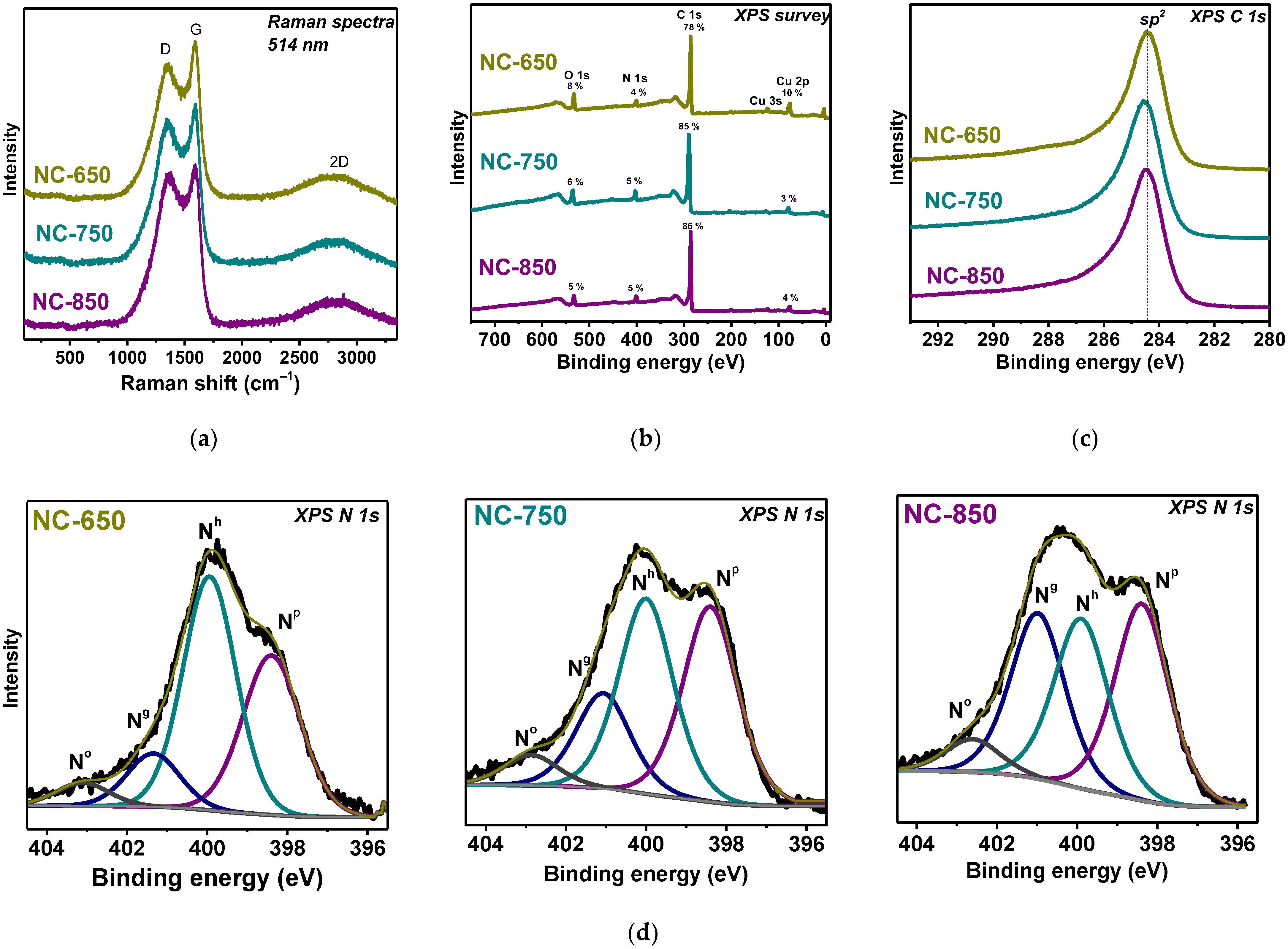
Raman scattering was used to provide chemical-specific information about the structures of the NC samples based on the fundamental vibrational modes (Figure 4a). The spectra of all the samples are dominated by two first-order Raman bands at 1580 cm−1 (G) and 1350 cm−1 (D). The G-bands occur as a result of the in-plane vibrational E2g mode involving sp2 hybridized carbon atoms in graphite structures, while the D-bands reflect the A1g breathing mode in aromatic rings and are caused by the presence of defects and structural disorders in graphitic planes. The first-order Raman bands are wide, the D-bands are very intense, and the G-bands are shifted towards higher frequencies compared with the spectrum of graphite [36]. The displacement of the G-bands is most likely due to the combination of the graphitic band with the band at 1620 cm−1, corresponding to the edges of the graphite crystallites [37]. All this indicates that the NC layers contain a small size of graphitic domains and a large number of defects. One wide band centered at 2800 cm−1 is observed in the second-order region of the spectra, which is most likely a combination of two bands at 2700 cm−1 and 2880 cm−1. A similar phenomenon was observed in the Raman spectra of products from the low-temperature pyrolysis of iron salts and assigned to the «turbostratic stacking of the graphitic material» with «no interlayer interaction between the adjacent graphitic layers» [38]. A comparison between the Raman spectra of the three samples does not reveal any significant differences in their shape, which indicates that the NC materials obtained at different temperatures have a very similar atomic arrangement.
The XPS survey spectra of the samples reveal the presences of carbon (78–86 at%), nitrogen (4–5 at%), oxygen (5–8 at%), and copper (3–10 at%) (Figure 4b). The last two elements mainly originate from the copper oxidation product formed on the copper substrates; thus, the O 1s spectra are not considered in the sample surface analysis below. The atomic concentrations of nitrogen are 4 at% for NC-650, 6 at% for NC-750, and 6 at% for NC-850 (Table 1), which correspond to compositions of CN0.047, CN0.063, and CN0.055, respectively. Figure 4c presents the XPS C 1s spectra of the samples after normalization to the maximum intensity and are shifted by the intensity scale for better visualization. They exhibit one asymmetric peak of similar width and position at 284.4 eV, which corresponds to the sp2 carbon state [39,40]. The defect states and the nitrogen-, oxygen-, and hydrogen-containing functional groups as well as the conduction electron screening of the core holes contribution to the high-energy regions of the C 1s spectra, providing asymmetric line shapes [41,42,43]. It is impossible to distinguish unambiguously their contributions to the shapes of the spectra and no significant difference between the spectra of the three samples was found.
The chemical state of nitrogen is studied with the XPS N 1s spectra, as shown in Figure 4d. There are four peaks at about 398.3 eV (Np), 400.0 eV (Nh), 401.0 eV (Ng), and 402.6 eV (No), corresponding to pyridinic, hydrogenated pyridinic, graphitic, and oxygenated nitrogen, respectively [41,44,45]. In all the samples, the first three states of nitrogen predominate (Table 1). With an increase in the synthesis temperature, the Ng concentration increases, while the concentrations of Np and Nh decrease, implying a decrease in the number of defects with nitrogen-terminated states and an improvement in the atomic structure of the hexagonal graphitic layers.

3.2. Electrochemical Performance

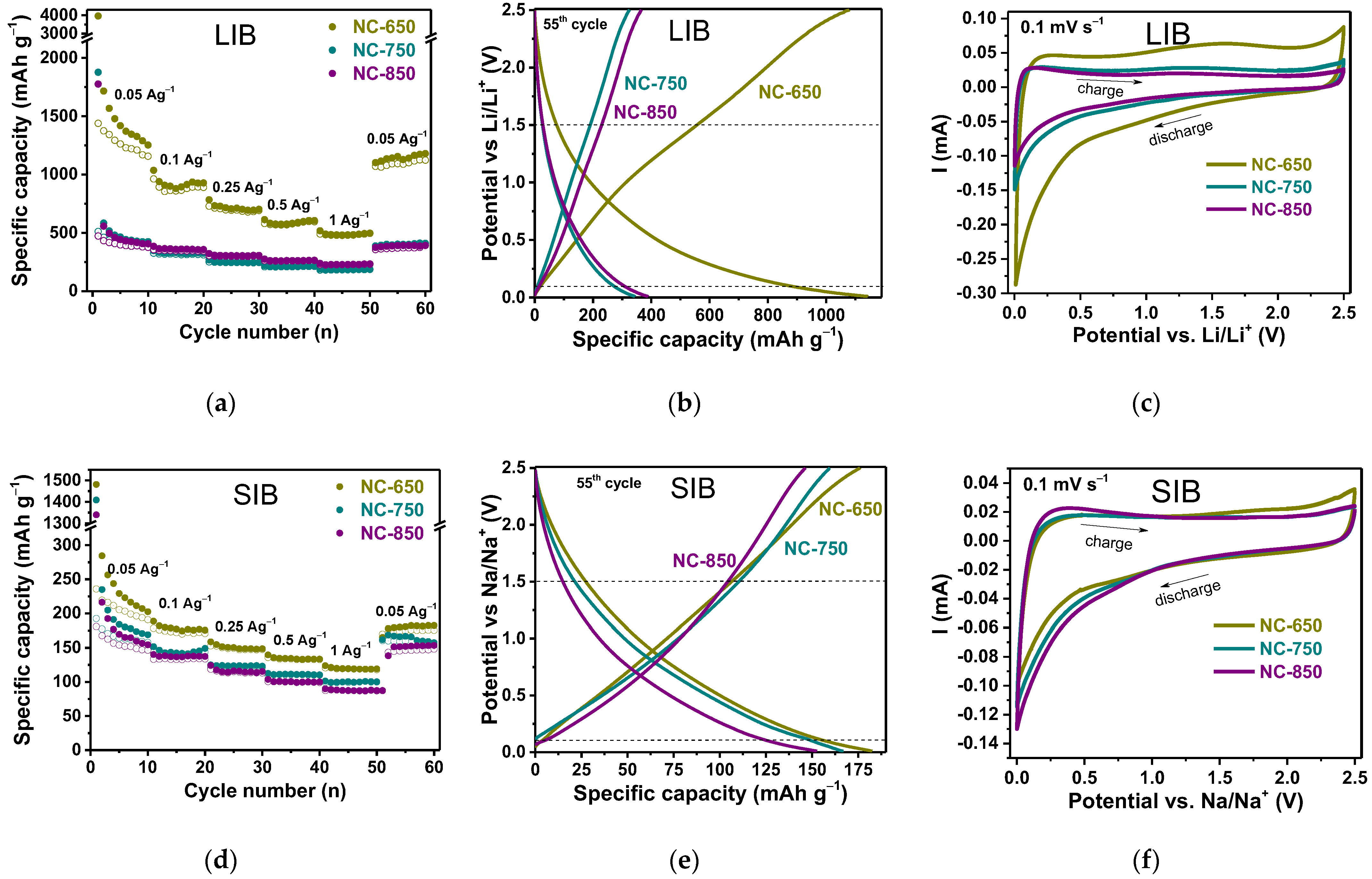
The investigation of the electrochemical properties of the NC samples as electrode materials for LIBs and SIBs was carried out using galvanostatic tests of half-cells with metal counter electrodes at various current densities for 60 cycles, as shown in Figure 5a,d. The initial specific discharge capacity, measured at a current density of 0.05 A·g−1, decreases from 3960 to 1775 mA·h·g−1 in the LIBs and from 1481 to 1328 mA·h·g−1 in the SIBs, with an increase in synthesis temperature from 650 to 850 °C. The initial specific charge capacities for NC-650, NC-750, and NC-850 are 1438, 511, and 472 mA·h·g−1 in LIBs and 238, 192, and 181 mA·h·g−1 in SIBs, respectively. The capacity drop in the first cycle is greater for the NC-650 electrode and less for the NC-750 and NC-850 electrodes. Initial coulombic efficiency (CE) is relatively low and amounts to 16–36%. After 10 cycles, at the same current density, the CE is 92% for the LIBs and 93–95% for the SIBs. The higher irreversible capacity in the first cycles is attributed to the formation of the electrochemically stable solid electrolyte interface (SEI) film on the electrode material surface and the degradation of electrolytes [46]. In later cycles, the charge–discharge curves almost completely overlap, indicating the stability of the electrodes and an SEI film. The high capacity loss in the first cycle is a consequence of the large specific surface areas of the samples, which, at the same time, contributes to their high reversible capacity. Loss of capacitance is a disadvantage of these materials, and the formation and control of the SEI layer at the carbon–electrolyte interface is one of the most important problems of LIBs and SIBs. Choosing the right electrolyte and additives that can help control the formation of the protective SEI layer may be one solution to this problem. A recent report of extremely high initial Coulomb efficiency in the first cycle of high-surface-area carbon using an ether-based electrolyte can provide guidance for further improvement [47].
The NC electrodes show outstanding cycling and rate performances in LIBs and SIBs. NC-650 demonstrates high capacity in both LIBs and SIBs at all current densities. In LIBs, its reversible specific capacities are 1158, 890, 695, 577, and 489 mA·h·g−1 at current densities of 0.05, 0.1, 0.25, 0.5, and 1 A·g−1, respectively. In SIBs, the reversible specific capacity values are 182, 177, 147, 137, and 120 mA·h·g−1 at the same current densities, which is lower than those in LIBs. The lower diffusion coefficient of Na+ ions, higher standard potential compared with Li+ ions and limited interlayer spacing for large Na+ ions lead the lower reversible capacity in SIB. The samples synthesized at higher temperatures have much lower LIB capacity values, from 405 to 180 mA·h·g−1 for NC-750 and from 1158 to 489 mA·h·g−1 for NC-850 with an increase in the current density from 0.05 to 1 A·g−1 compared with NC-650 (Figure 5a, Table 1). In the case of SIBs, the NC-750 and NC-850 samples also demonstrate slightly lower capacities ranging from 165 to 102 mA·h·g−1 and from 150 to 86 mA·h·g−1, respectively (Figure 5d, Table 1). For LIBs and SIBs, the discharge and charge capacity curves of samples can become almost reversible during charge after 60 cycles, achieving CEs of 92–100%. The extremely high capacity of NC-650 in LIBs compared with the capacity in SIBs and the capacities of other electrodes can be explained by the extended interlayer space and the presence of atomic defects in this sample, through which small Li+ ions can penetrate into the internal pores. Figure 5b,e demonstrate the charge–discharge curves for all the tested samples at 0.05 A·g−1 during the 55th cycle. Comprehensive studies show that the storage of lithium and sodium ions in NC electrodes has similar accumulation mechanisms, which include adsorption on the carbon material surface at ~1.0 V, interlayer intercalation, and pore filling at potentials below ~0.1 V [48,49,50,51]. All the samples have very similar charge–discharge profiles in both LIBs and SIBs. The high contribution of the slope region in the potential range from ca. 0.1 to 1.0 V to the charge–discharge profiles indicates that the main mechanism of both lithium and sodium storage is adsorption on the carbon surface. The intercalation process is also observed but is not the determining process, which can be suggested to be due to the disordered structure of thin interconnected carbon walls. The highest specific LIB and SIB capacities are observed for NC-650, mainly due to an increase in the slope region capacity impact, in which the highest surface area and open pore volume act as new adsorption centers for Li+ or Na+ ions. Moreover, the small plateau region at ~1.5 V is observed for the NC-650 electrode, and it can be related to the electrochemical reaction of lithium and sodium ions with functional groups in porous carbon materials [52]. In addition, the NC-650 sample demonstrates a longer intercalation-related plateau region, which contributes ~320 mA·h·g−1 (28%) to the total lithium storage capacity and ~30 mA·h·g−1 (17%) to the total sodium storage capacity.
CV measurements were carried out after the completion of 60 cycles at a scan rate of 0.1 mV·s−1 (Figure 5c,f). The CV curves of the NC samples have a similar shape, which is typical for carbon materials. The quasi-rectangular shape of the CV curves indicates the capacitive behavior of the NC materials. The redox peaks at ca. 0.1/0.2 V vs. Li/Li+ or Na/Na+ are attributed to the intercalation/extraction of lithium or sodium between graphitic layers. Wide peaks at 0.7/1.8 V vs. Li/Li+ or Na/Na+ can be associated with the reaction of alkali-metal ions with oxygen- or nitrogen-containing functional groups [53]. Among all the electrodes, NC-650 has a CV shape closer to a rectangular shape and the most intensive peaks at 0.1/0.2 and 0.7/1.8 V. In addition, NC-650 in LIBs shows the largest area limited by the CV curve, implying the best charge storage performance. This result is directly related to the specific surface of the material and the pore volume, which directly affect the number of electrochemically active centers and the accumulation of Li+ ions rather than Na+ ions. The samples synthesized at higher temperatures have lower numbers of these active centers for alkaline metal adsorption sites than NC-650. Obviously, the NC-650 material has excellent capability, reversibility, and stability in both LIBs and SIBs.
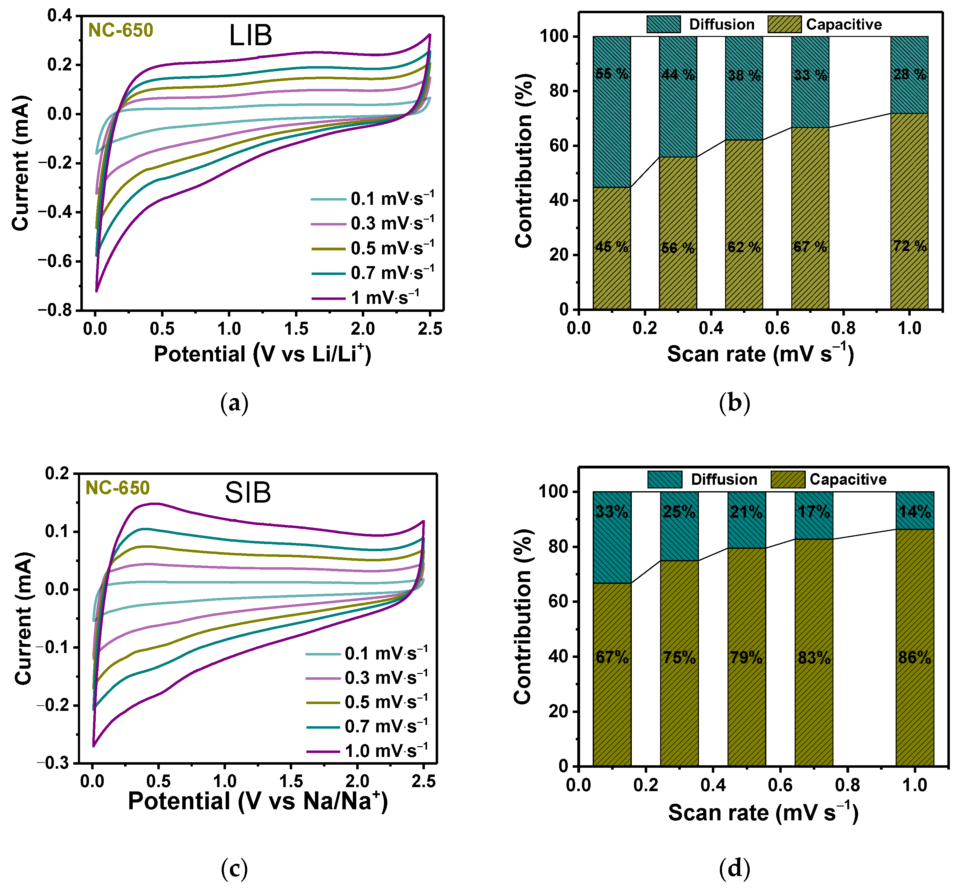
Since NC-650 demonstrates excellent performance in both LIBs and SIBs, the electrochemical kinetics of the NC-650 electrode with respect to lithium and sodium ion electrochemical storage were examined using CV measurements at various scanning rates from 0.1 to 1.0 mV·s−1 (Figure 6a,c). The contribution of pseudocapacitive behavior and diffusion-controlled processes to the electrochemical storage process could be quantitatively estimated through the following equation: i(v) = k1v + k2v1/2, where i(v) is the total current, k1v is the current from a surface-controlled charge storage process (capacitive behavior), and k2v1/2 is the current from a diffusion-controlled process (diffusion), respectively. Figure 6b,d show the capacitive and diffusion contributions to the total capacity of NC-650 in LIBs and SIBs at different sweep rates. In LIBs, the capacitance-driven contribution is 45% at 0.1 mV·s−1, and it gradually increases to 72% with an increase in the scan rate to 1.0 mV·s−1 (Figure 6b). Figure 6c shows that the capacitive contribution to the SIB capacity is 67% at a sweep rate of 0.1 mV·s−1, and, with an increase in the scan rate to 1.0 mV·s−1, the diffusion contribution is depressed, while the capacitive contribution is enhanced to 86% (Figure 6d). These results demonstrate that storing both Li+ and Na+ ions in the highly porous NC-650 material is dominated by the capacitive process, indicating fast electrochemical reaction kinetics and, as a result, excellent rate performance. However, in the case of Li+ ion diffusion-controlled capacity, the contribution is much larger than for Na+ ions. The discharge–charge and CV curves of the NC-750 and NC-850 electrodes are very similar to the NC-650 electrode, but lower capacity values were obtained for these samples. Since the drop in capacity with an increase in the synthesis temperature does not strongly depend on the current density, it can be assumed that in NC-750 and NC-850, as in NC-650, fast charge processes and the capacitive contribution predominated.
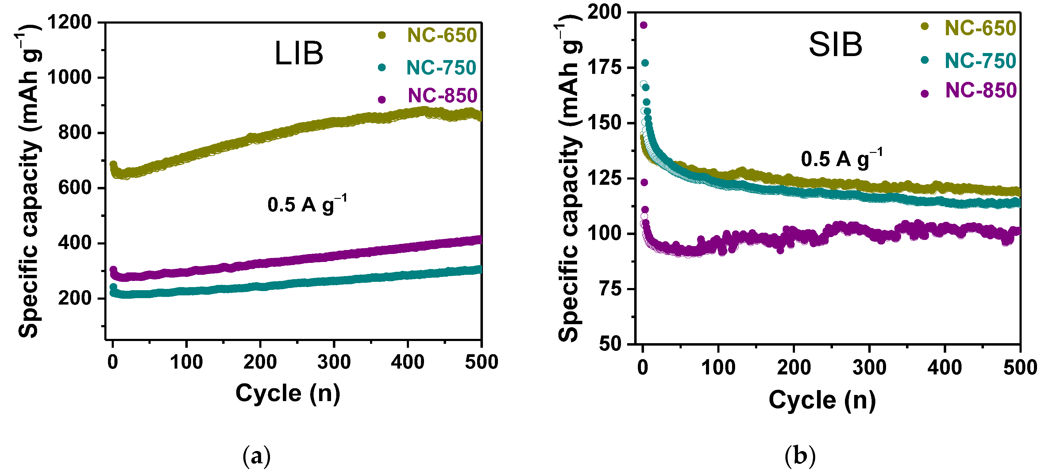
The long-term cycling in LIBs and SIBs at a current density of 0.5 A·g−1 shows excellent capacity retention over 500 cycles for all the NC samples (Figure 7a,b). At the same time, the CE remains at the level of ~100% in all cycles. In addition to this, there is a gradual increase in LIB capacity from 658 to 878 mA·h·g−1 for NC-650, from 213 to 303 mA·h·g−1 for NC-750, and from 280 to 418 mA·h·g−1 for NC-850 after 500 operation cycles (Figure 7a). Such increases in specific capacity was previously observed for carbon materials and can be related to the activation of previously inaccessible pores and the development of vacancies [54], or the formation of an electrochemically stable solid electrolyte interface (SEI) film [46]. All these factors increase the number of intercalated or adsorbed Li+ ions. In contrast to the LIB test, the long-cycle performances of the NC samples in the SIB test (Figure 7b) show a slight decrease in capacity after 500 operation cycles. This phenomenon is commonly attributed to the incomplete stabilization of the SEI layer [55] and/or to the capture of Na+ ions between carbon layers and in defective places, which cannot be released during the subsequent discharge process [56].
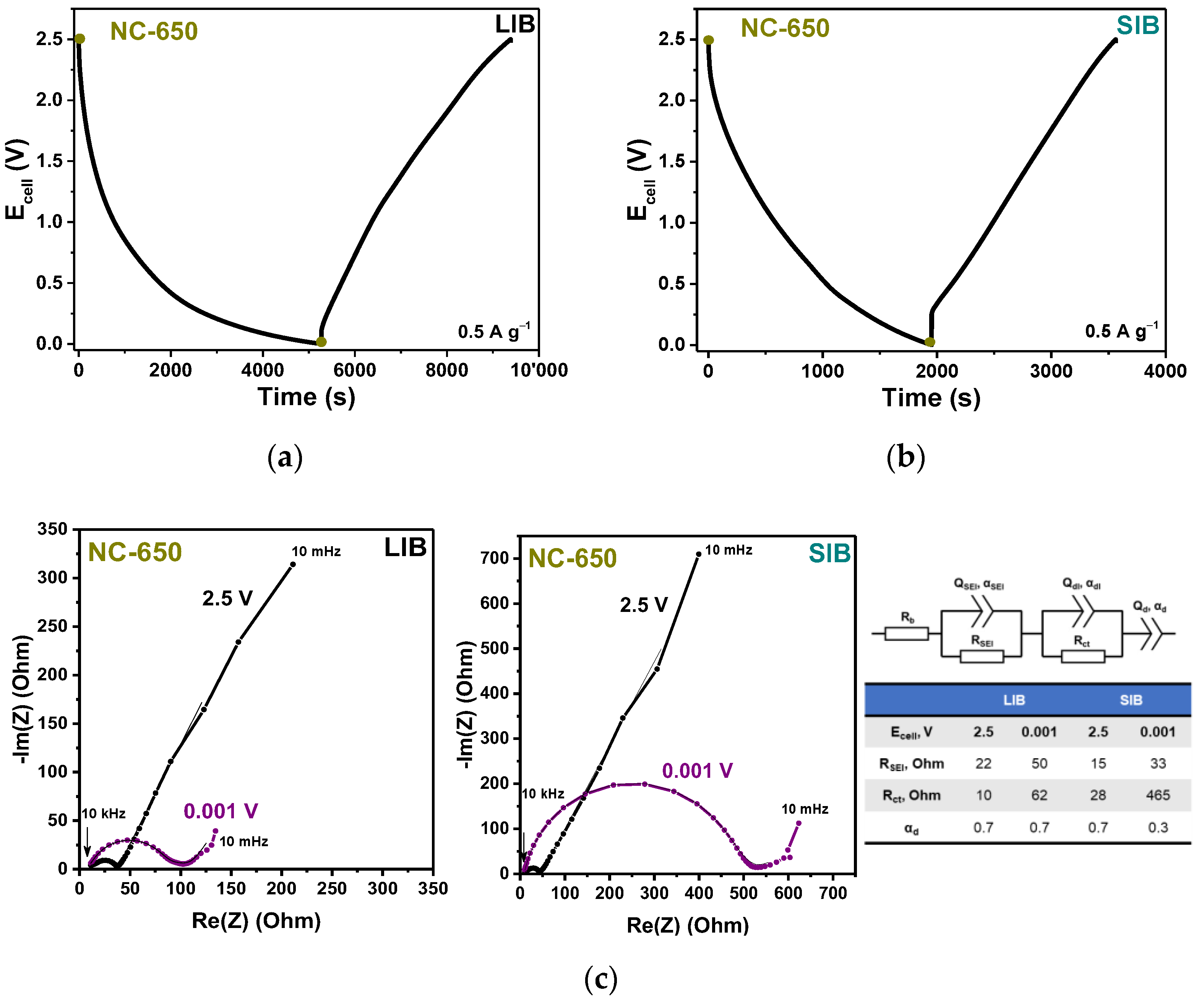
The discharge–charge test in the fourth cycle (Figure 8a,b) for the CN-650 electrode shows that the fully discharging (charging) of the batteries from 2.5 V at a constant current density of 0.5 A·g−1 to 0.001 V occurs for 1 h 28 min in LIBs, which is 2.7 times faster than in SIBs. At the same time, the LIB system has a 4.5 times higher capacity and energy density than the SIB system, but the power density of 270 W·kg−1 for SIBs is comparable with the 392 W·−kg−1 for LIBs. EIS spectra were measured after five cycles at different potentials of 2.5 V and 0.001 V during the discharge–charge tests (shown by points in Figure 8a,c) to gain insights into the electrochemical Li+ and Na+ storage behaviors of NC-600 (Figure 8c). An alternating voltage with an amplitude of 5 mV in the frequency range from 10 mHz to 10 kHz was applied. The Nyquist plots are composed of two regions: the semicircle in the middle-to-high frequency corresponds to the interfacial impedance and the charge transfer resistance, while the straight line in the low frequency relates to the diffusion of Li+ or Na+ in the electrode material. The impedance is fitted by an equivalent circuit, which includes ohmic internal resistance Rb in the high frequency region, resistance RSEI and constant phase element QSEI referring to an SEI layer, charge transfer resistance Rct and constant phase element Qdl describing the formation of an electric double layer, and a constant phase element Qd related to low-frequency processes of diffusion and charge accumulation at the electrode interface (Figure 8c) [57,58,59]. At a potential of 2.5 V, the NC-650 electrode exhibits the impedance spectrum, which has very similar behavior to that of an ideally polarized blocking electrode, with a constant phase element exponent parameter close to 1. It means the formation of an electric double-layer and the absence of Li+ and Na+ intercalation at this potential. SEI resistance RSEI and charge transfer resistance Rct increase with a decreasing potential to 0.001 for both LIB and SIB cells. This indicates the changes in the structure and composition of the fully lithiated or sodiated SEI layers and electrode bulk. The highest Rct value for fully sodiated NC-650 means that the insertion of Na+ ions induces stronger changes in the structure of the electrode than Li+ ions. In the low-frequency region, the slope of the straight line (an exponent parameter αd of 0.7) remains unchanged for the LIB cell, but in the case of the SIB cell, αd drops to 0.3 as a result of the decreasing potential. This behavior is attributed to deterioration in the diffusion of sodium ions due to changes in the composition of the electrode material.
The diffusion coefficients of lithium and sodium ions in NC-650 were estimated using theoretical processing of the low-frequency linear region of the EIS spectra corresponding to the solid-state diffusion of lithium ions in a material [60]. The Warburg coefficient was obtained via linear approximation of the dependence of the imaginary part of the impedance −Zim(ω) on ω−0.5, where ω is the cycle frequency of the applied AC voltage. The approximation was performed in the frequency range from 10 to 50 mHz at potentials of 2.5 and 0.001 V. The obtained values of the diffusion coefficients are in the range 10−8–10−10 cm2·s−1, depending on the charge state of the battery. These values are comparable for lithium and sodium ions and correlate well with the diffusion coefficient of lithium ions in mesocarbon microbeads and disordered and graphitized carbons [61,62]. However, the values are two orders of magnitude higher than the diffusion coefficient of lithium ions in graphite of 10−12 cm2·s−1 [63,64] which may be related to the high porosity of the materials studied.

4. Discussion

Thermal decomposition of acetonitrile molecules on the surface of calcium tartrate pyrolysis products yields a nitrogen-doped carbon (NC) material, where carbon atoms are mainly in the sp2-hybridized state and form highly defective curved layers. Such morphology provides the high specific surface area (358–770 m2·g–1) and high porosity (0.9–1.3 cm3·g–1) of the material, which makes it attractive for use as an anode in LIBs and SIBs. The textural characteristics as well as the concentration and chemical state of the embedded nitrogen atoms depend on the synthesis temperature (Table 1). It was shown that the material obtained at the lowest temperature (NC-650) has a large surface area, is enriched with small pores (~3 nm), and contains a lower amount of nitrogen (~4 at%). Tests of the three synthesized materials in LIBs and SIBs showed the best performance of NC-650 (Figure 5a,d). Interestingly, the discharge–charge curves recorded for both electrochemical cells have similar slope shapes, which is typical for the adsorption of metal ions on carbon surfaces (Figure 5b,e). The contribution to the capacity from the intercalation process, which occurs below 0.2 V, is higher in the case of LIBs. The study of the kinetics of the electrochemical reactions carried out for the NC-650 electrode confirms the predominance of the pseudocapacitive behavior of the material in SIBs compared with LIBs (Figure 6b,d).
Since the capacitive charge storage is determined by the reactions occurring on the electrode surface, we performed model experiments to study the interactions of the synthesized materials with sodium. In these experiments, thermally evaporated sodium was deposited onto the samples in the vacuum chamber of the spectrometer, which prevented their interaction with air molecules. The three studied samples were placed on one substrate to maintain the same sodium deposition conditions. In actuality, the XPS analysis revealed about 4 at% of Na on the surfaces of all the samples, while concentrations of nitrogen and oxygen did not change relative to the initial samples. Changes in the electronic state of carbon and nitrogen as a result of sodium deposition were monitored using NEXAFS spectroscopy, which is sensitive to the bonding environment of the absorbing atom and can provide additional information about the structural disorder and defect states in carbon matrices.
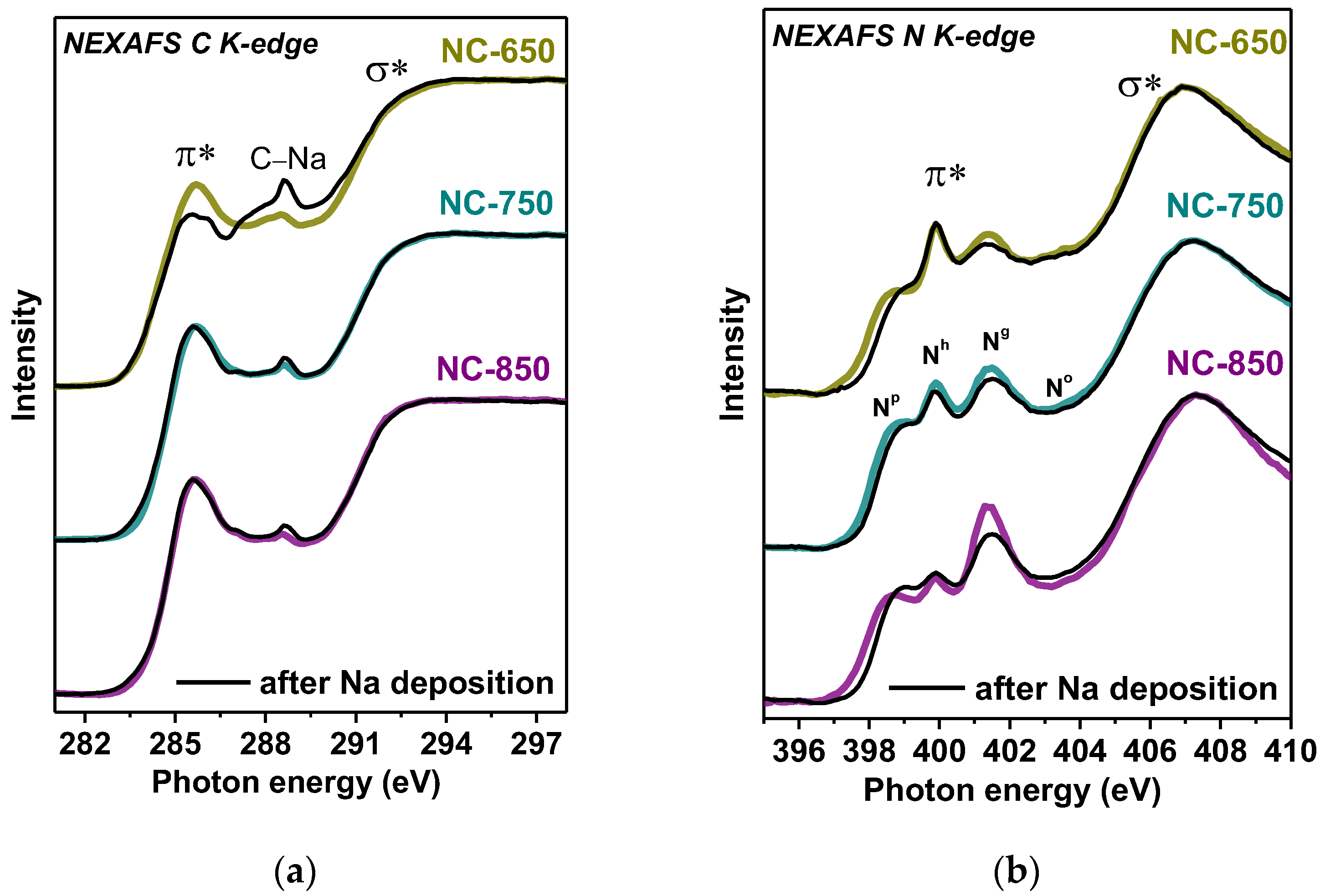
Figure 9 presents NEXAFS C K- and N K-edge spectral profiles of the samples before and after sodium deposition. The initial C K-edge spectra exhibit π* resonances at 285.4 eV and σ* resonances at 292.5 eV (Figure 9a), which are attributed to the electron transitions of 1s core electrons to unoccupied π* and σ* bands in sp2 carbon materials with aromatic graphitic-like structures [65]. A small feature located between the two resonances at 288.5 eV is due to the presence of carbon atoms covalently bonded to the functional groups [42]. Compared with the spectrum of natural graphite [40], the π* resonances have a greater width and lower intensity, which indicates that the samples consist of defective graphitic layers. The C K-edge spectrum of NC-650 has the lowest intensity of the π* resonance due to its most disordered and defective structure.
The deposition of sodium leads to a slight change in the shape of the C K-edge spectra of NC-750 and NC-850 but causes the suppression of the π* resonance intensity and enhancement of the feature at 288.5 eV (Figure 9a). A similar effect was found earlier in the NEXAFS C K-edge spectra of natural graphite and highly-oriented pyrolytic graphite (HOPG) after interaction with Li vapors [40,66]. The defective HOPG showed the most significant spectral changes, namely a decrease in the intensity of the π* resonance and an increase in the intensity of the peak located between the π* and σ* resonances. Since sodium deposition does not change the concentration of other functional groups, an increase in the intensity of the feature labeled C-Na is associated with the formation of chemical bonds between sodium and carbon.
According to the literature, the NEXAFS C K-edge spectrum of (C5H5)Na has one π* resonance at 285.9 eV corresponding to the antibonding molecular orbitals of the anion (C5H5) [67], whereas the spectrum of tetracyanoethylene after doping with thermally evaporated Na shows an increased peak in the high energy region at about 287 eV due to adsorption of Na on the edge cyano groups of the molecule [68]. The exact reason for the decrease in the π* resonance and the increase in the intensity of the peak at a higher energy is unknown; it is probable that under-coordinated carbon atoms surrounding small atomic vacancies or located at the edges of graphite domains can form covalent bonds with sodium. The Na 3s and 3px orbitals mix with the dangling C 2px orbitals, and the Na 3pz orbitals overlap with the conjugated π-electron system of graphene. This is similar to the formation of Li-C bonds in the lithiated natural graphite powder [40]. Among the studied samples, NC-650 contains the largest number of defects, which are responsible, in particular, for its large surface area. The high intensity of the C-Na feature in the NEXAFS C K-edge spectrum after the interaction of the sample with sodium indicates the presence of unsaturated carbon atoms, which can be located at the edges of vacancies and graphene domains. Indeed, a similar model study of the interaction between holey graphene and lithium detected an increased intensity between the π* and σ* resonances of the C K-edge spectrum [69]. Vacancies formed in graphitic layers as a result of synthesis can increase in size during repeated charge–discharge cycling of an electrochemical cell. In-plane holes are additional channels for the interlayer intercalation of lithium ions, which ensures the continuous growth of the specific capacity of the carbon-containing material with cycles [54,70]. This behavior was observed during the long-term tests of all the studied samples in LIBs, and the largest capacity gain was achieved with the NC-650 electrode (Figure 7).
The NEXAFS N K-edge spectra of NC-650, NC-750, and NC-850 contain four π* resonances at 398.7, 399.9, 401.4, and 403.0 eV (Figure 9b), consistent with the XPS data (Figure 4d). These resonances correspond to pyridinic (Np), hydrogenated pyridinic (Nh), graphitic (Ng), and oxygenated nitrogen (No), respectively. After sodium deposition, the N K-spectra show a decrease in the intensities of the Np and Ng peaks. Similar spectral changes were found for an N-doped carbon material after the thermal deposition of lithium, and quantum chemical calculations revealed that Li prefers to bind with the pyridinic nitrogen [27].
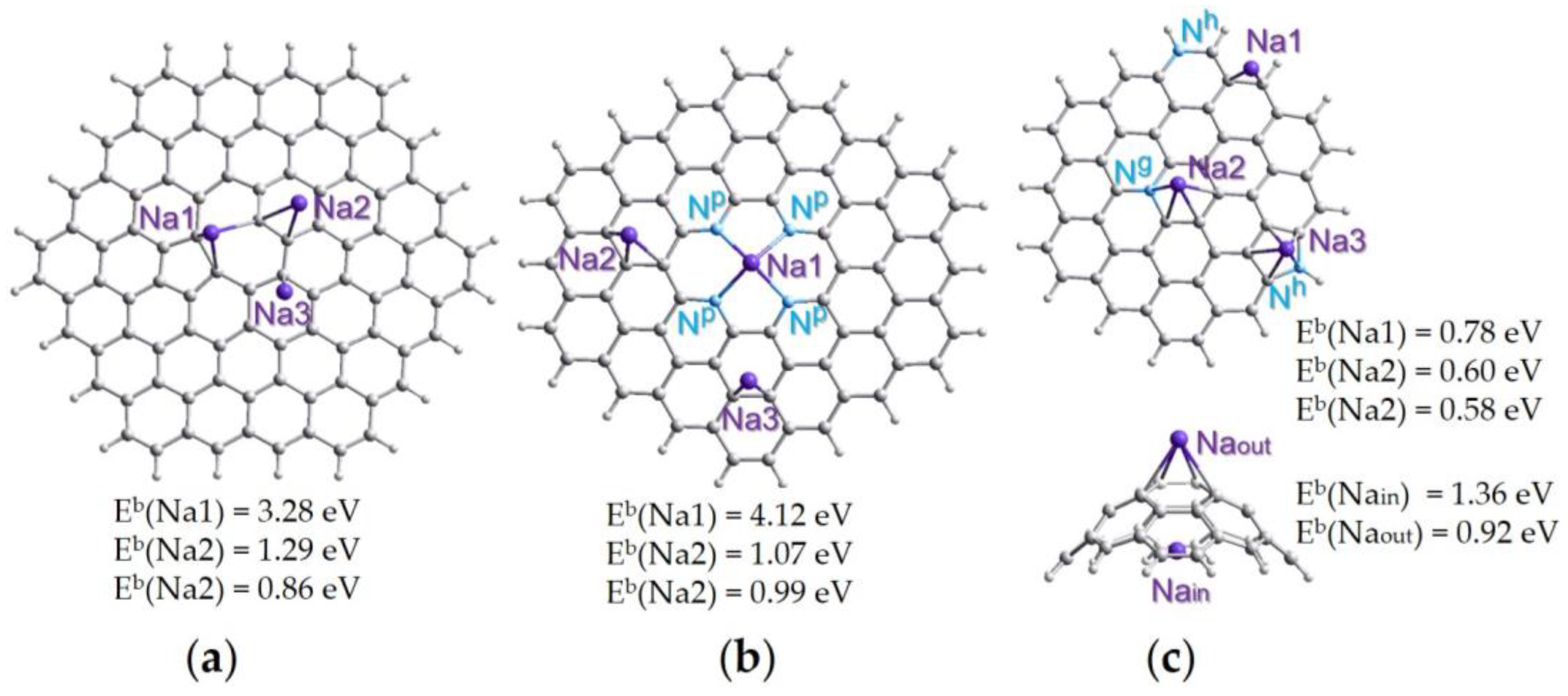
To elucidate the effects of the defects present in NC layers on the adsorption of sodium, we performed the DFT calculations of graphene fragments with monovacancy (Figure 10a), with double vacancy terminated with four pyridinic Np (Figure 10b), and containing graphitic Ng in the central part and two hydrogenated Nh at the edges (the top model in Figure 10c). The formation of N-terminated double vacancies (N4-sites) in graphene layers grown using the thermal decomposition of acetonitrile vapor was established using extended X-ray absorption fine structure spectroscopy in [71]. Since the layers of our materials deposited on the template nanoparticles are highly curved, a graphene-like cap containing two pentagons was also considered (the bottom model in Figure 10c). Near the defects, from one to two Na atoms were located.
The calculations show that sodium strongly interacts with the four nitrogen atoms of the double vacancy (Figure 10b) and three-edged carbon atoms of the monovacancy (Figure 10a). The corresponding binding energies are 4.12 and 3.28 eV. High values mean that these defects are irreversibly trapping sodium. However, the occupied defects contribute to the addition of the next sodium atoms in their vicinity. The binding energies for the second (Na2) and third (Na3) deposited sodium atoms are 1.29–0.86 eV (Figure 10a,b). Similar values were obtained for the interaction of sodium with the inner surface (1.36 eV) and outer surface (0.92 eV) of curved graphene (the bottom model in Figure 10c). All the above energies are within the potential window in which the studied electrode materials reversibly store sodium. Sodium prefers to sit above a hexagon containing an Ng atom or pentagon containing an Nh atom, but not above a hexagon with Nh (the top model in Figure 10c). However, the latter defect produces a gain in sodium adsorption at the edge of the graphene domain. Therefore, all the considered defects improve the sodium interaction with the graphitic surface, which in the case of an ideal lattice is energetically unfavorable [72]. Similar conclusions were made from DFT calculations of graphene models with divacancies and Stone–Wales defects [4,73].
The bonding of sodium to the under-coordinated carbon atom of the monoatomic vacancy explains the increased intensity of the C-Na feature in the NEXAFS C K-edge spectra of the sodiated samples (Figure 9a). The absence of a change in the electronic state of Nh atoms after sodium deposition (Figure 9b) may indicate that most of these nitrogen atoms are located in hexagons since calculations do not show a direct interaction between nitrogen and sodium in this case. Based on the calculation results, we also conclude that reversible reactions, which give the contribution in the slope regions of the charge–discharge profiles of the NC electrodes (Figure 5e), are due to the adsorption of sodium near topological defects, Ng and edge Nh atoms, and pre-sodiated vacancy defects. The same conclusion can be drawn for lithium.

5. Conclusions

In summary, the composition and structure of nitrogen-doped carbon (NC) materials synthesized using acetonitrile and calcium tartrate can be tuned via the synthesis temperature ranging from 650 to 850 °C. Synthesis results in the inclusion of 4–6 at% nitrogen mainly in the form of pyridinic N, hydrogenated N, and graphitic N. The sample grown at 650 °C (NC-650) had the highest concentration of small pores of less than 5 nm in size, the largest surface area of 770 m2·g−1, and the highest pore volume of 1.3 cm3·g−1. In addition, in this sample, the lowest total nitrogen content, the lowest fraction of graphitic N, and a greater number of defects in the graphitic structure were found. The electrochemical testing of the synthesized NC materials revealed a high reversible capacity of 86–120 mA·h·g−1 in SIBs and 223–489 mA·h·g−1 in LIBs at a current density of 1 A·g−1 and potentials below 1 V vs. Na/Na+ and Li/Li+, as well as their stabilities during long-term cycling. The NC electrodes exhibited a capacitive character in the storage of alkali metals, especially in the case of sodium, which is related to their reversible adsorption on the surface of NC. Lithium diffusion processes contribute more to electrode capacity than sodium ones due to the ability of lithium to intercalate into the interlayer spaces of graphitic materials. The presence on the surface of NC-650 of a large number of sites capable to adsorb metal ions ensured the highest capacity values of 489–1158 mA·h·g−1 in SIBs and 120–182 mA·h·g−1 in LIBs at current densities of 1.0–0.05 A·g−1. The in situ NEXAFS experiments and DFT calculations revealed that nitrogen and carbon atoms located at the edges of vacancy defects are strongly bonded to Na and can explain the high irreversible capacities of the NC electrodes in the first cycles. The adsorption of Na or Li in the regions around the sodiated or lithiated vacancy defects, topological defects, and hydrogenated and graphitic nitrogen groups can contribute to the slope regions of the charge–discharge curves in a wide range of potentials. These results provide new insights for the design and fabrication of NC electrode materials for improved storage of Li+ and Na+ ions. They shed light on the nature of the defects, which could enable efficient sodium storage in SIB anodes.

Author Contributions

Conceptualization, Y.V.F.; writing—original draft, Y.V.F., E.V.S., A.A.V. and S.G.S.; project administration, Y.V.F.; methodology, E.V.S., A.A.M. and A.V.O.; investigation, E.V.S., A.A.V., S.G.S., M.A.G., V.I.S., E.A.M., A.A.M. and L.G.B.; formal analysis, M.A.G., E.A.M., A.A.M. and A.V.O.; resources, A.A.M.; validation, A.V.O.; L.G.B.; supervision, A.V.O.; writing—review and editing, L.G.B. All authors have read and agreed to the published version of the manuscript.

Funding

This research was funded by the Russian Science Foundation (grant 19-73-10068). The kinetic study was supported by the Ministry of Science and Higher Education of the Russian Federation (project 121031700314-5). A.A.M. acknowledges BMBF (grant no. 05K19KER).

Institutional Review Board Statement

Not applicable.

Informed Consent Statement

Not applicable.

Data Availability Statement

Not applicable.

Acknowledgments

The authors thank A. V. Ischenko for the TEM data, E.V. Lobiak for the N2 adsorption measurements, and the Helmholtz-Zentrum Berlin für Materialien und Energie for the allocation of beamtime for the XPS and NEXAFS measurements and support within the Russian German Laboratory at BESSY II.

Conflicts of Interest

The authors declare no conflict of interest.

References

  1. Cao, Y.; Xiao, L.; Sushko, M.L.; Wang, W.; Schwenzer, B.; Xiao, J.; Nie, Z.; Saraf, L.V.; Yang, Z.; Liu, J. Sodium Ion Insertion in Hollow Carbon Nanowires for Battery Applications. Nano Lett. 2012, 12, 3783–3787. [Google Scholar] [CrossRef]
  2. Olsson, E.; Cottom, J.; Au, H.; Guo, Z.; Jensen, A.C.S.; Alptekin, H.; Drew, A.J.; Titirici, M.M.; Cai, Q. Elucidating the Effect of Planar Graphitic Layers and Cylindrical Pores on the Storage and Diffusion of Li, Na, and K in Carbon Materials. Adv. Funct. Mater. 2020, 30, 1908209. [Google Scholar] [CrossRef] [Green Version]
  3. Karatrantos, A.; Cai, Q. Effects of Pore Size and Surface Charge on Na Ion Storage in Carbon Nanopores. Phys. Chem. Chem. Phys. 2016, 18, 30761–30769. [Google Scholar] [CrossRef] [Green Version]
  4. Datta, D.; Li, J.; Shenoy, V.B. Defective Graphene as a High-Capacity Anode Material for Na- and Ca-Ion Batteries. ACS Appl. Mater. Interfaces 2014, 6, 1788–1795. [Google Scholar] [CrossRef] [PubMed]
  5. Tsai, P.C.; Chung, S.C.; Lin, S.K.; Yamada, A. Ab Initio Study of Sodium Intercalation into Disordered Carbon. J. Mater. Chem. A 2015, 3, 9763–9768. [Google Scholar] [CrossRef]
  6. Matei Ghimbeu, C.; Górka, J.; Simone, V.; Simonin, L.; Martinet, S.; Vix-Guterl, C. Insights on the Na+ Ion Storage Mechanism in Hard Carbon: Discrimination between the Porosity, Surface Functional Groups and Defects. Nano Energy 2018, 44, 327–335. [Google Scholar] [CrossRef]
  7. Nie, W.; Cheng, H.; Liu, X.; Sun, Q.; Tian, F.; Yao, W.; Liang, S.; Lu, X.; Zhou, J. Surface Organic Nitrogen-Doping Disordered Biomass Carbon Materials with Superior Cycle Stability in the Sodium-Ion Batteries. J. Power Sources 2022, 522, 230994. [Google Scholar] [CrossRef]
  8. Liu, T.; Li, X. Biomass-Derived Nanostructured Porous Carbons for Sodium Ion Batteries: A Review. Mater. Technol. 2019, 34, 232–245. [Google Scholar] [CrossRef]
  9. Sun, N.; Liu, H.; Xu, B. Facile Synthesis of High Performance Hard Carbon Anode Materials for Sodium Ion Batteries. J. Mater. Chem. A 2015, 3, 20560–20566. [Google Scholar] [CrossRef]
  10. Liu, H.; Jia, M.; Yue, S.; Cao, B.; Zhu, Q.; Sun, N.; Xu, B. Creative Utilization of Natural Nanocomposites: Nitrogen-Rich Mesoporous Carbon for a High-Performance Sodium Ion Battery. J. Mater. Chem. A 2017, 5, 9572–9579. [Google Scholar] [CrossRef]
  11. Gaddam, R.R.; Farokh Niaei, A.H.; Hankel, M.; Searles, D.J.; Kumar, N.A.; Zhao, X.S. Capacitance-Enhanced Sodium-Ion Storage in Nitrogen-Rich Hard Carbon. J. Mater. Chem. A 2017, 5, 22186–22192. [Google Scholar] [CrossRef]
  12. Vu, N.H.; Le, H.T.T.; Hoang, V.H.; Dao, V.D.; Huu, H.T.; Jun, Y.S.; Im, W. Bin Highly N-Doped, H-Containing Mesoporous Carbon with Modulated Physicochemical Properties as High-Performance Anode Materials for Li-Ion and Na-Ion Batteries. J. Alloys Compd. 2021, 851, 156881. [Google Scholar] [CrossRef]
  13. Samdani, J.S.; Tran, T.N.; Kang, T.H.; Lee, B.J.; Jang, Y.H.; Yu, J.S.; Shanmugam, S. The Identification of Specific N-Configuration Responsible for Li-Ion Storage in N-Doped Porous Carbon Nanofibers: An Ex-Situ Study. J. Power Sources 2021, 483, 229174. [Google Scholar] [CrossRef]
  14. Feng, X.; Bai, Y.; Zheng, L.; Liu, M.; Li, Y.; Zhao, R.; Li, Y.; Wu, C. Effect of Different Nitrogen Configurations on Sodium Storage Properties of Carbon Anodes for Sodium Ion Batteries. ACS Appl. Mater. Interfaces 2021, 13, 56285–56295. [Google Scholar] [CrossRef] [PubMed]
  15. Gao, X.; Shen, Z.; Chang, G.; Li, Z.; Zhao, H. Mechanochemistry Induced Pore Regulation and Pyridinic Nitrogen Doping in Anthracite Derived Carbon for Sodium Storage. Diam. Relat. Mater. 2022, 130, 109481. [Google Scholar] [CrossRef]
  16. Qu, Y.; Guo, M.; Zeng, F.; Zou, C.; Yuan, C.; Zhang, X.; Li, Q.; Lu, H. Synthesis of Nitrogen-Doped Porous Carbon Nanofibers as an Anode Material for High Performance Sodium-Ion Batteries. Solid State Ionics 2019, 337, 170–177. [Google Scholar] [CrossRef]
  17. Agrawal, A.; Janakiraman, S.; Biswas, K.; Venimadhav, A.; Srivastava, S.K.; Ghosh, S. Understanding the Improved Electrochemical Performance of Nitrogen-Doped Hard Carbons as an Anode for Sodium Ion Battery. Electrochim. Acta 2019, 317, 164–172. [Google Scholar] [CrossRef]
  18. Xu, K.; Li, Y.; Liu, Y.; Zhong, G.; Wang, C.; Su, W.; Li, X.; Yang, C. Na+-Storage Properties Derived from a High Pseudocapacitive Behavior for Nitrogen-Doped Porous Carbon Anode. Mater. Lett. 2020, 261, 127064. [Google Scholar] [CrossRef]
  19. Lee, H.W.; Moon, H.S.; Hur, J.; Kim, I.T.; Park, M.S.; Yun, J.M.; Kim, K.H.; Lee, S.G. Mechanism of Sodium Adsorption on N-Doped Graphene Nanoribbons for Sodium Ion Battery Applications: A Density Functional Theory Approach. Carbon 2017, 119, 492–501. [Google Scholar] [CrossRef]
  20. Kado, Y.; Soneda, Y.; Yoshizawa, N. Excellent Rate Capability of MgO-Templated Mesoporous Carbon as an Na-Ion Energy Storage Material. ECS Electrochem. Lett. 2014, 4, A22–A23. [Google Scholar] [CrossRef]
  21. Cao, B.; Liu, H.; Xu, B.; Lei, Y.; Chen, X.; Song, H. Mesoporous Soft Carbon as an Anode Material for Sodium Ion Batteries with Superior Rate and Cycling Performance. J. Mater. Chem. A 2016, 4, 6472–6478. [Google Scholar] [CrossRef]
  22. Hsieh, Y.Y.; Fang, Y.; Daum, J.; Kanakaraj, S.N.; Zhang, G.; Mishra, S.; Gbordzoe, S.; Shanov, V. Bio-Inspired, Nitrogen Doped CNT-Graphene Hybrid with Amphiphilic Properties as a Porous Current Collector for Lithium-Ion Batteries. Carbon 2019, 145, 677–689. [Google Scholar] [CrossRef]
  23. Wang, B.; Abdulla, W.A.; Wang, D.; Zhao, X.S. A Three-Dimensional Porous LiFePO4 Cathode Material Modified with a Nitrogen-Doped Graphene Aerogel for High-Power Lithium Ion Batteries. Energy Environ. Sci. 2015, 8, 869–875. [Google Scholar] [CrossRef]
  24. Ding, Y.L.; Kopold, P.; Hahn, K.; Van Aken, P.A.; Maier, J.; Yu, Y. Facile Solid-State Growth of 3D Well-Interconnected Nitrogen-Rich Carbon Nanotube-Graphene Hybrid Architectures for Lithium-Sulfur Batteries. Adv. Funct. Mater. 2016, 26, 1112–1119. [Google Scholar] [CrossRef]
  25. Fang, Y.; Hsieh, Y.Y.; Khosravifar, M.; Johnson, K.; Kwasi Adusei, P.; Kanakaraj, S.N.; Preisler, S.; Zhang, G.; Shanov, V. Lithiophilic Current Collector Based on Nitrogen Doped Carbon Nanotubes and Three-Dimensional Graphene for Long-Life Lithium Metal Batteries. Mater. Sci. Eng. B Solid-State Mater. Adv. Technol. 2021, 267, 115067. [Google Scholar] [CrossRef]
  26. Shlyakhova, E.V.; Bulusheva, L.G.; Kanygin, M.A.; Plyusnin, P.E.; Kovalenko, K.A.; Senkovskiy, B.V.; Okotrub, A.V. Synthesis of Nitrogen-Containing Porous Carbon Using Calcium Oxide Nanoparticles. Phys. Status Solidi Basic Res. 2014, 251, 2607–2612. [Google Scholar] [CrossRef]
  27. Lapteva, L.L.; Fedoseeva, Y.V.; Shlyakhova, E.V.; Makarova, A.A.; Bulusheva, L.G.; Okotrub, A.V. NEXAFS Spectroscopy Study of Lithium Interaction with Nitrogen Incorporated in Porous Graphitic Material. J. Mater. Sci. 2019, 54, 11168–11178. [Google Scholar] [CrossRef]
  28. Shlyakhova, E.V.; Okotrub, A.V.; Fedoseeva, Y.V.; Fedorovskaya, E.O.; Mel’gunova, E.A.; Mel’gunov, M.S.; Koroteev, V.O.; Makarova, A.A.; Zhou, J.; Song, H.; et al. Iron Induced Porosity of the Templated Carbon for Enhancement of Electrochemical Capacitance. Appl. Surf. Sci. 2021, 543, 148565. [Google Scholar] [CrossRef]
  29. Perdew, J.P.; Burke, K.; Ernzerhof, M. Generalized Gradient Approximation Made Simple. Phys. Rev. Lett. 1996, 77, 3865–3868. [Google Scholar] [CrossRef] [Green Version]
  30. Grimme, S.; Antony, J.; Ehrlich, S.; Krieg, H. A Consistent and Accurate Ab Initio Parametrization of Density Functional Dispersion Correction (DFT-D) for the 94 Elements H-Pu. J. Chem. Phys. 2010, 132, 154104. [Google Scholar] [CrossRef]
  31. Fedoseeva, Y.V.; Shlyakhova, E.V.; Stolyarova, S.G.; Vorfolomeeva, A.A.; Grebenkina, M.A.; Makarova, A.A.; Shubin, Y.V.; Okotrub, A.V.; Bulusheva, L.G. Brominated Porous Nitrogen-Doped Carbon Materials for Sodium-Ion Storage. Batteries 2022, 8, 114. [Google Scholar] [CrossRef]
  32. Liu, W.; Low, N.; Feng, B.; Wang, G.; da Costa, J.C.D. Calcium Precursors for the Production of CaO Sorbents for Multicycle CO2 Capture. Environ. Sci. Technol. 2010, 44, 841–847. [Google Scholar] [CrossRef] [PubMed]
  33. Asanov, I.P.; Asanova, T.I.; Bulusheva, L.G.; Shlyakhova, E.V.; Okotrub, A.V.; Flahaut, E. Thermal Decomposition of Co-Doped Calcium Tartrate and Use of the Products for Catalytic Chemical Vapor Deposition Synthesis of Carbon Nanotubes. J. Phys. Chem. C 2012, 116, 343–351. [Google Scholar] [CrossRef]
  34. Nishchakova, A.D.; Grebenkina, M.A.; Shlyakhova, E.V.; Shubin, Y.V.; Kovalenko, K.A.; Asanov, I.P.; Fedoseeva, Y.V.; Makarova, A.A.; Okotrub, A.V.; Bulusheva, L.G. Porosity and Composition of Nitrogen-Doped Carbon Materials Templated by the Thermolysis Products of Calcium Tartrate and Their Performance in Electrochemical Capacitors. J. Alloys Compd. 2021, 858, 158259. [Google Scholar] [CrossRef]
  35. Han, M.L.; Wei, X.L.; Zhang, J.C.; Liu, Y.; Tang, X.; Li, P.; Liu, Z.Y. Influence of Structural Damage on Evaluation of Microscopic Pore Structure in Marine Continental Transitional Shale of the Southern North China Basin: A Method Based on the Low-Temperature N2 Adsorption Experiment. Pet. Sci. 2022, 19, 100–115. [Google Scholar] [CrossRef]
  36. Ferrari, A.C.; Meyer, J.C.; Scardaci, V.; Casiraghi, C.; Lazzeri, M.; Mauri, F.; Piscanec, S.; Jiang, D.; Novoselov, K.S.; Roth, S.; et al. Raman Spectrum of Graphene and Graphene Layers. Phys. Rev. Lett. 2006, 97, 187401. [Google Scholar] [CrossRef] [Green Version]
  37. Cançado, L.G.; Pimenta, M.A.; Neves, B.R.A.; Dantas, M.S.S.; Jorio, A. Influence of the Atomic Structure on the Raman Spectra of Graphite Edges. Phys. Rev. Lett. 2004, 93, 247401. [Google Scholar] [CrossRef]
  38. Hoekstra, J.; Beale, A.M.; Soulimani, F.; Versluijs-Helder, M.; Van De Kleut, D.; Koelewijn, J.M.; Geus, J.W.; Jenneskens, L.W. The Effect of Iron Catalyzed Graphitization on the Textural Properties of Carbonized Cellulose: Magnetically Separable Graphitic Carbon Bodies for Catalysis and Remediation. Carbon 2016, 107, 248–260. [Google Scholar] [CrossRef]
  39. Vasquez, R.P. Highly Oriented Pyrolytic Graphite by XPS. Surf. Sci. Spectra 1992, 1, 238–241. [Google Scholar] [CrossRef]
  40. Lapteva, L.L.; Fedoseeva, Y.V.; Gevko, P.N.; Smirnov, D.A.; Gusel’nikov, A.V.; Bulusheva, L.G.; Okotrub, A.V. X-ray Spectroscopy Study of Lithiated Graphite Obtained by Thermal Deposition of Lithium. J. Struct. Chem. 2017, 58, 1173–1179. [Google Scholar] [CrossRef]
  41. Arrigo, R.; Hävecker, M.; Wrabetz, S.; Blume, R.; Lerch, M.; McGregor, J.; Parrott, E.P.J.; Zeitler, J.A.; Gladden, L.F.; Knop-Gericke, A.; et al. Tuning the Acid/Base Properties of Nanocarbons by Functionalization via Amination. J. Am. Chem. Soc. 2010, 132, 9616–9630. [Google Scholar] [CrossRef] [PubMed]
  42. Fedoseeva, Y.V.; Pozdnyakov, G.A.; Okotrub, A.V.; Kanygin, M.A.; Nastaushev, Y.V.; Vilkov, O.Y.; Bulusheva, L.G. Effect of Substrate Temperature on the Structure of Amorphous Oxygenated Hydrocarbon Films Grown with a Pulsed Supersonic Methane Plasma Flow. Appl. Surf. Sci. 2016, 385, 464–471. [Google Scholar] [CrossRef]
  43. Desimoni, E.; Casella, G.I.; Cataldi, T.R.I.; Malitesta, C. A Comparison of Some Asymmetrical Line Shapes for XPS Data Analysis. J. Electron Spectros. Relat. Phenomena 1989, 49, 247–261. [Google Scholar] [CrossRef]
  44. Bulusheva, L.G.; Okotrub, A.V.; Fedoseeva, Y.V.; Kurenya, A.G.; Asanov, I.P.; Vilkov, O.Y.; Koós, A.A.; Grobert, N. Controlling Pyridinic, Pyrrolic, Graphitic, and Molecular Nitrogen in Multi-Wall Carbon Nanotubes Using Precursors with Different N/C Ratios in Aerosol Assisted Chemical Vapor Deposition. Phys. Chem. Chem. Phys. 2015, 17, 23741–23747. [Google Scholar] [CrossRef] [PubMed] [Green Version]
  45. Scardamaglia, M.; Struzzi, C.; Aparicio Rebollo, F.J.; De Marco, P.; Mudimela, P.R.; Colomer, J.F.; Amati, M.; Gregoratti, L.; Petaccia, L.; Snyders, R.; et al. Tuning Electronic Properties of Carbon Nanotubes by Nitrogen Grafting: Chemistry and Chemical Stability. Carbon 2015, 83, 118–127. [Google Scholar] [CrossRef]
  46. Jiang, Q.; Zhang, Z.; Yin, S.; Guo, Z.; Wang, S.; Feng, C. Biomass Carbon Micro/Nano-Structures Derived from Ramie Fibers and Corncobs as Anode Materials for Lithium-Ion and Sodium-Ion Batteries. Appl. Surf. Sci. 2016, 379, 73–82. [Google Scholar] [CrossRef]
  47. Saurel, D.; Orayech, B.; Xiao, B.; Carriazo, D.; Li, X.; Rojo, T. From Charge Storage Mechanism to Performance: A Roadmap toward High Specific Energy Sodium-Ion Batteries through Carbon Anode Optimization. Adv. Energy Mater. 2018, 8, 1703268. [Google Scholar] [CrossRef]
  48. Huang, S.; Li, Z.; Wang, B.; Zhang, J.; Peng, Z.; Qi, R.; Wang, J.; Zhao, Y. N-Doping and Defective Nanographitic Domain Coupled Hard Carbon Nanoshells for High. Adv. Funct. Mater. 2018, 28, 1706294. [Google Scholar] [CrossRef]
  49. Velez, V.; Ramos-Sánchez, G.; Lopez, B.; Lartundo-Rojas, L.; González, I.; Sierra, L. Synthesis of Novel Hard Mesoporous Carbons and Their Application as Anodes for Li and Na Ion Batteries. Carbon 2019, 147, 214–226. [Google Scholar] [CrossRef]
  50. Stevens, D.A.; Dahn, J.R. High Capacity Anode Materials for Rechargeable Sodium-ion Batteries. J. Electrochem. Soc. 2000, 147, 1271–1273. [Google Scholar] [CrossRef]
  51. Shi, W.; Zhang, Y.; Tian, Z.Q.; Pan, Z.; Key, J.; Shen, P.K. Low Temperature Synthesis of Polyhedral Hollow Porous Carbon with High Rate Capability and Long-Term Cycling Stability as Li-Ion and Na-Ion Battery Anode Material. J. Power Sources 2018, 398, 149–158. [Google Scholar] [CrossRef]
  52. Yu, K.; Wang, J.; Wang, X.; Liang, J.; Liang, C. Sustainable Application of Biomass By-Products: Corn Straw-Derived Porous Carbon Nanospheres Using as Anode Materials for Lithium Ion Batteries. Mater. Chem. Phys. 2020, 243, 122644. [Google Scholar] [CrossRef]
  53. Kuo, S.L.; Liu, W.R.; Kuo, C.P.; Wu, N.L.; Wu, H.C. Lithium Storage in Reduced Graphene Oxides. J. Power Sources 2013, 244, 552–556. [Google Scholar] [CrossRef]
  54. Chen, Y.; Shi, L.; Li, A.; Zhang, S.; Guo, M.; Chen, X.; Zhou, J.; Song, H. Capacity Enhancement of Porous Carbon Electrodes during Long-Term Cycling in Lithium-Ion Batteries. J. Electrochem. Soc. 2017, 164, A2000–A2006. [Google Scholar] [CrossRef]
  55. Wang, H.; Yu, W.; Shi, J.; Mao, N.; Chen, S.; Liu, W. Biomass Derived Hierarchical Porous Carbons as High-Performance Anodes for Sodium-Ion Batteries. Electrochim. Acta 2016, 188, 103–110. [Google Scholar] [CrossRef]
  56. Luo, X.F.; Yang, C.H.; Peng, Y.Y.; Pu, N.W.; Der Ger, M.; Te Hsieh, C.; Chang, J.K. Graphene Nanosheets, Carbon Nanotubes, Graphite, and Activated Carbon as Anode Materials for Sodium-Ion Batteries. J. Mater. Chem. A 2015, 3, 10320–10326. [Google Scholar] [CrossRef]
  57. Wang, C.; Appleby, A.J.; Little, F.E. Electrochemical Impedance Study of Initial Lithium Ion Intercalation into Graphite Powders. Electrochim. Acta 2001, 46, 1793–1813. [Google Scholar] [CrossRef]
  58. Vyroubal, P.; Kazda, T. Equivalent Circuit Model Parameters Extraction for Lithium Ion Batteries Using Electrochemical Impedance Spectroscopy. J. Energy Storage 2018, 15, 23–31. [Google Scholar] [CrossRef]
  59. Funabiki, A.; Inaba, M.; Ogumi, Z.A.c. Impedance Analysis of Electrochemical Lithium Intercalation into Highly Oriented Pyrolytic Graphite. J. Power Sources 1997, 68, 227–231. [Google Scholar] [CrossRef]
  60. Ho, C.; Raistrick, I.D.; Huggins, R.A. Application of A-C Techniques to the Study of Lithium Diffusion in Tungsten Trioxide Thin Films. J. Electrochem. Soc. 1980, 127, 343–350. [Google Scholar] [CrossRef]
  61. Guo, H.; Li, X.; Zhang, X.; Wang, H.; Wang, Z.; Peng, W. Diffusion Coefficient of Lithium in Artificial Graphite, Mesocarbon Microbeads, and Disordered Carbon. New Carbon Mater. 2007, 22, 7–10. [Google Scholar] [CrossRef]
  62. Chang, Y.C.; Sohn, H.J. Electrochemical Impedance Analysis for Lithium Ion Intercalation into Graphitized Carbons. J. Electrochem. Soc. 2000, 147, 50–58. [Google Scholar] [CrossRef]
  63. Tang, Z.Y.; Xue, J.J.; Liu, C.Y.; Zhuang, X.G. Determination of the Lithium Ion Diffusion Coefficient in Graphite Anode Material. J. Electrochem. Soc. 1991, 146, 8–14. [Google Scholar] [CrossRef]
  64. NuLi, Y.; Yang, J.; Jiang, Z. Intercalation of Lithium Ions into Bulk and Powder Highly Oriented Pyrolytic Graphite. J. Phys. Chem. Solids 2006, 67, 882–886. [Google Scholar] [CrossRef]
  65. Brühwiler, P.A.; Maxwell, A.J.; Puglia, C.; Nilsson, A.; Andersson, S.; Mårtensson, N. π* and σ* Excitons in C 1s Absorption of Graphite. Phys. Rev. Lett. 1995, 74, 614–617. [Google Scholar] [CrossRef]
  66. Zhang, L.; Li, X.; Augustsson, A.; Lee, C.M.; Rubensson, J.E.; Nordgren, J.; Ross, P.N.; Guo, J.H. Revealing the Electronic Structure of LiC6 by Soft X-ray Spectroscopy. Appl. Phys. Lett. 2017, 110, 104106. [Google Scholar] [CrossRef] [Green Version]
  67. Minasian, S.G.; Keith, J.M.; Batista, E.R.; Boland, K.S.; Kozimor, S.A.; Martin, R.L.; Shuh, D.K.; Tyliszczak, T.; Vernon, L.J. Carbon K-Edge X-ray Absorption Spectroscopy and Time-Dependent Density Functional Theory Examination of Metal-Carbon Bonding in Metallocene Dichlorides. J. Am. Chem. Soc. 2013, 135, 14731–14740. [Google Scholar] [CrossRef]
  68. Carlegrim, E.; Gao, B.; Kanciurzewska, A.; De Jong, M.P.; Wu, Z.; Luo, Y.; Fahlman, M. Near-Edge X-ray Absorption Studies of Na-Doped Tetracyanoethylene Films: A Model System for the V(TCNE)x Room-Temperature Molecular Magnet. Phys. Rev. B 2008, 77, 054420. [Google Scholar] [CrossRef] [Green Version]
  69. Bulusheva, L.G.; Stolyarova, S.G.; Chuvilin, A.L.; Shubin, Y.V.; Asanov, I.P.; Sorokin, A.M.; Mel’Gunov, M.S.; Zhang, S.; Dong, Y.; Chen, X.; et al. Creation of Nanosized Holes in Graphene Planes for Improvement of Rate Capability of Lithium-Ion Batteries. Nanotechnology 2018, 29, 134001. [Google Scholar] [CrossRef]
  70. Stolyarova, S.G.; Koroteev, V.O.; Shubin, Y.V.; Plyusnin, P.E.; Makarova, A.A.; Okotrub, A.V.; Bulusheva, L.G. Pressure-Assisted Interface Engineering in MoS2 Holey Graphene Hybrids for Improved. Energy Technol. 2019, 7, 1900659. [Google Scholar] [CrossRef]
  71. Bulushev, D.A.; Nishchakova, A.D.; Trubina, S.V.; Stonkus, O.A.; Asanov, I.P.; Okotrub, A.V.; Bulusheva, L.G. Ni-N4 Sites in a Single-Atom Ni Catalyst on N-Doped Carbon for Hydrogen Production from Formic Acid. J. Catal. 2021, 402, 264–274. [Google Scholar] [CrossRef]
  72. Bommier, C.; Ji, X.; Greaney, P.A. Electrochemical Properties and Theoretical Capacity for Sodium Storage in Hard Carbon: Insights from First Principles Calculations. Chem. Mater. 2019, 31, 658–677. [Google Scholar] [CrossRef]
  73. Liang, Z.; Fan, X.; Zheng, W.; Singh, D.J. Adsorption and Formation of Small Na Clusters on Pristine and Double-Vacancy Graphene for Anodes of Na-Ion Batteries. ACS Appl. Mater. Interfaces 2017, 9, 17076–17084. [Google Scholar] [CrossRef] [PubMed]
Figure 1. Schematic illustration of synthesis process of N-doped carbon materials at temperatures of 650, 750, and 850 °C.
Batteries 09 00045 g001
Figure 2. SEM (upper) and TEM (down) images of NC-650 (a), NC-750 (b), and NC-850 (c).
Batteries 09 00045 g002
Figure 3. (a) Nitrogen adsorption–desorption isotherms at 77 K and (b) pore size distributions of NC-650, NC-750, and NC-850.
Batteries 09 00045 g003
Figure 4. (a) Raman scattering and XPS (b) survey, (c) C 1s, and (d) N 1s spectra of NC-650, NC-750, and NC-850.
Batteries 09 00045 g004
Figure 5. Electrochemical performances of NC-650, NC-750, and NC-850 in lithium-ion batteries (upper) and sodium-ion batteries (down): (a,d) rate capability at current densities of 0.05–1.00 A·g–1; (b,e) discharge–charge curves in 55th cycles at 0.05 A·g−1; and (c,f) CV curves measured at 0.1 mV·s–1.
Batteries 09 00045 g005
Figure 6. Electrochemical kinetic analysis for NC-650 in lithium-ion batteries (upper) and sodium-ion batteries (down): (a,c) CV curves at different scan rates; (b,d) diffusion-controlled and capacitive contribution ratios at various scan rates.
Batteries 09 00045 g006
Figure 7. Long-term cycling curves at 0.5 A·g−1 for NC-650, NC-750, and NC-850 in (a) lithium-ion batteries and (b) sodium-ion batteries.
Batteries 09 00045 g007
Figure 8. Galvanostatic charge–discharge profiles of the NC-650 electrode at a constant current density of 0.5 A·g−1 in (a) LIB and (b) SIB. (c) Nyquist plots of EIS spectra for fully charged (at a potential of 2.5 V) and fully discharged (at a potential of 0.001 V) LIB and SIB cells with the NC-650 electrode with the simulation equivalent curves and the equivalent circuit with fitted parameters.
Batteries 09 00045 g008
Figure 9. NEXAFS (a) C K-edge and (b) N K-edge spectra of NC-650, NC-750, and NC-850 before and after sodium deposition (black line).
Batteries 09 00045 g009
Figure 10. Graphene fragments with adsorbed Na atoms: (a) graphene with monovacancy, (b) graphene with double vacancy terminated with four pyridinic nitrogen (Np) atoms, and (c) graphene with graphitic (Ng) and edge-hydrogenated nitrogen (Nh) located in pentagon and hexagon (top model) and curved graphene fragment with two pentagons (bottom model). The edges of fragments end with hydrogen atoms. Bonds between Na and the support are shown for distances less than 0.27 nm. The binding energy Eb is calculated for each new Na atom.
Batteries 09 00045 g010
Table 1. Temperature of the synthesis, specific surface area, pore volume, ratio of nitrogen forms, and LIB and SIB capacities of NC-650, NC-750, and NC-850.
SampleSynthesis Temperature, °CBET Specific Surface Area,
m2·g−1
Pore Volume,
cm3·g−1
Total Concentration of Nitrogen, at%Concentration of Nitrogen Forms Np:Nh:Ng:No, %LIB Capacity,
mA·h·g−1
SIB Capacity,
mA·h·g−1
NC-6506507701.3437:47:11:5489 at 1 A·g−1
1158 at 0.05 A·g−1
120 at 1 A·g−1
182 at 0.05 A·g−1
NC-7507505271.1638:38:18:6180 at 1 A·g−1
405 at 0.05 A·g−1
102 at 1 A·g−1
165 at 0.05 A·g−1
NC-8508503580.9635:30:29:6223 at 1 A·g−1
399 at 0.05 A·g−1
86 at 1 A·g−1
150 at 0.05 A·g−1
Disclaimer/Publisher’s Note: The statements, opinions and data contained in all publications are solely those of the individual author(s) and contributor(s) and not of MDPI and/or the editor(s). MDPI and/or the editor(s) disclaim responsibility for any injury to people or property resulting from any ideas, methods, instructions or products referred to in the content.