1. Introduction
The first commercial Li-ion batteries (LIBs) were developed by the Sony Corporation led by Yoshio Nishi in 1991 [
1]. Since the development and launch of the first LIBs, LIBs have rapidly gained dominance in the energy sector for mobile electronic devices on account of their high energy density, fast charging, and long cycle life [
2,
3]. The recent global demand for alternative clean energy sources that can replace fossil fuels has increased the interest in large-scale batteries with high energy densities for novel applications, including energy storage systems (ESSs) and electric vehicles (EVs) [
4,
5]. The battery systems adopted for these applications not only require a high energy density and performance but also result in a significantly increased in-device cost compared to the battery systems adopted for mobile applications. Consequently, for the successful implementation of large-scale batteries with a high energy density, the safe and stable performance of the battery system must be ensured as a top priority. Separators [
6,
7] and inorganic reinforced solid electrolyte membranes [
8], sandwiched between the anodes and cathodes, are attracting attention, as they are believed to play an important role in achieving this goal.
The commercial separators consist of polyethylene (PE), polypropylene (PP), and laminates of PE and PP [
7]. Pure polyolefin-based separators are deformed easily when exposed to abnormal conditions such as high temperatures, on account of the low melting points of polyolefins (the melting temperatures of PE and PP are 135 and 165 °C, respectively) and the internal mechanical stress generated during the stretching process required to form a porous structure in the manufacturing process [
7,
9]. To ensure the safety of high-energy density Li secondary batteries, the use of ceramic-coated separators (CCSs) is essential. Ceramic-coated separators (CCSs) are manufactured by applying a ceramic coating layer to bare polyolefin-based separators, and they can enhance the electrochemical performance as well as suppress the dimensional change under abnormal conditions [
9,
10].
Ceramic coating layers are composed of polymeric binders and ceramic fillers. Organic solvents such as
N-methyl-2-pyrrolidone (NMP), acetone, and tetrahydrofuran, which are toxic, flammable, expensive, and non-eco-friendly, have been used to form CCSs owing to the inherent hydrophobicity of polyolefin separators [
7,
11]. To overcome this drawback, considerable efforts have been made to develop an eco-friendly aqueous ceramic coating solution. The use of aqueous ceramic coating slurries with a good dispersion stability and coating quality is paramount for the economical fabrication of robust CCSs. However, in this case, to maintain the coating quality of CCSs, it is necessary to either use functional additives such as dispersion stabilizers and wetting enhancers or to modify the surface of the polyolefin separators to make them hydrophilic [
12,
13,
14,
15]. The functional additives act as impurities in the Li secondary batteries and may impair their electrochemical performance. The surface treatment of the separator increases the number of processes, thereby lowering the efficiency of the CCS manufacturing process and increasing the production cost, which is economically disadvantageous.
Various types of ceramic materials, such as silica (SiO
2) [
16,
17], boehmite (AlOOH) [
18,
19,
20], alumina (Al
2O
3) [
13], titanium oxide (TiO
2) [
21], and zirconia oxide (ZrO
2) [
22], have been used for CCSs [
7]. Nevertheless, the characteristics of the ceramics used in aqueous ceramic slurries and the reasons for their use have not yet been investigated in detail [
23]. In particular, we developed CCSs prepared using a Al
2O
3-based aqueous ceramic slurry, using surfactant as a dispersant, to improve the dispersion stability of the aqueous ceramic coating slurry, as well as to improve the coating quality on the PE separator surface [
13]. Herein, we found that combining two ceramics with different electrical polarities and grain sizes could yield synergistic effects that were not observed in previous studies. The dual ceramics result in (i) the improved dispersion stability of the aqueous ceramic slurry without the use of dispersion stabilizers, (ii) the improved coating quality of the aqueous ceramic slurry on PE separators without the need for wetting enhancers or the surface modification of PE separators, and (iii) the improved electrochemical performances, such as the rate capability and cycle performance, of the full cells [LiMn
2O
4 (LMO)/graphite] and half cells (LMO/Li metal).
An aqueous ceramic slurry was prepared using nanosized SiO2 and microsized Al2O3 with different surface charges. The dispersion stability of the aqueous dual-ceramic slurry containing SiO2 and Al2O3 was quantitatively evaluated using a new centrifugal sedimentation method, Lumisizer, and the coating quality of the aqueous dual-ceramic slurry on PE separators was investigated using a scanning electron microscope (SEM). The physical properties of DC-CCSs, such as the ionic conductivity, wettability, Gurley number, and thermal shrinkage, were investigated, and the electrochemical performances of full-cells and half-cells consisting of DC-CCSs were evaluated.
2. Experimental Section
2.1. Materials
Sodium carboxymethyl cellulose (CMC, WS-C, Dai-Ichi Kogyo Seiyaku. Co., Ltd., Tokyo, Japan) was used as the water-soluble polymeric binder for the ceramic slurry. Aluminum oxide (Al2O3, D50 = 430 nm, AES-11, Sumitomo Chemical Co., Tokyo, Japan) and hydrophilic fumed silica (SiO2, average primary particle size = 12 nm, Aerosil® 200, Evonik KECI Co., Bucheon, Korea) were used as the ceramic particles. Poly (vinylidene fluoride-co-hexafluoropropylene) (PVdF-HFP, Kynar Flex 2801, Arkema Inc., Seoul, Korea) and N-methyl-2-pyrrolidone (NMP, purity > 99.9%, Sigma Aldrich, Seoul, Korea) were used as received. The Li metal foil (thickness = 100 μm, Honjo Metal, Tokyo, Japan), artificial graphite (SCMG-AR, Showa Denko, Tokyo, Japan), Li manganese oxide (LMO, Iljin Materials Co., Seoul, Korea), and carbon black (Super-P, Timcal, Bodio, Switzerland) were used as received. The solution (1.15 M) of Li hexafluorophosphate (LiPF6) in the ethylene carbonate/ethyl methyl carbonate (EC/EMC = 3/7 v/v) (Enchem Co., Ltd., Cheonan, Korea) and the microporous PE separators (porosity = 40%, thickness = 20 μm, Asahi Kasei E-Materials, Tokyo, Japan) were used as the liquid electrolyte and separators, respectively.
2.2. Evaluation of the Zeta Potential, Dispersion Stability, and Viscosity of Ceramic Coating Slurries
The surface charges of the ceramic particles and polymeric binder molecules were determined by measuring their zeta potential using a Zetasizer (Malvern Instruments Ltd., Malvern, UK) in deionized water at a constant viscosity and a temperature of 25 °C. The dispersion stability of the ceramic coating slurry was measured using a dispersion analyzer (Lumisizer 610, LUM GmbH, Berlin, Germany). The ceramic slurries (4 mL each) were filled into a standard rectangular cuvette (synthetic polyamide) with an optical path length of 2 mm and exposed to centrifugal force at a rotation speed of 2500 rpm at 25 °C. The near-infrared (NIR) light (wavelength = 870 nm) transmission profiles across the entire sample and testing duration were recorded at 10 s intervals. The SEPView software was used to calculate the instability index within a region of interest (ROI) range of 10 mm along the cuvette at a mean relative centrifugal acceleration (RCA = 790 g). The viscosities of the slurries were measured using a vibro viscometer (SV-10, A & D Company Ltd., Tokyo, Japan) at 25 °C.
2.3. Preparation of CCSs
To fabricate the CCSs using a dual ceramic (SiO
2 and Al
2O
3)-containing aqueous ceramic coating slurry, a mixture of Al
2O
3, SiO
2, CMC, and D.I. water (Al
2O
3:SiO
2:CMC:D.I. water = 35:4:1:60
w/w/w/w) was magnetically stirred for 12 h (450 rpm, 25 °C) and mixed again using the Thinky mixer (ARM-300, Thinky Co., Laguna Hills, CA, USA) for 15 min at 25 °C. A pristine PE separator was cleaned with acetone and dried for 5 min in a Hume hood (25 °C). The cleaned PE separator was coated with the prepared dual ceramic-containing aqueous ceramic coating slurry using a doctor blade and then air-dried for 1 h in a Hume hood (25 °C), followed by drying in a vacuum oven at 60 °C for 6 h. These CCSs are denoted as DC-CCSs. The thickness of the ceramic coating layer of the DC-CCSs was measured to be approximately 6 μm. As the reference sample, CCSs fabricated using a single Al
2O
3-containing aqueous ceramic coating slurry (SC-CCSs) were prepared according to the procedure reported in our previous study [
13]. The composition of the ceramic coating slurry for SC-CCSs was Al
2O
3:CMC:D.I. water = 39:1:60
w/w/w. Except for the ratio of the coating slurry, the CCS preparation procedure was the same as that for DC-CCS.
2.4. Physical Properties of Separators
The surface morphologies of the bare PE, SC-CCSs, and DS-CCSs were investigated using a field-emission scanning electron microscope (FE-SEM, S4800, Hitachi, Tokyo, Japan). The thermal shrinkage of the separators was calculated (thermal shrinkage = (A0 − A1)/A0 × 100%, where A0 and A1 are the areas of the separator before and after heat exposure, respectively) after cutting them into squares (each side being 3 cm) and exposing them to 140 °C for 30 min. The Gurley number was determined using a densometer (4110N, Thwing-Albert., West Berlin, NJ, USA) according to the JIS P8117 protocol. The wettability of the separators was evaluated in two ways. First, the contact angle was measured using an optical tensiometer (Surface Electro-Optics Co., Ltd., Suwon, Korea) after pouring a D.I. water droplet on the separator surface. Second, the electrolyte uptake (U = (w1 − w0)/w0 × 100%, where w0 is the weight of the dry separator and w1 is the initial weight after absorbing the electrolytes) and electrolyte retention (R = (w2 − w0)/w0 × 100%, where w2 is the equilibrium weight) were measured. The separators (diameter = 18 mm) were soaked in the electrolytes for 24 h, and then the excess electrolyte was absorbed using a dry filter paper. The electrolyte-soaked separators were placed inside a vacuum oven at 50 °C for 1 h to achieve equilibrium and were then weighed. All measurements were conducted inside an Argon–filled glove box with a dew point below −70 °C.
2.5. Electrode Preparation
The cathode was prepared by casting an NMP-based electrode slurry (LMO:Super-P:PVdF-HFP = 90:5:5 w/w/w) on aluminum foil (thickness = 15 μm, Sam-A Aluminum, Suwon, Korea) using a doctor blade, which was followed by drying inside a conventional oven at 80 °C for 2 h. The graphite anode was prepared by casting an NMP-based electrode slurry (graphite:Super-P:PVdF = 93:2:5 w/w/w) on copper foil (thickness = 10 μm, Nippon Foil, New York, NY, USA) using a doctor blade, and then drying in an oven at 80 °C for 2 h. Both the cathodes and anodes were calendared using a gap-control-type roll presser (CLP–2025, CIS, Daegu, Korea) for controlling the thickness, density, and loading level of the electrodes (for cathodes, thickness = 55 μm, loading level = 12.06 mg cm−2, and density = 2.19 g cm−3; and for anodes, thickness = 67 μm, loading level = 5.8 mg cm−2, and density = 0.88 g cm−3).
2.6. AC Impedance and Ionic Conductivity
The ionic conductivities (σ) of the separators soaked with the electrolyte solution were measured using the electrochemical impedance spectroscopy (EIS) method (VSP, Bio-Logic, Knoxville, TN, USA). The impedance measurements were performed on the electrolyte-impregnated separators sandwiched between two stainless steel spacers (diameter = 16 mm) over a frequency range of 100 kHz to 1 MHz, with an AC amplitude of 10 mV at 25 °C (σ = l/RS, where l is the thickness of the separators, S is the effective contact area between the separator and the stainless-steel blocking electrodes, and R is the bulk impedance of the wet separators).
2.7. Electrochemical Performance Evaluation
The CR2032-type full cells (LMO/separator/graphite) and half cells (LMO/separator/Li metal) were assembled inside an argon-filled glove box. The precycling process was performed after aging the assembled cells for 12 h at 25 °C. The precycling process consisted of two steps. First was the cell formation, in which the full cells and half cells were charged and discharged at a C/10 rate (0.180 and 0.128 mA cm−2 for the full cells and half cells, respectively) in the constant current (CC) mode for one cycle. The second step involved stabilization, in which the full cells and half cells were charged in the CC/constant voltage (CV) mode at a C/5 rate and discharged at a C/5 rate in the CC mode. To evaluate the rate capability, the cells were charged at a fixed C-rate (3C/10 and C/5 for the full cells and half cells, respectively) in the CC/CV mode, while the C-rates were varied from C/5 to 15 C (C/5, 3C/10, C/2, 1 C, 3 C, 5 C, 7 C, 10 C, 15 C, and C/5) in the CC mode. To evaluate the cycle performance, the cells were charged at 1 C in the CC/CV mode and discharged at 1 C in the CC mode in the voltage range of 3.0–4.3 V vs. Li/Li+ at 25 °C using a charge/discharge cycler (PNE Solution Co., Suwon, Korea).
2.8. Galvanostatic Cycling of Li/Li Symmetric Cells
The CR2032-type coin cells were assembled by sandwiching the separators between Li metal electrodes. The stripping and plating processes were conducted as follows: +0.5 mA cm−2 for 30 min → 10 min (rest) → −0.5 mA cm−2 for 30 min → 10 min (rest).
3. Results and Discussion
The size of ceramic particles is an important factor determining the physical properties of CCSs. Nanomaterials have a large surface area, which results in a high area of contact with the electrolyte, enhancing the flux of the Li-ion across the interfaces. Micro-sized materials have a poor dispersion stability in ceramic coating slurries. The dispersion stability of nanomaterials in ceramic coating slurries is higher than that of micro-sized materials. Nevertheless, nanomaterials are unfavorable to use in commercial production processes owing to the difficult handling, safety issues, and low tap densities which reduce their volumetric energy density [
24,
25]. In this study, we mixed the micro- and nano-sized materials to mutually compensate for their drawbacks.
The zeta potential (ζ) is a good indicator of the compatibility between the two different ceramic materials present in the ceramic coating slurry, and it is defined as the electrical potential at the slipping plane that separates the mobile fluid from the fluid that remains attached to the particle surface around each particle in the solution [
26]. The micro-sized Al
2O
3 demonstrated a positive zeta potential (+20.3 mV), while the nano-sized SiO
2 exhibited a negative zeta potential (−18.8 mV) (
Table 1). The opposite polarities of the zeta potential for Al
2O
3 and SiO
2 imply the presence of a strong electrostatic adhesion force between them. The surface interactions between these species in the slurry are believed to significantly impact the dispersion stabilities of ceramic slurries. To investigate the effect of zeta potential on the dispersion stability of aqueous dual ceramic-containing ceramic slurries, various types of ceramic slurries (Case 1 = Al
2O
3 in D.I. water, Case 2 = SiO
2 in D.I. water, Case 3 = Al
2O
3 and SiO
2 in D.I. water, Case 4 = Al
2O
3 and CMC binder in D.I. water, Case 5 = SiO
2 and CMC binder in D.I. water, and Case 6 = Al
2O
3, SiO
2, and CMC binder in D.I. water) were prepared, and their instability indices were measured using Lumisizer. To prepare the slurry in each case, the required ingredients were mixed after simultaneously pouring them into a mixer.
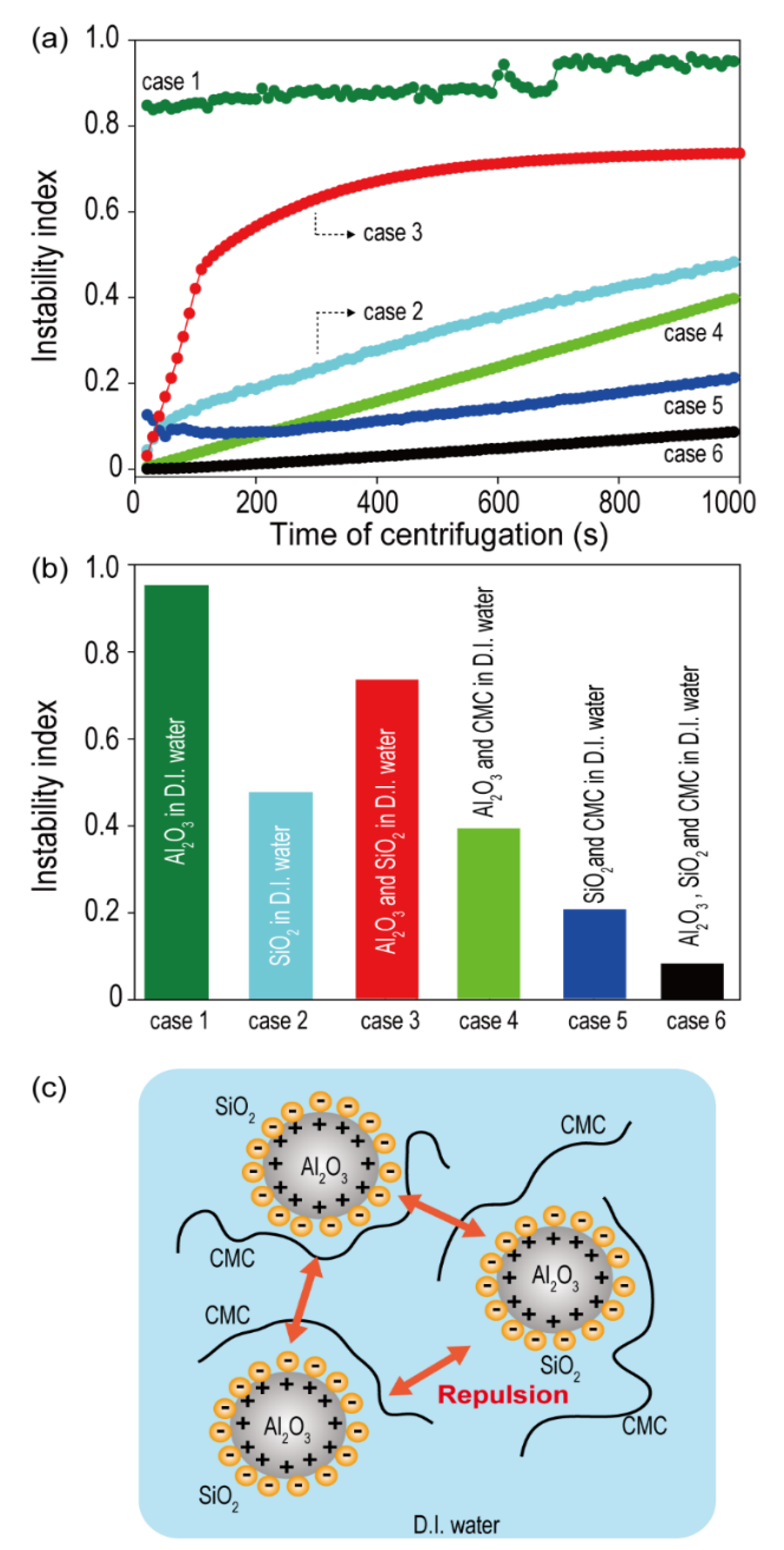
Figure 1a shows the instability index as a function of centrifugation time for all the cases (Case 1 to Case 6) measured using Lumisizer. The instability index, a stability quantifier determined as the ratio of clarification at a given separation time to the maximum clarification in a dispersed system, is a unitless parameter that ranges between 0 and 1. Because lower instability index values indicate a higher system stability, an index of ‘0′ indicates a very stable dispersed system, and an index of ‘1′ indicates complete phase separation [
27,
28,
29]. The instability indices of the samples were determined with a centrifugation time of 1000 s. As shown in
Figure 1b, the order of the instability index was: Case 1 > Case 3 > Case 2 > Case 4 > Case 5 > Case 6. The ceramic solutions containing polymeric binders (Cases 4, 5, and 6) exhibited higher dispersion stabilities compared to those in other cases. This might be attributed to the thickening and gelling effect of CMC, because most polysaccharides behave as emulsion stabilizers by forming an extended network in the continuous phase and thus become highly viscous [
30].
More importantly, the mixture of Al
2O
3 and SiO
2 (Case 6) exhibited a higher improvement in dispersion stability compared to either Al
2O
3 (Case 4) or SiO
2 (Case 5) ceramic alone. The smaller-sized SiO
2 wraps around the surface of the large-sized Al
2O
3 (
Figure 1c), owing to the difference in the particle sizes of Al
2O
3 and SiO
2 along with the opposite polarities of the zeta potentials. The SiO
2 sheath reduces the van der Waals forces between the ceramic particles and also generates an electrostatic repulsive force between the Al
2O
3 particles encased in SiO
2, improving the dispersion stability of the slurry.
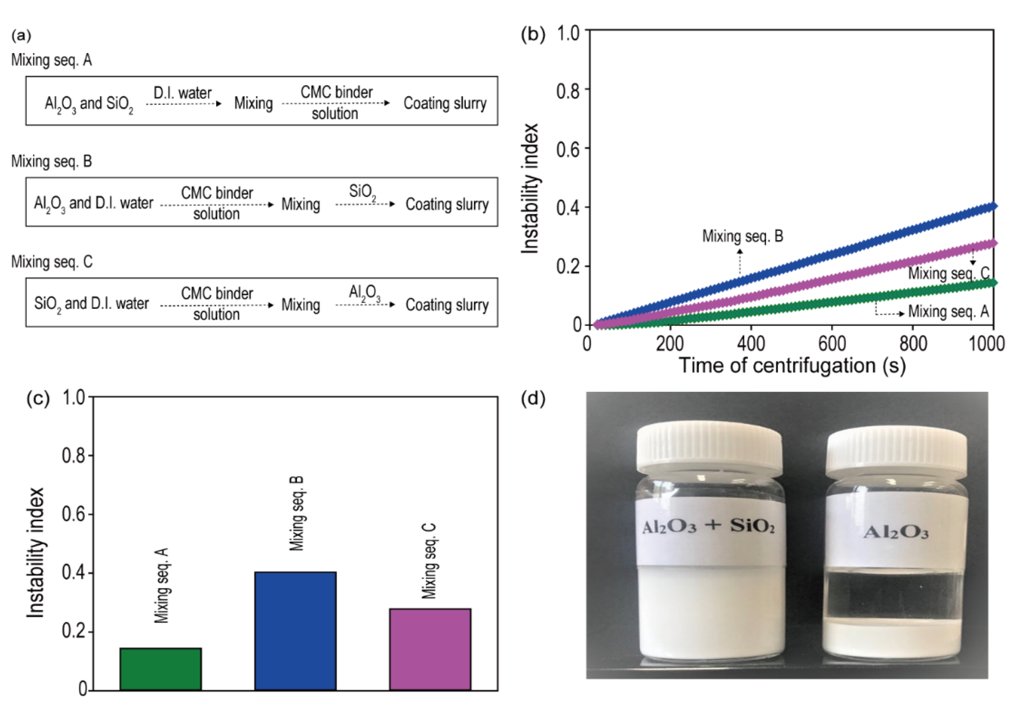
The influence of the order of mixing the ceramic coating slurry components was investigated to optimize the properties of the ceramic coating slurry containing Al
2O
3 and SiO
2. Three ceramic coating slurries were prepared according to the mixing sequences shown in
Figure 2a, and their instability indices were measured. As shown in
Figure 2b,c, the order of the instability index was: mixing sequence B > mixing sequence C > mixing sequence A. This implies that the best dispersion stability of the ceramic coating slurry was achieved when the two ceramics (Al
2O
3 and SiO
2) were premixed prior to the introduction of the CMC polymeric binders. The result seems reasonable because CMC polymeric binders exhibit a negative zeta potential similar to that of SiO
2 (
Table 1). When the CMC polymeric binders encounter Al
2O
3 with a positive zeta potential, they compete with SiO
2 on the Al
2O
3 surface, reducing the likelihood of SiO
2 sheath formation. Considering these results, we selected mixing sequence A for the preparation of a ceramic coating slurry containing Al
2O
3 and SiO
2 to fabricate CCSs. The prepared dual ceramic slurry retained an excellent dispersion stability even after storage for 30 d under gravity at 25 °C (
Figure 2d).
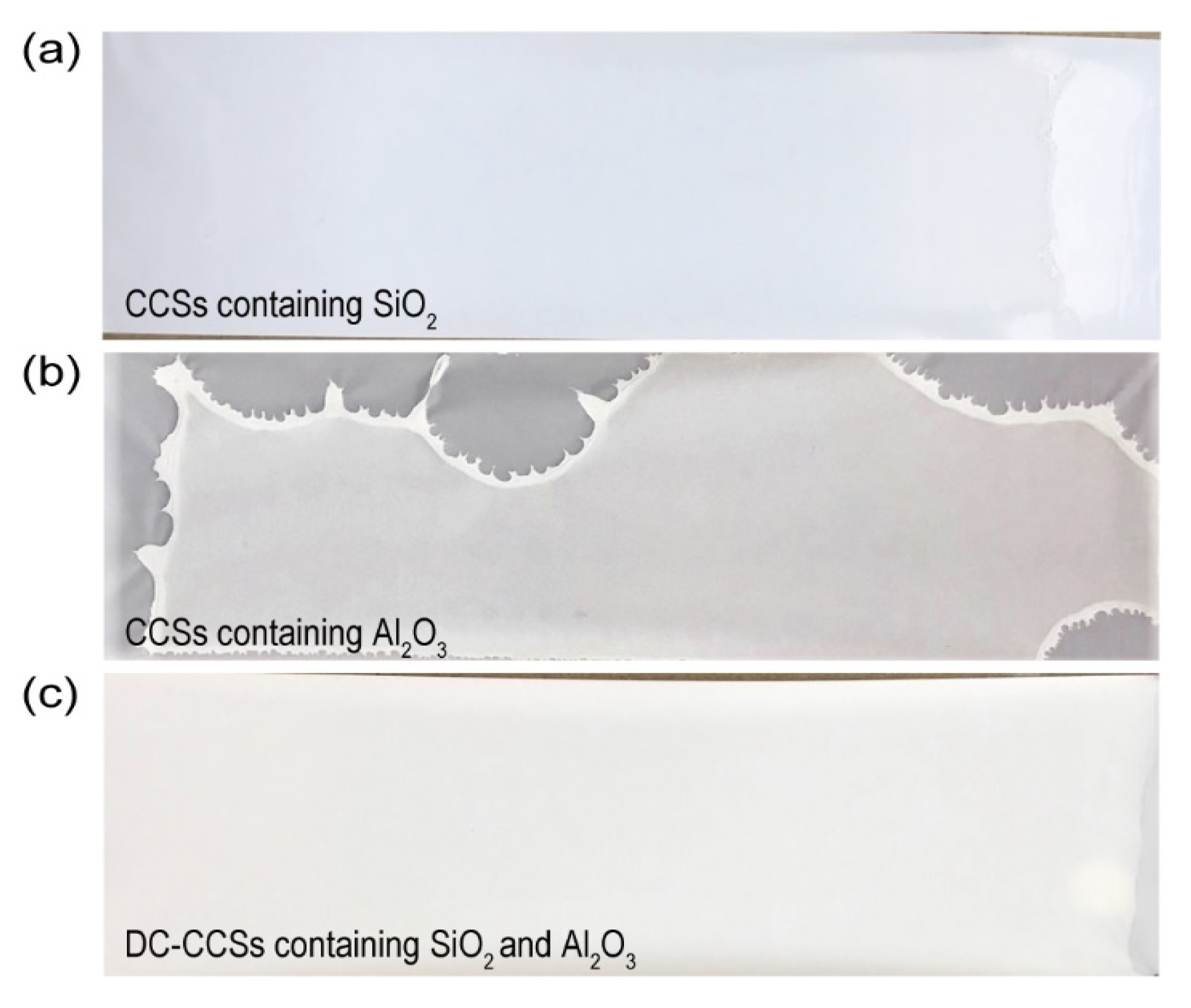
To fabricate DC-CCSs, an aqueous ceramic coating slurry containing dual ceramics (SiO
2 and Al
2O
3) was prepared according to mixing sequence A (corresponding to
Figure 2a) and coated on PE separators using a doctor blade. For comparison, aqueous ceramic coating slurries containing single ceramics, such as SiO
2 and Al
2O
3, were also prepared and coated on PE separators using a doctor blade. The aqueous ceramic coating slurry containing only Al
2O
3 exhibited non-uniform coating, while others exhibited uniform coating on the PE separators (
Figure 3). The non-uniform coating of the ceramic coating slurry containing Al
2O
3 can be attributed to its poor affinity for the hydrophobic PE surface [
13,
31] The cohesive forces between the highly polar water molecules result in the formation of liquid droplets with a low surface tension [
13], and Al
2O
3 particles tend to aggregate in aqueous mixtures, resulting in the weak adhesion of the slurry with the PE separators. Contrastingly, the hydrophilic SiO
2 nanoparticles form a pseudo aerogel matrix that is highly hydrophilic and has a low bulk density, a low thermal conductivity, and a large surface area [
32,
33,
34], resulting in uniform coating on the PE separators. As shown in the FT-IR results, SiO
2 showed more of an abundant peak of hydroxyl groups (–OH) than Al
2O
3 (
Figure S7 in Supplementary Materials). These properties of SiO
2 result in the stability of the coating with the aqueous ceramic coating slurry containing dual ceramics (SiO
2 and Al
2O
3).
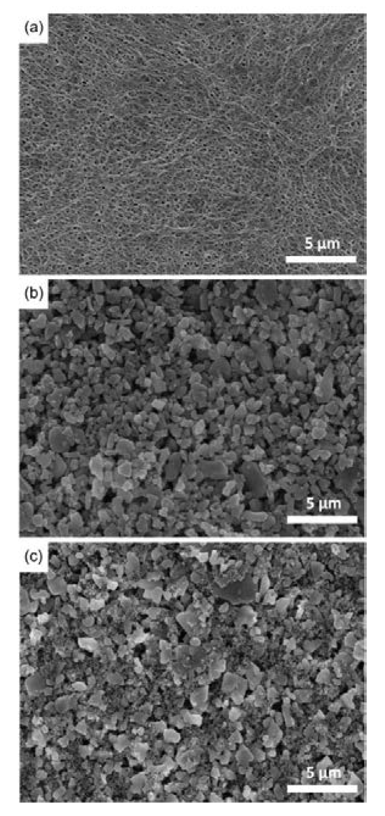
The surface morphology of DC-CCSs was observed using SEM (
Figure 4). For comparison, SEM images were also obtained for the bare PE and SC-CCSs containing Al
2O
3 (which are denoted as SC-CCSs for convenience). In the case of SC-CCSs, the images were carefully obtained from the uniformly coated region shown in
Figure 3b. The bare PE exhibited a microporous structure (
Figure 4a). Although the surface of the bare PE was covered with a ceramic composite for both SC-CCSs and DC-CCSs, the SC-CCSs exhibited a sparsely packed structure (
Figure 4b), and the DC-CCSs exhibited a closely packed structure in which Al
2O
3 gaps were densely filled with small-sized SiO
2 (
Figure 4c), as can be inferred by the grain sizes of Al
2O
3 and SiO
2 (
Figure S5 in Supplementary Materials).
The physical properties of the bare PE, SC-CCSs, and DC-CCSs are listed in
Table 2. Both CCSs exhibited a higher Gurley number compared to that of bare PE owing to a physical barrier of ceramics which reduces the air permeability (bare PE = 288.6 s 100 mL
−1, SC-CCS = 318.4 s 100 mL
−1, DC-CCS = 311.4 s 100 mL
−1). Remarkably, the Gurley number exhibited by the DC-CCSs was lower compared to that exhibited by the SC-CCSs. This might be attributed to the difference in the particle distribution of DC-CCSs, which has a lower bulk density (2.261 g cm
−3) compared to that of SC-CCSs (2.353 g cm
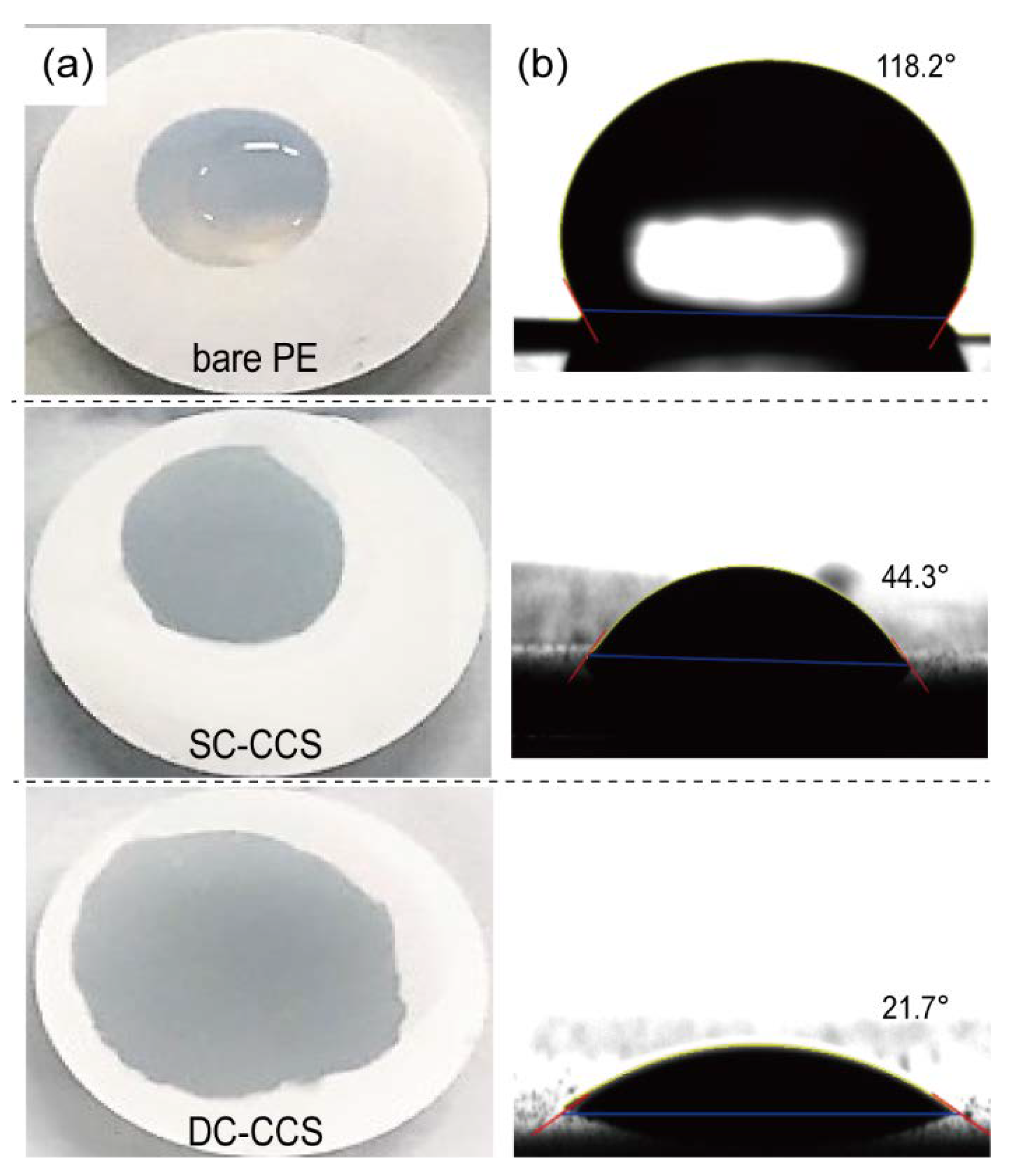
−3). The DC-CCSs exhibited an improved wettability to liquid electrolytes compared to that of the bare PE and SC-CCSs (
Figure 5), owing to the hydrophilic properties of SiO
2 and the morphology of the ceramic composites layer, which increased the electrolyte retention capacity and ionic conductivity (
Table 2 and
Figure S6 in Supplementary Materials). Furthermore, the Li transference number (
t+) showed a similar tendency to the ionic conductivity, which is in good agreement with the previous study (
Table S1 in Supplementary Materials) [
35].
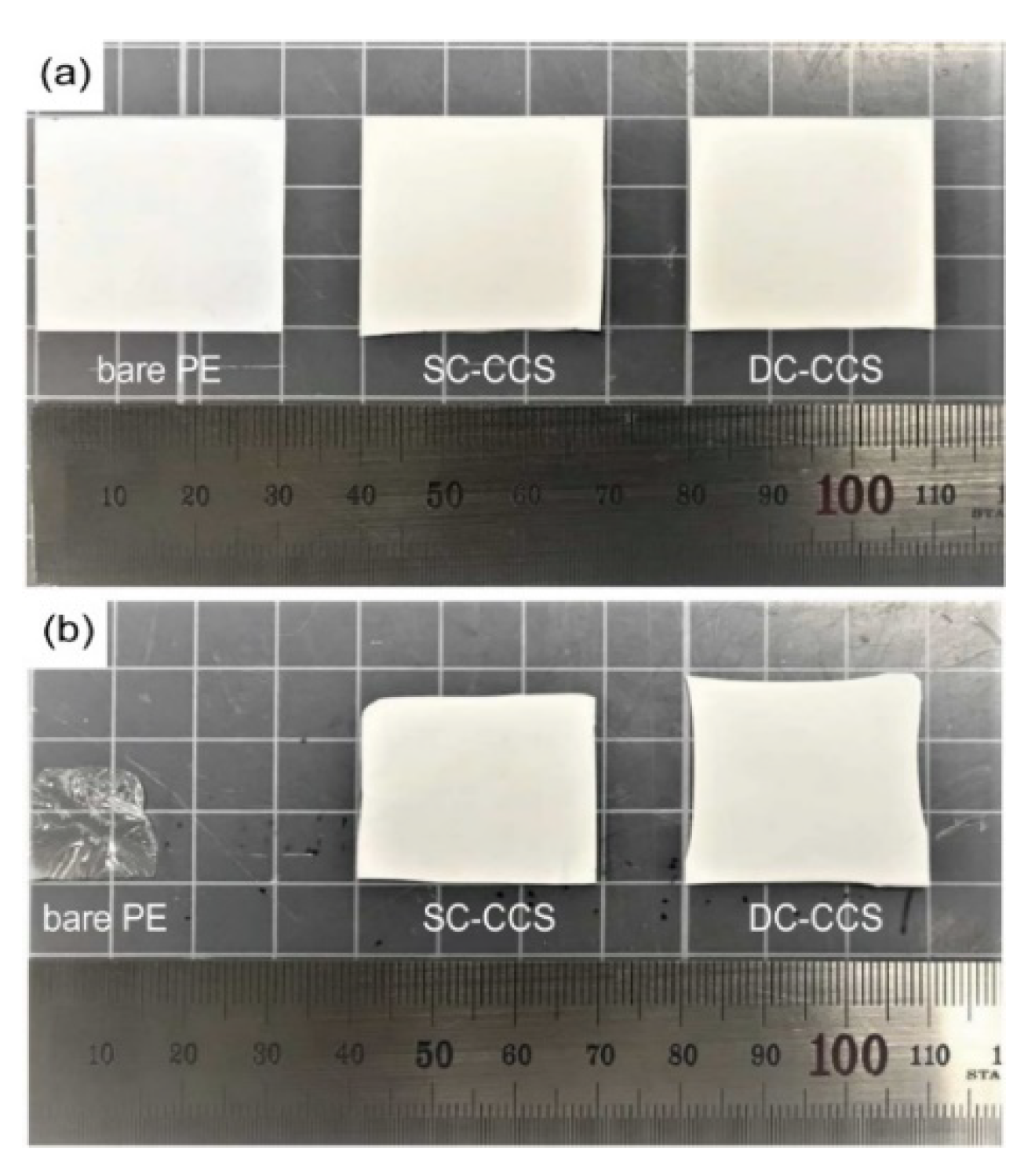
Microporous PE separators easily shrink when exposed to high temperatures owing to the mechanical stress formed on account of stretching during production [
7]. After the separators were exposed to a high temperature of 140 °C for 30 min (
Figure 6), the DC-CCSs exhibited the highest dimensional stability (95.3% of the initial dimension) compared to those exhibited by the bare PE (28.5% of the initial dimension) and SC-CCSs (90.5% of the initial dimension). This implies that the closely packed uniform structure of the ceramic coating layers of the DC-CCSs, verified using SEM (corresponding to
Figure 4), resulted in an enhanced thermal stability compared to those of the bare PE and SC-CCSs.
To investigate the effect of CCSs on the electrochemical performance of Li secondary batteries, the CR2032-type half cells (LMO/Li metal) and full cells (LMO/graphite) were fabricated using base PE, SC-CCSs, and DC-CCSs, respectively, and their rate capability and cycle performance were evaluated.
During the precycling process, the half cells and full cells comprising bare PE, SC-CCSs, and DC-CCSs exhibited similar charge/discharge voltage profiles (
Figure S1 in Supplementary Materials). Contrastingly, the cells consisting of DC-CCSs exhibited an enhanced rate capability and cycle performance compared to those containing bare PE and SC-CCSs (
Figure 7).
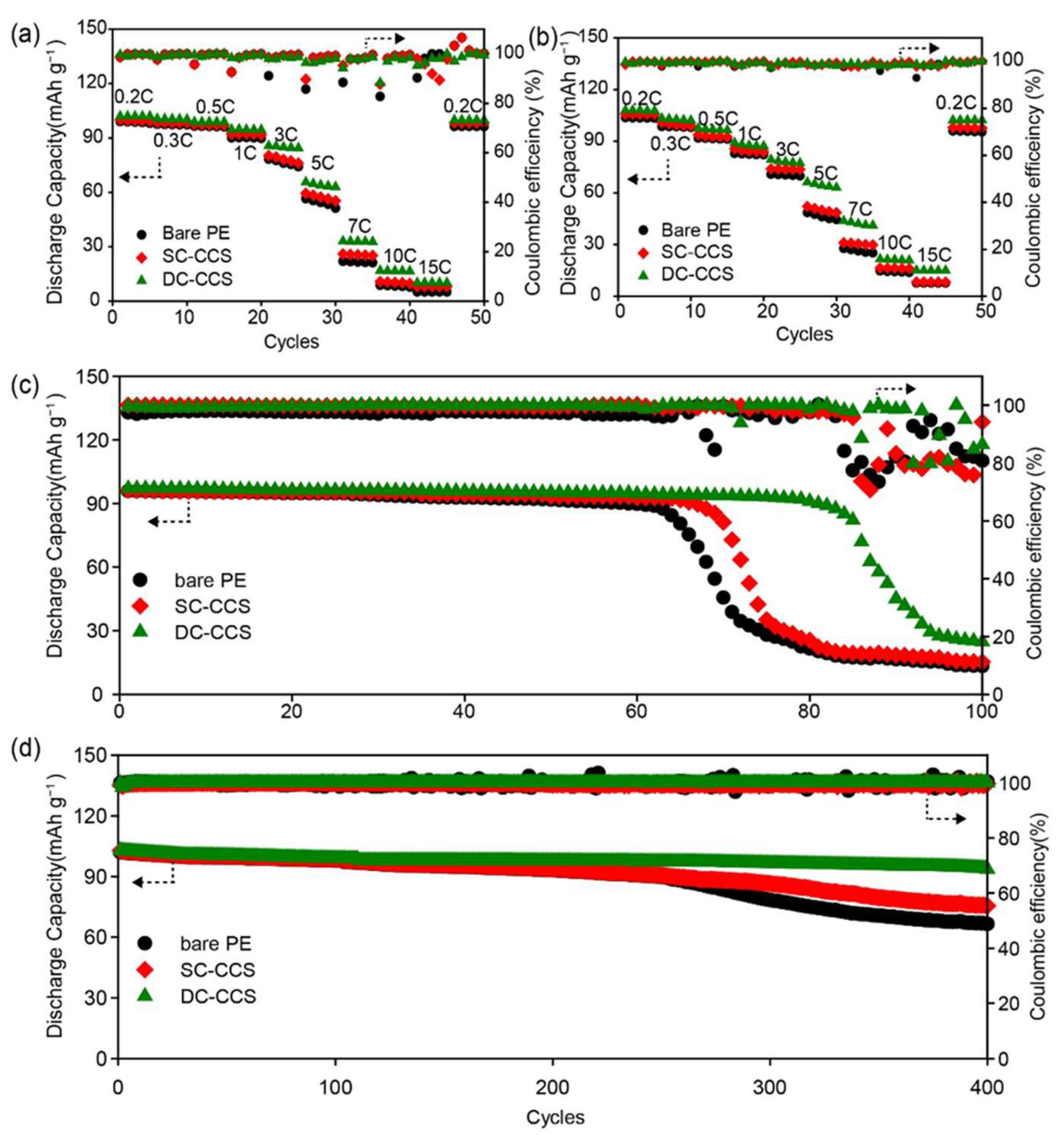
For the rate capability test, the discharging rate was varied between C/5 and 15 C, while the charging current was maintained at the 1 C rate (
Figure 7a,b). After reaching the 15 C rate, the discharging current was restored to C/5 in cycle number 45. Regardless of the type of separator, the discharge capacities of the half cells and full cells were restored to the value obtained in the first cycle. This implies that the reduction in discharge capacity is dominated by kinetic factors and not by the electrochemical consumption of active materials and electrolytes [
13]. The improved rate capabilities of the half cells and full cells containing DC-CCSs are reasonable because DC-CCSs exhibited the highest ionic conductivity and wettability between the three materials tested, as summarized in
Table 2. Furthermore, half cells and full cells containing DC-CCSs exhibited the lowest value of internal resistance compared to other cases where bare PE and SC-CCSs were used (
Figure S2 in Supplementary Materials).
Along with the improved rate capability, the half cells and full cells containing DC-CCSs exhibited an improved cycle performance compared to that of the bare PE and SC-CCSs (
Figure 7c,d). The half cells consisting of DC-CCSs retained 93.8% (97.12 mAh g
−1) of the initial discharge capacity after 80 cycles, while the bare PE and SC-CCSs exhibited 22.5% (21.55 mAh g
−1) and 26.6% (25.55 mAh g
−1) capacity retention, respectively. The full cells comprising DC-CCSs retained 90.9% (102.9 mAh g
−1) of the initial discharge capacity after 400 cycles, while the bare PE and SC-CCS exhibited 64.7% (66.49 mAh g
−1) and 73.4% (75.45 mAh g
−1) capacity retention, respectively.
The dramatic cell capacity fade can be attributed to the formation of a high-resistance surface layer, such as the dendrites, dead Li, and solid electrolyte interphase (SEI) layer, on the anodes that consumes electrolyte and Li ions [
36]. The DC-CCSs have a higher ionic conductivity and uniform ionic flux compared to those of the bare PE and SC-CCSs, owing to their uniform ceramic coating layer and increased wettability to liquid electrolytes, which help in improving the cycle performance of the half cells and full cells [
37]. After the cycling of the half cells, the cells were disassembled, and the surface of the Li metal was observed using SEM (
Figure S3 in Supplementary Materials). As discussed above, the Li metal disassembled from the half cells that contained DC-CCSs exhibited a more uniform morphology compared to that of the bare PE and SC-CCSs.


 ,
, 


