Article

Water-Soluble Conductive Composite Binder for High-Performance Silicon Anode in Lithium-Ion Batteries

1
State Key Laboratory of Organic-Inorganic Composites, College of Chemical Engineering, Beijing University of Chemical Technology, Beijing 100029, China
2
College of Materials Science and Engineering, Beijing University of Chemical Technology, Beijing 100029, China
3
Aerospace Research Institute of Materials & Processing Technology, China Academy of Launch Vehicle Technology, Beijing 100076, China
*
Authors to whom correspondence should be addressed.
Batteries 2022, 8(6), 54; https://doi.org/10.3390/batteries8060054
Submission received: 30 April 2022 / Revised: 27 May 2022 / Accepted: 31 May 2022 / Published: 4 June 2022
(This article belongs to the Special Issue Anodes for High-Performance Li-Ion Batteries)

Abstract

:
The design of novel and high-performance binder systems is an efficient strategy to resolve the issues caused by huge volume changes of high-capacity anodes. Herein, we develop a novel water-soluble bifunctional binder composed of a conductive polythiophene polymer (PED) and high-adhesive polyacrylic acid (PAA) with abundant polar groups. Compared with conventional conductive additives, the flexible conductive polymer can solve the insufficient electrical contact between active materials and the conductive agent, thus providing the integral conductive network, which is extremely important for stable electrochemical performance. Additionally, the polar groups of this composite binder can form double H-bond interactions with the hydroxyl groups of SiO2 layers onto the silicon surface, keeping an integral electrode structure, which can decrease the continuous formation of SEI films during the repeated cycles. Benefiting from these bifunctional advantages, the Si electrodes with the composite binder delivered a high reversible capacity of 2341 mAh g−1 at 1260 mA g−1, good cycle stability with 88.8% retention of the initial reversible capacity over 100 cycles, and high-rate capacity (1150 mAh g−1 at 4200 mA g−1). This work opens up a new venture to develop multifunctional binders to enable the stable operation of high-capacity anodes for high-energy batteries.

1. Introduction

Lithium-ion batteries (LIBs) have been widely applied in various fields, such as portable electronic products, electric vehicles, etc., [1,2,3,4]. With the increasing demand for long-endurance electric vehicles and large-scale grid energy storage, the development of high-energy-density batteries has witnessed increasing attention [5]. The use of high-capacity electrode materials is an efficient strategy to increase the energy density of batteries. As a star high-capacity anode material, the silicon anode possessed a high theoretical capacity of around 4200 mAh g−1, which is ten times more than that of the commercial graphite anode (370 mAh g−1) [6,7,8,9]. However, due to the volume expansion (~400%) and shrinkage of the silicon anode during repeated lithiation and delithiation, the silicon particles suffer from severe pulverization and unstable solid electrolyte interface (SEI), leading to rapid capacity decay and poor cycle stability [10,11,12].
Tremendous efforts have been devoted to handling the above problems, including nano-silicon structure construction [13,14], voltage control [15,16], the development of Si/carbon composites [17,18], the exploration of electrolyte additives [19,20], using high-performance binders [21,22], etc. Among these methods, using high-performance binders can obviously improve the electrochemical performance of Si anodes (especially for nanosized Si) by enhancing the binding force between binder and Si nanoparticles. A series of polymeric binders, including sodium alginate (SA) [23], sodium carboxymethyl cellulose (CMCNa) [24], polyacrylic acid (PAA) [25], polyvinyl alcohol (PVA) [26], gum arabic [27], and guar gum [28], have been applied as high-performance binders for Si anodes. These binders exhibited improved electrochemical performance compared to the traditional commercial binder (polyvinylidene fluoride (PVDF)), which cannot stabilize the Si anodes because of its weak Van Der Waals force between Si particles and PVDF. These novel binders with abundant polar groups (e.g., −COOH, −OH) can form hydrogen bonds and/or covalent bonds with the hydroxyl groups on the surface of Si particles, resulting in an obviously improved cycle performance [29]. For example, PAA-based materials as high-performance binders have received increasing attention due to their flexible carbon backbone and abundant −COOH groups, which can be easily modified by other groups (e.g., −NH2) [30,31]. However, the nanosized Si anodes still suffer from easily losing electronic contacts between Si nanoparticles during cycling due to the lack of mechanical binding force between conductive additives and active materials. The conductive additive is able to detach from the Si nanoparticles caused by large-volume expansion and shrinkage, leading to the broken electrical contact (Figure 1a). Fortunately, the conductive polymers can resolve this problem by improving the performance of nanosized Si due to its flexible features, which can provide a robust conductive network to keep electric contacts during repeated cycles. Several conductive polymers, including polyfluorene [32], poly (phenanthrenequinone) (PPQ) [33], and poly(3,4-ethylenedioxythiophene):poly(styrenesulfonate) (PEDOT: PSS) [34,35] were developed to boost the electrochemical performance of Si anodes. PEDOT: PSS was widely used as a conductive polymer in various fields due to its excellent electrical conductivity, thermal stability, and expedited film formation [36,37,38]. However, as a binder for Si anodes, PEDOT:PSS has several technical issues, such as poor intrinsic electrical conductivity (<1 S cm−1) [39], colloidal particles that aggregate and precipitate during long-term cycles, and an insoluble and intractable nature. The PSS part provides external ions to compensate for the positive charge on the PEDOT with weight 2.5 times that of the PEDOT part [40]. To improve the electrical conductivity of PEDOT: PSS, organic additives are usually added to the polymer systems, such as dimethyl sulfoxide (DMSO), sorbitol, and ethylene glycol (EG) [41]. These disadvantages limit PEDOT: PSS as a high-performance binder for Si anodes. Recently, a self-doped PEDOT was reported, which possessed high and stable electrical conductivity [42], benefiting from this excellent electrical conductivity and stable chemical structure, and may be an ideal conductive binder for high-capacity Si anodes.
Although continuous progress was achieved using these conductive binders, it remains a grand challenge to replace conductive additives using these conductive binders due to the improved electrochemical performance achieved at a low mass loading (<0.3 mg cm−2) [43]. Additionally, an extensive conductive binder (20–30 wt%) was used to prepare the electrode to achieve superior electrochemical performance because of the relatively low mechanical properties of conductive binders with an inherent rigid backbone or rigid anchor points provided by the chemical bond with the Si surface [44]. The low mass loading and high content of the binder in the Si electrode result in a low area and volume capacity, which restricts the energy density of LIBs significantly [29,45]. Thus, the development of efficient conductive binders balancing the adhesion ability and conductivity is key to improving the performance of the Si electrode with high mass loading.
Herein, we developed a bifunctional composite binder, composed of a conductive self-doped polythiophene polymer (poly sodium 4-[(2,3-dihydrothieno [3,4-b] [1,4] dioxin-2-yl) methoxy] butane-2-sulfonate, defined as PED) and polyacrylic acid (PAA), to enable the stable operation of the Si anodes for high-energy batteries. The self-doped polythiophene with high conductivity (34.61 S cm−1) was applied to replace the traditional conductive additive (carbon black, CB) to prepare the Si electrode using a composite binder of PAA and PED (hereinafter referred to as PAA-PED). PAA was added to offer abundant polar groups and improve the swelling performance. The PAA-PED binder could adequately wrap Si nanoparticles (Si NPs) together with the help of double hydrogen-bond interactions initiated by polar groups [43,46], leading to a significantly enhanced adhesion force between the electrode materials. More importantly, the flexible conductive polymer could provide a robust conductive network to maintain electron contact during a long-term charge and discharge process (Figure 1b). Benefiting from these advantages, the Si electrode with the bifunctional PAA-PED achieved a high specific capacity of 4184 mAh g−1 with an initial coulombic efficiency (82.4%), long-term cycle stability, and high-rate capability. This work offers a novel dual-binder strategy for improving the electrochemical performance of silicon anodes in LIBs, which may provide a considerable reference for a higher-mass-loading silicon anode with decent electronic stability.

2. Material and Methods

2.1. Synthesis of the Conductive Polymer

2.1.1. Synthesis of Sodium 4-[(2,3-dihydrothieno [3,4-b] [1,4] dioxin-2-yl) methoxy] butane-2-sulfonate (SED Monomer)

The SED monomer was synthesized from the reaction of hydroxymethyl 3, 4-ethylene dioxythiophene (HMEDOT) and 2,4-butane sultone. Typically, the HMEDOT (0.625 g, 3.63 mmol, Bide Pharmatech, Shanghai, China) was dissolved in 2.4 mL of THF, and then 60 wt% NaH (0.177 g) in THF (1.1 mL) was slowly dropped into the HMEDOT solution. After refluxing for 1 h, 2,4-butane sultone (0.544 g, 3.99 mmol, Aladdin, Shanghai, China) in THF (2.9 mL) was added dropwise into the solution and aged for 2 h to sulfonate HMEDOT. After quenching the reaction with ethanol, the mixture solution was distilled under reduced pressure to remove THF, and then acetone (15.2 mL) was added, obtaining a light-yellow solid. Finally, the obtained solid was recrystallized in toluene, producing the SED monomer with a yield of 64%.

2.1.2. Synthesis of PED

The PED was prepared by oxidative polymerization of the SED monomer. Briefly, the SED monomer (0.3 g, 0.906 mmol) and FeSO4·7H2O (0.15 g, 0.539 mmol; Sinopharm Chemical, Beijing, China) were dissolved in 1 M aqueous sulfuric acid. At the same time, (NH4)2S2O8 (0.414 g, 1.81 mmol; J&K Scientific, Beijing, China) was dissolved in deionized water (41.2 wt%) and slowly added dropwise to the SED solution. The oxidative polymerization was carried out with strong stirring at 20 °C for 20 h under an Ar atmosphere. After polymerization, the obtained product was dissolved in deionized water and dialyzed for two weeks to remove impurity ions as well as small molecules, and then freeze-dried, obtaining a black flocculent solid.

2.2. Material Characterization

Fourier transform infrared spectroscopy (FT-IR, Thermo Fisher Scientific, Waltham, MA, USA) was conducted on an infrared spectrometer using the KBr tablet method (Nicolet IS5). Nuclear magnetic resonance (NMR) spectra (1H and 13C NMR) were recorded in C2D6SO on a Bruker AVANCE III (Bruker Corporation, Billerica, MA, USA) 400 MHz spectrometer. X-ray diffraction (XRD) patterns of the samples were measured on a Bruker D8 ADVANCE instrument (Bruker Corporation, Billerica, MA, USA). Thermogravimetric analysis (TGA) was performed using a Mettler TGA/DSC 3+ thermogravimetric analyzer (Mettler Toledo, Greifensee, Switzerland) with a scanning speed of 10 °C min−1 in a nitrogen atmosphere. Electronic conductivity was measured on a ResMap Four-Point Probe (Jingge Electronic ST2258C, Jingge Electronic Corporation, Suzhou, China). Scanning electron microscopy (SEM, FEI Company, Hillsboro, America) and Transmission electron microscopy (TEM, FEI Company, Hillsboro, OR, USA) images were obtained using SEM (FEI Quanta 250FEG, FEI Company, Hillsboro, OR, USA) and TEM (FEI Tecnai G2 20, FEI Company, Hillsboro, OR, USA), respectively.

2.3. Swelling Ability Test of Binders

The swelling ability of the binders in the liquid electrolyte was conducted to evaluate the compatibility of binders with the electrolyte. The swelling ratio of the binder was calculated as the increased weight of the absorbed electrolyte divided by the initial weight of the binder. The samples were prepared by pressing solid powder into circular films with a diameter of 13 mm and a thickness of 1 mm. The adsorbed experiment was performed by soaking the binder films into the electrolyte at room temperature for 48 h. The weight of the adsorbed electrolyte by the binder was measured immediately after the sample was blotted dry.

2.4. Electrode Preparation

All electrodes were prepared via the casting method using various binders. The prepared procedures (taking the PAA-PED-Si electrode as an example) are illustrated below. Firstly, the homogeneous slurry was obtained by dispersing the Si particles into an aqueous solution containing PAA and PED under stirring for 45 min. Then, the electrode was prepared by casting the slurry on the Cu foil, and dried in a vacuum at 120 °C for 18 h before being punched into 12 mm discs. The areal mass loading of Si on the electrode was within the range of 0.5~0.7 mg cm−2. The PAA-PED-Si electrode was composed of 80 wt% Si NPs, 10 wt% PAA, and 10 wt% PED. For comparison, the control electrodes were prepared using the same method, using CB as a conductive additive. The PAA-CB-Si electrode was composed of 80 wt% Si NPs, 10 wt% PAA, and 10 wt% CB, while the PVDF-CB-Si electrode was composed of 80 wt% Si NPs, 10 wt% PVDF, and 10 wt% CB. In addition, the two-component PED-Si electrode was also prepared by simply mixing Si NPs with the PED aqueous solution with a mass ratio of 8/2.

2.5. Adhesion Performance of the Binders

The adhesion ability of the binder was evaluated by the 180° peeling test, which was carried out on a highly precise mechanical testing system (CMT 4202, Shenzhen Chuyinghao Tech, Shenzhen, China). Typically, an electrode (10 mm × 50 mm) was attached to the sample holder. Then, 3M tape (Scotch 600) was firmly attached to the electrode surface. The applied load was recorded when the tape was pulled to the bottom of the sample holder with a speed of 100 μm s−1 at a direction of 180° angle, and then the force–displacement curve was obtained.

2.6. Electrochemical Measurements

The 2032 coin half cells were assembled for the constant current cyclic electrochemical test. The cells were assembled using 99.9% lithium foil (China Energy Lithium Co., Ltd., Tianjin, China) as the counter electrode, the as-prepared Si electrode as the anode, and polypropylene microporous film (Celgard 2325) as the separator, respectively. The used electrolytes consisted of 1.0 M lithium hexafluorophosphate (LiPF6) in ethylene carbonate (EC) and diethylene carbonate (DEC) (1:1 w/w) with 0.5 wt% of vinylene carbonate (VC) and 7.5 wt% fluoroethylene carbonate (FEC). Galvanostatic charge/discharge measurement was carried out over a voltage range of 0.01~1.5 V at room temperature on a battery testing system (LAND, Wuhan, China). Before testing, the electrode was activated at 0.1 C (1 C = 4200 mAh g−1) in the first cycle, followed by cycle testing at 0.1, 0.2, or 0.3 C, respectively. The specific capacity was calculated based on the weight of the active materials. Cyclic voltammetry (CV) curves were tested using an electrochemical workstation (CHI 760E) at a scanning speed of 0.2 mV s−1 in the voltage range of 0.01~3 V (vs. Li/Li+). Electrochemical impedance spectroscopy (EIS) spectra were conducted using an electrochemical workstation (CHI 760E), with a frequency range of 0.01 Hz to 1 MHz.

3. Results and Discussion

Figure 1c schematically shows the synthetic route to the self-doped conductive polymer (PED), which was prepared by oxidative polymerization of the SED monomer. The SED was synthesized by the reaction of HMEDOT and 2,4-butane sultone. The chemical structure of the SED monomer was confirmed by 1H NMR and 13C NMR spectra (Figure S1), in line with the previously reported results [42]. Additionally, FT-IR spectra of HMEDOT, SED, and PED (Figure S2) were measured to illustrate the chemical change during the synthetic process. Compared with the HMEDOT, the FT-IR spectrum of the SED shows the disappearance of the peak for the stretching vibration of the O-H bond in the −OH group (3228 cm−1) and the appearance of the peak for the stretching vibration of the O-H bond in the −SO3H group (3438 cm−1), exhibiting the transformation from the -OH group to −SO3H group. The vibration peak of the C-S bond in C-SO3H is also observed at 537 cm−1, which further proves the successful synthesis of SED. The FT-IR spectrum of the PED indicates that the asymmetric stretching vibration peak of Cα=Cβ at 1490 cm−1 is weakened to a great extent compared to the SED (Figure S2), indicating that the polymerization of SED was successfully performed because the polymerization took place on the α site of the thiophene ring [42,47,48]. Moreover, XRD patterns in Figure S3 exhibit the diffraction peaks at 5.3°, 10.5°, and 24.7° attributable to the (100), (200), and (020) planes of the orthorhombic unit cell of the PED crystal [49,50,51,52], confirming the successful synthesis of PED. In contrast to non-conductive polymeric binders, such as polyvinylidene fluoride (PVDF) and PAA, the self-doped PED polymer exhibits considerable conductivity (34.61 S cm−1) measured by the four-point technique due to the large π-conjugated organic backbones, as shown in Table S1. TGA results in Figure S4 show that PED polymer would start to decompose at approximately 240 °C, indicating that PED can remain thermally stable as a binder in LIBs.
The electrolyte affinity has an important effect on both structural and electrochemical behaviors of the electrodes, as characterized by the swelling ratio of binders in the electrolyte. A small swelling ratio of the binder may impede the Li+ transmission. On the other hand, a binder with an overly large swelling ratio exhibits poor mechanical strength when adsorbing the electrolyte. As shown in Figure 2a, the PAA-PED binder with an optimum mass ratio of 1:1 exhibits a balanced swelling ratio (~13.88%). The optimal ratio was determined through the 180° peeling test and the 20-round charge and discharge test. As illustrated in Figure S5, the Si electrode, with mass ratios of Si NPs, PAA, and PED (8: 1: 1), showed the highest binding force and the most stable cycle life. Moreover, the Si NPs used for the preparation of Si electrodes were characterized by XRD, SEM, and TEM measurements. The Si NPs possess a crystalline structure with high purity (Figure S6) and a spherical structure with diameters in the range of 50~200 nm (Figure S7). Moreover, the existence of Si oxide with a thickness of ~ 3 nm on the surface of Si NPs is confirmed by TEM analysis (Figure S8).
The adhesion ability of a binder is of vital importance to the electrochemical performance of electrodes. Binders with poor binding ability often fail to restrain the separation between Si NPs and conductive additives, as well as delamination from the current collector, which subsequently leads to fast capacity fading and current interruption during repeated charge/discharge cycles. Thus, it is ideal for binders to provide a strong binding force for the Si anode. Si electrodes using different binders, with a mass ratio of 8:1:1, were prepared, and their adhesion abilities were examined by the 180° peeling test. Figure 2b shows that the PAA-PED-Si electrode exhibits the best bonding performance with an average adhesion force of 1.63 N, which is significantly higher than that of the PAA-CB-Si electrode (0.88 N) and PVDF-CB-Si electrode (0.14 N). In addition, the PAA-PED-Si electrode shows little shedding of electrode materials after peeling, in contrast to the other two electrodes (Figure 2c), indicating that a considerable improvement in binding ability is achieved by the co-use of PAA and PED. To gain insight into the enhanced effect, FT-IR spectra were explored to test the interaction of the Si electrode with different binders. FT-IR spectra in Figure 2d illustrate that the stretching vibration peak of the −SO3H group for PED at ~1049 cm−1 slightly red-shifted to ~1065 cm−1 after the homogeneous mixture of Si NPs and PED, corresponding to the H-bond interaction between PED and Si NPs, while no interference was observed from the FT-IR spectra of Si NPs. Moreover, the H-bond interaction between PAA and Si NPs was widely proved in previous reports [53]. It should be noted that the peak at ~1250 cm−1 in PED was associated with the vibration peak of the C-C bond on the thiophene ring, which may be covered by the strong peak at 1203 cm−1 in the spectrum of PED-Si (Figure 2d). Thus, it is reasonable to conclude that the improved adhesion performance is attributed to dual H-bond interactions amongst the PAA-PED binder and Si NPs, as illustrated in Figure 2e.
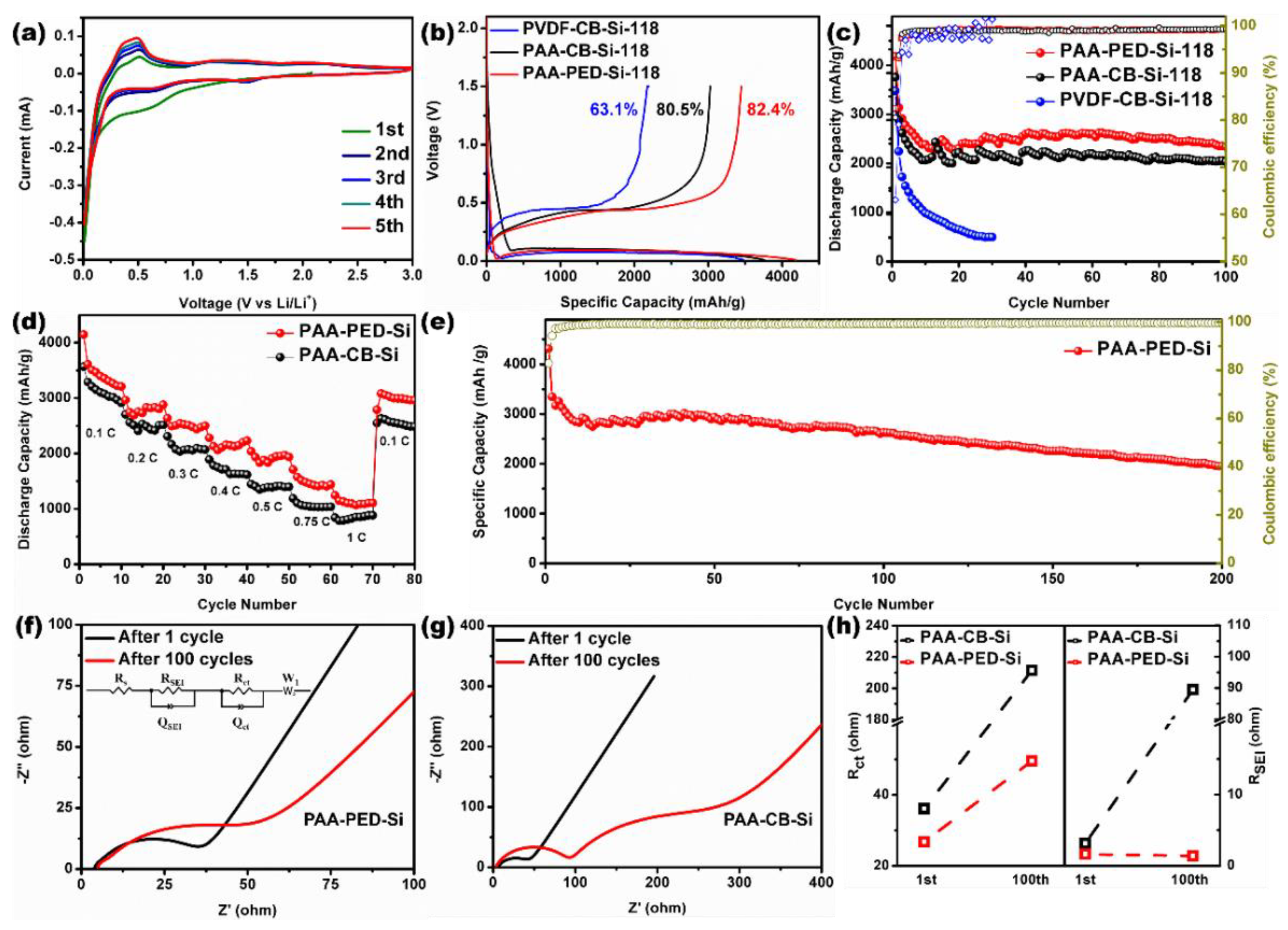
Figure 3a exhibits the first five cyclic voltammetry (CV) curves of a typical PAA-PED-Si electrode at a scanning rate of 0.2 mV s−1. During the first negative sweep, a weak but broad peak appears at 0.9~1.5 V, corresponding to irreversible side reactions within the battery system. The peak at 0.74 V is attributed to the decomposition of the electrolyte and the formation of the SEI layer. Lithiation starts at approximately 0.31 V and dropped rapidly below 0.2 V. Besides, two oxidation peaks at 0.35 and 0.56 V appear as a result of the two-step delithiation during the first positive sweep. The result is consistent with previous reports [54]. The excellent repeatability of the subsequent curves demonstrates a highly reversible lithiation/delithiation behavior of the PAA-PED-Si electrode, and the charge/discharge current gradually increases with an increasing cycle number owing to the activation of Si NPs embedded deep in the electrode.
Figure 3b exhibits the initial discharge–charge curves of various electrodes, which were performed at a low current density of 0.1 C to ensure an adequate activation of Si NPs. The long plateaus below 0.1 V during the discharge process suggest a continuous alloying reaction between Li and Si to form amorphous LixSiy, resulting in high initial discharge capacity. Among these electrodes, the PAA-PED-Si delivered the highest initial discharge capacity of 4184 mAh g−1 with an initial Coulombic efficiency (CE) of 82.4%, which is obviously higher than those of PAA-CB-Si (3757 mAh g−1, 80.5%) and PVDF-CB-Si (3481 mAh g−1, 63.1%). Figure 3c displays the cycling performance of three electrodes at 0.3 C, illustrating that the PAA-PED-Si also possessed the highest stable capacity and cycling stability. It should be noted that rapid capacity loss at the initial five cycles for all electrodes was observed, which can be ascribed to the side reaction and consumption of reversible Li+ during the formation of SEI. The PAA-PED-Si electrode achieved a considerable reversible capacity of 2637 mAh g−1 at the 6th cycle and maintained 2341 mAh g−1 after 100 cycles with a capacity retention rate of 88.8%. On the contrary, the PAA-CB-Si electrode only achieved a reversible capacity of 2036 mAh g−1 after 100 cycles with a reversible retention rate of 72.5%. The PVDF-CB-Si electrode even stopped working after 31 cycles with little capacity left.
The PAA-PED-Si electrode also shows good rate performance. As shown in Figure 3d, the PAA-PED-Si electrode delivered a high reversible specific capacity of 3306, 2747, 2492, 2131, 1934, 1575, and 1150 mAh g−1 when the current density increases from 0.1 C, 0.2 C, 0.3 C, 0.4 C, 0.5 C, 0.75 C, and 1 C, respectively. The reversible capacity of the PAA-PED-Si electrode recovered to 3057 mAh g−1 when the current density changed from 1 C to 0.1 C after various cycles. All specific capacities of the PAA-PED-Si electrode at various current densities are higher than that of PAA-CB-Si, illustrating the superior rate capability of the PAA-PED-Si electrode. To further evaluate the cycling stability of the PAA-PED-Si electrode, a long-term cycling test was carried out at 0.2 C. The PAA-PED-Si electrode shows long-term stability with a high capacity of approximately 2000 mAh g−1 after 200 cycles (Figure 3e).
To certify the advantage of the PAA-PED binder for keeping good conductivity during cycling, EIS measurements were also conducted on the PAA-PED-Si and PAA-CB-Si electrodes after the 1st and 100th cycles. As shown in Figure 3f,g, all fitted EIS curves exhibit two semicircles, which correspond to the impedance of SEI (RSEI) and charge transfer (RCT) in terms of the equivalent circuit model, respectively. The PAA-PED-Si electrode shows a slight change in RSEI (from 1.61 to 1.37 Ω), and RCT (from 26.74 Ω to 49.53 Ω) after 100 cycles. In contrast, both RSEI and RCT of the PAA-CB-Si electrode show an enormous increase after 100 cycles (Figure 3h). Thus, it can be concluded that an excellent conductive network was structured and maintained by PAA-PED, leading to an improved cycling performance of the electrode.
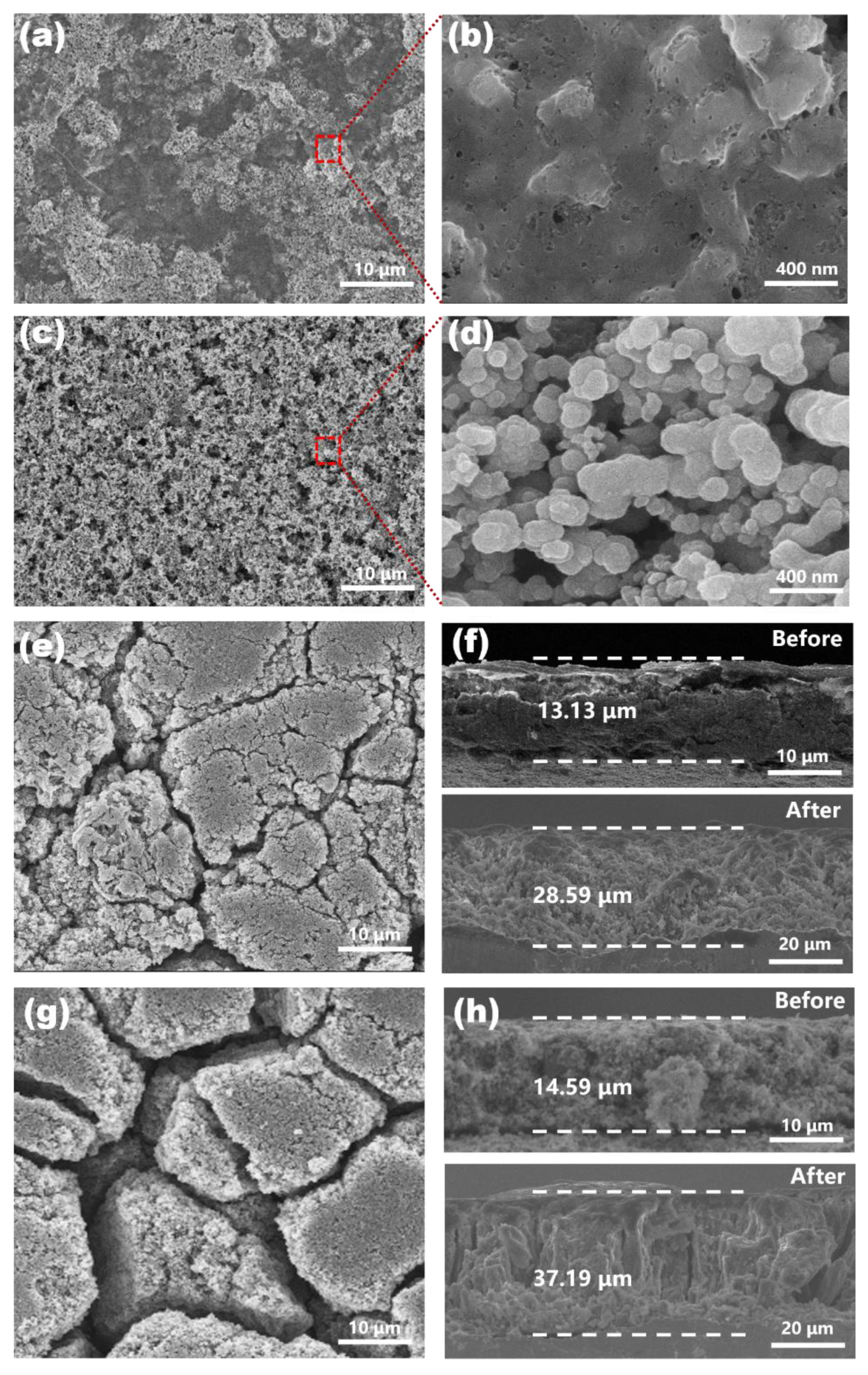
To investigate the structural changes of the electrodes, the morphologies of different electrodes before and after cycling were investigated by SEM spectrology. Before cycling, it can be clearly seen from the top-view SEM images that the silicon NPs are regionally wrapped together on the electrode surface of PAA-PED-Si (Figure 4a,b), while the particles stay individually separated on the PAA-CB-Si electrode (Figure 4c,d). After 100 cycles at 0.3 C, the PAA-PED-Si electrode (Figure 4e) displays a more complete structure with a few shallow and narrow cracks. However, the PAA-CB-Si electrode (Figure 4g) shows deep and broad cracks, and the overall structure was mostly broken. The results illustrate that the PAA-PED-Si electrode, with its much better structural stability, has the ability to maintain good electron transportation for subsequent cycling. Meanwhile, the contact between the active material and the conductive additive was severely devastated on the PAA-CB-Si electrode, which seriously restricts its long-term cycle stability.
The cross-sectional views of the electrodes directly reveal the thickness change caused by volume changes during cycling. During repeated lithiation and delithiation, all of the silicon electrodes expanded significantly (Figure 4f,h). After 100 cycles, the thickness of the PAA-PED-Si electrode increased to 28.59 μm from the original state of 13.13 μm (117.7% increase), which is lower than that of the thickness increase in the PAA-CB-Si electrode (154.9%) from 14.59 to 37.19 μm. The results indicate that the strong adhesion force generated by multiple interactions between the PAA-PED binder and Si NPs can effectively impede the expansion of silicon and maintain the structural integrity of the electrode. The excellent adhesive ability combined with the robust conductive network provided by the PAA-PED binder enabled an integral electrode structure and stable electric contact between two Si particles, leading to excellent electrochemical performance.

4. Conclusions

In summary, we developed novel water-soluble bifunctional binders composed of a conductive polythiophene polymer and polar polyacrylic acid. The bifunctional binders can not only provide a stable conductive network during long-term cycling but can also maintain an integral electrode structure via the formation of an ester bond between the carboxyl groups of PAA and the hydroxyl groups of the Si surface. These bifunctional advantages endow the Si electrode with superior electrochemical performance. The as-prepared Si electrode with the binders delivered a high capacity of 2341 mAh g−1 at 0.3 C over 100 cycles, long-term stability (88.8% retention), and high-rate capability (1106 mAh g−1 at 1 C). The excellent performance of the Si/PAA-PED electrode is mainly attributed to the composite strategy of PAA and PED. This work provides a promising strategy to develop a water-soluble conductive polymeric binder to resolve the issues caused by large-volume changes of silicon anodes and other high-capacity electrode materials.

Supplementary Materials

The following supporting information can be downloaded at: https://www.mdpi.com/article/10.3390/batteries8060054/s1, Figure S1: (a) The chemical structure of the SED monomer and 1H NMR spectra of SED; (b) 13C NMR spectra of SED; Figure S2: FT-IR spectra of HMEDOT, SED and PED; Figure S3: XRD pattern of PED; Figure S4: TGA and DTG curves of PED; Figure S5: (a) 180°peeling test of electrodes based on different mass ratios of Si NPs, PAA and PED; (b) 20-round charge and discharge test of the electrodes mentioned above at 0.1 C; Figure S6: XRD spectra of Si NPs; Figure S7: SEM image of Si NPs; Figure S8: TEM image of Si NPs; Table S1: Electronic conductivity of PED, PAA and PVDF. The Supplementary Materials is available free of charge.

Author Contributions

Conceptualization, D.L. and A.G.; methodology, Z.L.; software, Z.L.; validation, Z.L.; formal analysis, Z.L.; investigation, Z.L.; resources, D.L.; data curation, Z.L.; writing—original draft preparation, Z.L.; writing—review and editing, D.L. and A.G.; visualization, D.L.; supervision, D.L.; project administration, D.L.; funding acquisition, D.L. All authors have read and agreed to the published version of the manuscript.

Funding

This work was partly funded by the National Natural Science Foundation of China (21905017), the Distinguished Scientist Program at BUCT (buctylkxj02), and the Fundamental Research Funds for Central Universities (buctrc202007).

Institutional Review Board Statement

Not applicable.

Informed Consent Statement

Not applicable.

Data Availability Statement

The data presented in this study are available on request from the corresponding author. The data are not publicly available due to confidentiality.

Conflicts of Interest

The authors declare no conflict of interest.

References

  1. Liu, J.; Bao, Z.; Cui, Y.; Dufek, E.J.; Goodenough, J.B.; Khalifah, P.; Li, Q.; Liaw, B.Y.; Liu, P.; Manthiram, A.; et al. Pathways for practical high-energy long-cycling lithium metal batteries. Nat. Energy 2019, 4, 180–186. [Google Scholar] [CrossRef]
  2. Lu, J.; Chen, Z.; Ma, Z.; Pan, F.; Curtiss, L.A.; Amine, K. The role of nanotechnology in the development of battery materials for electric vehicles. Nat. Nanotechnol. 2016, 11, 1031–1038. [Google Scholar] [CrossRef]
  3. Wei, Y.; Zheng, J.; Cui, S.; Song, X.; Su, Y.; Deng, W.; Wu, Z.; Wang, X.; Wang, W.; Rao, M.; et al. Kinetics tuning of li-ion diffusion in layered Li(NixMnyCoz)O2. J. Am. Chem. Soc. 2015, 137, 8364–8367. [Google Scholar] [CrossRef] [PubMed]
  4. Zheng, J.; Liu, T.; Hu, Z.; Wei, Y.; Song, X.; Ren, Y.; Wang, W.; Rao, M.; Lin, Y.; Chen, Z.; et al. Tuning of thermal stability in layered Li(NixMnyCoz)O2. J. Am. Chem. Soc. 2016, 138, 13326–13334. [Google Scholar] [CrossRef] [PubMed]
  5. Van Noorden, R. The rechargeable revolution: A better battery. Nature 2014, 507, 26–28. [Google Scholar] [CrossRef] [Green Version]
  6. Armand, M.; Tarascon, J.M. Building better batteries. Nature 2008, 451, 652–657. [Google Scholar] [CrossRef] [PubMed]
  7. Dunn, B.; Kamath, H.; Tarascon, J.M. Electrical energy storage for the grid: A battery of choices. Science 2011, 334, 928–935. [Google Scholar] [CrossRef] [Green Version]
  8. Ji, L.; Lin, Z.; Alcoutlabi, M.; Zhang, X. Recent developments in nanostructured anode materials for rechargeable lithium-ion batteries. Energy Environ. Sci. 2011, 4, 2682–2699. [Google Scholar] [CrossRef]
  9. Yang, Z.; Zhang, J.; Kintner-Meyer, M.C.; Lu, X.; Choi, D.; Lemmon, J.P.; Liu, J. Electrochemical energy storage for green grid. Chem. Rev. 2011, 111, 3577–3613. [Google Scholar] [CrossRef]
  10. Kwon, Y.H.; Minnici, K.; Park, J.J.; Lee, S.R.; Zhang, G.; Takeuchi, E.S.; Takeuchi, K.J.; Marschilok, A.C.; Reichmanis, E. SWNT anchored with carboxylated polythiophene “links” on high-capacity li-ion battery anode materials. J. Am. Chem. Soc. 2018, 140, 5666–5669. [Google Scholar] [CrossRef]
  11. Obrovac, M.N.; Chevrier, V.L. Alloy negative electrodes for li-ion batteries. Chem. Rev. 2014, 114, 11444–11502. [Google Scholar] [CrossRef] [PubMed]
  12. Yoshio, M.; Tsumura, T.; Dimov, N. Electrochemical behaviors of silicon based anode material. J. Power Sources 2005, 146, 10–14. [Google Scholar] [CrossRef]
  13. Kim, H.; Seo, M.; Park, M.H.; Cho, J. A critical size of silicon nano-anodes for lithium rechargeable batteries. Angew. Chem. Int. Ed. 2010, 49, 2146–2149. [Google Scholar] [CrossRef] [PubMed]
  14. Zhang, S. Chemomechanical modeling of lithiation-induced failure in high-volume-change electrode materials for lithium ion batteries. NPJ Comput. Mater. 2017, 3, 8986. [Google Scholar] [CrossRef]
  15. Li, J.; Dahn, J.R. An in situ x-ray diffraction study of the reaction of li with crystalline si. J. Electrochem. Soc. 2007, 154, A156. [Google Scholar] [CrossRef]
  16. Mazouzi, D.; Lestriez, B.; Roueé, L.; Guyomard, D. Silicon composite electrode with high capacity and long cycle life. Electrochem. Solid ST. 2009, 12, A215. [Google Scholar] [CrossRef]
  17. Liu, Y.; Zhu, Y.; Cui, Y. Challenges and opportunities towards fast-charging battery materials. Nat. Energy 2019, 4, 540–550. [Google Scholar] [CrossRef]
  18. Zhang, F.; Zhu, G.; Wang, K.; Li, M.; Yang, J. Encapsulation of core-satellite silicon in carbon for rational balance of the void space and capacity. Chem. Commun. 2019, 55, 10531–10534. [Google Scholar] [CrossRef]
  19. Michan, A.L.; Parimalam, B.S.; Leskes, M.; Kerber, R.N.; Yoon, T.; Grey, C.P.; Lucht, B.L. Fluoroethylene carbonate and vinylene carbonate reduction: Understanding lithium-ion battery electrolyte additives and solid electrolyte interphase formation. Chem. Mater. 2016, 28, 8149–8159. [Google Scholar] [CrossRef]
  20. Park, J.M.; Kim, S.; Ha, J.H.; Kim, S.W.; Lee, J.; Park, S.; Cho, B.-W.; Choi, H.-J. Enhancing the stability of silicon nanosheets electrodes by fluoroethylene carbonate. Chem. Phys. Lett. 2017, 684, 383–389. [Google Scholar] [CrossRef]
  21. Choi, S.; Kwon, T.-W.; Coskun, A.; Choi, J.W. Highly elastic binders integrating polyrotaxanes for silicon microparticle anodes in lithium ion batteries. Science 2017, 357, 279–283. [Google Scholar] [CrossRef] [Green Version]
  22. Zou, F.; Manthiram, A. A review of the design of advanced binders for high-performance batteries. Adv. Energy Mater. 2020, 10, 2002508. [Google Scholar] [CrossRef]
  23. Kovalenko, I.; Zdyrko, B.; Magasinski, A.; Hertzberg, B.; Milicev, Z.; Burtovyy, R.; Luzinov, I.; Yushin, G. A major constituent of brown algae for use in high-capacity li-ion batteries. Science 2011, 334, 75–79. [Google Scholar] [CrossRef]
  24. Li, J.; Lewis, R.B.; Dahn, J.R. Sodium carboxymethyl cellulose. Electrochem. Solid ST 2007, 10, A17. [Google Scholar] [CrossRef]
  25. Magasinski, A.; Zdyrko, B.; Kovalenko, I.; Hertzberg, B.; Burtovyy, R.; Huebner, C.F.; Fuller, T.F.; Luzinov, I.; Yushin, G. Toward efficient binders for li-ion battery si-based anodes: Polyacrylic acid. ACS Appl. Mater. Interfaces 2010, 2, 3004–3010. [Google Scholar] [CrossRef] [PubMed]
  26. Preman, A.N.; Lee, H.; Yoo, J.; Kim, I.T.; Saito, T.; Ahn, S.-K. Progress of 3d network binders in silicon anodes for lithium ion batteries. J. Mater. Chem. A 2020, 8, 25548–25570. [Google Scholar] [CrossRef]
  27. Ling, M.; Xu, Y.; Zhao, H.; Gu, X.; Qiu, J.; Li, S.; Wu, M.; Song, X.; Yan, C.; Liu, G.; et al. Dual-functional gum arabic binder for silicon anodes in lithium ion batteries. Nano Energy 2015, 12, 178–185. [Google Scholar] [CrossRef] [Green Version]
  28. Liu, J.; Zhang, Q.; Zhang, T.; Li, J.-T.; Huang, L.; Sun, S.-G. A robust ion-conductive biopolymer as a binder for Si anodes of lithium-ion batteries. Adv. Funct. Mater. 2015, 25, 3599–3605. [Google Scholar] [CrossRef]
  29. Xu, Z.; Yang, J.; Zhang, T.; Nuli, Y.; Wang, J.; Hirano, S.-I. Silicon microparticle anodes with self-healing multiple network binder. Joule 2018, 2, 950–961. [Google Scholar] [CrossRef] [Green Version]
  30. Wan, X.; Mu, T.; Shen, B.; Meng, Q.; Lu, G.; Lou, S.; Zuo, P.; Ma, Y.; Du, C.; Yin, G. Stable silicon anodes realized by multifunctional dynamic cross-linking structure with self-healing chemistry and enhanced ionic conductivity for lithium-ion batteries. Nano Energy 2022, 99, 107334. [Google Scholar] [CrossRef]
  31. Zhang, B.; Liu, D.; Xie, H.; Wang, D.; Hu, C.; Dai, L. In-situ construction of chemically bonded conductive polymeric network for high-performance silicon microparticle anodes in lithium-ion batteries. J. Power Sources 2022, 539, 231591. [Google Scholar] [CrossRef]
  32. Liu, G.; Xun, S.; Vukmirovic, N.; Song, X.; Olalde-Velasco, P.; Zheng, H.; Battaglia, V.S.; Wang, L.; Yang, W. Polymers with tailored electronic structure for high capacity lithium battery electrodes. Adv. Mater. 2011, 23, 4679–4683. [Google Scholar] [CrossRef] [PubMed] [Green Version]
  33. Kim, S.-M.; Kim, M.H.; Choi, S.Y.; Lee, J.G.; Jang, J.; Lee, J.B.; Ryu, J.H.; Hwang, S.S.; Park, J.-H.; Shin, K.; et al. Poly(phenanthrenequinone) as a conductive binder for nano-sized silicon negative electrodes. Energy Environ. Sci. 2015, 8, 1538–1543. [Google Scholar] [CrossRef]
  34. Higgins, T.M.; Park, S.-H.; King, P.J.; Zhang, C.; McEvoy, N.; Berner, N.C.; Daly, D.; Shmeliov, A.; Khan, U.; Duesberg, G. A commercial conducting polymer as both binder and conductive additive for silicon nanoparticle-based lithium-ion battery negative electrodes. ACS Nano 2016, 10, 3702–3713. [Google Scholar] [CrossRef]
  35. Wang, L.; Liu, T.; Peng, X.; Zeng, W.; Jin, Z.; Tian, W.; Gao, B.; Zhou, Y.; Chu, P.K.; Huo, K. Highly stretchable conductive glue for high-performance silicon anodes in advanced lithium-ion batteries. Adv. Funct. Mater. 2018, 28, 1704858. [Google Scholar] [CrossRef]
  36. Jonas, F.; Krafft, W.; Muys, B. Poly(3, 4-ethylenedioxythiophene): Conductive coatings, technical applications and properties. Macromol. Symp. 1995, 100, 169–173. [Google Scholar] [CrossRef]
  37. Hohnholz, D.; Okuzaki, H.; MacDiarmid, A.G. Plastic electronic devices through line patterning of conducting polymers. Adv. Funct. Mater. 2005, 15, 51–56. [Google Scholar] [CrossRef]
  38. Kirchmeyer, S.; Reuter, K. Scientific importance, properties and growing applications of poly(3,4-ethylenedioxythiophene). J. Mater. Chem. 2005, 15, 2077–2088. [Google Scholar] [CrossRef]
  39. Shi, H.; Liu, C.; Jiang, Q.; Xu, J. Effective approaches to improve the electrical conductivity of Pedot:Pss: A review. Adv. Electron. Mater. 2015, 1, 1500017. [Google Scholar] [CrossRef]
  40. Horii, T.; Hikawa, H.; Katsunuma, M.; Okuzaki, H. Synthesis of highly conductive Pedot:Pss and correlation with hierarchical structure. Polymer 2018, 140, 33–38. [Google Scholar] [CrossRef]
  41. Ashizawa, S.; Horikawa, R.; Okuzaki, H. Effects of solvent on carrier transport in poly(3,4-ethylenedioxythiophene)/poly(4-styrenesulfonate). Synth. Met. 2005, 153, 5–8. [Google Scholar] [CrossRef]
  42. Yano, H.; Kudo, K.; Marumo, K.; Okuzaki, H. Fully soluble self-doped poly(3,4-ethylenedioxythiophene) with an electrical conductivity greater than 1000 s cm−1. Sci. Adv. 2019, 5, eaav9492. [Google Scholar] [CrossRef] [PubMed] [Green Version]
  43. Liu, D.; Zhao, Y.; Tan, R.; Tian, L.-L.; Liu, Y.; Chen, H.; Pan, F. Novel conductive binder for high-performance silicon anodes in lithium ion batteries. Nano Energy 2017, 36, 206–212. [Google Scholar] [CrossRef]
  44. Jiao, X.; Yin, J.; Xu, X.; Wang, J.; Liu, Y.; Xiong, S.; Zhang, Q.; Song, J. Highly energy-dissipative, fast self-healing binder for stable si anode in lithium-ion batteries. Adv. Funct. Mater. 2020, 31, 5699. [Google Scholar] [CrossRef]
  45. Zeng, X.; Shi, Y.; Zhang, Y.; Tang, R.; Wei, L. Vinyltriethoxysilane crosslinked poly(acrylic acid sodium) as a polymeric binder for high performance silicon anodes in lithium ion batteries. RSC Adv. 2018, 8, 29230–29236. [Google Scholar] [CrossRef] [Green Version]
  46. Hays, K.A.; Ruther, R.E.; Kukay, A.J.; Cao, P.; Saito, T.; Wood, D.L.; Li, J. What makes lithium substituted polyacrylic acid a better binder than polyacrylic acid for silicon-graphite composite anodes? J. Power Sources 2018, 384, 136–144. [Google Scholar] [CrossRef]
  47. Senthilkumar, B.; Thenamirtham, P.; Kalai Selvan, R. Structural and electrochemical properties of polythiophene. Appl. Surf. Sci. 2011, 257, 9063–9067. [Google Scholar] [CrossRef]
  48. Jang, J.; Chang, M.; Yoon, H. Chemical sensors based on highly conductive poly (3,4-ethylenedioxythiophene) nanorods. Adv. Mater. 2005, 17, 1616–1620. [Google Scholar] [CrossRef]
  49. Granström, M.; Inganäs, O. Electrically conductive polymer fibres with mesoscopic diameters: 1. Studies of structure and electrical properties. Polymer 1995, 36, 2867–2872. [Google Scholar] [CrossRef]
  50. Aasmundtveit, K.E.; Samuelsen, E.J.; Pettersson, L.A.A.; Inganäs, O.; Johansson, T.; Feidenhans’l, R. Structure of thin films of poly(3,4-ethylenedioxythiophene). Synth. Met. 1999, 101, 561–564. [Google Scholar] [CrossRef]
  51. Niu, L.; Kvarnström, C.; Fröberg, K.; Ivaska, A. Electrochemically controlled surface morphology and crystallinity in poly(3,4-ethylenedioxythiophene) films. Synth. Met. 2001, 122, 425–429. [Google Scholar] [CrossRef]
  52. Okuzaki, H.; Ishihara, M. Spinning and characterization of conducting microfibers. Macromol. Rapid Commun. 2003, 24, 261–264. [Google Scholar] [CrossRef]
  53. Li, S.; Liu, Y.-M.; Zhang, Y.-C.; Song, Y.; Wang, G.-K.; Liu, Y.-X.; Wu, Z.-G.; Zhong, B.-H.; Zhong, Y.-J.; Guo, X.-D. A review of rational design and investigation of binders applied in silicon-based anodes for lithium-ion batteries. J. Power Sources 2021, 485, 229331. [Google Scholar] [CrossRef]
  54. Liu, B.; Soares, P.; Checkles, C.; Zhao, Y.; Yu, G. Three-dimensional hierarchical ternary nanostructures for high-performance li-ion battery anodes. Nano Lett. 2013, 13, 3414–3419. [Google Scholar] [CrossRef] [PubMed]
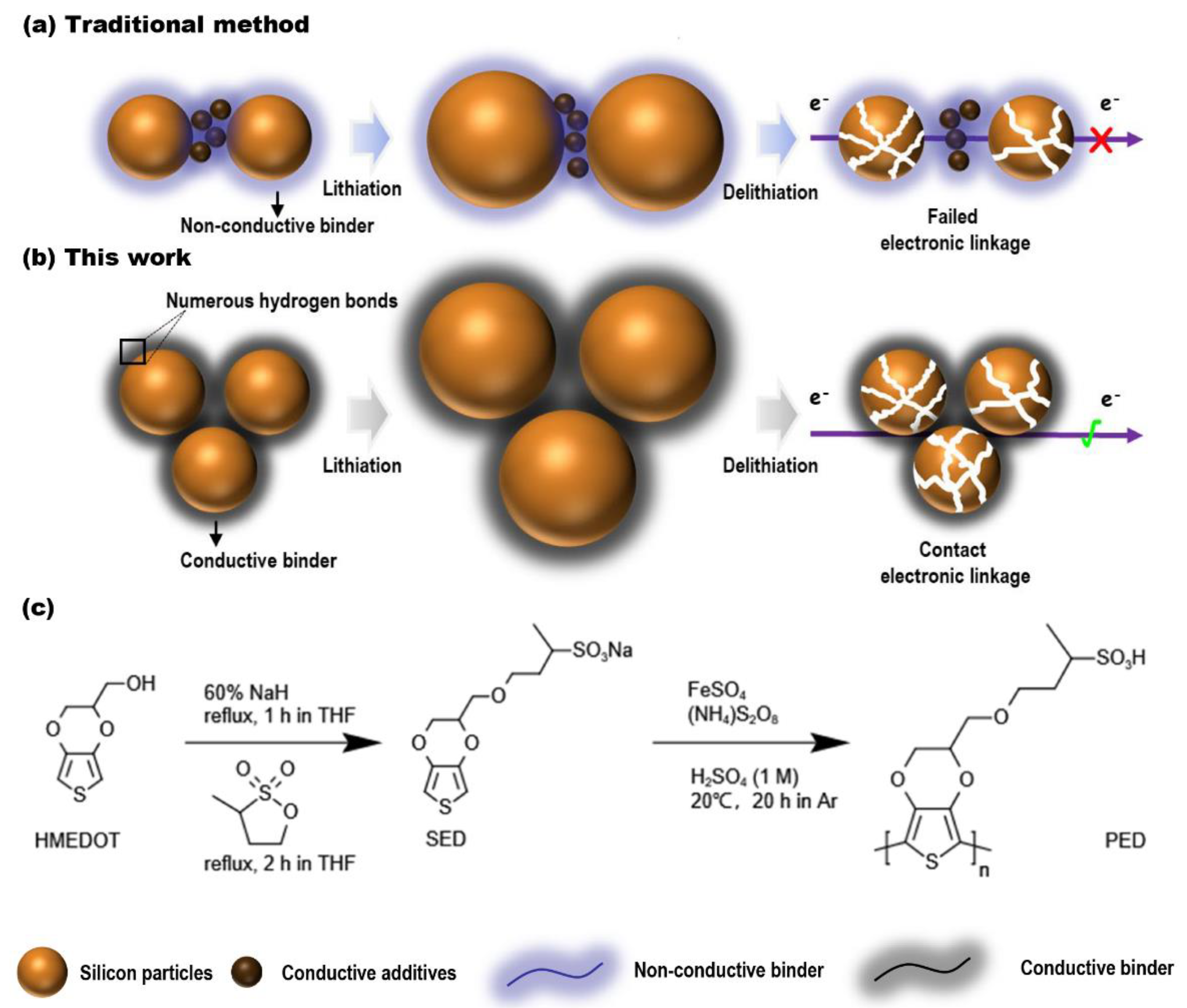
Figure 1. Schematic illustration of the structure of Si electrode during discharge and charge process. (a) Traditional method uses carbon black (CB) as the conductive additive and PVDF as binder, lead− ing to broken electric contacts; (b) novel approach uses conductive bifunctional binders com− posed of PED and PAA, which could maintain both the electrical and mechanical stability of the electrode during repeated charge/discharge cycles; (c) synthetic route to the PED.
Batteries 08 00054 g001
Figure 2. (a) The swelling ratios of different binders in the electrolyte; (b) 180° peeling test of PAA−PED−Si, PAA−CB−Si, and PVDF−CB−Si electrodes; (c) schematic illustration of peeling test and photos of the above electrodes after peeling (left) and active materials fallen off on tapes (right); (d) FT−IR spectra of PED, Si NPs, and mixture of both PED and Si NPs; (e) schematic illustration of the dual H−bond interactions between PAA/PED with Si NPs in the electrode.
Batteries 08 00054 g002
Figure 3. Electrochemical performances of Si−based electrodes. (a) The CV curves of the PAA−PED−Si electrode at a scanning rate of 0.2 mV s−1; (b) typical charging and discharging voltage profiles of the PAA−PED−Si, PAA−CB−Si, and PVDF−CB−Si electrodes at 420 mA g−1; (c) cycling performances of PAA−PED−Si, PAA−CB−Si, and PVDF−CB−Si electrodes in a voltage range from 0.01 to 1.5 V for 100 cycles at 1260 mA g−1; (d) rate performance of PAA−PED−Si electrode in the range of 0.1 C~1 C; (e) cycling performance of PAA−PED−Si electrode in a voltage range from 0.01 to 1.5 V over 200 cycles at 840 mA g−1; (f) EIS spectra of PAA−PED−Si electrode after 1st and 100th cycles; (g) EIS spectra of PAA−CB−Si electrode after 1st and 100th cycles; (h) impedance value of PAA−PED−Si and PAA−CB−Si electrode after 1st and 100th cycles.
Batteries 08 00054 g003
Figure 4. SEM characterization of the electrodes before and after cycling. (a,b) Top−view SEM images of PAA−PED−Si electrode before cycling ((b) is the amplified image of red box area in (a), the same below); (c,d) top−view SEM images of PAA−CB−Si electrode before cycling; (e) top−view SEM images of PAA−PED−Si after the 100th delithiation; (f) cross−sectional images of PAA−PED−Si before and after the 100th delithiation; (g) top−view SEM images of PAA−CB−Si after the 100th delithiation; (h) cross−sectional images of PAA−CB−Si before and after the 100th delithiation.
Batteries 08 00054 g004
Publisher’s Note: MDPI stays neutral with regard to jurisdictional claims in published maps and institutional affiliations.