2.1. Circuit Structure
As shown in
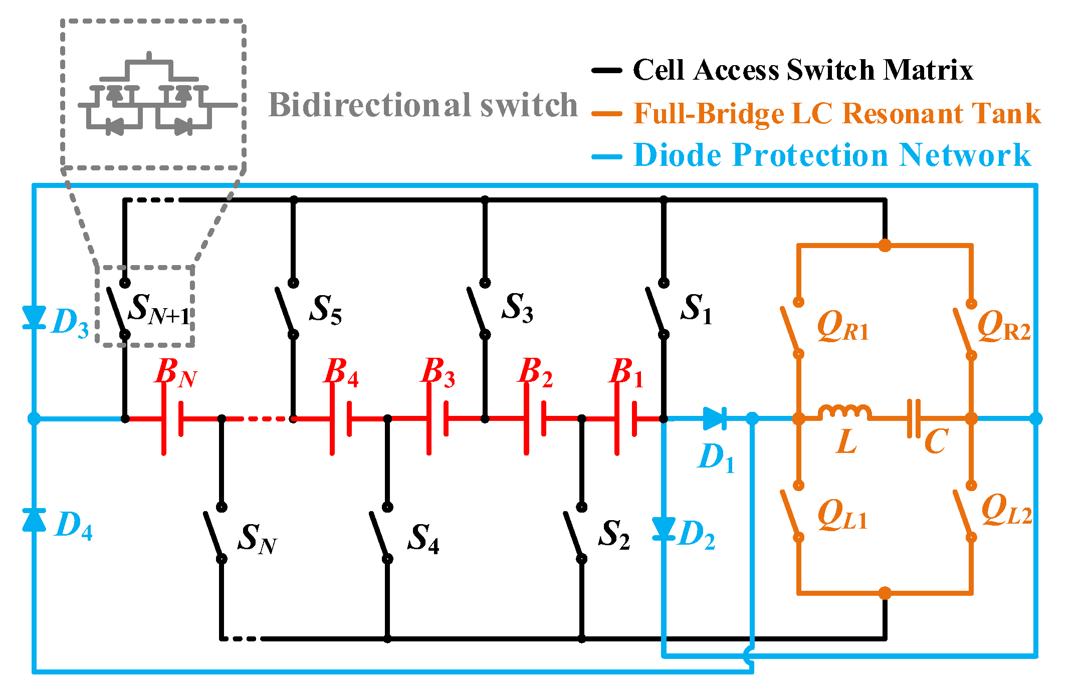
Figure 1, the proposed FBBRLCC equalizer has a cell access switch matrix, a full-bridge LC resonant tank, and a diode protection network. The cell access switch matrix consists of
N + 1 bidirectional switches (
S1 −
SN+1). The full-bridge LC resonant tank consists of a resonant tank and a full-bridge switch structure (
QR1,
QR2,
QL1,
QL2). The diode protection network consists of four free-wheeling diodes (
D1–
D4).
The resonant tank collects energy from the consecutive odd number of more-charged cells (release group) through the cell access switch matrix and the full-bridge switches (QR1, QR2, QL1, QL2), and then releases the energy to the consecutive odd number of less-charged cells (collect group).
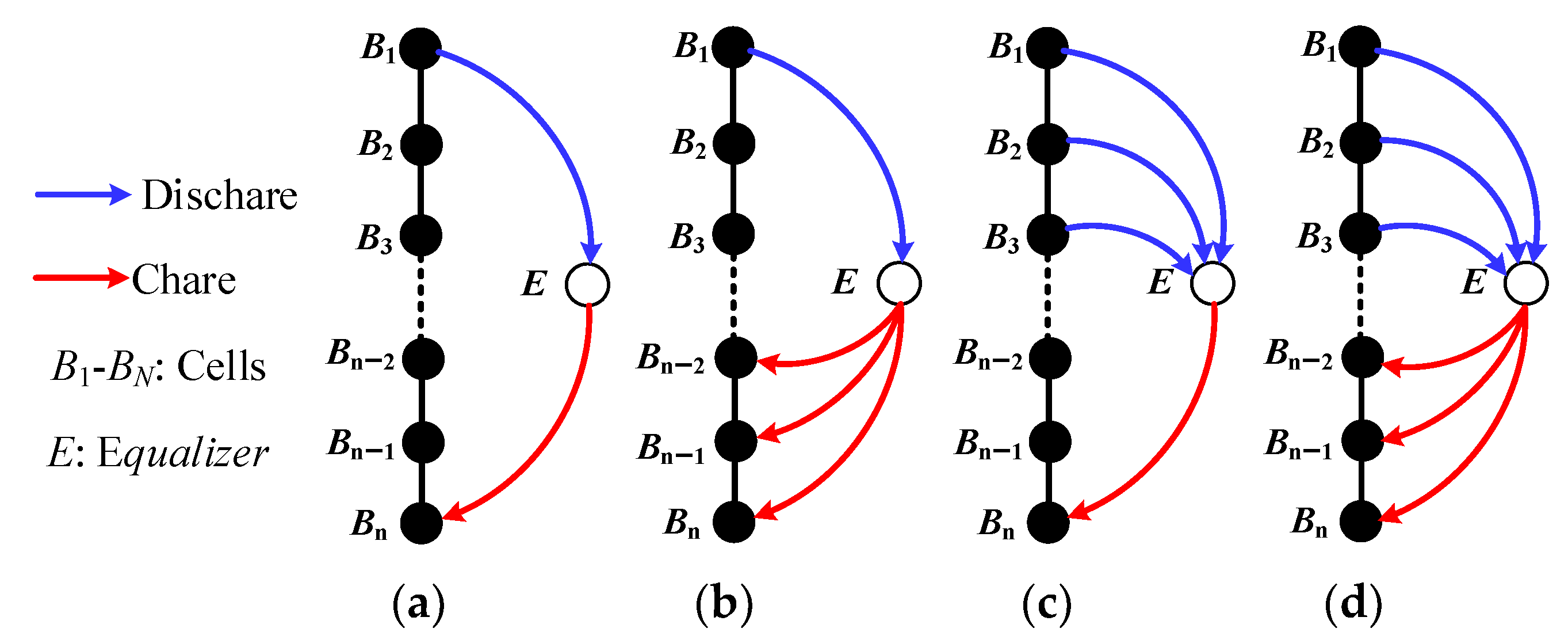
Figure 2 presents four potential operation modes including one-cell-to-one-cell mode (1-1 mode), one-cell-to-three-cell mode (1-3 mode), three-cell-to-one-cell mode (3-1 mode), and three-cell-to-three-cell mode (3-3 mode). Due to the circuit’s resonant nature, the driving signals’ switching frequency and duty cycle are fixed. As a result, it is possible to make a simple control. Meanwhile, all switches are controlled to work with zero-current switching (ZCS), which can reduce the switching loss and the electromagnetic interference (EMI) and help reduce circuit size by increasing switching frequency.
2.2. Operation Principle
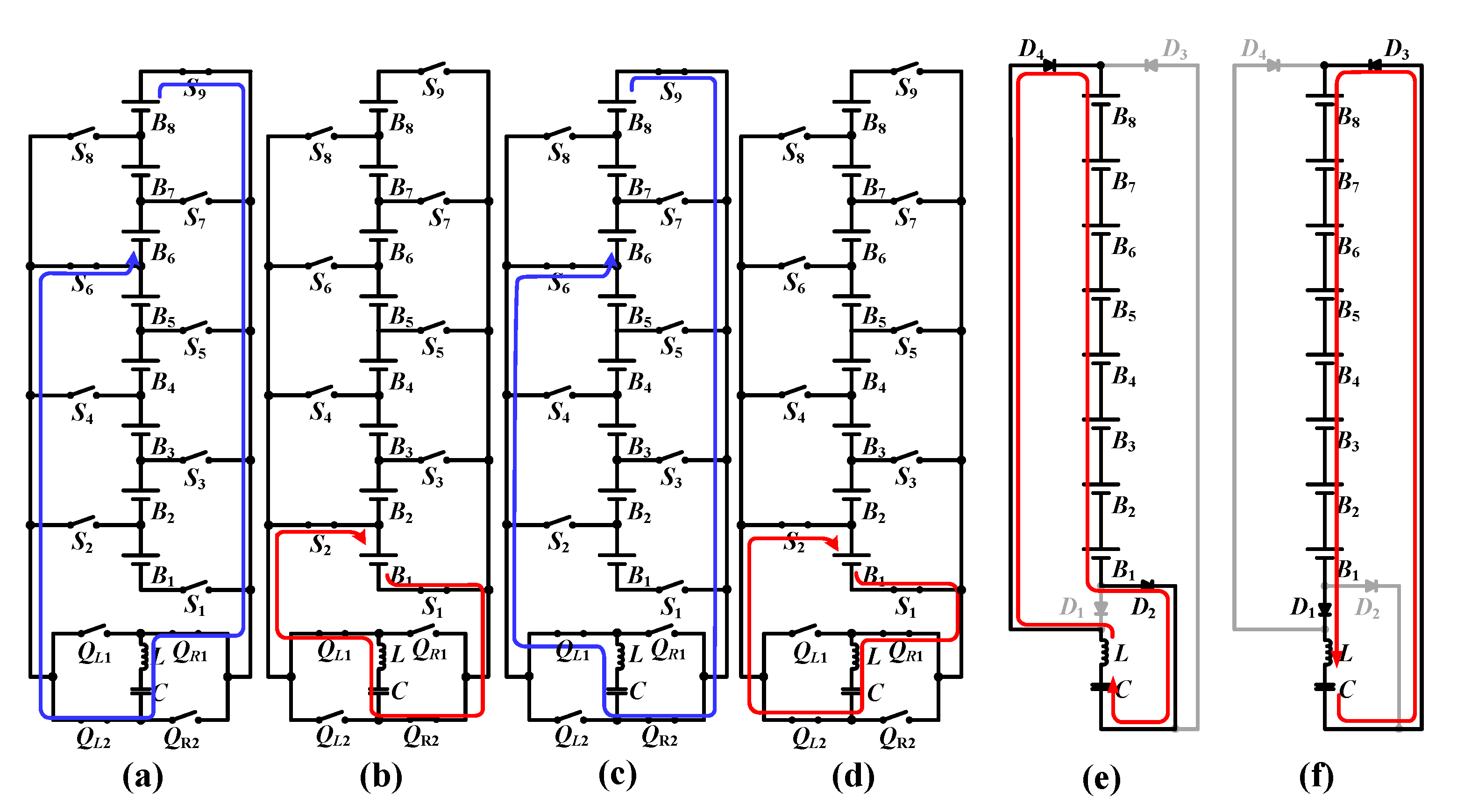
Figure 3 presents the operating states along with the current flow of the proposed equalizer. To facilitate the analysis, the balancing loop and the protection loop are analyzed separately, and it is assumed that the battery pack has eight cells with
VB8 =
VB7 =
VB6 >
VB5 >
VB4 >
VB3 >
VB2 >
VB1, which is arranged to illustrate the 3-1 mode equalization. The voltage of release group and collect group are
VBR =
VB8 +
VB7 +
VB6 and
VBC =
VB1, respectively.
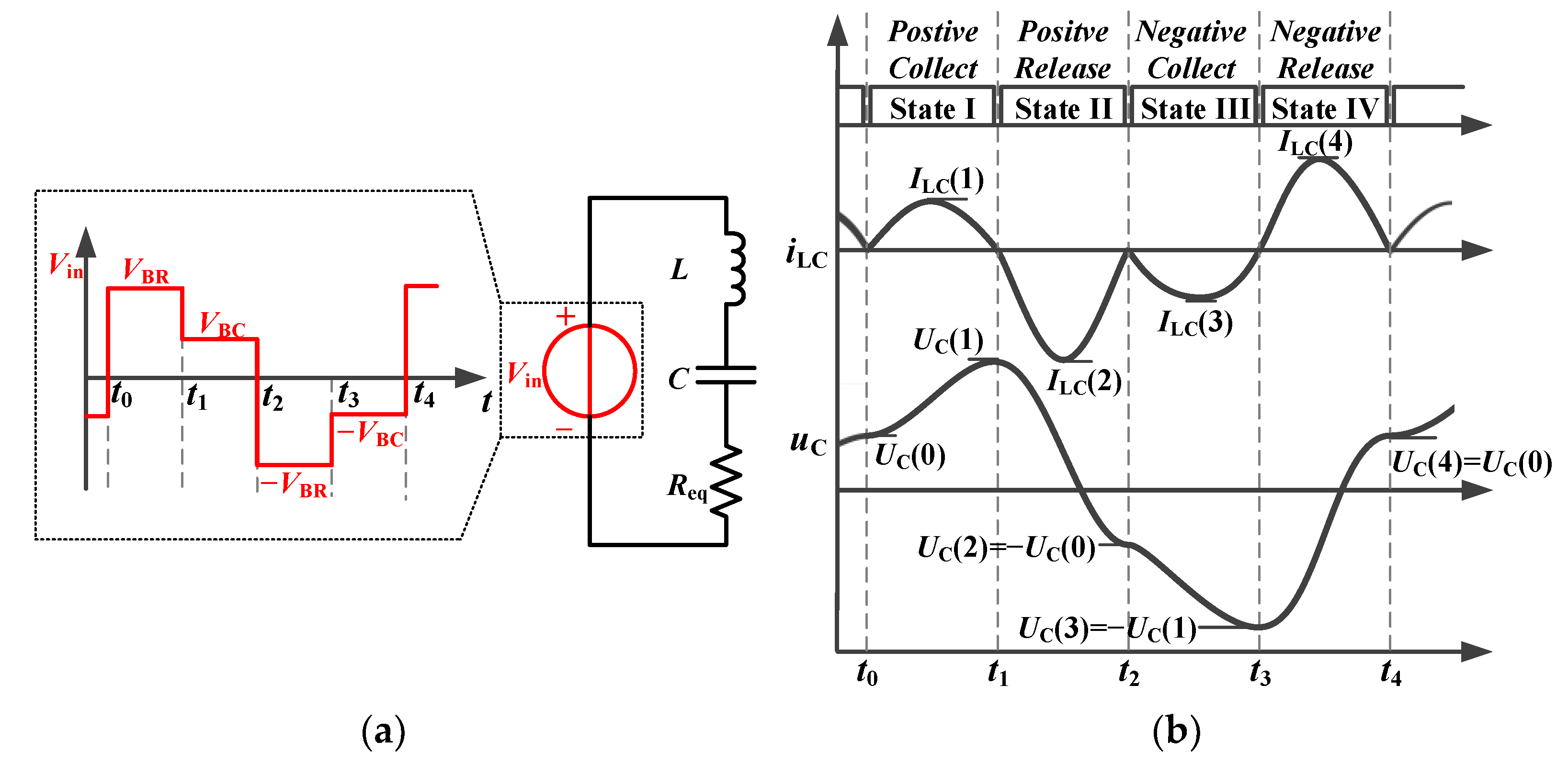
In
Figure 4a, an equivalent input of the full-bridge LC resonant converter is given.
Figure 4b shows the theoretical waveforms of the proposed equalizer at
VBR ≈ 3
VBC. In
Figure 4a, the
Req represents the total parasitic resistance and can be expressed as
Req =
RLC + 8
RON, where
RLC is the total resistance of the LC resonant tank and
RON is the ON-resistance of a MOSFET.
The proposed equalizer has a similar equivalent input to the bipolar-resonant LC converter (BRLCC) equalizer presented in [
21]. However, compared with the symmetrical switch matrix in [
21], the proposed equalizer achieves a change in the polarity of the input terminal through a full-bridge switch structure, which can reduce the number of switches by nearly half. As a result, the proposed equalizer not only achieves MC2MC equalization, but also greatly reduces the size of the circuit and improves the reliability of the circuit.
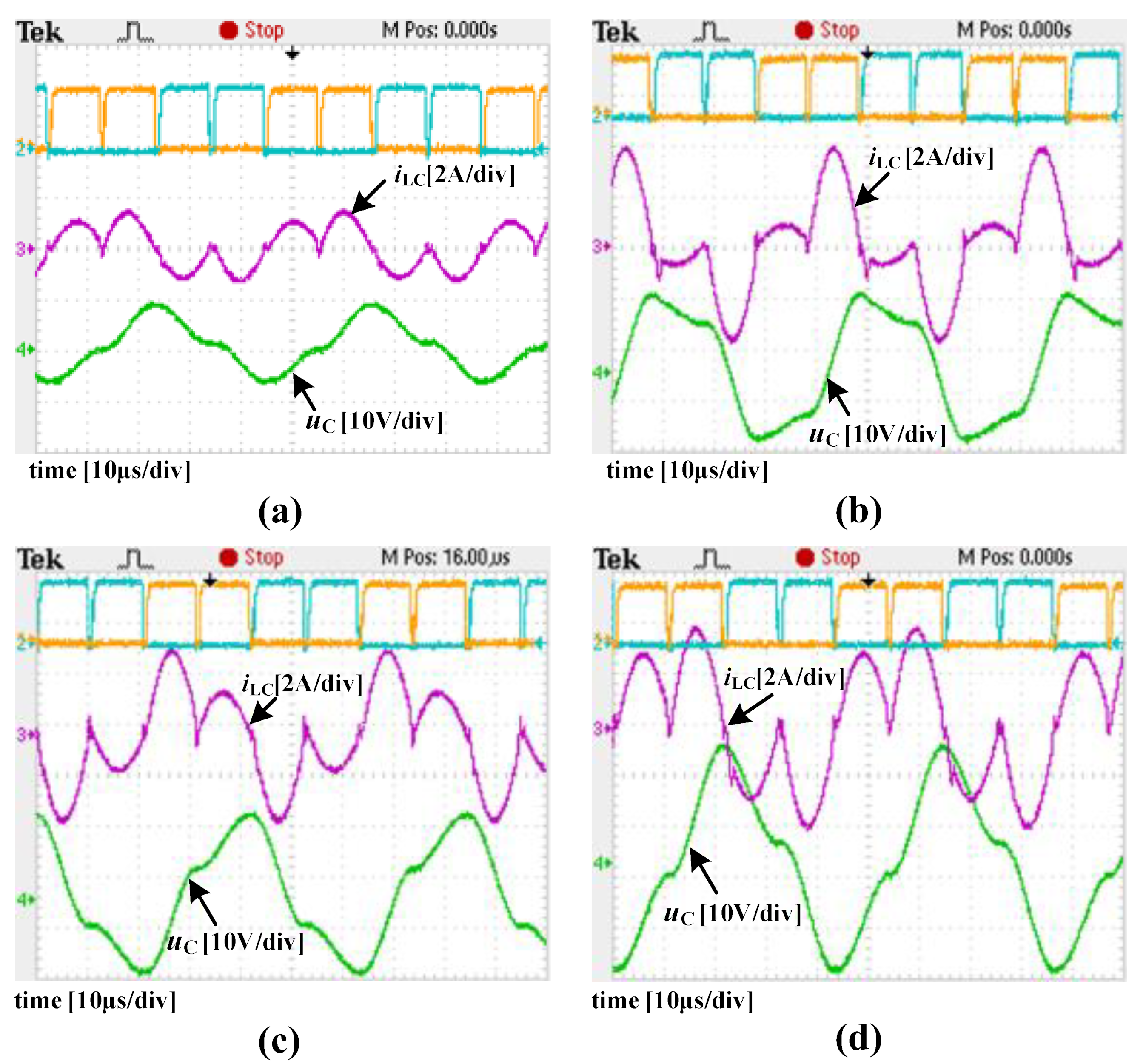
Figure 4b shows the waveforms including driving signals, inductor current
iLC, and capacitor voltage
uC of the equalizer, which shows the inductor current
iLC achieves ZCS by resonance, and the capacitor voltage
uC is charged/discharged to different voltage values at the end of each switching state. More details are described in
Section 2.3.
2.3. Mathematical Model
Based on the equivalent input of the full-bridge LC resonant converter and according to Kirchhoff’s voltage law,
uC and
iLC meet:
where
L is the inductance,
C is the capacitance,
Req is the total parasitic resistance.
In positive collect state I [
t0–
t1]: during this state, switches
S6 and
S9 connect the release group (
VBR =
VB8 +
VB7 +
VB6) to the full-bridge LC resonant tank. The LC resonant tank is charged positively using
QL2 and
QR1. Since
UC(0) is a remnant
uC from the previous period and is lower than
VBR,
uC increases from
UC(0) to
UC(1), and the peak value of
iLC is
ILC(1). According to (1),
uC and
iLC can be given by:
where
,
, and
. The positive collect state ends when
iLC reaches zero at
t =
t1, and the duration of this state is:
At the end of this state,
uC is positively charged to
UC(1):
In positive release state Ⅱ [
t1–
t2]: during this state, switches
S1 and
S2 connect the collect group (
VBC =
VB1) to the full-bridge LC resonant tank. The LC resonant tank positively releases charges to
VBC using
QL1 and
QR2. Since
UC(1) is higher than
VBC,
uC discharges from
UC(1) to
UC(2), and the peak value of
iLC is
ILC(2). In this state,
uC and
iLC can be given by:
At the end of this state,
iLC reaches zero at
t =
t2 =
t1 + Δ
t, uC is positively charged to
UC(2):
In negative collect state Ⅲ [
t2–
t3]: during this state, switches S
6 and S
9 connect the release group (
VBR =
VB8 +
VB7 +
VB6) to the full-bridge LC resonant tank. The LC resonant tank is charged negatively using
QL1 and
QR2. Since
UC(2) is negatively lower than −
VBR,
uC is negatively charged from
UC(2) to
UC(3), and the peak value of
iLC is
ILC(3). In this state,
uC and
iLC can be given by:
At the end of this state,
iLC reaches zero at
t =
t3 =
t1 + 2Δ
t,
uC is negatively charged to
UC(3):
By substituting t into Equations (9) and (10), it can be found that the waveforms in Equations (9) and (10) are identical to those in Equations (2) and (3) except for the polarity.
In negative release state Ⅳ [
t3–
t4]: during this state, switches
S1 and
S2 connect the collect group (
VBC =
VB1) to the full-bridge LC resonant tank. The LC resonant tank negatively releases charges to
VBC using
QL2 and
QR1. Since
UC(3) is negatively higher than −
VBC,
uC negatively discharges from
UC(3) to
UC(4), and the peak value of
iLC is
ILC(4). In this state,
uC and
iLC can be given by:
At the end of this state,
iLC reaches zero at
t =
t4 =
t2 + 2Δ
t,
uC negatively discharges to
UC(4):
By substituting t into Equations (12) and (13), it can be found that the waveforms in Equations (12) and (13) are identical to those in Equations (6) and (7) except for the polarity.
Based on Equations (5), (8), (11) and (14), the capacitor voltage
uC and peak inductor current
iL in each state can be calculated by combining
UC(0) =
UC(4):
where
According to the analysis above, the release group will charge the capacitor in positive collect state I and in negative collect state Ⅲ. As a result,
uC rises from
UC(0) to
UC(1) positively and rises negatively from
UC(2) to
UC(3). According to (15), it also should be noticed that
UC(0)–
UC(1) and
UC(2)–
UC(3) are equal. As the total duration of one switching period is 4Δ
t, the average power released by the release group can be expressed as:
Similarly, the capacitor will charge the collect group in positive release state II and in negative release state IV. As a result,
uC falls from
UC(1) to
UC(2) positively and falls negatively from
UC(3) to
UC(4). Therefore, the average power received by the collect group can be expressed as:
Based on (18) and (19), the balancing efficiency
ηFBBRLCC can be calculated as:
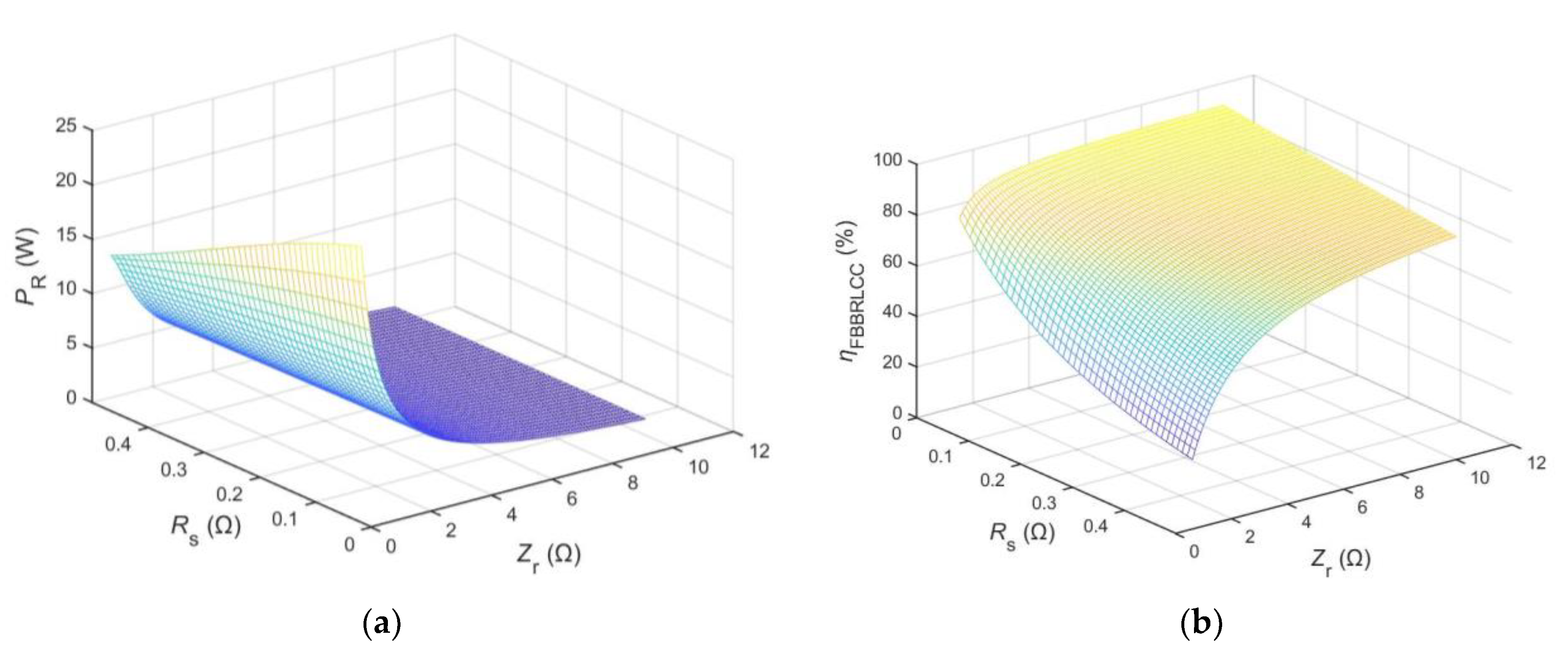
Based on Equations (18) and (20),
Figure 5a presents the average power
PR versus
Zr and
Req and
Figure 5b presents the balancing efficiency
ηFBBRLCC versus
Zr and
Req when
VBR = 12 V and
VBC = 3.9 V. From
Figure 5, we can observe that, as the total parasitic resistance
Req decreases, both the balancing efficiency
ηFBBRLCC and the average power
PR increase. As a result, the total parasitic resistance
Req should be minimized to achieve a maximum average power
PR and a maximum balancing efficiency
ηFBBRLCC. It can also be observed that, when the total parasitic resistance
Req is determined, a larger
Zr will result in a higher
ηFBBRLCC, while a smaller
Zr will result in a higher
PR, which can be used to adjust the average power and the balancing efficiency by changing
Zr.


