Article

Impact of Full Prelithiation of Si-Based Anodes on the Rate and Cycle Performance of Li-Ion Capacitors

1
Department of Electrical and Electronic Engineering, College of Engineering, Nihon University, Tokusada nakagawara 1, Tamuramachi, Koriyama 963-8642, Japan
2
Department of Mathematical Science and Electrical-Electronic-Computer Engineering, Akita University, Tegatagakuen-machi 1-1, Akita 010-8502, Japan
3
Joint Research Center for Electric Architecture, Akita University, Tegatagakuen-machi 1-1, Akita 010-8502, Japan
*
Author to whom correspondence should be addressed.
Batteries 2022, 8(6), 49; https://doi.org/10.3390/batteries8060049
Submission received: 23 April 2022 / Revised: 20 May 2022 / Accepted: 24 May 2022 / Published: 27 May 2022
(This article belongs to the Special Issue Li-Ion Capacitors: Materials, Devices and Systems)

Abstract

:
The impact of full prelithiation on the rate and cycle performance of a Si-based Li-ion capacitor (LIC) was investigated. Full prelithiation of the anode was achieved by assembling a half cell with a 2 µm-sized Si anode (0 V vs. Li/Li+) and Li metal. A three-electrode full cell (100% prelithiation) was assembled using an activated carbon (AC) cathode with a high specific surface area (3041 m2/g), fully prelithiated Si anode, and Li metal reference electrode. A three-electrode full cell (87% prelithiation) using a Si anode prelithiated with 87% Li ions was also assembled. Both cells displayed similar energy density levels at a lower power density (200 Wh/kg at ≤100 W/kg; based on the total mass of AC and Si). However, at a higher power density (1 kW/kg), the 100% prelithiation cell maintained a high energy density (180 Wh/kg), whereas that of the 87% prelithiation cell was significantly reduced (80 Wh/kg). During charge/discharge cycling at ~1 kW/kg, the energy density retention of the 100% prelithiation cell was higher than that of the 87% prelithiation cell. The larger irreversibility of the Si anode during the initial Li-ion uptake/release cycles confirmed that the simple full prelithiation process is essential for Si-based LIC cells.

1. Introduction

The development of capacitor-based energy storage technology that can compensate for the shortcomings of secondary batteries, such as low power density, limited cycle life, restriction of excessive discharge, and high cost, is underway. Electric double-layer capacitors (EDLCs) have been used as high-power and long-life energy storage devices in electronic, automobile, energy-harvesting, and power-leveling/backup applications; however, they have the disadvantage of low energy density. Activated carbons (ACs) have generally been used as active materials in EDLC electrodes because they can achieve a larger surface area on the electrode, and thereby produce a wider electric double layer between the electrode and the electrolyte. Li-ion capacitors (LICs) are recognized as promising energy storage devices to overcome the low energy density of EDLCs while maintaining the high power density and long cycle life of capacitors. The higher energy density of LICs is due to an increased cell voltage (~4 V), which is attributed to low and narrow variation in the anode potential during charge/discharge cycling [1]. In LICs, the anode potential has previously been lowered by doping Li ions into the anode active material at a designed quantity, known as the prelithiation or predoping process. Thus, for LIC cell assembly, the prelithiation process is generally essential to decrease the initial potential of the anode [2].
During the initial Li-ion insertion/extraction cycles within the anode active material, an irreversible capacity may occur via the formation of a solid electrolyte interphase (SEI) on its surface and/or the passivation of Li ions within its bulk, which consumes Li ions dispersed in the electrolyte. In addition to the primary role of lowering the initial potential of the anode, the prelithiation process also has the important function of removing the irreversible capacity of the anode [3,4,5]. Prelithiation methods can generally be divided into short-circuit and electrochemical prelithiation strategies [4,5]. Another prelithiation method using stabilized Li metal powder (SLMP) has also been proposed. However, the manufacturing cost of SLMP is much higher than that of untreated Li foil, and the understanding of SEI formation, safety, and aging behavior for cathodes that have been prelithiated using SLMP is insufficient [4]. The short-circuit prelithiation method is performed by placing the anode with Li metal in direct contact with an electrolyte that contains Li ions [6] or by shorting two terminals that are individually connected to the anode and Li metal, both of which are saturated with a Li-ion-dispersed electrolyte and installed in a common cell. This method has the advantages of simplicity and easy scale-up; however, it is difficult to control the quantity of Li ions inserted into the anode (that is, the degree of prelithiation) [7,8]. For the electrochemical prelithiation method, the two terminals previously described and a battery testing machine are used, and Li ions are doped into the anode under controlled current conditions inside the cell. By monitoring the potential between the anode and Li metal, as well as the charge quantity (time integral of current) spent for the insertion of Li ions, the level of prelithiation can be accurately adjusted. However, this method is not suitable for the mass production and low-cost fabrication of LIC cells.
Various anode active materials, including metal oxides (e.g., Mn oxides and Fe oxides), carbonaceous materials (e.g., graphite and porous carbon), Ge, and Sn, have been applied in Li-ion batteries [9,10,11]. For LICs, graphite, hard carbon, and Li4Ti5O12 have been used as conventional anode active materials [12,13,14]. An increased quantity of Li ions doped into the anode reduces the anode potential, thereby increasing the cell voltage. However, excessive doping of Li ions into the anode can produce excessive Li metal deposition or Li passivation within the anode, thereby deteriorating the cycle performance of the LIC cell [15]. Therefore, prelithiation exceeding the theoretical specific capacity of the anode active material is not preferred. The optimum prelithiation degree for the graphite anode in LIC cells has been reported to be 70–80%, which refers to the theoretical specific capacity of graphite (372 mAh/g) [16]. Moreover, it has been reported that the suitable prelithiation degree for the Li4Ti5O12 anode in LIC cells is in the range of 34–102 mAh/g, which corresponds to 20–59% of its theoretical specific capacity (173 mAh/g) [17]. In addition to the theoretical specific capacity of the anode active material, the working cell voltage range and active mass ratio of the cathode to the anode should be considered to avoid exceeding the theoretical capacity of the anode [5,15,18].
Si has attracted considerable attention as an LIC anode active material because of its very high specific capacity with regard to Li-ion insertion/extraction (3580 mAh/g at room temperature, 10 times higher than that of graphite) [19,20,21]. The use of Si has the advantage of increasing the energy density of assembled LIC cells, thus enabling cell miniaturization. However, the Si anode suffers from extreme volumetric expansion during Li-ion uptake and release (~280% [22]), which causes the cracking of Si particles coated on the Cu current collector with an added binder and carbonaceous conductive agent [23]. This cracking may produce new interfaces between the electrolyte and opened cracks, which allows the reformation of SEI films and, thus, the consumption of Li ions. Furthermore, it weakens physical adhesion between Si particles, conductive agent particles, and the current collector, which increases the internal anode resistance [24,25,26]. The gradual loss of Li ions and increase in internal resistance may reduce the cycle stability of LIC cells. Using polyimide as an anode binder, Eguchi et al. developed a Si-based LIC that maintained 88% of its initial cell capacity after 2000 charge/discharge cycles in the cell voltage range of 2.0–4.0 V [27]. However, the appropriate prelithiation degree for Si-based anodes was not mentioned. Good cycle performance for an assembled full cell was achieved by using rice-husk-derived C/SiOx as the LIC anode active material and applying a short-circuit prelithiation process by shorting the half cell composed of SiOx and Li metal for 24 h, without the extraction of excessive Li ions [28]. Therefore, it may be convenient to enhance the productivity of LIC cells by subjecting the Si-based anode to a simple prelithiation process, either through short-circuit prelithiation or by simply decreasing the Si anode potential to 0 V vs. Li/Li+.
The prelithiation process is vital in LIC cell assemblies because it has a large impact on various cell performance characteristics, such as cell capacitance, internal resistance, energy and power density, rate capability, and cycle stability [4,5]. In this study, a Si-based anode that was fully lithiated by lowering the potential to 0 V vs. Li/Li+ in a half-cell configuration was incorporated into a three-electrode full cell with an AC cathode (hereafter defined as 100% prelithiation cell), which provided variations in cathode and anode potentials during the rate and cycle tests. A three-electrode full cell was also assembled using a Si-based anode in which 87% of Li ions used for the full prelithiation cell was inserted (defined as the 87% prelithiation cell), and its rate and cycle performance was compared with that of the 100% prelithiation cell. Subsequently, the influence of excessive Li ions, provided by prelithiation, on the rate and cycle performance of the LIC cells was evaluated based on the performance comparison. Using electrochemical impedance spectroscopy (EIS), resistive and capacitive components produced in the LIC cells were also evaluated.

2. Results and Discussion

2.1. Prelithiation of Si Anode

For LIC cell assembly at different degrees of prelithiation, Li ions were galvanostatically inserted into the Si anodes in the half-cell configuration. Figure 1 shows the potential–specific capacity profiles of the Si anodes during the prelithiation process. To prepare the 100% prelithiated Si anode, the Li-ion insertion specific capacity was 3461 mAh/g-Si. For the 87% prelithiated Si anode, Li-ion insertion was permitted up to a specific capacity of 3022 mAh/g-Si (87% of 3461 mAh/g-Si) at 0.037 V vs. Li/Li+. Thus, the margin for the 87% prelithiated Si anode to reach the maximum specific capacity was 439 mAh/g-Si. In contrast, the specific capacity of the AC cathode, which required an increase in the potential from 3.0 to 4.0 V vs. Li/Li+ in the half-cell configuration, was 58 mAh/g-AC [28]. Assuming the initial potentials of the Si anode and AC cathode were 0 and 3.0 V vs. Li/Li+, respectively, and the mass ratio of AC to Si was 3.9 in the LIC full-cell assembly, the quantity of Li ions inserted into the Si anode at the maximum cell voltage (4.0 V) was estimated to be 226 (= 3.9 × 58) mAh/g-Si. Thus, in the fully charged state (4.0 V), the Si anode in the 100% prelithiation cell should accommodate excess Li ions of 226 mAh/g-Si (6.5% of 3461 mAh/g-Si), while the Si anode in the 87% prelithiation cell has a margin of 213 mAh/g-Si (6.2% of 3461 mAh/g-Si) to achieve the maximum specific capacity.

2.2. Rate Capability of LIC Cells

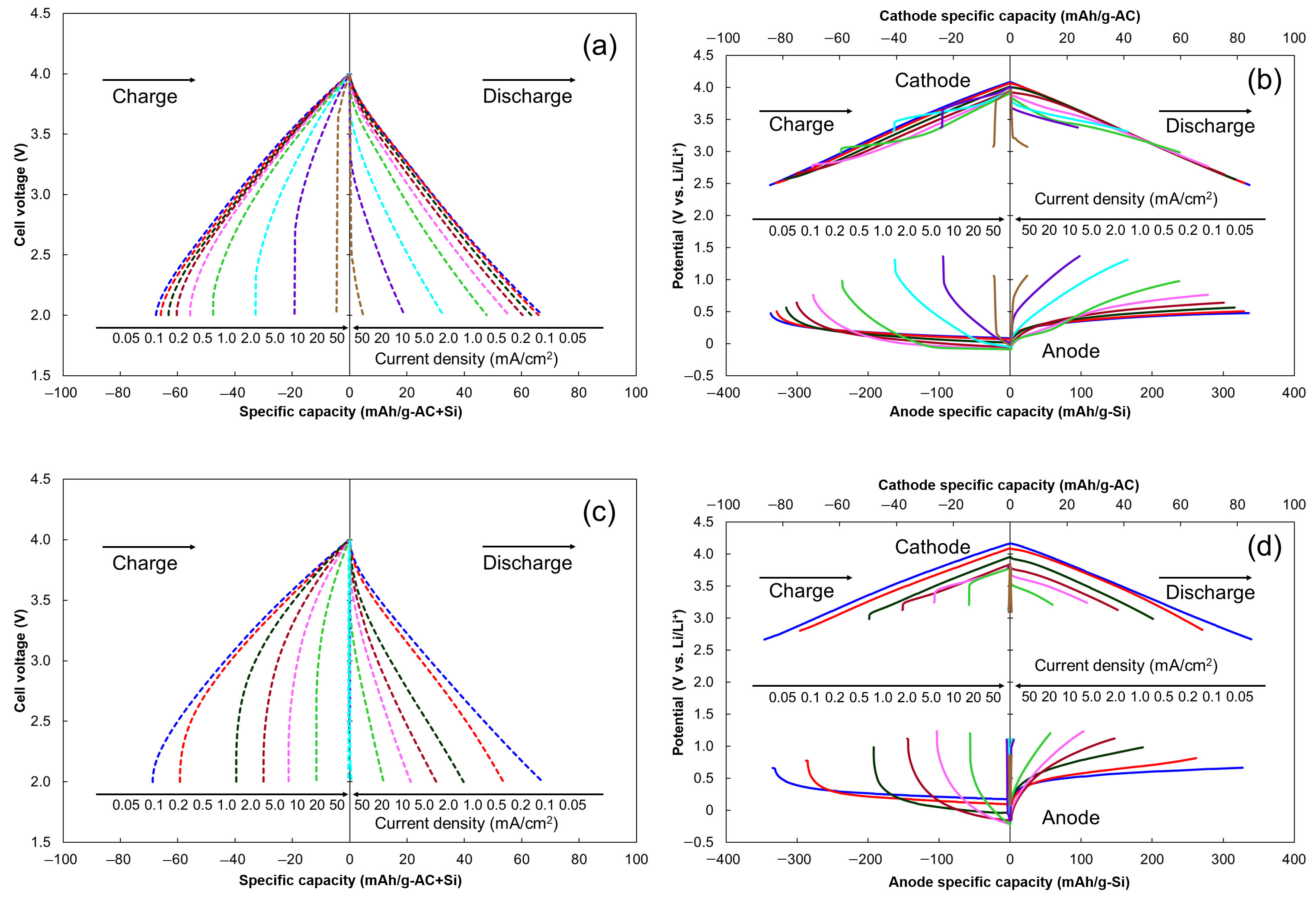
Three-electrode systems composed of 100% and 87% prelithiation LIC cells were repeatedly charged and discharged at different current densities, and variations in the potentials of the AC cathode and Si anode were recorded. Figure 2 shows the cell voltage–specific capacity profiles and the potential variations in the cathode and anode for the two cells. During initial charging at the lowest current density of 0.05 mA/cm2, specific capacities of 70.0 and 79.1 mAh/g-AC + Si were required for the 100% and 87% prelithiation cells, respectively. The cathode potential of the 100% prelithiation cell increased from 2.45 to 4.09 V vs. Li/Li+ with a cathode specific capacity of 88 mAh/g-AC, whereas that of the 87% prelithiation cell increased from 2.56 to 4.21 V vs. Li/Li+ with a cathode specific capacity of 99 mAh/g-AC. The anode potential of the 100% prelithiation cell decreased from 0.45 to 0.09 V vs. Li/Li+ with an anode specific capacity of 349 mAh/g-Si, whereas that of the 87% prelithiation cell decreased from 0.55 to 0.21 V vs. Li/Li+ with an anode specific capacity of 376 mAh/g-Si. During the discharge process at 0.05 mA/cm2, the 100% and 87% prelithiation cells exhibited specific capacities of 68.7 and 73.7 mAh/g-AC + Si, respectively, corresponding to charge/discharge Coulombic efficiencies of 98.1% and 93.2%, respectively. The Coulombic efficiency was lower than 100%, indicating that irreversible capacities occurred for the cells resulting from the loss of electrolytic ions or decomposition of the electrolyte solvent. After the discharge process, the cathode potential of the 100% prelithiation cell decreased to 2.46 V vs. Li/Li+ (86 mAh/g-AC), whereas that of the 87% prelithiation cell decreased to 2.59 V vs. Li/Li+ (93 mAh/g-AC). The 100% and 87% prelithiation cells permitted increases in anode potentials to 0.46 V vs. Li/Li+ (343 mAh/g-Si) and 0.58 V vs. Li/Li+ (350 mAh/g-Si), respectively. Therefore, the full prelithiation process was demonstrated to be beneficial for achieving reduced anode and cathode potentials (~0.1 V decrement).
Increasing the current density during the charge/discharge processes reduced the cell specific capacities of the 100% and 87% prelithiation cells. Notably, a larger decrease in cell specific capacity was observed for the 87% prelithiation cell. Distinct differences in the cell voltage and potential variations between the 100% and 87% prelithiation cells were observed at a current density of 1.0 mA/cm2. For the discharge process at 1.0 mA/cm2, the specific capacities of the 100% and 87% prelithiation cells were 60.3 and 30.1 mAh/g-AC + Si, respectively. The cathode potential of the 100% prelithiation cell decreased from 3.95 to 2.64 V vs. Li/Li+ with a specific capacity of 75 mAh/g-AC, whereas the anode potential of the 100% prelithiation cell increased from −0.05 to 0.64 V vs. Li/Li+ with a specific capacity of 301 mAh/g-Si. For the 87% prelithiation cell, a decrease in the cathode potential from 3.84 to 3.13 V vs. Li/Li+ with a specific capacity of 38 mAh/g-AC and an increase in the anode potential from −0.16 to 1.12 V vs. Li/Li+ with a specific capacity of 147 mAh/g-Si were observed. Notably, the cell, cathode, and anode specific capacities of the 87% prelithiation cell were halved compared with those of the 100% prelithiation cell at 1.0 mA/cm2. At current densities higher than 5 mA/cm2, the specific capacity of the 87% prelithiation cell was negligible. Both the cell voltage–specific capacity profiles displayed sharp voltage increases/decreases during the initial stage of the charge/discharge process at ≥1.0 mA/cm2, and relatively larger increases and decreases were observed for the 87% prelithiation cell. The cathode and anode potential variations indicated that larger voltage increases/decreases were associated with the anode. Therefore, compared with shallow prelithiation, the full prelithiation process was found to be useful for reducing the internal resistance produced within Si-based LIC cells.
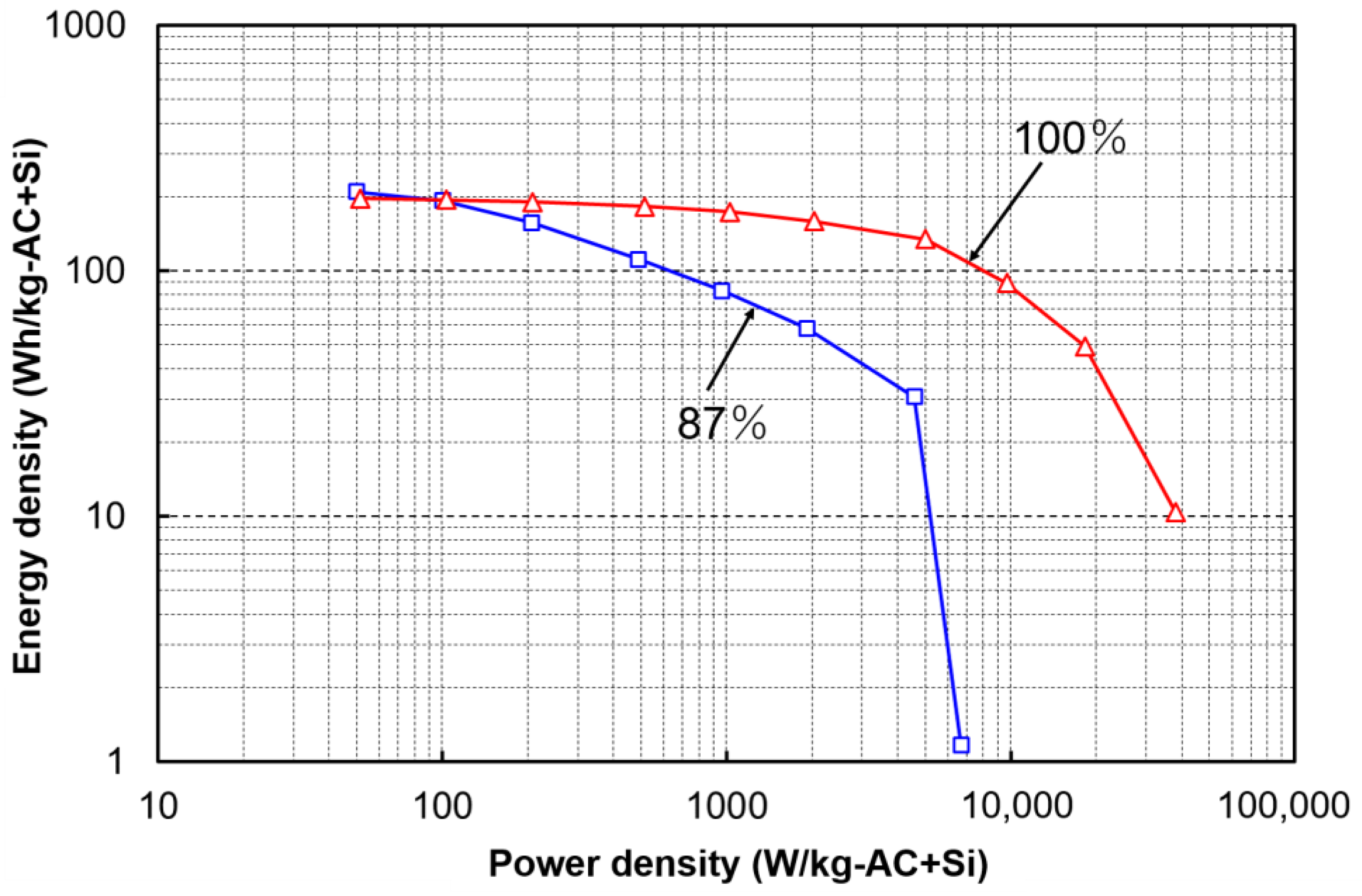
Ragone plots (energy density vs. power density) of the two cells are shown in Figure 3. Both cells exhibited a high energy density of 200 Wh/kg-AC + Si at lower power densities (≤100 W/kg-AC + Si). At higher power densities, the energy density retention of the 100% prelithiation cell was greater than that of the 87% prelithiation cell. At a power density of 1 kW/kg-AC + Si, the 100% prelithiation cell maintained an energy density of 180 Wh/kg-AC + Si, whereas the energy density of the 87% prelithiation cell decreased to 100 Wh/kg-AC + Si. At a very high power density of >5 kW/kg-AC + Si, the energy density of the 87% prelithiation was significantly low. All the rate test results demonstrated that full prelithiation of the Si anode contributed to an enhancement of the rate capability of Si-based LIC cells. Conversely, the shallow prelithiation process promoted a reduction in the rate capability under high-power-density operation.

2.3. Impedance Analysis

Following the rate test, the impedance spectra of the 100% and 87% prelithiation cells in the fully charged state (DC bias voltage: 4.0 V) were measured, as shown in Figure 4, and analyzed according to a previously reported equivalent circuit that simulates the operation of LIC cells [29]. This equivalent circuit can be applied to the typical impedance spectra of LIC cells, which have two semicircles (resulting from two parallel connections of a constant phase element (CPE) and resistance) and a straight line (resulting from diffusion resistance). The CPEs in the equivalent circuit are used to represent the nonideal capacitive behavior of the cell elements, which is associated with distributed reactivity, inhomogeneity, porosity and surface roughness of electrodes, and current and potential distributions [30]. In Figure 4, Rs is the electrolyte resistance; RSEI and CPESEI correspond to the resistance and nonideal capacitance of the SEI formed on the Si anode, respectively; RC and CPEC correspond to the resistance and nonideal capacitance resulting from electron transfer at and on the electrodes, respectively; and W is the diffusion resistance (Warburg impedance), which has nonlinear behavior owing to the transport kinetics of ions. Pairs of compressed semicircles were detected in the impedance spectra of the 100% and 87% prelithiation cells, shown in the magnified inset, at lower frequencies (<63 and <50 Hz, respectively). The real part of the impedance at the end of the second semicircle, which corresponds to the sum of RS, RSEI, and RC, was determined to be 5.4 and 14.2 Ω for the 100% and 87% prelithiation cells, respectively. At these frequencies, both cells displayed approximately linear variations, which were caused by the ion-diffusion resistance at the interface between the electrolyte and electrodes and within the electrodes. The total resistance (RS, RSEI, RC, and ion diffusion) of the 87% prelithiation cell was significantly higher than that of the 100% prelithiation cell, which is consistent with the larger increases/decreases in cell voltage observed during the initial stage of the charge/discharge process in the rate test.

2.4. Cycle Stability of LIC Cells

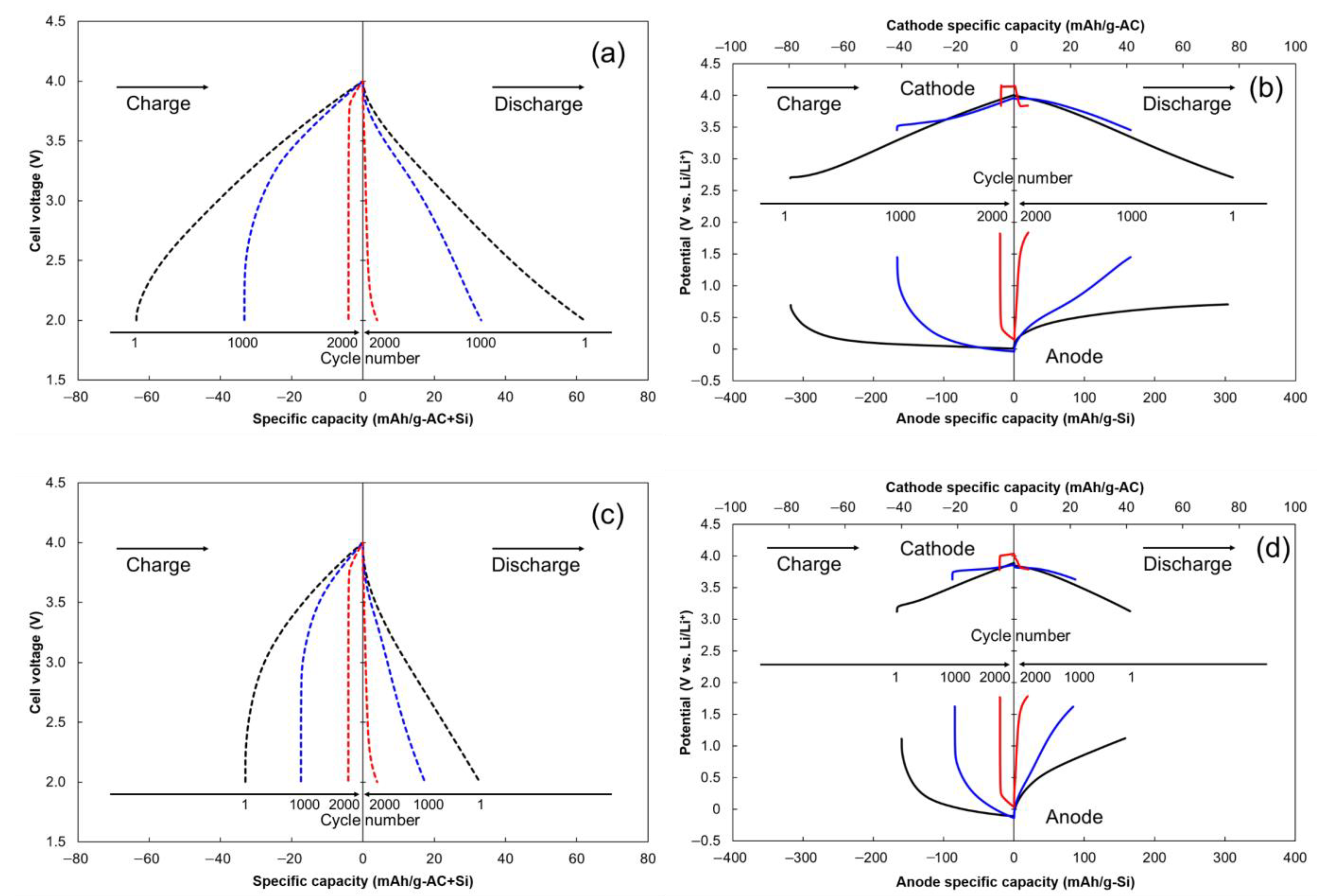
A cycle test was performed for the 100% and 87% prelithiation cells at a constant current density of 1.0 mA/cm2, corresponding to a power density of approximately 1 kW/kg-AC + Si. Figure 5 shows the cell voltage and the cathode and anode potential profiles of the LIC cells at the 1st, 1000th, and 2000th cycles. During the earlier cycles, the 100% prelithiation cell showed a higher cell specific capacity than the 87% prelithiation cell. The cell specific capacities of the charge and discharge processes during the 1st cycle for the 100% prelithiation cell were 63.6 and 62.0 mAh/g-AC + Si (97.5% Coulombic efficiency), respectively, whereas those of the 87% prelithiation cell were 33.0 and 32.8 mAh/g-AC + Si (99.4%), respectively. Notably, even after the rate test, the 100% prelithiation cell maintained an irreversible capacity. As the number of cycles increased, the specific capacity of both cells decreased, and a larger increase/decrease in the cell voltage was observed during the initial stage of the charge/discharge process. During the 1st charge/discharge cycle, the cathode potential of the 100% prelithiation cell increased from 2.70 to 4.01 V vs. Li/Li+ (80 mAh/g-AC) and then decreased to 2.71 V vs. Li/Li+ (78 mAh/g-AC), whereas its anode potential decreased from 0.70 to 0.01 V vs. Li/Li+ (318 mAh/g-Si) and then increased to 0.71 V vs. Li/Li+ (310 mAh/g-Si). For the 87% prelithiation cell, the cathode potential increased from 3.12 to 3.89 V vs. Li/Li+ (42 mAh/g-AC) and then decreased to 3.13 V vs. Li/Li+ (41 mAh/g-AC). The anode potential decreased from 1.11 to −0.11 V vs. Li/Li+ (160 mAh/g-Si) and then increased to 1.12 V vs. Li/Li+ (158 mAh/g-Si). Based on the approximately linear variation in the cathode potential for both cells, the potential variations in the Si anodes were likely responsible for the nonlinearity of the cell voltage variations. Because of the lower specific capacity of the Si anode at higher potentials (>0.5 V vs. Li/Li+), the 87% prelithiation cell barely accepted outward current during the initial charging state (2.0–2.5 V). As the number of charge/discharge cycles increased, the specific capacity of the Si anodes in both cells decreased, whereas the potential increased. After the 1000th cycle, the Si anode in the 100% prelithiation cell exhibited a decreased specific capacity (166 mAh/g-Si) and elevated potential (1.45 V vs. Li/Li+) when the discharge process was complete. After the 2000th cycle, the two cells exhibited similar cell voltage and cathode and anode potential profiles, which suggested that a complete loss of the Li-ion uptake and release function occurred in both Si anodes.
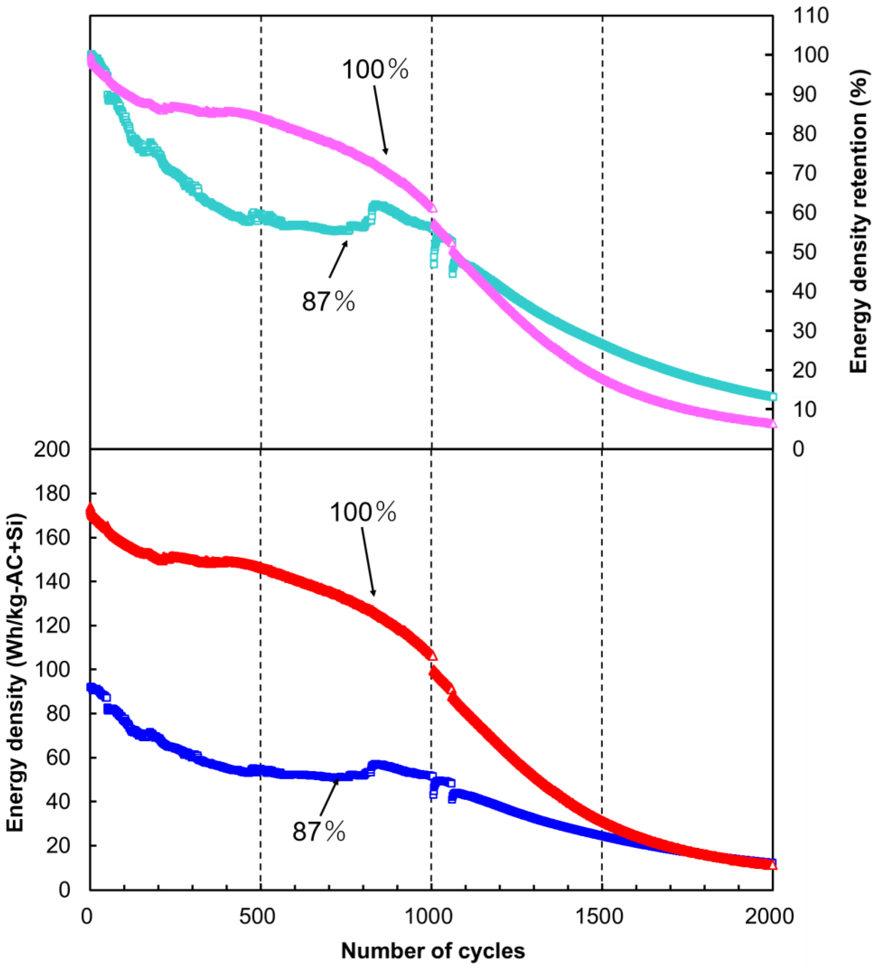
Figure 6 shows the energy densities and energy density retention of the LIC cells during the cycle test. The initial energy densities of the 100% and 87% prelithiation cells were 174 and 92 Wh/kg-AC + Si, respectively. Up to the 1500th cycle, the 100% prelithiation cell maintained an energy density higher than that of the 87% prelithiation cell. Subsequently, both cells exhibited a similar energy density, which was reduced to <20 Wh/kg-AC + Si. The energy density retention was also higher for the 100% prelithiation cell up to the 1000th cycle. After the 1000th cycle, the 100% prelithiation cell exhibited a large decrease in energy density retention. The anode potential profile of the 100% prelithiation cell (Figure 5b) indicated that the Si anode allowed a large decrease in the specific capacity (approximately halved by the 1000th cycle). When the cell was fully discharged, the Si anode displayed the highest potential of >1.5 V vs. Li/Li+. This behavior is likely related to the progression of Si particle pulverization and exfoliation resulting from the cyclic volume changes associated with Li-ion uptake and release. The final energy density retentions of the 100% and 87% prelithiation cells were 6.4% and 13.2%, respectively. The cycle test results demonstrated that full prelithiation of the Si anode improved the cycle stability of LIC cells, although the impact was limited to ~1000 cycles.

2.5. Impact of Anode Full Prelithiation in Si-Based LICs

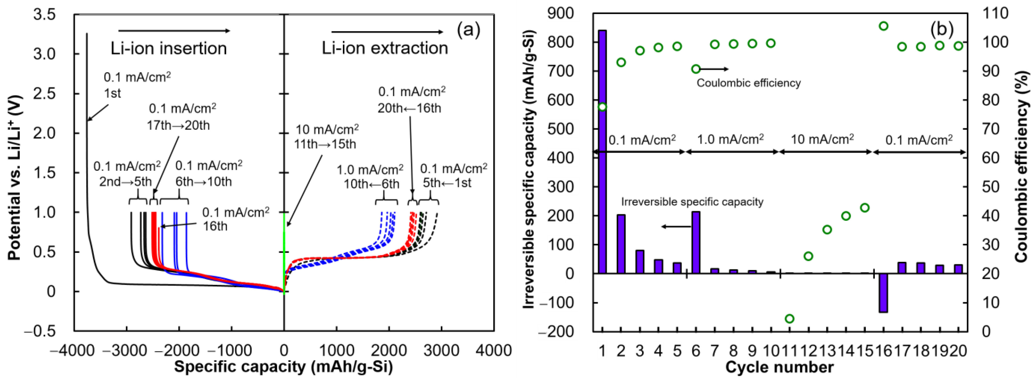
The rate and cycle test results clearly revealed that full prelithiation of the Si anode, with the potential lowered to 0 V vs. Li/Li+, was effective in enhancing the rate and cycle performance of the assembled LIC cell, as compared with conventional prelithiation with marginal Li-ion uptake to restrict metallic Li formation. At the highest cell voltage of 4.0 V, the 100% prelithiation cell was designed to accept excess Li ions (6.5% of the maximum anode capacity), whereas the 87% prelithiation cell had a Li-ion acceptance that was 6.2% of its maximum anode capacity. The superior rate and cycle performance of the 100% prelithiation cell indicated that the excess inserted Li ions were consumed during the initial charge/discharge cycles. As mentioned above, Si is susceptible to particle cracking during the Li-ion insertion and extraction cycles, which produces successive SEI layers and thereby causes the loss of Li ions from the electrolyte. In this study, the alleviation of Si particle cracking was attempted using a polyimide binder. To investigate the Li-ion consumption behavior of the Si anode, its fundamental cyclic Li-ion uptake and release properties were evaluated in the half-cell configuration. Figure 7 shows the potential–specific capacity profile, irreversible specific capacity, and Coulombic efficiency of the Si anode during stepwise variation of the applied current density. The first Li-ion insertion into the Si anode required a specific capacity of 3760 mAh/g-Si to decrease the potential from 3.26 to 0 V vs. Li/Li+, and the first Li-ion extraction required a specific capacity of 2919 mAh/g-Si to restore the potential to 1.0 V vs. Li/Li+. Thus, the Coulombic efficiency and irreversible specific capacity of the first Li-ion insertion/extraction cycle were 77.6% and 841 mAh/g-Si, respectively. During successive Li-ion insertion/extraction cycles, the irreversible specific capacity did not readily attenuate to a negligible level. After the 1st to 5th cycles performed at a current density of 0.1 mA/cm2, the total irreversible specific capacity was 1210 mAh/g-Si, which was 32.2% of the specific capacity of the first Li-ion insertion. When the current density increased from 0.1 to 1.0 mA/cm2 (after the 6th cycle), a lower Coulombic efficiency (90.8%) and higher irreversible specific capacity (214 mAh/g-Si) were observed, which indicated that an increased flow of Li ions into the Si particles caused further cracking and that Li ions were consumed by the formation of new SEI films. Therefore, it was confirmed that the Si anode facilitated a large and gradual loss of Li ions during successive Li-ion insertion/extraction cycles.
During the rate and cycle tests, the Coulombic efficiencies of the 100% and 87% prelithiation cells did not reach 100% or close to 100%. This indicates that irreversible capacity occurred for the 100% prelithiation cell, which was mainly attributed to the successive degradation of the Si anode within the Si-based LIC cells. Thus, even if the Si anode accepted Li ions exceeding its maximum specific capacity, the excess Li ions were instantly consumed to form new SEI films on the cracked Si particles, and the LIC cell operated well during the subsequent charge/discharge cycles. Conversely, the 87% prelithiation cell exhibited a greater reduction in rate and cycle performance. The conductivity of the Si electrode is known to rapidly increase as alloying with Li progresses [22,23]. As demonstrated above, the Si anode in the LIC cell reduced the number of Li ions for the reformation of SEI films. Thus, the prelithiation process with a marginal capacity was not effective to avoid the formation of metallic Li on the Si anode. The lower Li-ion content within the cell increased the bulk resistance of the anode, the electron transfer resistance both on and in the cathode and anode, and the ion-diffusion resistance, as confirmed by the impedance analysis. Therefore, the Si-based LIC cell with shallow prelithiation facilitated an increase in internal resistance and a reduction in rate capability. The increased resistance induced local heating, thermal crack formation within the Si anode, and accelerated Li-ion consumption, which resulted in the formation of thicker SEI films. The shallow prelithiation process was not beneficial for increasing the cycle stability of the Si-based LIC cell. The predoping of Li ions into LIC anodes (up to their maximum capacities) has not been recommended to maintain cycle stability thus far [16]. However, the full prelithiation of the Si anode was demonstrated to be significantly favorable for Si-based LIC cells to compensate for the loss of Li ions, which is more active during the initial charge/discharge cycles.

3. Materials and Methods

A coke-based AC from Maxsorb (Kansai Coke and Chemicals Co., Ltd., Amagasaki, Japan) was used as the cathode active material in the LIC cells. Before use, AC was pulverized using a planetary ball mill. The specific surface area and average particle diameter of AC were 3041 m2/g and 12 μm, respectively; the electrochemical performance of this AC as an EDLC electrode has been previously reported in the literature [27]. For cathode fabrication, AC, acetylene black (Denka Black, Denka Co., Ltd., Tokyo, Japan), carboxymethyl cellulose (Cellogen 7A, DKS Co., Ltd., Kyoto, Japan), and styrene–butadiene rubber (TRD2001, JSR Corporation, Tokyo, Japan) were mixed at a mass ratio of 80:10:5:5 and dispersed in distilled water. The resultant slurry was coated onto Al foil (t20 µm). For anode fabrication, Si particles (Silgrain e-Si, Elkem ASA, Oslo, Norway), acetylene black, and polyimide were mixed at a mass ratio of 80:5:15 and dispersed in N-methyl-2-pyrrolidone (Tokyo Chemical Industry Co., Ltd., Tokyo, Japan). The specific surface area and average particle diameter of Si were 5 m2/g and 2 µm, respectively [27]. Subsequently, the resultant slurry was coated onto Cu foil (t20 µm). The coated Al and Cu foils were dried at 100 °C for >5 h and then punched into φ15 mm disk electrodes. The cathode was further dried at 140 °C for 5 h, and the anode was dried at 200 °C for 5 h, both under vacuum. For all cell assemblies, the prepared cathode and anode materials were transferred into a glove box filled with Ar gas, with a dew point maintained at <−40 °C, without exposure to air.
Three half cells consisting of the Si anode, Li metal (φ15 mm, t0.2 mm, Honjo Metal Co., Ltd., Higashi-Osaka, Japan) as the counter electrode, an electrolyte, and a separator were assembled using a two-electrode cell system composed of stainless steel (HS Flat Cell, Osaka, Hohsen Corporation, Japan). An electrolyte (1 mL) containing 1 mol/L lithium hexafluorophosphate in a 1:1 (v/v) mixture of ethylene carbonate and diethyl carbonate (Kishida Chemical Co., Ltd., Tokyo, Japan) and a φ23 mm porous polypropylene separator (2500, Celgard LLC, Charlotte, USA) were used in the cells. The half cells were removed from the glove box for the Si anode prelithiation process. For the first half cell, Li ions were inserted into the Si anode up to its maximum capacity by decreasing its potential to 0 V vs. Li/Li+ (full prelithiation) at a constant current density of 0.1 mA/cm2 using a battery charge/discharge tester (HJ1005SD8, Hokuto Denko Corporation, Tokyo, Japan). Subsequently, the first half cell was transferred back into the glove box and disassembled. Next, a three-electrode full cell (HS 3-electrode cell, Hohsen Corporation, Osaka, Japan) was assembled by replacing the counter electrode of Li metal with an AC cathode and introducing a Li metal reference electrode to fabricate the 100% prelithiation cell. Similarly, a Si anode with 87% Li-ion insertion relative to the fully prelithiated cell was prepared as the second half cell. Using the 87% prelithiated Si anode, a three-electrode full cell was assembled, yielding the 87% prelithiation cell. For the 100% prelithiation cell, the masses of active materials loaded onto the cathode and anode were 3.95 and 0.99 mg, respectively, whereas those for the 87% prelithiation cell were 4.00 and 1.04 mg, respectively. The active mass ratio of cathode to anode for both cells was 3.9, and the cathode and anode bulk densities were 0.3 and 0.9 g/cm3, respectively. The details of the active materials and cathode-to-anode mass ratios used in the LIC cells are summarized in Table 1. A third half cell composed of a Si anode and Li metal was used to evaluate the fundamental Li-ion uptake and release properties of the Si anode (with an active mass of 4.28 mg) in the potential range of 0–1.0 V vs. Li/Li+.
Rate tests were performed for the assembled LIC cells by increasing the current density in a stepwise manner from 0.05 to 50 mA/cm2 in the cell voltage range of 2.0–4.0 V, during which the cell voltage and the cathode and anode potentials were observed. The detailed rate test procedure is listed in Table 2. The energy and power densities of the cells were calculated by dividing the released energy and average output power during the discharge process using the total mass of AC and Si. The specific capacities of the cathode and anode were calculated by dividing the cell capacity by the mass of AC and Si, respectively. Ragone plots for the 100% and 87% prelithiation cells were prepared based on the power and energy density data. The rate performance of the third half cell was also evaluated by increasing the applied current in a stepwise manner. The potential of the Si anode was first decreased to 0 V vs. Li/Li+ and then increased to 1.0 V vs. Li/Li+ at a current density of 0.1 mA/cm2. Subsequently, the potential of the Si anode was decreased (Li-ion uptake) and increased (Li-ion release) four times in the potential range of 0–1.0 V vs. Li/Li+. Using a similar potential range, Li-ion uptake and release cycles were repeatedly performed at current densities of 1 and 10 mA/cm2 and, subsequently, at 0.1 mA/cm2; each test was repeated five times. The specific capacity and irreversible specific capacity of the Si anode were evaluated during the Li-ion uptake and release cycles.
Following the rate test, the impedance spectra (Nyquist plots) for the 100% and 87% prelithiation cells were acquired using an EIS system (HZ-5000, Hokuto Denko Corporation, Tokyo, Japan). The cells were subjected to a DC bias voltage for 10 min to stabilize the charging stage. Subsequently, a sinusoidal voltage with an amplitude of 5 mV was applied to the cells, and the frequency was varied from 100 kHz to 0.01 Hz under a constant DC bias voltage of 4.0 V.
Cycle tests were performed for the 100% and 87% prelithiation cells in the cell voltage range of 2.0–4.0 V using a constant current density of 1.0 mA/cm2; 2000 charge/discharge cycles were conducted, which were intermittently stopped at the 1000th cycle for data transfer. All operations and measurements were performed at 25 °C.

4. Conclusions

The impact of full prelithiation of a 2 µm-sized Si anode on the rate and cycle performance of an LIC cell assembled using an AC cathode with a high specific surface area of 3041 m2/g was evaluated by comparison with the effect of prelithiation with partial Li-ion uptake (87% of the maximum specific capacity of Li-ion uptake). The active mass ratio of AC/Si in the 100% and 87% prelithiation cells was 3.9. During full-charging (cell voltage: 4.0 V), the Si anode in the 100% prelithiation cell was designed to uptake excess Li ions of 226 mAh/g-Si (6.5% of the maximum), whereas the Si anode in the 87% prelithiation cell exhibited a marginal uptake of 213 mAh/g-Si (6.2% of the maximum).
The full prelithiation process was beneficial to enhance the rate capability and cycle stability of Si-based LIC cells. In contrast, for conventional anode active materials, such as graphite and Li4Ti5O12, prelithiation up to their maximum capacity has not been recommended thus far. Both the 100% and 87% prelithiation cells exhibited a high energy density of 200 Wh/kg-AC + Si at low power densities of ≤100 W/kg-AC + Si. At an increased power density of 1 kW/kg-AC + Si, the 100% prelithiation cell achieved a higher energy density of 180 Wh/kg-AC + Si, whereas a decreased power density of 80 Wh/kg-AC + Si was observed for the 87% prelithiation cell. Cell impedance analysis revealed that the internal resistance of the 100% prelithiation cell was lower than that of the 87% prelithiation cell, which agreed with the rate test results. Notably, even during charge/discharge cycling at ~1 kW/kg, the 100% prelithiation cell was more durable and retained its energy density.
The Si anode configured in a half cell exhibited a large irreversible specific capacity (32.2% of the specific capacity for the first Li-ion insertion) during the initial five cycles of Li-ion insertion/extraction. Moreover, the Coulombic efficiencies of the 100% and 87% prelithiation cells during the rate and cycle tests did not reach 100% or close to 100%. These results clearly indicated the progression of anode degradation caused by the cracking of Si particles, which allowed the successive formation of SEI films with passivation of Li ions. Thus, excess Li ions provided by the full prelithiation process were immediately consumed, which guaranteed the smooth operation of the LIC cell during subsequent charge/discharge cycles. Lastly, it was concluded that full prelithiation of the Si anode for Si-based LIC cells is essential to compensate for the Li ions that are passivated within the Si anode during the initial charge/discharge cycles.

Author Contributions

Conceptualization, T.E. and S.K.; methodology, T.E., R.S. and S.K.; investigation, T.E. and R.S.; data curation, Y.A. and M.T.; writing—original draft preparation, T.E. and S.K.; writing—review and editing, R.S., Y.A., M.T. and S.K.; visualization, T.E. and R.S.; supervision, S.K.; project administration, S.K.; funding acquisition, T.E. and S.K. All authors have read and agreed to the published version of the manuscript.

Funding

This study was partially supported by the Japan Society for the Promotion of Science (JSPS), KAKENHI grant numbers 22H01460 and 21J15515.

Informed Consent Statement

Not applicable.

Data Availability Statement

The data presented in this study are available on request from the corresponding author.

Conflicts of Interest

The authors declare no conflict of interest.

References

  1. Guo, X.; Gong, R.; Qin, N.; Jin, L.; Zheng, J.; Wu, Q.; Zheng, J.P. The influence of electrode matching on capacity decaying of hybrid lithium ion capacitor. J. Electroanal. Chem. 2019, 845, 84–91. [Google Scholar] [CrossRef]
  2. Madabattula, G.; Wu, B.; Marinescu, M.; Offer, G. How to design lithium ion capacitors: Modelling, mass ratio of electrodes and pre-lithiation. J. Electrochem. Soc. 2020, 167, 013527. [Google Scholar] [CrossRef]
  3. Yuan, M.; Liu, W.; Zhu, Y.; Xu, Y. Electrochemical performance of pre-lithiated graphite as negative electrode in lithium-ion capacitors. Russ. J. Electrochem. 2014, 50, 1050–1057. [Google Scholar] [CrossRef]
  4. Holtsiege, F.; Bärmann, P.; Nölle, R.; Winter, M.; Placke, T. Pre-lithiation strategies for rechargeable energy storage technologies: Concepts, promises and challenges. Batteries 2018, 4, 4. [Google Scholar] [CrossRef] [Green Version]
  5. Lamb, J.J.; Burheim, O.S. Lithium-ion capacitors: A review of design and active materials. Energies 2021, 14, 979. [Google Scholar] [CrossRef]
  6. Cao, W.J.; Zheng, J.P. Li-ion capacitors with carbon cathode and hard carbon/stabilized lithium metal powder anode electrodes. J. Power Sources 2012, 213, 180–185. [Google Scholar] [CrossRef]
  7. Cai, M.; Sun, X.; Nie, Y.; Chen, W.; Qiu, Z.; Chen, L.; Liu, Z.; Tang, H. Electrochemical performance of lithium-ion capacitors using pre-lithiated multiwalled carbon nanotubes as anode. Nano 2017, 12, 1750051. [Google Scholar] [CrossRef] [Green Version]
  8. Sugiawati, V.A.; Vacandio, F.; Yitzhack, N.; Ein-Eli, Y.; Djenizian, T. Direct pre-lithiation of electropolymerized carbon nanotubes for enhanced cycling performance of flexible Li-ion micro-batteries. Polymers 2020, 12, 406. [Google Scholar] [CrossRef] [Green Version]
  9. Pramanik, A.; Maiti, S.; Sreemany, M.; Mahanty, S. Rock-salt-templated Mn3O4 nanoparticles encapsulated in a mesoporous 2D carbon matrix: A high rate 2 V anode for lithium-ion batteries with extraordinary cycling stability. Chem. Select 2017, 2, 7854–7864. [Google Scholar]
  10. Pramanik, A.; Chattopadhyay, S.; De, G.; Mahanty, S. Efficient energy storage in mustard husk derived porous spherical carbon nanostructures. Mater. Adv. 2021, 2, 7463–7472. [Google Scholar] [CrossRef]
  11. Lu, J.; Chen, Z.; Pan, F.; Cui, Y.; Amine, K. High-performance anode materials for rechargeable lithium-ion batteries. Electrochem. Energy Rev. 2018, 1, 35–53. [Google Scholar] [CrossRef]
  12. Ma, Y.; Chang, H.; Zhang, M.; Chen, Y. Graphene-based materials for lithium-ion hybrid supercapacitors. Adv. Mater. 2015, 27, 5296–5308. [Google Scholar] [CrossRef] [PubMed]
  13. Zhang, J.; Liu, X.; Wang, J.; Shi, J.; Shi, Z. Different types of pre-lithiated hard carbon as negative electrode material for lithium-ion capacitors. Electrochim. Acta 2016, 187, 134–142. [Google Scholar] [CrossRef]
  14. Rauhala, T.; Leis, J.; Kallio, T.; Vuorilehto, K. Lithium-ion capacitors using carbide-derived carbon as the positive electrode—A comparison of cells with graphite and Li4Ti5O12 as the negative electrode. J. Power Sources 2016, 331, 156–166. [Google Scholar] [CrossRef] [Green Version]
  15. Zhang, J.; Wu, H.; Wang, J.; Shi, J.; Shi, Z. Pre-lithiation design and lithium ion intercalation plateaus utilization of mesocarbon microbeads anode for lithium-ion capacitors. Electrochim. Acta 2015, 182, 156–164. [Google Scholar] [CrossRef]
  16. Zhang, J.; Shi, Z.; Wang, C. Effect of pre-lithiation degrees of mesocarbon microbeads anode on the electrochemical performance of lithium-ion capacitors. Electrochim. Acta 2014, 125, 22–28. [Google Scholar] [CrossRef]
  17. Xu, N.; Sun, X.; Zhao, F.; Jin, X.; Zhang, X.; Wang, K.; Huang, K.; Ma, Y. The role of pre-lithiation in activated carbon/Li4Ti5O12 asymmetric capacitors. Electrochim. Acta 2017, 236, 443–450. [Google Scholar] [CrossRef]
  18. Jin, L.; Guo, X.; Shen, C.; Qin, N.; Zheng, J.; Wu, Q.; Zhang, C.; Zheng, J.P. A universal matching approach for high power-density and high cycling-stability lithium ion capacitor. J. Power Sources 2019, 441, 227211. [Google Scholar] [CrossRef]
  19. Seo, H.; Yang, H.-R.; Yang, Y.; Kim, K.; Kim, S.H.; Lee, H.; Kim, J.-H. Scalable synthesis and electrochemical properties of porous Si-CoSi2-C composites as an anode for Li-ion batteries. Materials 2021, 14, 5397. [Google Scholar] [CrossRef]
  20. Lee, C.-Y.; Yeh, F.-H.; Yu, I.-S. A commercial carbonaceous anode with a-Si layers by plasma enhanced chemical vapor deposition for lithium ion batteries. J. Compos. Sci. 2020, 4, 72. [Google Scholar] [CrossRef]
  21. Ahn, S.; Momma, T.; Sugimoto, W.; Osaka, T. Electrodeposited Si˗O˗C as a high-rate performance anode for Li˗ion capacitor. J. Electrochem. Soc. 2019, 166, A2683–A2688. [Google Scholar] [CrossRef]
  22. McDowell, M.T.; Lee, S.W.; Nix, W.D.; Cui, Y. Understanding the lithiation of silicon and other alloying anodes for lithium-ion batteries. Adv. Mater. 2013, 25, 4966–4985. [Google Scholar] [CrossRef] [PubMed]
  23. Li, S.; Liu, Y.-M.; Zhang, Y.-C.; Song, Y.; Wang, G.-K.; Liu, Y.-X.; Wu, Z.-G.; Zhong, B.-H.; Zhong, Y.-J.; Guo, X.-D. A review of rational design and investigation of binders applied in silicon-based anodes for lithium-ion batteries. J. Power Sources 2021, 485, 229331. [Google Scholar] [CrossRef]
  24. Dou, F.; Shi, L.; Chen, G.; Zhang, D. Silicon/carbon composite anode materials for lithium-ion batteries. Electrochem. Energy Rev. 2019, 2, 149–198. [Google Scholar] [CrossRef]
  25. Su, X.; Wu, Q.; Li, J.; Xiao, X.; Lott, A.; Lu, W.; Sheldon, B.W.; Wu, J. Silicon-based nanomaterials for lithium-ion batteries: A review. Adv. Energy Mater. 2014, 4, 1300882. [Google Scholar] [CrossRef]
  26. Pollak, E.; Salitra, G.; Baranchugov, V.; Aurbach, D. In situ conductivity, impedance spectroscopy, and ex situ Raman spectra of amorphous silicon during the insertion/extraction of lithium. J. Phys. Chem. C 2007, 111, 11437–11444. [Google Scholar] [CrossRef]
  27. Eguchi, T.; Sawada, K.; Tomioka, M.; Kumagai, S. Energy density maximization of Li-ion capacitor using highly porous activated carbon cathode and micrometer-sized Si anode. Electrochim. Acta 2021, 394, 139115. [Google Scholar] [CrossRef]
  28. Kumagai, S.; Abe, Y.; Saito, T.; Eguchi, T.; Tomioka, M.; Kabir, M.; Tashima, D. Lithium-ion capacitor using rice husk-derived cathode and anode active materials adapted to uncontrolled full-pre-lithiation. J. Power Sources 2019, 437, 226924. [Google Scholar] [CrossRef]
  29. Jin, L.; Guo, X.; Gong, R.; Zheng, J.; Xiang, Z.; Zhang, C.; Zheng, J.P. Target-oriented electrode constructions toward ultra-fast and ultra-stable all-graphene lithium ion capacitors. Energy Storage Mater. 2019, 23, 409–417. [Google Scholar] [CrossRef]
  30. Jorcin, J.B.; Orazem, M.E.; Pébère, N.; Tribollet, B. CPE analysis by local electrochemical impedance spectroscopy. Electrochim. Acta 2006, 51, 1473–1479. [Google Scholar] [CrossRef]
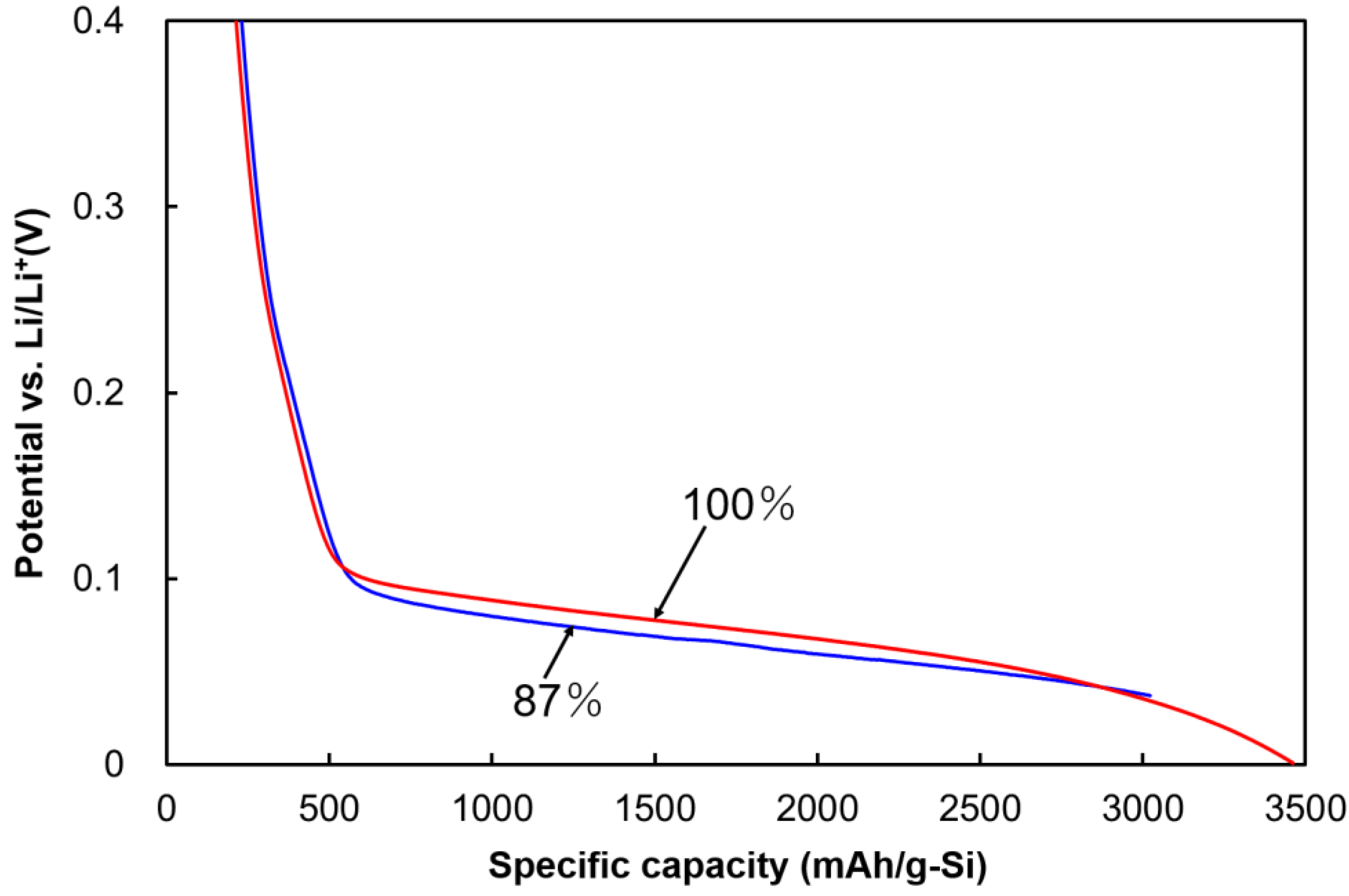
Figure 1. Potential variations of the Si anodes during the prelithiation processes of the 100% and 87% prelithiation cells.
Batteries 08 00049 g001
Figure 2. Variations in cell voltages and in cathode and anode potentials of the Si-based LICs during the rate test. (a) Cell voltage–specific capacity profile of the 100% prelithiation cell, (b) potential variations in the cathode and anode of the 100% prelithiation cell, (c) cell voltage–specific capacity profile of the 87% prelithiation cell, and (d) potential variations in the cathode and anode of the 87% prelithiation cell.
Batteries 08 00049 g002
Figure 3. Ragone plots of the 100% and 87% prelithiation cells based on rate test results.
Batteries 08 00049 g003
Figure 4. Impedance spectra (Nyquist plots) of the 100% and 87% prelithiation cells after the rate test and the proposed equivalent circuit of the cells.
Batteries 08 00049 g004
Figure 5. Variations in cell voltages and in cathode and anode potentials of the Si-based LICs during the cycle test at a constant current density of 1.0 mA/cm2. (a) Cell voltage–specific capacity profile of the 100% prelithiation cell, (b) potential variations in the cathode and anode of the 100% prelithiation cell, (c) cell voltage–specific capacity profile of the 87% prelithiation cell, and (d) potential variations in the cathode and anode of the 87% prelithiation cell.
Batteries 08 00049 g005
Figure 6. Energy densities and energy density retention of the 100% and 87% prelithiation cells during the cycle test at a constant current density of 1.0 mA/cm2.
Batteries 08 00049 g006
Figure 7. Fundamental Li-ion insertion and extraction properties of the Si anode in the half-cell configuration. (a) Potential–specific capacity profile and (b) irreversible specific capacity and Coulombic efficiency of the Si anode during Li-ion insertion/extraction cycles at different current densities.
Batteries 08 00049 g007
Table 1. Mass loadings, surface areas, and bulk densities of active materials for cathodes (AC) and anodes (Si) coated on current collectors (φ15 mm) and cathode-to-anode mass ratios for LIC cells.
CellActive MaterialCathode-to-Anode Mass Ratio
Mass Loading 1 (mg)Surface Area 2 (m2)Bulk Density 3 (g/cm3)
CathodeAnodeCathodeAnodeCathodeAnode
100% Prelithiation Cell3.950.9912.0 × 1034.950.280.933.99
87% Prelithiation Cell4.001.0412.2 × 1035.200.250.843.85
1 The masses of the conductive agents and binders used in the electrodes were excluded. 2 Surface area was calculated by multiplying the mass loading by the specific surface area. 3 Bulk density was based on the mass loading, electrode area, and coating thickness.
Table 2. Rate test sequence for performance evaluation of three-electrode LIC cells.
Current Density (mA/cm2)Number of CyclesCycle Selected for Performance Evaluation
0.0532nd
0.153rd
0.253rd
0.5105th
1.0105th
2.02513th
5.05025th
1010050th
2010050th
5010050th
Publisher’s Note: MDPI stays neutral with regard to jurisdictional claims in published maps and institutional affiliations.