Review

Approaches to Combat the Polysulfide Shuttle Phenomenon in Li–S Battery Technology

Department of Chemistry, Illinois Institute of Technology, Chicago, IL 60616, USA
*
Author to whom correspondence should be addressed.
Batteries 2022, 8(5), 45; https://doi.org/10.3390/batteries8050045
Submission received: 9 April 2022 / Revised: 5 May 2022 / Accepted: 13 May 2022 / Published: 17 May 2022

Abstract

:
Lithium–sulfur battery (LSB) technology has tremendous prospects to substitute lithium-ion battery (LIB) technology due to its high energy density. However, the escaping of polysulfide intermediates (produced during the redox reaction process) from the cathode structure is the primary reason for rapid capacity fading. Suppressing the polysulfide shuttle (PSS) is a viable solution for this technology to move closer to commercialization and supersede the established LIB technology. In this review, we have analyzed the challenges faced by LSBs and outlined current methods and materials used to address these problems. We conclude that in order to further pioneer LSBs, it is necessary to address these essential features of the sulfur cathode: superior electrical conductivity to ensure faster redox reaction kinetics and high discharge capacity, high pore volume of the cathode host to maximize sulfur loading/utilization, and polar PSS-resistive materials to anchor and suppress the migration of polysulfides, which can be developed with the use of nanofabrication and combinations of the PSS-suppressive qualities of each component. With these factors addressed, our world will be able to forge ahead with the development of LSBs on a larger scale—for the efficiency of energy systems in technology advancement and potential benefits to outweigh the costs and performance decay.

1. Introduction

With the current state of progression to renewable energy options, electric vehicles have garnered much attention as an alternative to offset the environmental effects of gasoline-powered vehicles. The burning of fossil fuels causes long-term environmental problems due to the toxicity and flammability of gasoline, which, when burned, produces air pollutants and particulate matter, such as carbon monoxide and nitrogen oxides, which are harmful to human health. The usage of gasoline-powered vehicles has also contributed to record-high carbon dioxide emissions [1].
Electric vehicles offer systems that mitigate the emissions of pollutants from gas-powered vehicles. There are three types of electric vehicles: plug-in hybrid electric vehicles (PHEVs), hybrid electric vehicles (HEVs), and all-electric vehicles (EVs)—each with varying degrees of battery technology usage [2]. Battery technology in these systems is more beneficial and environmentally friendly. For example, EVs which do not use gasoline do not emit direct exhaust or emissions and are categorized as zero-emission vehicles. While PHEVs use gasoline to power internal combustion engines and produce tailpipe emissions, the efficiency they gain from using batteries to power the motor markedly reduces greenhouse gas emissions compared to gasoline-powered vehicles [3]. However, prominent disadvantages of EVs include their short driving range compared to conventional gasoline-powered vehicles. An EV can travel ~250 miles before being recharged, while a conventional gasoline-powered vehicle can travel easily >400 miles. The average car takes ~5 min to refuel, but it can take hours for an EV to recharge, thus creating an inefficiency with time. Additionally, the price of the energy storage systems is very high, comprising 30–50% of the cost of EVs [4]. This prompts a discussion of possibilities on the current standard energy storage systems used in EVs and improving the current technology to store more power for widespread, inexpensive, and efficient use.
Lithium-ion batteries (LIBs) are exclusively used in EVs due to their excellent “charge-to-weight” ratio, rechargeability, and modest energy density of 150–265 Wh/kg [5]. The general structure of a Li-ion cell consists of a cathode containing the active material that is connected to a current collector; an anode usually consisting of a conductive carbon material; a polyethylene or polypropylene microporous separator between the cathode and the anode to avoid contact between the electrically conducting electrodes and to reduce the risk of shorting, and an electrolyte that facilitates the movements of Li+ ions between the electrodes. The cell operates by intercalation and de-intercalating Li+ ions during discharge and charge cycles. Thus, this movement of Li+ ions between the cathode and the anode is commonly referred to as “the rocking chair”. During discharge, lithium metal at the anode is oxidized to Li+ and an electron. The former travels through the electrolyte while the latter moves to the cathode (most commonly, lithium cobalt oxide) through the external circuit, where the cathode active material forms an intercalated compound. During charging, the flow of Li+ ions and electrons is reversed, i.e., Li+ ions migrate back to the anode and are stored as metallic lithium intercalated between graphene layers [6].
LIBs have been a prime clean energy storage technology for the past two decades, powering the world’s laptops, phones, and other electronic devices. However, their theoretical specific capacity (175–300 mA h g−1) or the amount of energy they can store is meager. For example, the LIBs needed to power large aircraft to efficiently travel long distances would need to weigh thousands of kilograms, resulting in many technical issues. Additionally, LIBs require the use of rare-earth elements, such as cobalt, for the cathode; with the growing usage of LIBs, there could be a shortage of these required metals in the near future [7]. The pioneering of future technology as alternatives to these batteries focuses on multiple factors: low cost of materials, which is necessary to extend the technology to wide-scale usage; high energy density and capacity, which is essential to maintain suitable battery size; and high reversibility and cycle life, which ensures that the technology is efficient and vastly improved from the current technology.
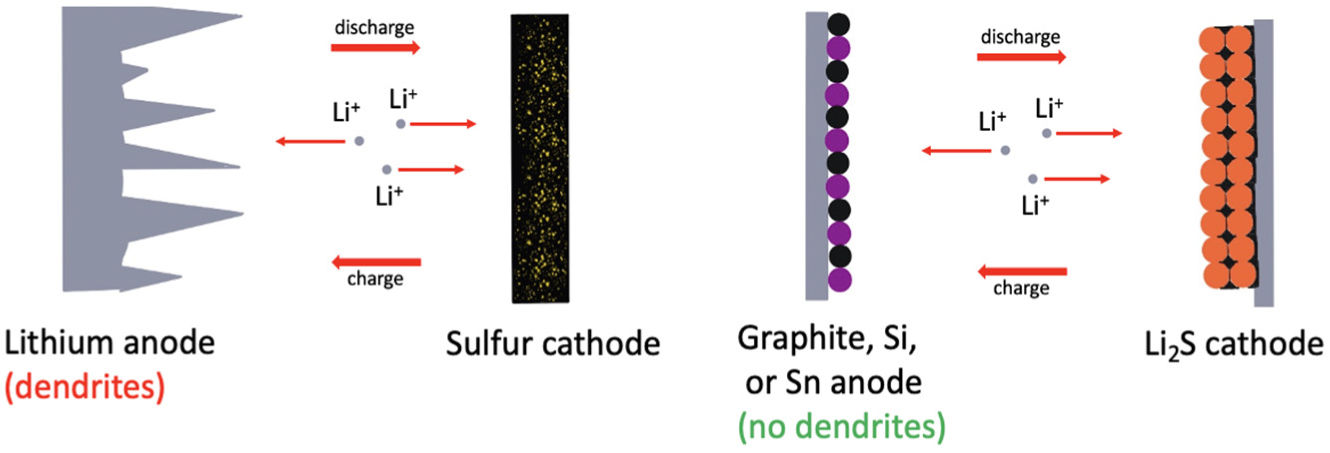
Lithium–sulfur batteries (LSBs) have been projected as a promising alternative due to their extraordinary theoretical specific capacity, more than four times that of LIBs and other transition metal oxide-based cathodes (1675 vs. 300 mA h g−1), and energy density (2600 vs. 265 Wh kg−1) [8,9,10,11]. They differ from LIBs because sulfur is used as the cathode material, which necessitates lithium metal as the anode, acting as the lithium source. Li–S cells function via redox reactions of metallic lithium at the anode and sulfur at the cathode. During a discharge cycle, sulfur is reduced to lithium sulfide (Li2S), and energy is released in a “conversion method”, which leads to the formation of a series of lithium polysulfide intermediates (Li2S8, Li2S6, Li2S4, etc.) [12]. Li2S is oxidized to elemental sulfur during charging, and lithium metal plating occurs at the anode, leading to the completion of energy storing (Figure 1). Another way that a Li–S cell differs from the traditional LIB is because it is obtained in the charged state (i.e., ready to give power). This allows Li–S cells to be stored and transported safely for long periods, as they remain stable during low discharge states [13].
Li–S chemistry involves an extra electron transfer (two electrons in LSBs, instead of one electron in LIBs). It allows for greater stored energy, conferring multiple of the aforementioned advantages of specific capacity and energy density [14]. With these high numbers, LSBs can store much more energy per unit volume, making them more advantageous than LIBs in this aspect. To address the environmental concerns of common metals used in LIBs, sulfur is abundant, cheap, and environmentally friendly, making it ideal for replacing the toxic and rare-earth metals, such as cobalt, found in most LIBs [15]. Despite such attractive advantages, the mass-scale production of LSBs has not yet occurred because of a few serious issues. The primary issue is that of the polysulfide shuttle when sulfur is reduced and goes through several stages of higher-order polysulfide intermediates, Li2Sn (4 ≤ n ≤ 8) [16]. Since they are relatively moderate in polarity, they dissolve in the electrolyte and create a parasitic “polysulfide shuttle” (PSS) effect. Due to a concentration gradient, they easily leach out from the cathode structure and reach the Li metal anode. This causes irreversible loss of active material as the long-chain polysulfides react with lithium metal through a disproportionation reaction. When these polysulfides migrate to the cathode during the discharge–charge cycles under an electric field force, they can quickly reduce to insoluble Li2S/Li2S2 particles, causing passivation and large polarization, which can lead to a severe slowing of both electron and ion movement [17].
The PSS also causes the growth of a thick solid-state electrolyte interface (SEI) layer on the anode with insoluble depositions of Li2S and Li2S2, rendering the battery inoperable after several cycles. This gives rise to high self-discharge rates and disruption of electrical conductivity and the transport of the Li+ ions. These issues result in poor Coulombic efficiency (defined as the ratio of the total charge extracted from the battery to the total charge injected into the battery over a complete cycle) and constant capacity fading [18]. This repeated deposition and dissolution of polysulfides also causes the non-uniform deposition of cathodic sulfur, resulting in increased impedance and polarization [19]. In addition, the dissolution of polysulfides increases the viscosity of the electrolyte, significantly reducing lithium-ion transport rates [20].
Another problem is the volume expansion of the cathode during the discharge process because of the much lower density of the discharge product, Li2S, compared to sulfur (dsulfur = 2.03 g cm−3 vs. dLi2S = 1.66 g cm−3). In the discharge process, the conversion of S to Li2S results in significant volume expansion (~80%) [21]. During cycling, the repeated change in volume expansion (during discharge) and contraction (during charge) will cause disintegration of the cathode structure, resulting in the loss of effective contact between the active material and current collector, leading to poor electrochemical performance and capacity decay [19,22]. Moreover, elemental sulfur and the discharge product Li2S are insulators and possess poor Li+ ion transport properties [8,9,10,11]. Thus, the cathode design calls for the nanofabrication of sulfur cathodes in an electrically conductive structure, such as mesoporous carbon [23].
Finally, uncontrolled growth of Li dendrites can also originate from the repeated stripping and plating of Li during cycling (Figure 2). Dendritic formations can pierce the separator and make their way to the cathode, resulting in a short circuit [19]. Additionally, volume changes due to stripping/plating cause cracks in the SEI layer, exposing new Li metal to the electrolyte, resulting in continuous decomposition of the electrolyte and rapid loss of both Li and electrolyte [21].
Therefore, to move forward with LSBs as a viable option for future energy storage improvement from the current state-of-the-art LIBs, addressing the issues associated with its redox reactions, especially that of the PSS phenomenon, is a must. The advantages that LSBs offer could greatly improve the price and availability of renewable energy sources and electric vehicles, offsetting the environmental and health effects of emissions from gas vehicles. To explore more into improvements on how to combat the polysulfide shuttle phenomenon in LSBs, recent advancements and trends in nanofabrication, shuttle-resistive materials, and electrolytes will be elaborated on in this review, as well as a discussion on future research from the current progress to date.

2. Principles of Li–S Cells

A standard Li–S cell comprises a metal lithium anode, an organic electrolyte, and a cathode made of a sulfur–carbon composite (Figure 1). The cell operation begins with discharge because sulfur is in the charged state. Li metal is oxidized at the negative electrode during discharge to produce Li+ ions and electrons. The Li+ ions move to the positive electrode through the electrolyte internally, while the electrons travel to the positive electrode through an external electrical circuit, thus generating an electrical current.
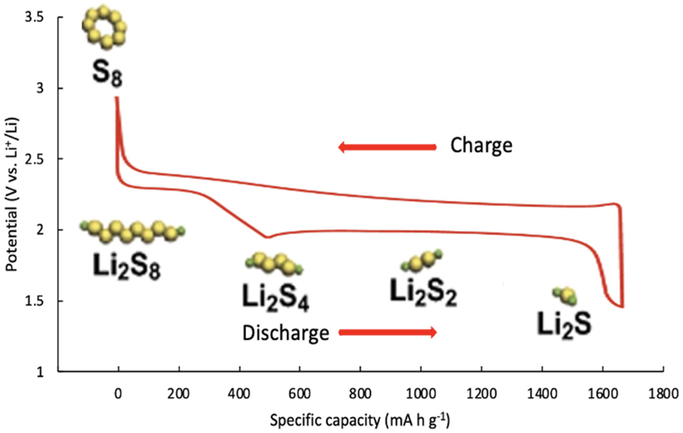
Sulfur atoms display a strong tendency towards catenation, which results in the formation of long homoatomic chains of various lengths. Octasulfur (cyclic S8 structure), which crystallizes at 25 °C as orthorhombic α-S8, has been characterized as the most stable allotrope at room temperature. During the discharge process, cyclo-S8 is reduced, resulting in linear higher-order lithium polysulfides, Li2Sx (6 < x ≤ 8). As the discharge process continues, lower-order lithium polysulfides, Li2Sx (2 < x ≤ 6), are formed by incorporating more lithium. Table 1 shows the products resulting from a discharge process in a Li–S cell [24]. During the charging process, Li2S is oxidized and converted back to S8 in reverse, along with the formation of intermediate lithium polysulfides transforming electric energy into chemical energy [24,25,26]. The overall reaction during discharge and charge at the cathode is:
S8 + 16Li+ + 16e ↔ 8Li2S     E = 2.20 V vs. Li+/Li
The overall reaction during discharge and charge at the anode is:
16Li ↔ 16Li+ + 16e
The discharge procedure goes through the following two stages:
(1)
Reduction reaction of elemental sulfur with Li forms long-chain lithium polysulfides, which possess high solubility in the ether-based liquid electrolytes.
S8 + 2Li+ + 2e → Li2S8
3Li2S8 + 2Li+ + 2e → 4Li2S6
Li2S8 + 2Li+ + 2e → 2Li2S4
(2)
Further reduction reaction between dissolved Li2S4 and lithium leads to insoluble Li2S2 and Li2S.
Li2S4 + 2Li+ + 2e → 2Li2S2
Li2S2 + 2Li+ + 2e → 2Li2S
A typical charge–discharge curve in a Li–S cell is represented in Figure 3. The discharge curves of the battery have two plateaus. The two discharge plateaus signify the conversions of S8 → Li2S4 and Li2S4 → Li2S, respectively. The first plateau at 2.4–2.1 V represents the transformation of elemental sulfur to soluble higher-order polysulfide ions. The second plateau occurs at 2.1–1.5 V, corresponding to the transformation of high-valence-state polysulfide ions to low-valence-state polysulfide ions, Li2S2 and Li2S. The charge curve usually has only one plateau at 2.25–2.3 V [27].
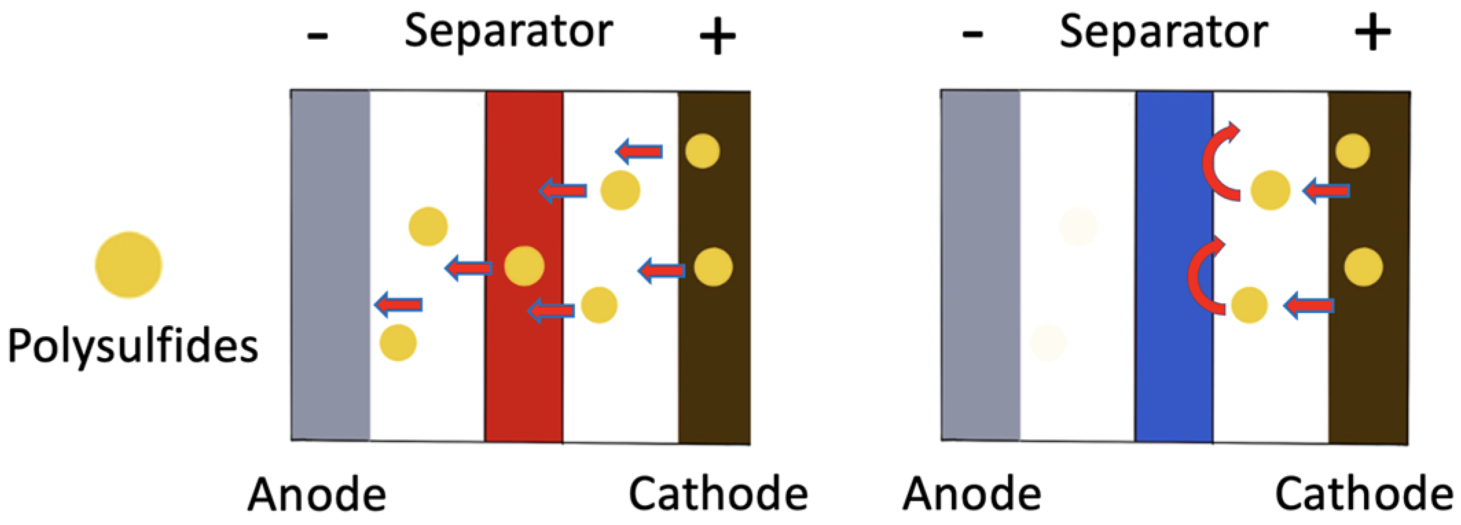
As mentioned earlier, the higher-order lithium polysulfide intermediates, Li2Sx (6 < x ≤ 8), are highly soluble in standard ether-based electrolytes. Consequently, they can easily shuttle between the cathode and anode, as illustrated in Figure 4. This phenomenon is widely referred to as the aforementioned “polysulfide shuttle effect”, which is primarily responsible for capacity fading [27].
As the soluble polysulfide ions shuttle to the lithium anode, they react to form irreversible and insoluble Li2S on the anode surface, resulting in both pulverizations of the SEI layer and gradual depletion of sulfur (Figure 5), leading to significant capacity fading of LSBs [26,27]. Another primary reason for capacity fading is due to the thick deposition of insoluble and nonconductive Li2S2 and Li2S on the cathode surface during every discharge cycle and incomplete oxidation of solid Li2S2/Li2S in the following charge cycle. This continuous shuttle effect and depletion of sulfur through the formation of unutilized Li2S2/Li2S increase electrical resistance and shorten the battery’s life [28].
Mikhaylik and Akridge developed a model to connect LSB charge–discharge efficiency, self-discharge, and discharge capacity quantitatively, proposing several mathematical equations. They came up with the charge and shuttle equation expressing the polysulfide dynamic by stating that the rate of reduction of high polysulfide intermediates on the Li anode surface is directly related to their concentration [29]. The shuttle mechanism of LSBs is dependent on the rate of reduction of high-order polysulfides at the Li anode surface, leading to Li2S. This reduction process is directly related to the polysulfide concentration and can be expressed with the following differential (Equation (6)) [27]. This shows that the rate of shuttling is proportional to the concentration of higher-order polysulfides multiplied by the shuttle reaction rate.
d[SH]/dt = I/qHks[SH]
  • [SH] = high PS concentration normalized to the cell surface or volume;
  • t = time;
  • I = charge or discharge current normalized to cell surface or volume;
  • qH = sulfur-specific capacity related to the high voltage plateau;
  • ks = heterogeneous reaction constant or shuttle constant.
The self-discharge of a Li–S cell is also problematic and a common phenomenon during no usage or resting. The main reason is due to the reaction between high-order polysulfide intermediates and the lithium metal anode [27]. For this reason, the open circuit voltage (OCV) is an important term in LSBs. OCV is used to analyze the changes in electronic energy in electrode materials and to estimate the state-of-charge (SOC) of the battery. The OCV is the electrical potential difference between the positive and negative terminals of a battery without a connected load, and it identifies the electrical potential capability of the battery [30]. It is important to note that the OCV of the Li–S battery also decreases with the increase in resting time, resulting in a permanent capacity decrease. The lithium polysulfide species are soluble in ether-based electrolytes, which function as “catholytes” after the discharge cycle (reduction of sulfur). These polysulfides slowly migrate toward the separator during the resting period due to the concentration gradient, and subsequently reach the Li-metal anode, where they undergo chemical reductions. Depending on the status of these reactions, the capacity decay may be either recoverable or irrecoverable. For example, if these reactions lead to insoluble Li2S2/Li2S mixtures due to reactions with the anode, both Li2S2 and Li2S precipitate out of the electrolyte and form a passivation layer on the Li metal surface, causing active material loss and poor cycle life [31].
This can be expressed with a mathematical equation to describe the correlation among the key parameters (the upper plateau capacity, resting time, and shuttle constant), as depicted in Equation (7) [27]. This equation elucidates that the self-discharge behavior of a Li–S cell is closely related to the polysulfide shuttle effect. They are associated with both the dissolution of higher-order polysulfides and the loss of active materials [27]. The longer the storage time, the lower the first discharge capacity. As polysulfide species can slowly dissolve in the liquid electrolyte during resting, both self-discharge and capacity fading during resting are unavoidable [27].
dlnQupper/dtR = −ks
  • Qupper = the upper plateau capacity, which depends on the concentration of both higher-order polysulfides and the specific capacity;
  • tR = resting time;
  • ks = heterogeneous reaction constant or shuttle constant.

2.1. The Cathode

Table 2 shows some of the current cathode materials used in rechargeable batteries. As can be seen, sulfur has the highest theoretical capacity due to its reduction reaction with Li+ to form Li2S. Sulfur is also the most cost-effective material among the available cathodes ($40/Ton for sulfur vs. ~$32,000/Ton for cobalt). Additionally, the abundance of sulfur in nature and its nontoxicity make it a very attractive cathode material [32].
Elemental sulfur is the critical component of the cathode in the form of S8, which determines the battery’s energy density (2600 Wh kg−1) upon reaction with lithium to form Li2S [33]. During the charge and discharge processes of a Li–S cell, several multi-step and the multi-electron redox reactions occur at the sulfur cathode, including the complex polysulfide phase transition process [19]. Although sulfur is a suitable cathode material, it insulates electrons and ions, making the cathode a poor conductor, causing high charge transfer resistance. As a result, sulfur requires hosting in a suitable conductive material to enhance the electrical conductivity of the cathode structure [24]. The electrical conductivity refers to how well a substance allows electricity to flow through it, thus playing a critical role in the electrochemical kinetics of the sulfur redox reaction by assisting the reversible redox of solution-phase polysulfides on the cathode surface and promoting the liquid–solid nucleation of Li2S [34].
The solution to high cathode resistance is to employ conductive carbon materials well dispersed with sulfur to provide superior electron transport between the electrical conductor, current collector, and the active material [9]. The most used conductive material to decrease the cathode structure resistance is the active carbon black, which possesses a high surface area and abundant micro- and mesopores [9]. The cathode conductivity increases, aided by forming a conductive carbon network and close contact between the conductive framework and the insulating sulfur/Li2S. The porous carbon structure not only promotes the retention of polysulfide species but also enhances the charge and electrolyte transport in the composite cathode [9]. Porous carbon materials have been the subject of extensive research due to their light weight (density ~2.2 g cm−3), good electrical conductivity, and high surface area. Other carbon materials with different morphologies (viz., carbon nanotubes, hollow carbon spheres, and hollow carbon fibers) have been extensively investigated to physically confine the soluble lithium polysulfides formed during cycling in the cathode structure [35].
A popular method to prepare a cathode includes casting a slurry composed of active material particles, a conductive additive, a binder, and a solvent on an Al foil current collector. Then, the solvent in the slurry is evaporated to dry the cathode material. Cathode material particles are filled into the prepared cathode layers. Thus, both binder and conductive additives will be located in the spaces between the active material particles to provide electrical contact between the active material particles and the current collector. The electrolyte solution containing Li+ ions permeates through the spaces in the electrode film and contacts the surfaces of active materials [36].
Alternative cathode materials, such as organic compounds containing S-S bonds, can be used in Li–S cells in contrast to S8 or inorganic materials. A non-elemental sulfur cathode prevents the polysulfide shuttle due to its structure. Xu and coworkers proposed a linear sulfur-rich organic material as the sulfur cathode, using commercial tetramethylthiuram disulfide (TMTD). Its linear structure and sulfur content contributed to cycling stability and good storage capacity. The TMTD-S cathode material delivered a capacity as high as 1054 mA h g−1 and retained at 930 mA h g−1 even after 100 cycles (current density of 0.5 C) [37].

2.2. The Anode

The Li–S battery anode consists of metallic lithium, where electrons are produced, and oxidation occurs. The anode is an essential component of the Li–S battery system as the stability of the anode governs the long-term stability of Li–S batteries [9]. During the discharge process, Li metal is oxidized to produce Li-ions and electrons. The Li-ions then migrate to the cathode through the electrolyte, while the electrons move through an external circuit to produce an electrical current [38]. Lithium possesses a very low density (0.59 g cm−3), high specific capacity (3860 m Ah g−1), and has been studied for the past five decades [33,39]. This alkali metal is the lightest of the solid elements, with considerable electrochemical potential. Lithium metal is highly reactive, and readily loses the outer shell electron to form Li+ compounds, making it suitable to serve as the anode [40].
Metallic lithium is considered as the ultimate anode for Li-ion batteries due to its very high capacity and low potential, leading to superior energy density. Unfortunately, metallic lithium is very reactive with most organic electrolytes. Consequently, it suffers from several drawbacks, such as low lithium cycling efficiency, dendrite formation, and negatively affecting cycling stability. Furthermore, it poses a safety concern resulting from dendritic growth, bridging the electrodes, potentially causing a violent reaction [26]. The dendrite formation and low lithium cycling efficiency are caused by the vulnerability of the SEI layer on the metallic lithium anode surface [26]. The unstable SEI layer cannot handle the shape and volume changes of the lithium electrode during plating and removal of ions. The result is the formation of lithium dendrites due to non-uniform lithium deposition and dissolution [26].
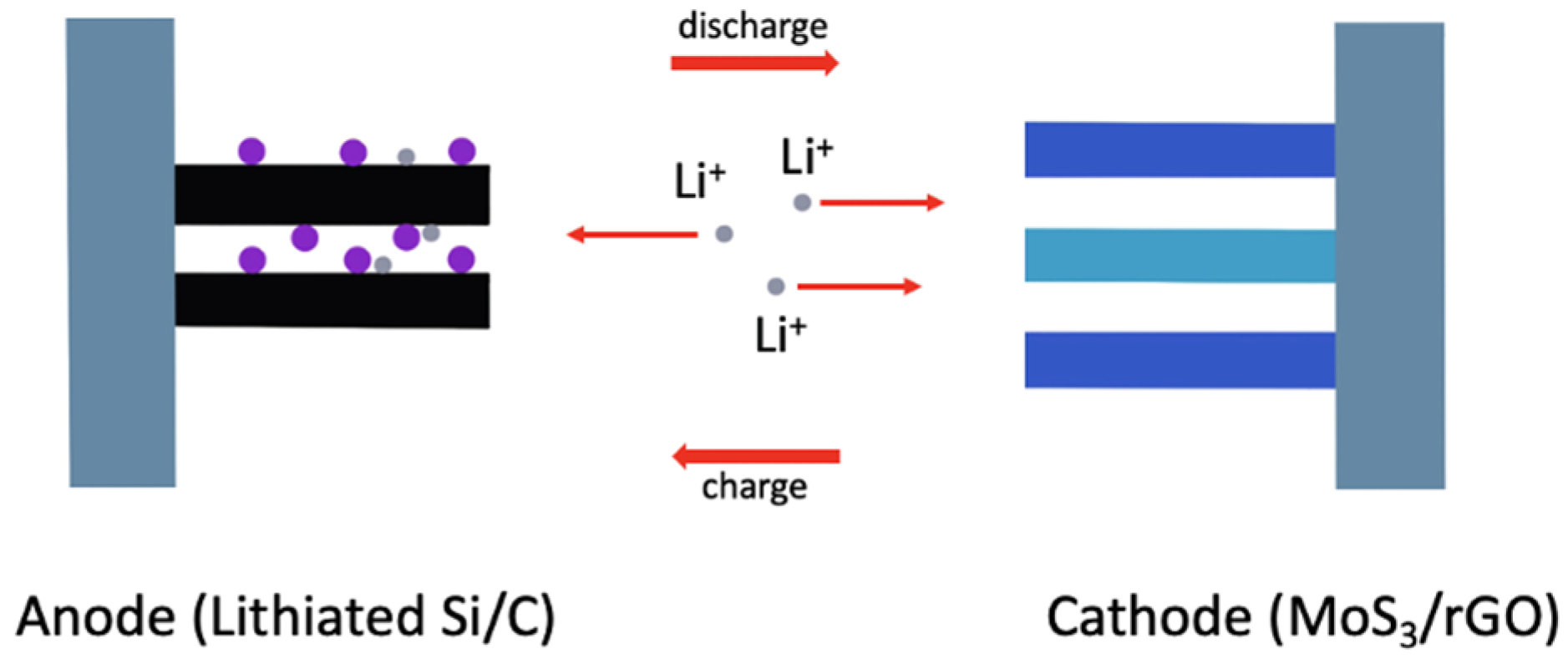
There have been several methods to improve the current status quo by preventing the negative effects that occur at the anode. Such methods rely on the protection of the lithium metal anode from undesirable side reactions and ensuring that the deposition is as even as possible to reduce the formation of the passivation layer. For example, one method has been a protective coating on the anodic surface, which would necessitate conductive, mechanically strong, and stable materials, such as carbon nanofibers or graphene sheets [14]. Another method that has been explored in this field is the use of an alternative anode, such as a silicon anode, which needs to be pre-lithiated.

2.3. The Separator

While the primary role of the separator is to prevent physical contact between the cathode and anode and facilitate Li+ transport in the cell, the separator directly affects both the safety and the cell performance. In other words, it serves to provide migration pathways for Li+ but prevents electrons from passing through to avoid a short circuit [41]. The most used separators are made from polyolefin polymers, such as polyethylene (PE) and polypropylene (PP), which possess melting transition temperatures between 135 °C and 165 °C, respectively [41,42]. The porous structures in these separators are created during the phase separation fabrication technique.
Polyethylene terephthalate (PET) and polyvinylidene fluoride (PVDF) are also used in separators but are less common [41]. A typical thickness of a separator ranges from 20–25 µm. This is very important because a thin separator can maximize the energy density of batteries by providing more space for the electrodes. On the other hand, a thin separator may increase the possibility of punctures, leading to short circuits. By contrast, if a separator is too thick, it may result in high resistance, poor cell performance, and low energy density [42]. The porosity of the separator is also very important as it allows for Li+ to pass through from the anode side to the cathode side and vice versa. The optimum separator pore diameter is ≤1 µm, having a porosity of ~40%. The pore size of the separator should only be large enough to absorb the electrolyte and enable Li+ to pass since a high porosity increases the possibility of punctures and reduces the mechanical strength of the separator [42]. The separator must have high wettability from the electrolyte to have low ionic resistance in the cell. By contrast, low wettability leads to non-uniform ion distribution, causing the growth of lithium dendrites and inefficient use of electrode materials [42].
Since the separator plays a crucial role in these kinetics, recent advances have sought to use modified separators, which can prove effective in trapping polysulfides and improving utilization rates (vide infra). He et al. demonstrated a carbon-modified separator, which is promising for its high electrical conductivity and ability to bind to polysulfides, which would be able to suppress the notorious PSS [15]. These modified separators can include materials, such as metal oxides, which can function dually with catalytic synergy for the redox reactions and act as a conductive factor to boost reaction kinetics [16]. For example, Chen et al. incorporated cobalt in N-doped carbon nanosheets on a polypropylene separator that enabled excellent conductivity while retaining over 98% Coulombic efficiency after 500 cycles, with an initial discharge capacity of 1344 mA h g−1; its Co-N-C and graphene layers were also able to effectively immobilize polysulfides via the availability of mesopores [17]. These PSS-resistant materials are very beneficial as coatings or additives on separators and will be elaborated on further when we discuss necessary components in addressing the issues associated with LSBs.

2.4. The Electrolyte

The electrolyte facilitates Li+ transport between the cathode and anode. While the carbonate-based electrolytes have been the gold standard for LIBs, they are not suitable for LSBs because of the reactivity of polysulfide anions with the carbonate group [43]. Polysulfide anions are highly reactive and participate in basic, nucleophilic, redox, and radical reactions [44]. Consequently, the most suitable solvents (Table 3) for Li–S cells have been limited to linear and cyclic ethers, such as 1,3-dioxolane (DOL) and dimethyl ether (DME). DOL forms easily a stable SEI layer on the lithium metal surface while providing lower polysulfide solubility and slower polysulfide reaction kinetics [44]. On the other hand, DME offers faster reaction kinetics and higher polysulfide solubility while being more reactive with the Li metal. The ideal solvent should be chemically stable against PS species and the Li anode, and it should offer high PS solubility and have a low viscosity [44]. Currently, 1M LiTFSI in 1:1 DME/DOL is considered the standard electrolyte for testing LSBs. The ionic conductivity of the ether-based electrolytes is ideally in the range of 10 to 12 mS cm−1 [42].
The chemical compatibility with PS is the highest priority for selecting a lithium salt for the electrolyte. Lithium bis(trifluoromethanesulfonyl)imide [Li(CF3SO2)2N], LiTFSI, a low-lattice-energy salt, has been reported to be one of the most suitable salts for LSBs. Lithium nitrate (LiNO3) salt is also used, but as an additive to the electrolyte. This additive is believed to react with the metallic lithium anode and forms a smooth and dense SEI protective layer on the Li anode surface. Thus, this SEI layer greatly helps the lithium metal anode not to react with lithium polysulfide intermediates, leading to superior cell cycling properties [45]. An electrolyte system containing LiTFSI and DME: DOL (1:1 by volume), and a small weight percent (~2 wt.%) of LiNO3, comprises one of the most popular electrolytes for Li–S cells (Figure 6) [46].

3. Requirements for Fabricating Superior Li–S Cells

As mentioned earlier, the successful commercialization of Li–S batteries depends on four major problem areas: (1) the PSS effect, (2) the poor conductivity of sulfur, (3) the volume management of sulfur during lithiation and delithiation, and (4) the dendritic growth of the Li metal anode [8,9,10,11,19]. Material selection and cell design need to address these issues by retaining polysulfides, increasing conductivity, accommodating the expansion of sulfur, and controlling dendritic growth. The right choice of materials will enhance redox reactions and improve cyclability at high capacity. The requirements for a commercially viable Li–S cell can be separated into the following major categories.

3.1. Nanofabrication of Sulfur with a Carbon Host

In the past two decades, advancements made with LSBs have involved attempts to mitigate the issues associated with them outlined above, including the nanofabrication of electrodes and the addition of materials in the host and electrolyte [47]. This is critical because the insulating nature of sulfur leads to the lower utilization of active material and, therefore, low capacity and sluggish redox kinetics. Nanofabrication of electrodes has included the use of structures such as nanosheets, nanotubes, and microspheres, and methods such as coating and electrospinning have been shown to be advantageous in several ways [8,48]. For example, nanomaterials with a large surface-area-to-volume ratio can be used to fabricate the cathode, increasing the contact area and subsequently redox sites between the electrolyte and the electrode. Nanofabrication can also provide volume expansion, as the materials selected can offer great mechanical stability and flexibility, subsequently resisting the pulverization effect of sulfur expansion. Lastly, nanofabrication can allow for greater sulfur hosting, attracting and accumulating lithium polysulfides, increasing Coulombic efficiency, and reducing capacity fading [49].
Thus, nanofabrication is necessary to enhance the conductivity of the sulfur cathode composite; otherwise, the full potential of sulfur (i.e., high capacity) is hard to achieve. Generally, nanomaterials have a size of <100 nm, and their properties differ significantly from those at a larger scale due to the increased surface-area-to-volume ratio [50]. Reducing the size of the active particles from micrometer to nanometer scale lowers resistance due to the increased contact area between ionic species and decreased time for diffusion by a factor of 106 [51]. In the past few decades, various nanofabrication approaches have been considered to overcome the insulating properties of sulfur with carbon-based conductive materials [52]. These materials have tunable pore sizes depending on the desired outcomes, such as micro-, meso-, or macropores, with diameters of <2 nm, 2 nm to 50 nm, and >50 nm, respectively [53].
To date, carbon-based material is the most suitable host for sulfur, and it can be made highly porous so that efficient sulfur dispersion can be achieved, resulting in close electrical contact [54]. Additionally, carbon possesses much lower density (2.2 g/cc) compared to transition metal oxides, which range from 4.5 to 6.5 g/cc. Carbon matrixes are incredibly beneficial to the sulfur cathode for the following reasons: (1) conductivity enhancements—since sulfur and the discharged product, Li2S, are insulators, they must be combined with carbon to acquire good electron transfer pathways and reinforce electrical conductivity; (2) anchoring effects—sulfur must be embedded into carbon matrixes to immobilize itself to form the carbon/sulfur cathode; (3) blocking effects—long-chain polysulfides are prone to dissolve in the electrolyte and shuttle from the cathode to the anode. The carbon structure pore size can be properly designed to avoid polysulfide leaching by physically holding polysulfide intermediates and inhibiting their outward migration while allowing the in–out diffusion of Li+ ions. It can provide capturing effects to suppress polysulfides’ shuttle effects and obtain boosted performance [33,54,55].

3.1.1. Single Core–Shell Structure Carbon Hosts

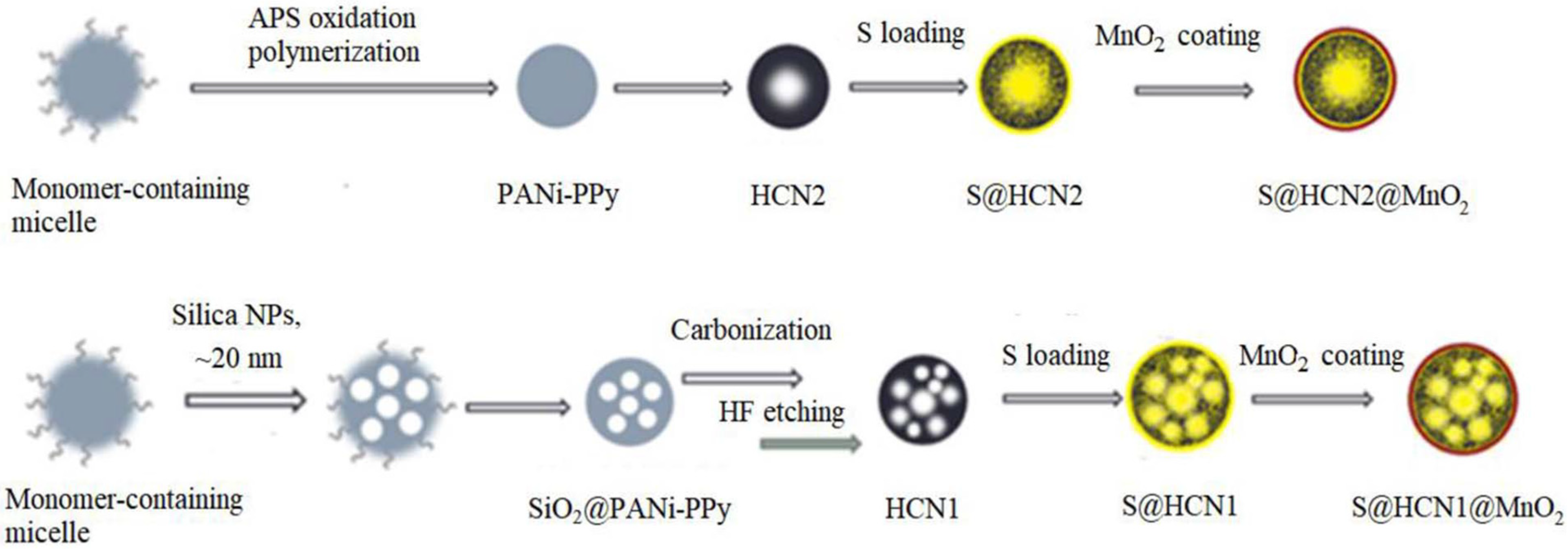
Our research group has developed a new cathode material, S@HCN@MnO2, in which MnO2 was coated over sulfur-filled hollow carbon nanospheres (HCNs) (Figure 7). The MnO2 layer was synthesized through the in-situ reduction of KMnO4. HCNs were derived from polyaniline–polypyrrole (PANi–PPy) nanoparticles as the precursor, prepared by the oxidative polymerization of the monomers in an aqueous solution in the presence of a surfactant, Triton X-100. To further increase the specific surface area (SSA) and pore volume of the cathode material, SiO2 nanoparticle impregnation was applied in the PANi–PPy precursor. The SiO2 was subsequently removed by HF etching after the carbonization step. The modified cathode, S@HCN1@MnO2, with increased porosity, displayed not only higher discharging capacity but also offered much improved redox kinetics (Figure 8) that enabled Li–S cells to run at a higher charging–discharging current density [56].
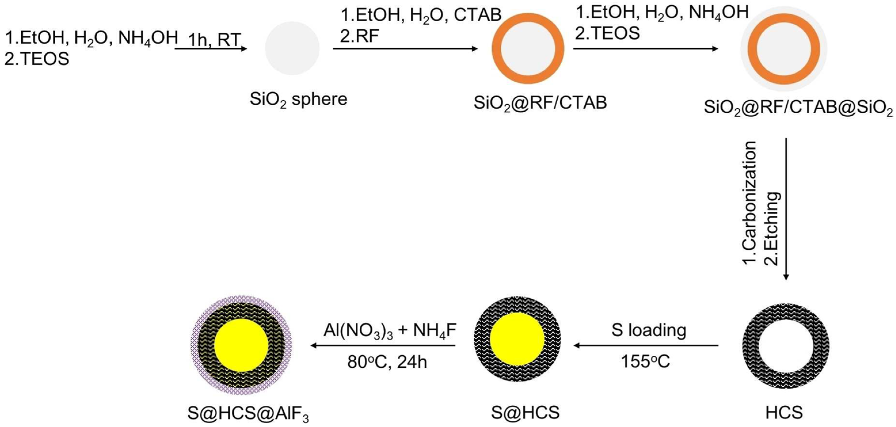
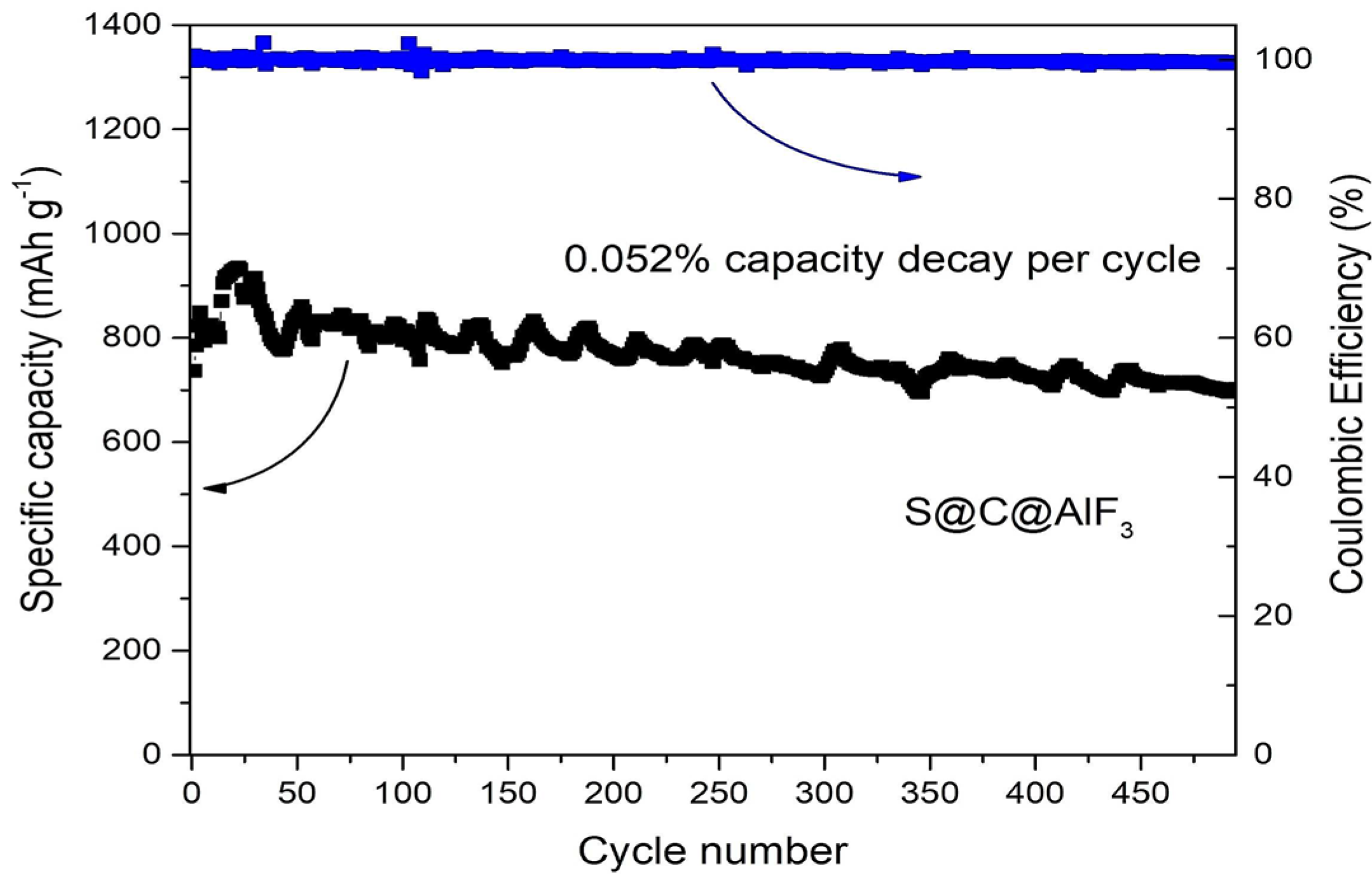
Our group has also developed a rational design of chemically entrapping polysulfides in a double-shelled sulfur cathode nanocomposite material (Figure 9). We developed a S@HCS@AlF3 hybrid nanocomposite composed of an inner conductive carbon layer and an outer AlF3 shell with strong chemisorption ability toward polysulfides [8]. This ultra-thin AlF3 coating was formed through a facile chemical precipitation method. The inner carbon layer was in close contact with poorly electrically conductive sulfur, while the outer ultra-thin polar AlF3 layer enhanced the overall electrical conductivity of the cathode structure. The mesoporous structure of carbon accommodated the volume changes of sulfur during charge–discharge and created a physical barrier to polysulfides leaking from the cathode. The second shell possessed strong chemical interaction with polysulfides. Moreover, the outer shells entrapped sulfur and polysulfides inside the cathode through a physical barrier. Furthermore, the ultra-thin AlF3 layer increased the electrical conductivity of the cathode materials, leading to faster ion transfer [8]. Figure 10 shows that the AlF3-coated cathode delivers a specific capacity of 934 mA h g−1 in the 22nd cycle, with a reversible capacity of 702 mA h g−1 after 500 cycles at 1 C, with only 0.052% capacity decay per cycle [8].
To address the volumetric change of sulfur during the discharge process, Cui et al. designed a sulfur–TiO2 yolk–shell nano-architecture (Figure 11). They were able to confine lithium polysulfides within the shell via an internal void space (created by partial dissolution of sulfur using a solvent mixture composed of isopropanol and toluene) and enhance active material utilization during electrochemical reactions. S42− was likely trapped at oxygen-deficient sites and coordinated with two Ti3+ sites via physicochemical interactions, restraining the dissolution of polysulfides. Compared with pure sulfur, the yolk–shell displayed stable cycling performance, with only a 0.033% capacity decay per cycle after 1000 cycles [57].
Li and coworkers developed a sulfur cathode material with a core–shell structure via precipitation, consisting of sulfur nanospheres in the inner layer and ultra-thin δ-MnO2 nanosheets in the shell, as shown in Figure 12. The sulfur nanospheres were dispersed in a solution containing polyvinylpyrrolidone (PVP), and then a KMnO4 solution was added to prepare the nanocomposite material with a high sulfur mass ratio of 82 wt.%. The MnO2 shell could be used as a catalyst to promote polysulfide adsorption and convert both S and Li2S during charging and discharging. The shell was also able to compensate for long-term sulfur expansion. The composite electrode showed a high specific capacity of 846 m Ah g−1 at 1 C and good cycling performance. The areal capacity of the electrode was recorded at 5.2 mA h cm−2 after 50 cycles, at a current density of 0.1 mA cm−2 [58].
Wu and coworkers synthesized a core–shell-structured sulfur/polythiophene (PTh) composite as the cathode for LSBs. It significantly enhanced the electrochemical performance of the cell and its cycle life. A coating was made using a chloroform solution and iron chloride as an oxidant, along with polythiophene. Sulfur particles were uniformly coated on the surface via in-situ chemical oxidative polymerization. A schematic illustration of the synthesis route is shown in Figure 13. The polythiophene layer covered the entire sulfur particle surface and worked as a conductive additive and a porous adsorbent, preventing the loss of the active sulfur material in the core. It effectively inhibited overcharging and the shuttle effects. A series of controlled experiments determined that 71.9% sulfur and 18.1% polythiophene were optimal compositions. The capacity of this composite was recorded at 830.2 mA h g−1 at 80 cycles at a current density of 100 mA g−1 [59].
Other groups, such as Sun et al., designed hollow core–shell interlinked carbon sphere (CSC) structures, changing the traditional hollow spheres and single core–shell structures (Figure 14). The reasoning behind this is that micropores have strong adsorption potential. Hence, their design for an optimal structure was to fabricate a microporous carbon core anchored to the mesoporous carbon shell to effectively trap dissolved polysulfides while facilitating a shorter distance of Li-ion transport, increasing electrical conductivity, and maximizing the loading of sulfur. These newly designed sulfur (CSC-S) cathodes demonstrated high discharge capacity and stable cycling, with 960 mA h g−1 after 200 cycles when run at 0.5 C. The CSC-S hybrid also showed excellent electrochemical stability and mechanical strength of the core–shell structure, indicating that the pulverization of the cathode seen during lithiation and delithiation was reduced [60]. Increasing the areal sulfur capacity and loading and doping with heteroatoms to improve conductivity in the future would continue building on this performance and possibly boost the initial discharge capacity [61].

3.1.2. Dual Core–Shell Structure Carbon Hosts

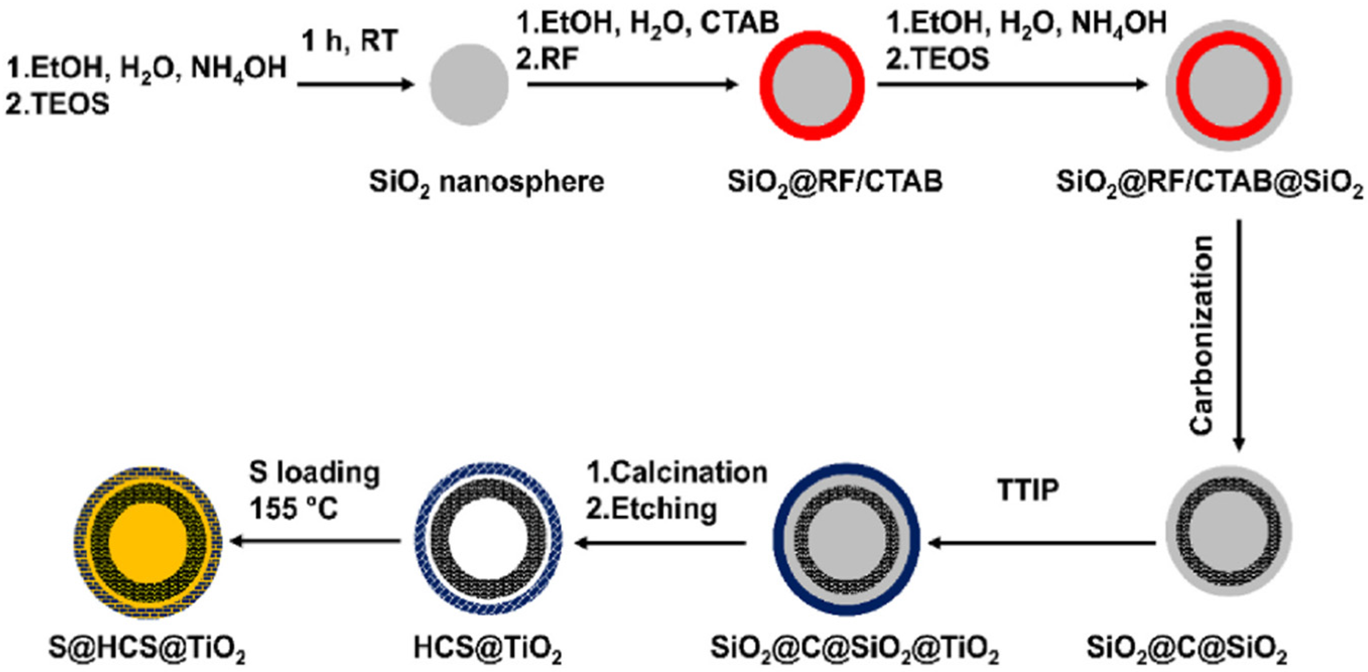
In another research work by our group, we have developed a new methodology for the synthesis of high-porosity hollow carbon spheres (HCSs) coated with TiO2 (S@HCS@TiO2) as the cathode host material to construct Li–S cells (Figure 15). The hollow structures of HCSs provided sufficient space for the volume increase of sulfur during lithiation. They functioned as a physical barrier to prevent the diffusion of lithium polysulfide intermediates out of the cathode structure. The polar TiO2 layer displayed strong chemical interaction with polysulfide species, leading to very good long-term cycling stability [10].
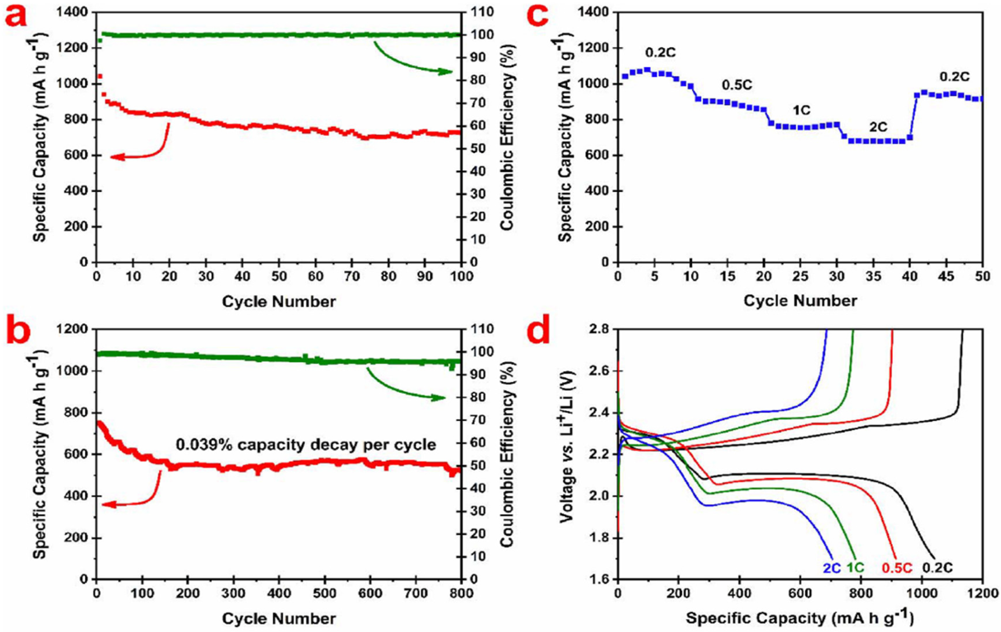
Figure 16 summarizes the electrochemical properties of the S@HCS@TiO2 cathode material. The sulfur content of this cathode material was estimated at 62 wt.% and all specific capacity calculations have been normalized to the sulfur content (1 C = 1675 mA g−1). The TiO2 coating layer’s contribution as the cathode material to the capacity was negligible. Figure 16a shows the discharge capacity and Coulombic efficiency of this nanocomposite cathode at 0.2 C for over 100 cycles. The initial discharge capacity was approximately 1050 mA h g−1, while, after 100 cycles, the capacity was decreased to 724 mA h g−1, which was approximately 70% of the initial capacity. The long-term cycling performance of the cathode was also obtained at 1 C for 800 cycles (Figure 16b). The cathode delivered an initial specific capacity of 751.6 mA h g−1 with a reversible capacity of 520.1 mA h g−1. This represents only a 0.039% capacity loss per cycle. The rate capability of this cathode at different rates (0.2 C, 0.5 C, 1 C, and 2 C, followed by switching back to 0.2 C) is depicted in Figure 16c [10].
Additionally, each cell was run for 10 cycles at a designated current density. This cathode delivered an initial specific capacity of 1042 mA h g−1 at 0.2 C, which is ~62% of its theoretical capacity. After the first few cycles, the cell was found to stabilize at around 1030 mA h g−1. When the current rate was increased from 0.5 C, 1 C, and 2 C, the specific discharge capacities were slightly decreased with the increase in current density. The delivered capacities remained as high as 915, 780, and 705 mA h g−1, as the current density was increased to 0.5, 1, and 2 C, respectively. When the C-rate switched to 0.2 C, it displayed a reversible capacity of 934 mA h g−1, indicating the high reversibility and robustness of this cathode material [10].
Figure 16d displays the charge–discharge profiles of this cathode at different C-rates. Only the first cycle profile at each C-rate was plotted to avoid confusion. At all rates, two associated plateaus around 2.0 and 2.3 V were observed, referring to the reduction reaction between Li+ and sulfur, which resulted in the formation of large and short-chain polysulfide intermediates [10].
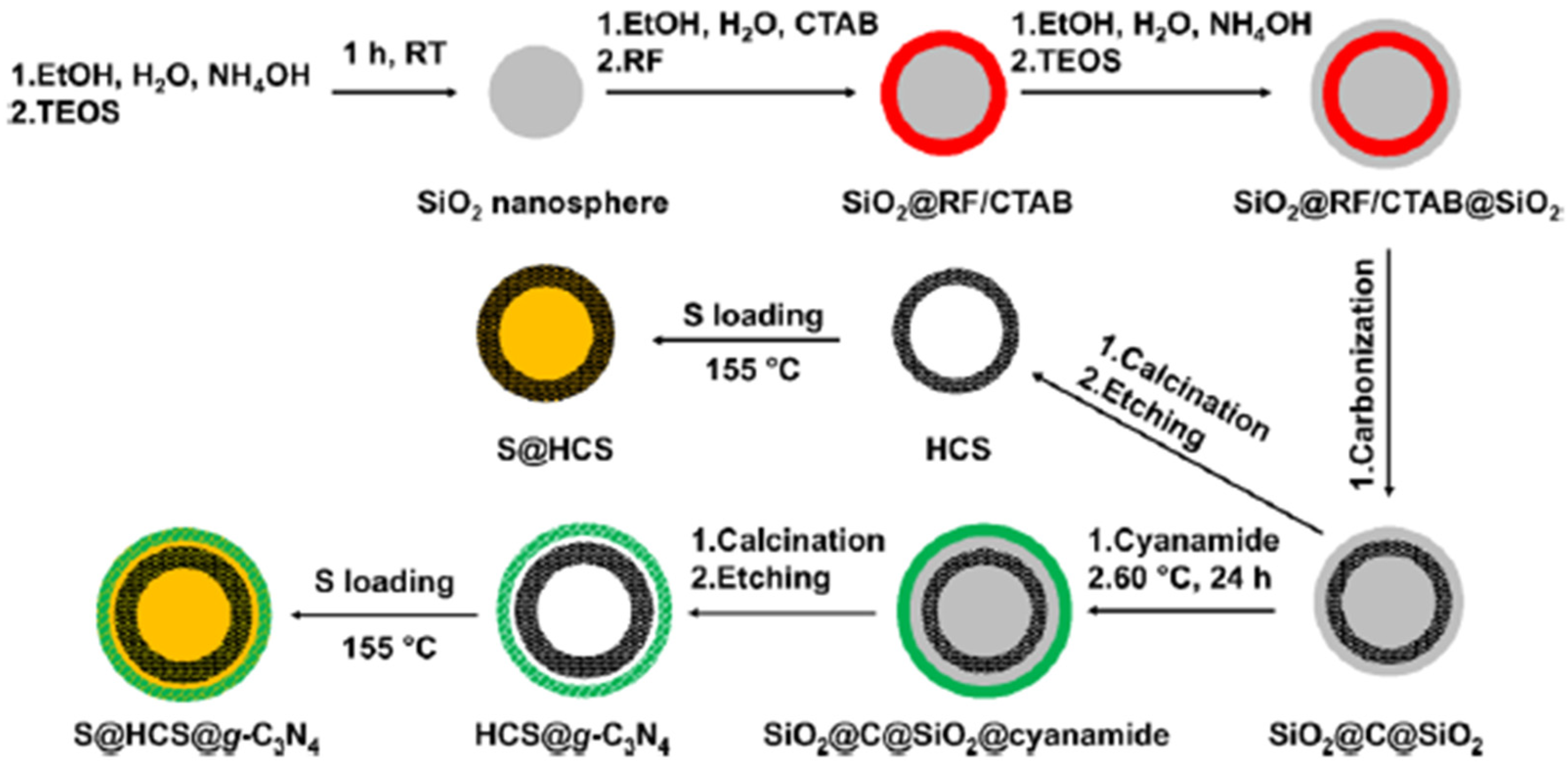
Furthermore, we have developed a novel sulfur cathode containing a dual core–shell structure to trap lithium polysulfide intermediates, S@HCS@g-C3N4 (Figure 17). The proposed hybrid structure was composed of an inner conductive carbon layer and an outer g-C3N4 shell. This design offered a double-layer mechanism to retain lithium polysulfides. The first protection came from the HCS structure. The cavity and mesopores in HCS accommodated the volume change of sulfur during discharge and created a physical barrier to lithium polysulfides escaping from the cathode structure. The second layer of protection came from g-C3N4, which trapped lithium polysulfides by strong chemisorption. The graphitic carbon nitride had a layered structure with high polarity, high nitrogen content, and strong adsorption behavior to polysulfides [11].
Figure 18a shows the cycling stability and Coulombic efficiency of the S@HCS@g-C3N4 nanocomposite cathode at the rate of 0.2 C for over 100 cycles. The cell delivered an excellent initial discharge capacity of 1420 mA h g−1. After 100 cycles, the discharge capacity was reduced to 885 mA h g−1, which corresponds to 62.4% capacity retention. However, at the same time, the Coulombic efficiency was more than 99%. After the first cycle, the discharge capacity markedly dropped to 1238 mA h g−1 in the second cycle. The capacity loss continued until the 10th cycle (1066 mA h g−1), after which the cell was stabilized, and the decay rate became significantly smaller [11]. Similar phenomena have been observed in many LSB studies. The rapid, irreversible capacity decay was because an SEI layer had not been entirely formed during the first few cycles. Furthermore, some sulfur particles had not been fully activated and participated in the lithiation/delithiation reaction, probably due to the sulfur spill-over or agglomeration. It is important to note that the capacity retention of the cell between 50 and 100 cycles was very high (~94%). This result indicated that there still exists a considerable loss of active material from the shuttling effect at early cycling (<50 cycles) due to un-infiltrated sulfur over the modified cathode structure. After approximately 50 cycles, the shuttle effect was minimal in the modified cathode structure. The charge–discharge profiles of selected cycles are plotted in Figure 18b. All curves exhibit one central plateau at charging and two significant plateaus corresponding to discharging processes. This finding was consistent with one prominent oxidation peak and two major reduction peaks observed in CV testing. It is worthwhile to mention that no plateau related to the reaction between Li and g-C3N4 was seen in the voltage range of 1.7–2.8 V [11].
The rate retention of S@HCS and S@HCS@ g-C3N4 electrodes was measured by cycling the coin cells through a gradual increase in current densities, 0.2 C, 0.5 C, 1 C, and 2 C, followed by switching back to 0.2 C (1 C = 1675 mA h g−1). Each cell was tested for 10 cycles at the designated current density. Each cycle’s corresponding specific discharging capacity was recorded (Figure 18b). The S@HCS@g-C3N4 nanocomposite cathode delivered a very high initial specific capacity of 1446 mA h g−1 at 0.2 C, ~85% of its theoretical capacity, while the baseline cathode (S@HCS) delivered that of 1305 mA h g−1 at 0.2 C. The high initial capacity of S@HCS@g-C3N4 is a direct advantage of the dual-shell design, which enhances sulfur utilization [11].
However, both electrodes’ specific capacities dropped dramatically after the first cycle to 1269 mA h g−1 and 1176 mA h g−1, respectively. The reason for this fast capacity decrease was due to the presence of un-infiltrated sulfur on the surface of both electrodes. After the first 10 cycles, the cells were stabilized to a great extent. However, with increasing current density, specific capacities gradually decreased due to slow redox reaction kinetics (poor Li+ diffusion through sulfur) and a lack of electron conduction. The specific capacities of the S@HCS@g-C3N4 cathode were recorded at 1446, 1023, 941, and 887 mA h g−1 at 0.2 C, 0.5 C, 1 C, and 2 C, respectively. When the current density returned to 0.2 C, the S@HCS@g-C3N4 cathode delivered a specific capacity of 1100 mA h g−1, which is almost the same value as the value after the 10th cycle at 0.2 C. This indicates the robustness of the S@HCS@g-C3N4 cathode after cycling at various rates. At a lower current density (0.2 C), the S@HCS@g-C3N4 cathode displayed good galvanostatic discharge–charge behavior [11].
Nonetheless, at higher current densities (>0.5 C), the redox reaction rate was limited, resulting in an increase in strong overpotential at 1.9 V. Finally, we investigated the long-term cycling performance of the S@HCS@g-C3N4 cathode at 1 C for 500 cycles. The S@HCS@g-C3N4 cathode delivered an initial specific capacity of 953 mA h g−1 and a capacity of 719 mA h g−1 after 500 cycles—a loss of only 0.049% capacity decay per cycle (Figure 18d) [11].
Zhang and coworkers designed and synthesized a carbon–sulfur nanocomposite by efficiently restricting sulfur in double-shelled hollow carbon spheres (Figure 19). The double-shelled hollow carbon spheres used SnO2 hollow spheres as the hard template. The carbon shell structure of the double-shelled hollow carbon spheres (DHCS) had several advantages compared with single-shelled hollow carbon spheres. DHCS were more effective in encapsulating the high content of active sulfur. DHCS enhanced the suppression of the outward diffusion of polysulfides from the carbon structures. Additionally, DHCS accommodated and alleviated the volume expansion of active materials upon prolonged cycling. This nanocomposite cathode showed cycling stability, with a reversible capacity of 690 mA h g−1 after 100 cycles at a constant current density of 0.1 C [61].
Wang and researchers have developed a dual core–shell-structured sulfur composite cathode material for LSBs by employing a simple one-pot method (Figure 20). Multi-walled carbon nanotubes (MWCNTs) and polypyrrole (PPy) were introduced into the sulfur composite to improve the conductivity, inhibit the diffusion of polysulfides out of the cathode structure, and relieve the volumetric expansion of sulfur during charge–discharge cycles. Sulfur particles were first deposited on the surface of MWCNTs, and then PPy was wrapped around the sulfur particles as an outer layer, making the dual core–shell structure. In this design, the inner MWCNTs acted as a conductive network for sulfur and an absorbent of polysulfides to some extent. At the same time, the outermost elastic PPy layer further enhanced the conductivity and stabilization of the dual-structure composite during cycling. Additionally, the PPy layer was able to restrain the polysulfides from moving out of the cathode structure and ease the volumetric expansion of sulfur. The resulting S@MWCNT@PPy composite displayed an initial discharge specific capacity of 1517 mA h g−1 and remained at 917 mA h g−1 after 60 cycles at a current density of 200 mA h g−1 [62].
Overall, dual core–shell structures are able to offer multiple functions of high conductivity and efficient suppression of polysulfide migration. There are pathways to be improved on with capacity retention after a more significant number of cycles. Nonetheless, the nonpolar carbon shell and polar shells used together create advantages over single core–shell structures.

3.1.3. Nanofiber/Nanorod Carbon Hosts

Our research group has also designed a host structure that combines a polar material with the conductive carbon to suppress the migration of lithium polysulfides. We synthesized MnO2-coated dual core–shell spindle-like nanorods, represented as S@HCNR@MnO2 (Figure 21). Manganese oxide can be easily prepared and is highly efficient in trapping polysulfides by converting thiosulfate to polythionate species [9]. The inner carbon layer is in close contact with sulfur and helps to improve electrical conductivity. The outer MnO2 layer serves as the protective layer against the polysulfide shuttling effect. The MnO2 layer also partially increases the overall conductivity of the nanorod structure [9].
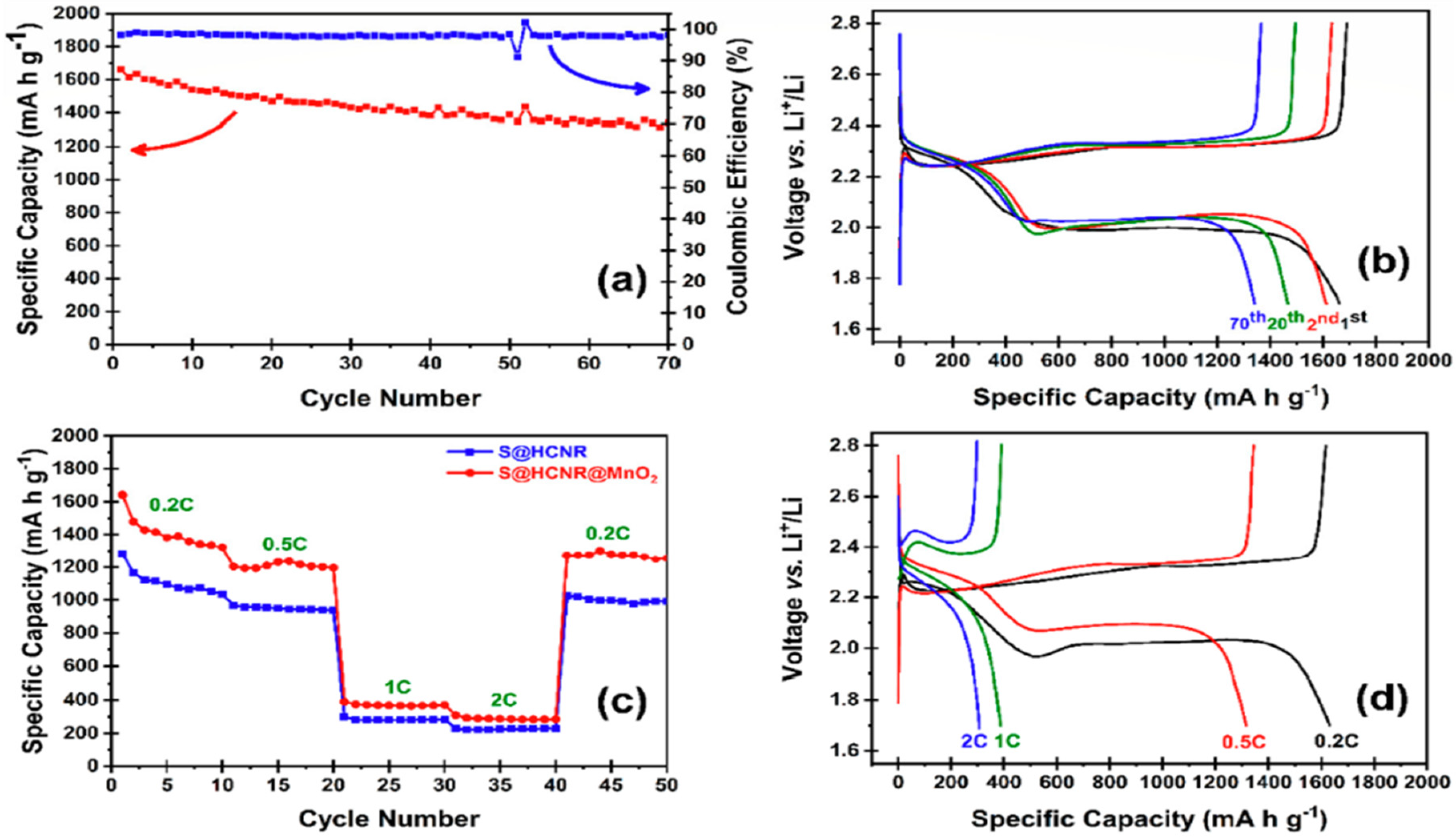
The electrochemical performance of both S@HCNR (without MnO2) and S@HCNR@MnO2 nanorods was investigated in a half-cell with a Li foil as the anode. The observed capacities were normalized based on the sulfur content of each sample. The S@HCNR sample contained approximately 70 wt.% of sulfur, while the S@HCNR@MnO2 nanorod sample contained 60 wt.% of sulfur with approximately 10 wt.% of MnO2. The charge–discharge behavior of the MnO2-coated electrode material was evaluated at a 0.2 C-rate (1 C = 1675 mA h g−1) in the voltage window of 1.7–2.8 V vs. Li+/Li (Figure 22a). This material delivered an excellent initial discharge capacity of 1661 mA h g−1. However, the capacity decayed to 1342 mA h g−1 with a Coulombic efficiency of 99% after 70 cycles. This result translates to ~80% capacity retention [9].
After the first cycle, the discharge capacity was reduced to 1500 mA h g−1, and then the cell stabilized with a slow decay rate. The galvanostatic discharge–charge profiles of the MnO2-coated electrode material for different cycles at 0.2 C are shown in Figure 22b. It is noteworthy that the voltage reached 2.3 V and then dropped to 2.2 V during the first charge. This hump is believed to be due to the MnO2 layer, which leads to the increase in charge resistance. The height of this hump decreased in successive cycles. Additionally, no plateau related to the reduction reaction of Li+ with the MnO2 shell was detected in the voltage window of 1.7–2.8 V. Consecutive cycling performance of both nanorod electrodes, S@HCNR and S@HCNR@MnO2, with a gradual increase in current density for every 10 cycles, is shown in Figure 22c. The rate was increased from 0.2 C to 2 C, followed by a recovery at 0.2 C. The S@HCNR@MnO2 electrode delivered an initial specific capacity of 1641 mA h g−1 at 0.2 C without any noticeable overpotential, which was ~98% of the theoretical specific capacity of sulfur. As the C-rate increased to 0.5 C, 1 C, and 2 C, the specific discharge capacity was gradually reduced to 1300 mA h g−1, 400 mA h g−1, and 320 mA h g−1, respectively (Figure 22d). When the current rate was switched back to 0.2 C, the discharge capacity was recovered at ~1350 mA h g−1, which is close to the delivered capacity recorded at 0.2 C in the first cycle. By contrast, the discharge capacity of the S@HCNR nanorod electrode decreased more significantly with the increase in charge–discharge rates. The specific capacity at the initial cycle was 1300 mA h g−1 at 0.2 C, but it reduced to 220 mA h g−1 at 2 C. This result demonstrates the excellent rate capability of the S@HCNR@MnO2 electrode [9].
He and his coworkers have prepared FeWO4 nanorods by employing a facile hydrothermal method to improve the electrochemical performance of Li–S batteries (Figure 23). The FeWO4 nanorods retained polysulfides and acted as an electrocatalyst in the LSB. The FeWO4 nanorods were able to adsorb lithium polysulfides and enhance the conduction of Li-ions, leading to inhibition of the PSS effect and enhancement of the electrochemical reaction kinetics for cycling stability and rate performance. The density functional theory calculations showed high binding energy between the FeWO4 nanorods and lithium polysulfides. The FeWO4 nanorods displayed an initial discharge capacity of 1318 mA h g−1 at a current of 0.8 mA, with a high Coulombic efficiency of 97%. They also delivered a capacity decay rate of 0.07% during 600 cycles at a current of 3.2 mA [63].
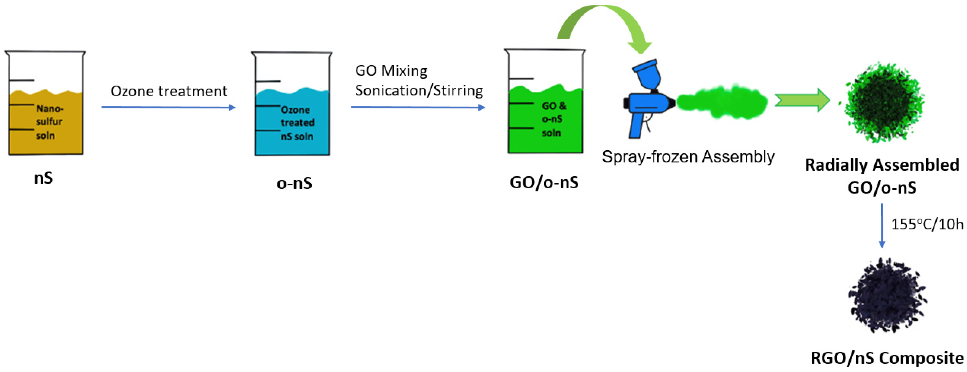
Yeon and coworkers have developed a rod-like nano-sulfur (nS) material and deposited it onto a radially oriented open-porous micro-spherical reduced graphene oxide (rGO) structure, for improving the rate and cycling capabilities of LSBs (Figure 24). The combined chemistry of a spray-frozen assembly and ozonation led to the formation of a radially oriented open-porous structure with a micro-spherical morphology, uniform distribution, and high loading of rod-like nS. The rGO/nS hybrid enhanced sulfur efficiency by redox kinetics and high rate capacities. The specific capacity and first-cycle Coulombic efficiencies were 1269.1 mA h g−1 and 98.5%, respectively. The results proved better than ice-templated, physically mixed rGO/nS hybrids or radially oriented open-porous rGO/bulk sulfur materials. At 4 C, the capacity resulted in 510.3 mA h g−1, with a capacity decay of only 0.08% per cycle for over 500 cycles [64].
Ni et al. have developed a new dual core–shell-structured nanocomposite, S@C@MnO2, as the sulfur host (Figure 25). It is composed of mesoporous hollow carbon spheres (MHCSs) with in-situ grown MnO2 on the surface. The highly conductive inner carbon is in close contact with sulfur, while the outer polar MnO2 layer was able to anchor polysulfides physically and chemically within the cathode structure. As MnO2 transitions to Mn3O4, it oxidizes polysulfides to intermediate polythionates species and additionally contributes to more efficient redox reactions. The S@MHCS@MnO2 cathode delivered a high specific capacity (1345 mA h g−1 at 0.1 C) and an excellent rate (465 mA h g−1 at 5.0 C), as well as a long cycling life of more than 1000 cycles with a decay rate of 0.052% per cycle at 3.0 C [65].
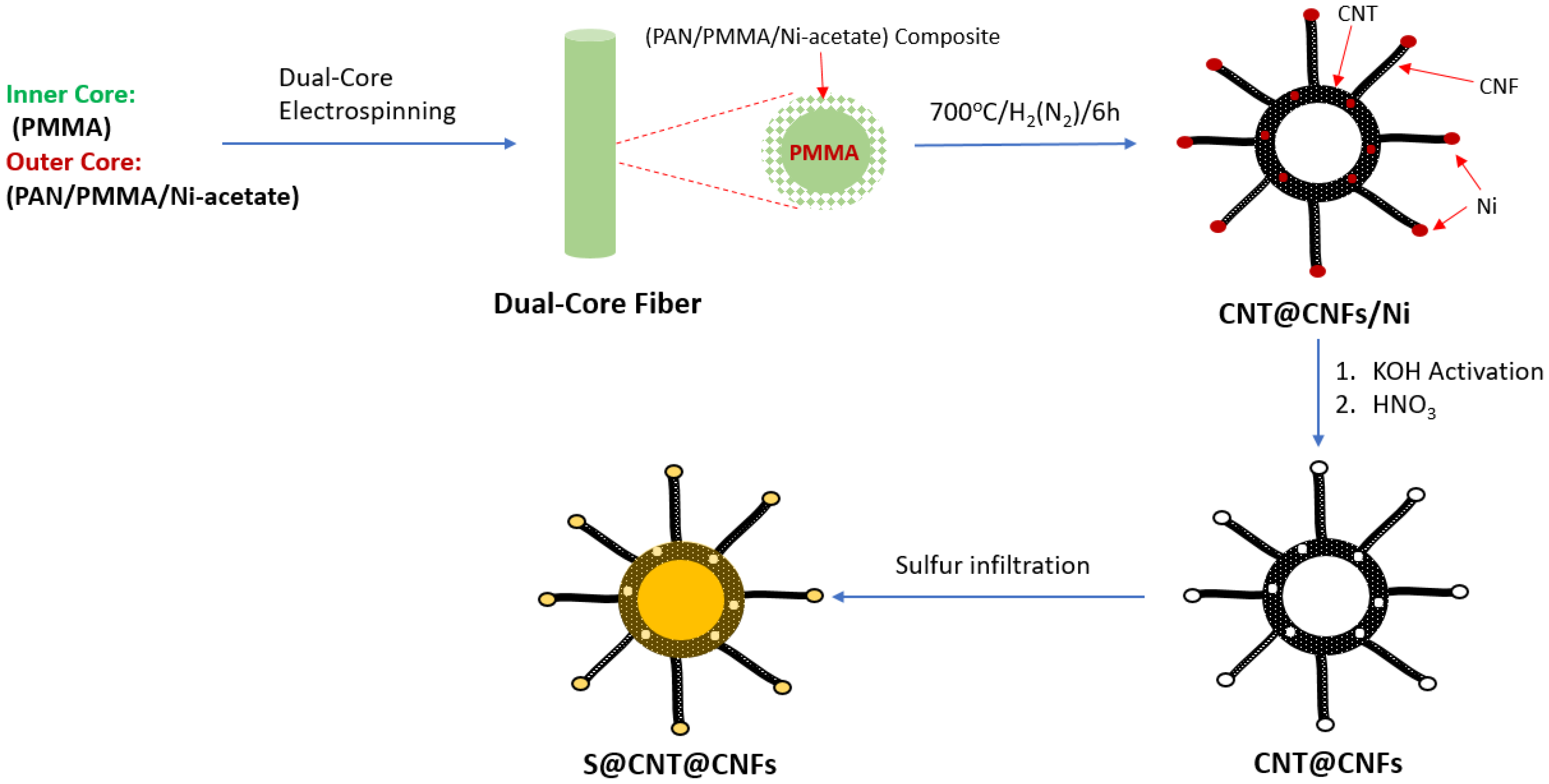
Another type of carbon host is carbon nanofibers (CNFs) with diameters of only a few nanometers; the microscopic structure and porous framework allow for higher conductivity, great mechanical flexibility, and a high degree of encapsulation and loading (Figure 26). The nanofiber design also allows for a high surface area and even the dispersion of nanoflakes and other multifunctional nanostructures, leading to high capacity and long-term stability [66].
These nanofibers can be synthesized through electrospinning, which employs organic polymers, such as polyacrylonitrile (PAN), and these are dissolved in a suitable solvent, such as N,N-dimethylforamide (DMF). This electrospinning process of producing porous carbon nanofibers (PCNFs), which Wang et al. prepared by using resole and triblock copolymer Pluronic F127, can prove complex; however, it can lead to desirable results [67]. Kang et al. attempted to simplify the electro-blown spinning technique with a PAN/polystyrene (PS) solution and thermal treatment, synthesizing a porous carbon nanofiber–sulfur cathode (S@PCNF), which used both a mesoporous and macroporous fiber structure (Figure 27). The smaller fibers were able to accommodate sulfur expansion up to 80% of the electrode weight, while the larger fibers served to trap polysulfides, and this composite demonstrated high initial discharge capacities of 954 mA h g−1 at 0.5 C and 602.2 mA h g−1 at 2 C [68]. With this easier method and improved cycling retention, this procedure could prove viable for future methods of fabricating nano-architectures while maintaining porosity and conductivity.
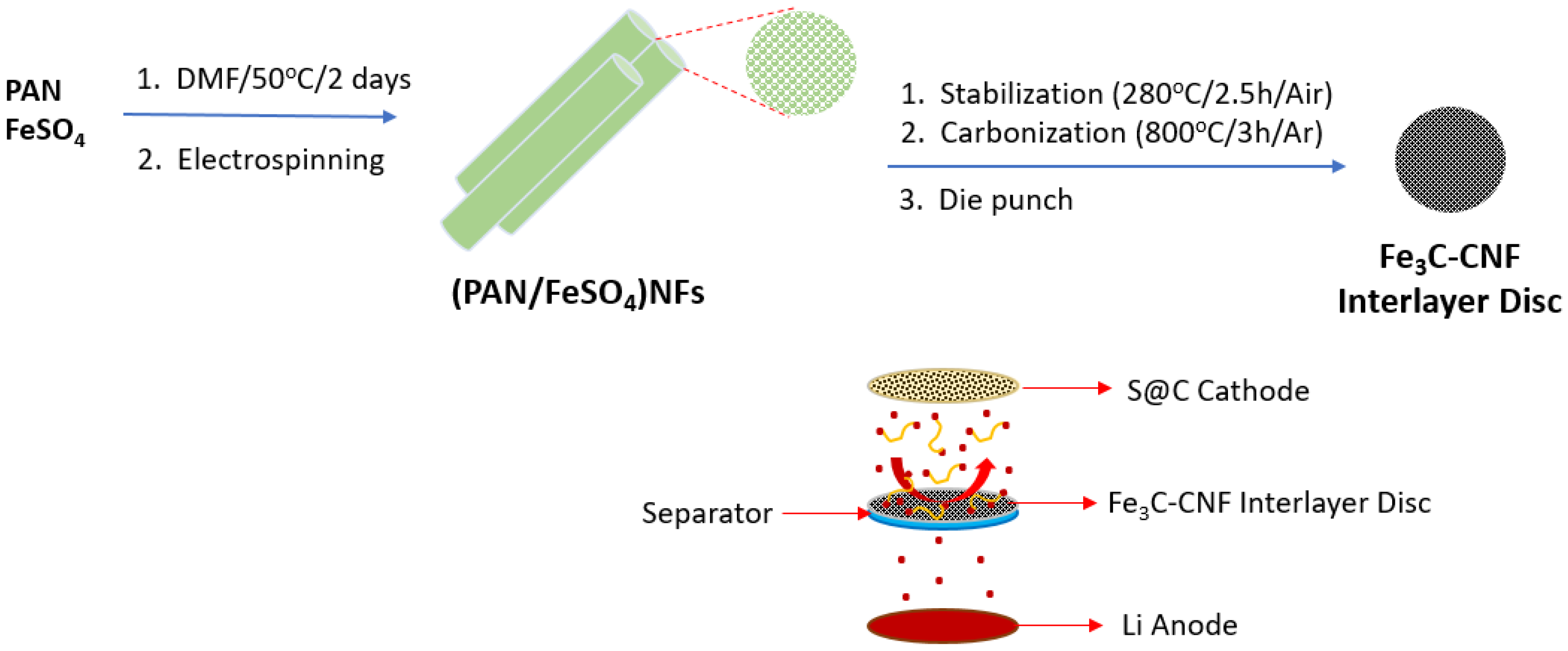
Additives can also help to suppress the PSS with the creation of inactivation areas, alleviating the loss of active material. CNFs are excellent for physically blocking the diffusion of polysulfides, but due to the nonpolar nature of carbon, this is unable to suppress it well chemically. For example, Zheng et al. reported an extremely high initial discharge capacity of 1560 mA h g−1 with CNFs designed on an anodic aluminum oxide (AAO) template and maintained a capacity of 730 mA h g−1 for 150 cycles [69]. CNFs may also be coupled with other strategies, such as carbon coatings on separators or the addition of conductive materials in order to boost conductivity and cycling life. For example, Wu et al. designed a multifunctional interlayer with Fe3C nanoparticles based on CNFs, promoting conductivity and electrochemical performance (Figure 28). The Fe3C interlayer exhibited strong chemical adsorption, allowing for a high reversible capacity of 941 mA h g−1 after 100 cycles at 0.2 C and low capacity decay of 0.091% per cycle after 250 cycles at 1 C [70]. This synergy of chemical and physical suppression would be helpful in suppressing polysulfide diffusion and increasing both rate capability and cycling performance.
As mentioned earlier, the modification of separators is another strategy that has been employed and explored in conjunction with CNFs. García-Soriano et al. used a modified separator with a porous sepiolite template and a glucose source for carbon. The separator and cathode were coated with a slurry synthesized from CNFs mixed with a 90% wt. ratio of PVDF in N-Methyl-2-pyrrolidone (NMP), which was then ball-milled and painted on the structures. With this layer of coating, the cathode exhibited greater cycling stability and increased capacity, which may be a direct result of the polysulfide suppression benefits that CNFs offer. In addition, X-ray photoelectron spectroscopy (XPS) showed that there was an increase in COSO2−/SO32− functional groups forming on the surface of the cathode structure, indicating greater interaction and anchoring of polysulfides as a result of the CNF coating. Excellent rate capability was demonstrated, suggesting that the CNF coating does not slow the transport of Li-ions even at high C-rates.
The study found an initial discharge capacity of 1234 mA h g−1 with the CNF-coated separator, a massive improvement from the capacity of the uncoated separator (171%), which displayed an initial discharge capacity of 720 mA h g−1 [71]. After 250 cycles, capacity retention was maintained at 60%, with a decay of 0.20% per cycle. This study is worth noting for the usage of low-cost and green materials, such as the abundant and environmentally friendly sepiolite, as well as the demonstration of high performance and conductivity achieved (demonstrated by 99% Coulombic efficiency and higher discharge capacities) through the usage of CNFs. This method is promising, with elaborations on future directions to possibly improve capacity retention and reduce capacity decay [72].
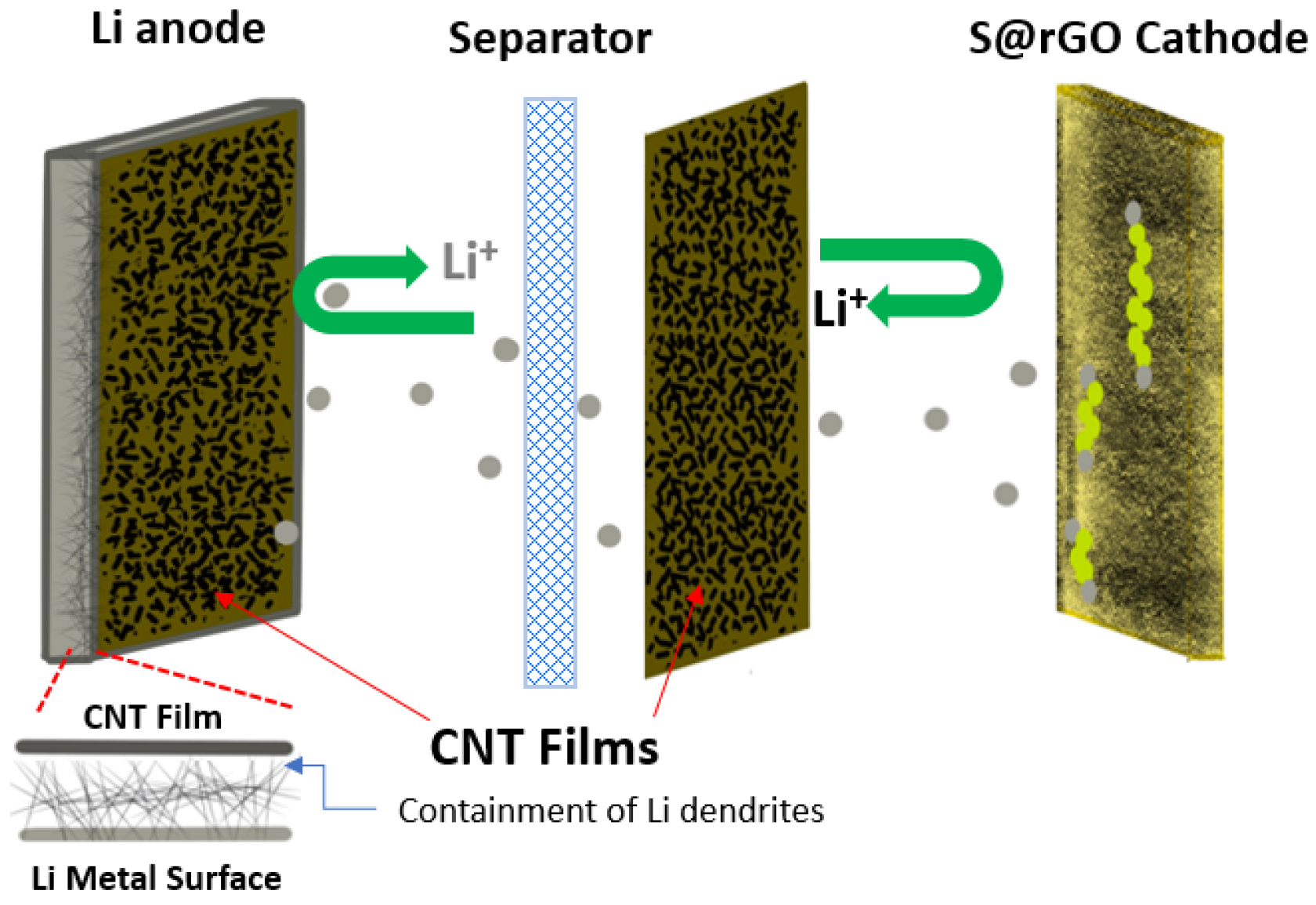
Nanorod carbon hosts have also been used, exhibiting high specific capacity and allowing unique hyperbranched hollow architectures. These rod and tube structures can take multiple forms, such as the ordinary carbon nanotubes (CNTs), which are produced in powder form and generate a core–shell structure that arises from the strong interaction of sulfur with the surface; which are bound by van der Waals forces and are mechanically stronger than ordinary CNTs; and CNT films (Figure 29), which are versatile and can act as both a suitable host and barrier on either side of the separator to protect the electrodes, as Xie et al. demonstrated and would be beneficial for both LSBs and other metal-based batteries [73]. The hollow quality of these carbon hosts is beneficial in offering extra space accommodation and can prove helpful in the confinement of polysulfides [74]. Chen et al. reported a hollow carbon nanorod structure with encapsulated sulfur from a sodium thiosulfate source (CNR-S) synthesized with a chemical vapor transport and condensation reaction (CVTC) with carbon coating over the MgO nanorods. This created a 3D hierarchical maze-like nanostructure in which sulfur was loaded via an in-situ precipitation method. Scanning Electron Microscopy (SEM) and Field Emission Scanning Electron Microscopy (FESEM) analysis show that the interlinked architecture effectively resists volume expansion and stress. In addition, Nyquist plots showed only slight charge transfer resistance, which is excellent in preserving the structure and viability of these electrodes. These CNR-S nanocomposites also delivered a high initial discharge capacity of 1378 mA h g−1 at 0.1 C and high capacity retention, demonstrating their stability during cycling [75].
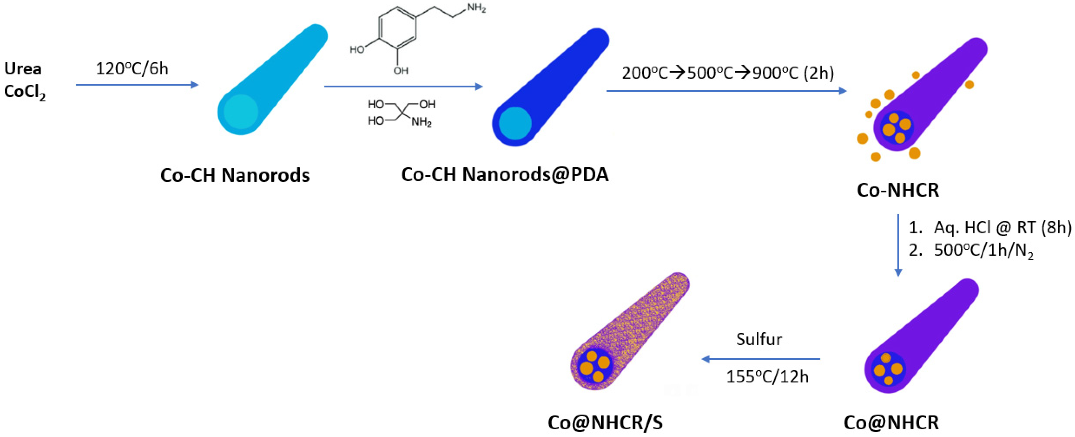
The fabrication of these nanorods can also employ methods that have been covered in this paper, such as nitrogen doping or polar additives. For example, Zhang et al. studied cobalt-embedded nitrogen-doped hollow carbon nanorods (Co@NHCRs) with density functional theory calculations for justification (Figure 30). They used polydopamine (PDA) as the source for N-doped carbon and cobalt carbonate hydroxide (Co-CH) nanorods derived from the hydrothermal method as the hard template. They showed that these additives greatly increased the ability to anchor Li2S and other polysulfide products, reducing the loss of active material and maintaining good electrical conductivity and interface contact [76]. In addition, these nanorods can be used in combination with other carbon structures, such as carbon nanotubes. Zou et al. prepared a free-standing interlayer formed by a combination of PVDF, CeF3 nanorods, and carbon nanotube film. This network structure and low weight are ideal for their high ability to adsorb polysulfides and be adapted for lightweight batteries and maximizing mass-specific capacity. CeF3 is also an excellent ion conductor and has great polysulfide adsorption ability, making it a good candidate as an interlayer material. This structure exhibited excellent electrochemical performance, with a high specific capacity of 1505 mA h g−1 at 0.05 C and an extremely low capacity decay of 0.063% per cycle. It also maintained a high discharge capacity for over 100 cycles at 0.2 C, demonstrating great cycle life and performance [77].
When used in synthesis with other methods, these carbon-based structures have the potential to mitigate the effects of the PSS and lead to high sulfur utilization and great electrochemical performance. Further studies may extend into the realm of optimizing cycling life and ease of preparation, but these strategies are promising and should be further explored in combination with other possible methods discussed in this review.

3.1.4. Carbon Cloth-Based Carbon Hosts

In contrast to activated carbon of other forms, carbon cloth (CC), which is synthesized from amorphous carbon fibers of varying diameters, offers the advantage of high electrical conductivity and high flexibility, which allows for ion transport channels and void space for the volume expansion of sulfur upon lithiation of the electrodes. CC can be fabricated into a binder-free and free-standing cathode. When activated, it has a high surface area and microporous structure, allowing for sufficient S loading and utilization of active material [78]. Most importantly, CC easily allows for the mass-scale fabrication of cathodes for LSBs since it is not nano-synthesized. The conversion of existing traditional nanoscale synthesis to cost-effective bulk-scale fabrication with high-throughput and scale-able methods is not only of great benefit but a requirement for industrial applications [79]. In addition, carbon cloth offers several advantages over other carbon forms, such as the ability for scale-up, flexibility, significantly higher surface area, and an interconnected three-dimensional porous architecture for the loading of active materials, allowing the sulfur to diffuse into the voids (≤2 nm) of the carbon fibers [26,79].
Many studies have sought to explore the potential of CC in usage with LSBs. Xu et al. found that the cycle life of LSBs was significantly stabilized with a highly loaded, binder-free sulfur cathode using an activated carbon-fiber cloth that had gone through chemisorption with a Co3O4 slurry (Figure 31). Charge and discharge profiles revealed that the carbon cloth cathode exhibited a higher initial discharge plateau than the pure CNF/S electrodes, and even after 300 cycles, the cycling performance and Coulombic efficiency remained excellent, indicating greater sulfur utilization and good reversibility. It was also noted that the addition of CC@Co3O4 rendered Li2S6 solutions light yellow for hours, while the standard carbon black solution did not have an effect. This suggests strong adsorption in the former case [80]. This can provide an explanation for the favorable results, as well as the synergic effects of the high surface area and conductivity of the CC-S matrix (as well as the Co3O4 nanocrystals favorably affecting redox reactions).
As previously mentioned, the addition of heteroatoms can help to increase the polarity of the nonpolar host and potentially increase conductivity and electrochemical performance. Tian et al. used CC doped with molybdenum to address the sulfur volume expansion problem and trap polysulfides using either the soaking or vapor flow method. These cathodes were prepared by growing MoS2 nanosheets on CCs with a hydrothermal method, followed by a two-step melt diffusion method (Figure 32). After 10 cycles, cyclic voltammetry (CV) scans showed good stability (superimposition of the peaks), and the Coulombic efficiency was significantly higher than in the control cells. SEM analysis indicated that the polar nanosheets allowed sulfur to infiltrate successfully and had a significant adsorption effect of inhibiting the PSS. After 300 cycles, it was also shown that the polysulfides were attached to the carbon fibers, showing that CC can be used as a good current collector [81]. The overall improvement in electrochemical catalyzation and Coulombic efficiency shows carbon cloth and polar nanosheets as promising and nontoxic current collectors.
While carbon hosts have emerged as a promising solution to the drawbacks of Li–S chemistry, they pose problems with capacity decay because carbon is nonpolar and cannot bind strongly to the polar polysulfides. As a result, polar materials, such as TiO2 and SiO2, have been examined for sulfur hosting; however, they have much lower electron and ionic conductivities, impeding ion/electron transport and lowering sulfur utilization and rate capability. Guo et al. grew a nano-wall array of Mn3O4 on carbon cloth; the rationalization was that Mn3O4 has better stability than MnO2 (Figure 33). The structure forms “nano-reservoirs” that can trap polysulfides, and the nano-array 3D framework provides rapid electron transport and allows for volume expansion [82]. However, capacity retention was only at 60% after 3000 cycles, and future works should focus on improving the capability and rate capability while possibly utilizing polar structures with CCs.
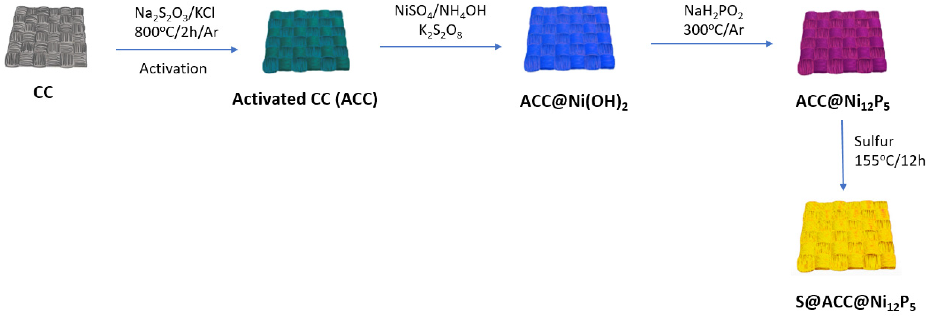
In an unpublished work, our group has utilized carbon cloth to serve as the sulfur host and coated it with Ni12P5 to make S@ACC@Ni12P5 (Figure 34). Ni12P5, a transition metal phosphide (TMP), is considered one of the most valuable electrode materials in the field of electrocatalysis [83]. Ni12P5 can trap soluble polysulfides through polar interaction and effectively catalyze the decomposition of Li2S to improve the utilization of active materials [83,84]. Furthermore, Ni12P5 is highly conductive due to its zero band-gap energy, allowing for the effective transmission of electrons and Li-ions, amplifying rate performance, and reversible capacity [85].
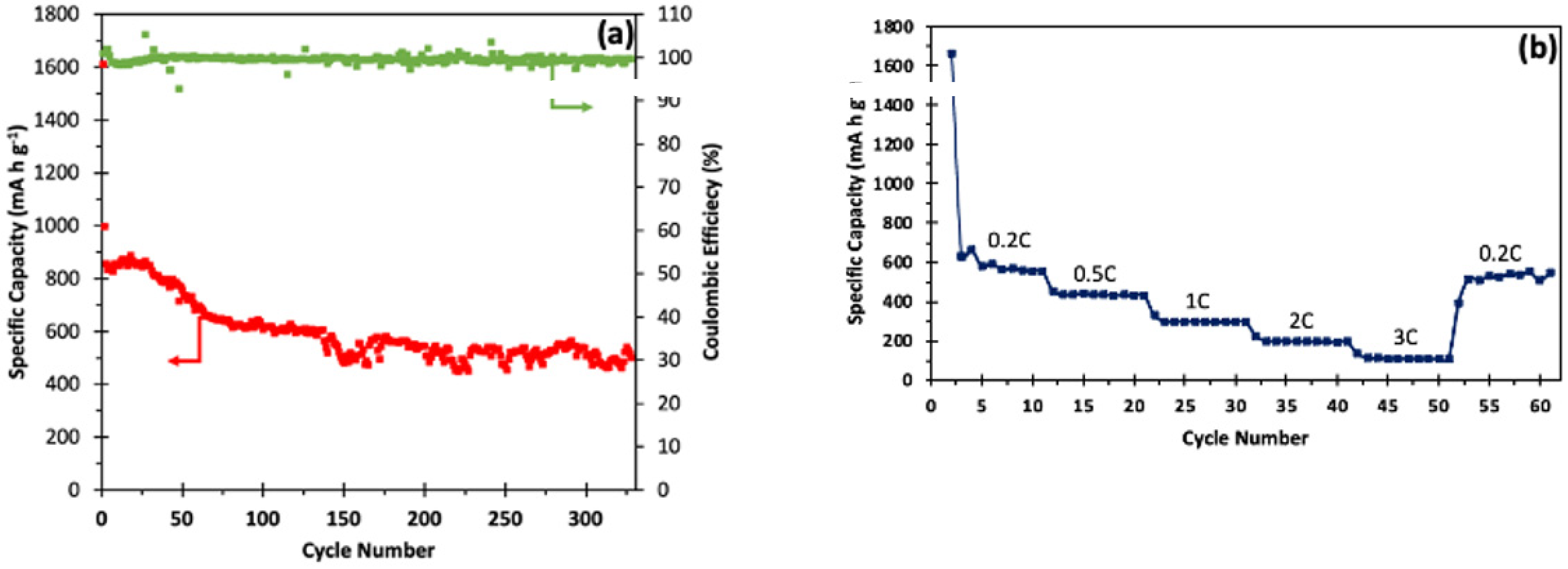
Cells made with our sulfur host material had impressive results, reaching theoretical capacity (>1600 mA h g−1) during initial cycling and maintaining 455 mA h g−1 for >400 cycles at 0.2 C. Figure 35a summarizes the electrochemical testing of the S@ACC@Ni12P5 carbon cloth electrode material. The sulfur content of the cathode material was estimated to be 70 wt.%, and all specific capacities have been normalized with the sulfur content (1 C = 1675 mA h g−1). It shows the discharge capacity and Coulombic efficiency of the S@ACC@Ni12P5 carbon cloth at 0.2 C for over 350 cycles. The initial discharge capacity was approximately 1610 mA h g−1, while after 100 cycles, the capacity decreased to 650 mA h g−1 and finished at ~515 mA h g−1, maintaining approximately 80% of capacity. The rate capability of the S@ACC@Ni12P5 carbon cloth at different rates, ranging from 0.2 C, 0.5 C, 1 C, 2 C, and 3 C, followed by switching back to 0.2 C, is reported in Figure 35b. Each cell was run for 10 cycles at the designated current density. The S@ACC@Ni12P5 cathode delivered an initial specific capacity of ~1662 mA h g−1 at 0.2 C, which is ~99% of sulfur’s theoretical capacity. After the first few cycles, the cell was found to stabilize at around 581 mA h g−1. When the current rate was successively increased from 0.5 C to 1 C, 2 C, and 3 C, the specific discharge capacities decreased with increasing current density. When the C-rate was switched to 0.2 C, it displayed a reversible capacity of ~560 mA h g−1, indicating the high reversibility and robustness of the cathode material.

3.2. Electrical Conductivity of the Carbon Hosts

Conductivity in the host structure is key to the success of LSBs. Not only does conductivity influence the rate of reactions within the cell, but it also plays a part in rate capability and capacity retention. One promising candidate to host sulfur is conductive mesoporous carbon or graphene–graphene oxides, which are thermally and chemically stable, cheap, and widely available, and are highly porous, allowing for greater sulfur loading [86]. In order to improve the sluggish conversion of polysulfides to Li2S, many frameworks have also incorporated the use of metal catalysts such as iron, which may help to boost reaction kinetics, improve sulfur utilization, and shorten the life of lithium polysulfides [87]. Catalysts such as nitride and metal oxides can also be used on separators to help boost redox activity while suppressing polysulfides.
Sulfur has an intrinsically low electric conductivity (5 × 10⁻³⁰ S cm−1 at 25 °C) [88]. The poor conductivity issue has been overcome by employing highly conductive carbon host materials (1–300 S cm−1 at 20 °C) to serve as composites, which have a large surface area and pore volume for the physical confinement of sulfur [88]. For example, carbon cloth fibers can have a conductivity of 215 S cm−1 [89]. Other porous carbon materials (Figure 36), such as high-surface-area carbon (HSAC), MWCNT, and rGO, also can confine sulfur while enhancing conductivity.
Super P carbon black is produced from the carbonization of petrochemical precursors, exhibiting a large specific surface area and good electrical conductivity. This form of carbon and its properties have been widely used as conducting additives for making electrodes [90]. The aforementioned CNTs are cylindrical molecules consisting of rolled-up sheets of single-layer carbon atoms (graphene). CNTs can have conductivity of 100–300 S cm−1 and are generally manufactured by arc discharge, laser cutting, or chemical vapor deposition [91]. Nitric-acid-containing oxidants are used to remove catalysts in the refining process of CNT, which can alter the chemical composition of CNT surfaces [91]. CNTs can be divided into two categories: single-walled carbon nanotubes (SWCNTs) and multi-walled carbon nanotubes (MWCNTs) [92].
Graphene is a widely used two-dimensional (2D) carbon allotrope that consists of only a single layer of carbon atoms arranged in a honeycomb lattice and is a base unit for other graphitic carbon materials [93]. The conductivity of graphene can be as high as 104 S cm−1 [89]. Graphene can be best represented as a pure carbon monocrystalline graphitic sheet comprising a single layer of carbon atoms densely packed with a benzene-ring structure [94]. The fabrication methods can be divided into top-down and bottom-up approaches. The top-down methods include liquid-phase exfoliation and micromechanical cleavage of graphite [79].
Graphene oxide (GO) is a chemically modified nonconductive graphene [91]. It is prepared by the oxidation and exfoliation of a graphite structure bearing oxygen-containing functional groups, such as carboxyl, hydroxyl, or epoxy, on their basal planes and edges. The modified Hummers’ method is being considered as the gold-standard technique for its production [94]. Nonconductive GO can be reduced to conductive reduced graphene oxide (rGO) either thermally (900 °C) or chemically. The chemical method does not require high temperatures, which may not be suitable for all applications. Instead, it uses hydroiodic (HI) acid, followed by thermal annealing (200 °C) [95,96,97].
Chemical, thermal, microwave, photo-chemical, or photo-thermal treatments can be used on GO to reduce the oxygen content, leading to rGO [94]. The complete reduction of GO would lead to a perfect graphene layer as a product; however, some oxygen-containing functional groups may remain since not all sp3 bonds return to an sp2 configuration [94]. Functional groups that consist of oxygen have the advantage of being polar and can interact with different inorganic and organic materials [95]. Table 4 summarizes some recent promising sulfur/graphene-based composite cathodes [26].
In order for the cells to run with higher and faster current rates, redox reactions must be more efficient, and sulfur must maintain electronic contact with a conductive matrix. Luo et al. constructed an integrated 3D carbon framework with a Li–S nano-network; the CV curves that resulted showed overlapping first-cycle and sixth-cycle peaks, indicating excellent stability and reversibility of the redox reactions [108]. Other strategies have looked to conductive additives to the cathode, such as Super P carbon black and vapor-grown carbon fibers, which, in synergy, may boost conductivity more than on their own [109]. The importance of conductivity must also be considered in the context of other issues with the PSS: studies have investigated heteroatoms such as N, B, and S for doping carbon hosts, which have been shown to enhance the stability and activity of the active material [110]. However, this method of increased N-doping to maximize the amount of polysulfide adsorption leads to lowered conductivity, necessitating the use of a nanofabricated conductive structure. An example of this is the MXene materials, which are a family of metal carbides or carbonitrides known for their high conductivity, stability in corrosive environments, and available functional groups [111]. These materials are often combined with polar hosts in order to maximize polysulfide anchoring and electronic conductivity.

3.3. Pore Volume and Surface Area of the Carbon Hosts

Nanostructured carbon materials are currently utilized to confine sulfur and its reaction intermediates, i.e., polysulfides, due to their unique properties, including high electrical conductivity, large pore volume, ultrahigh specific surface area, and tunable pore size distribution [33]. In addition, a large pore volume can load a high mass of sulfur while accommodating the volume expansion of sulfur. Its high specific surface area can facilitate surface reactions or interactions such as adsorption and catalysis [55].
In addition to the need for conductivity, a high pore volume is required to facilitate redox reactions and mitigate the effects of the sulfur volume expansion and pulverization of the cathode. Table 5 displays this relationship developed by our group, where the greater the pore volume, the more S can be loaded and utilized while providing a buffer to the volume expansion effects of the polysulfide shuttle. In particular, 80% S loading is the theoretical maximum when the density of Li2S is calculated and considered, with the other 20% left for electrolyte loading. With a greater pore volume, more sulfur can be loaded into the cathode and used as active material. In addition, with higher cathode porosities, there is more surface area and contact sites for redox reactions, increasing sulfur utilization [112]. Kang et al. showed that with a reduction to 30% porosity in the cathode, the initial discharge capacity was found to be a fifth of what it was, and the highest porosity (70%) had the most stable cycling performance, suggesting that the availability of micropores is crucial to the development of LSBs [113].
Barai et al. discuss a poromechanical effect in their paper, analyzing the impact of the cathode volume expansion on voltage plateaus and electrochemical performance. They found that microstructures with smaller pore sizes suffer less volume expansion issues and that non-uniform precipitation of the polysulfides in the electrolyte may cause micro-crack formation and contribute to a method of pore confinement, which they suggest should be considered in future LSB models [114]. The results of pore size studies, such as Hippauf et al., corroborate these findings with the testing of incremental pore sizes, showing that an ultramicroporous material can adsorb polysulfides up to eight times more efficiently than mesopores, showing the importance of small pore size and high surface area and pore volume. The symbiosis with heteroatom doping and increased polarity also contributes to the stronger binding energy, offering insight into synthesizing methods of nanofabrication with cathode porosity in mind [115]. However, it is important to keep in mind that materials with greater pore volumes and distribution of smaller-sized pores are more sensitive to moisture and damage, and while smaller pore sizes are better at trapping polysulfides, the migration of ions is also impeded.

3.4. Inorganic Polysulfide Absorptive Materials

Metal oxides, such as V2O5, TiS2, and MnO2, exhibit polysulfide adsorption capabilities. This observation is consistent with the results for various other metal oxides, such as CeO2, Al2O3, MgO, and CaO [116]. To quantitatively approximate the polysulfide adsorption capabilities, inductively coupled plasma atomic emission spectroscopy (ICP-AES) can be performed on supernatant solutions to further provide a more accurate quantitative analysis. ICP-AES can determine the total concentration of sulfur and lithium atoms regardless of their chemical oxidation state. Therefore, it is much less susceptible to complications brought about by the instability of Li2S6 species [116]. Based on the concentration of lithium atoms remaining in the supernatant solution, it is possible to determine the amount of lithium polysulfide adsorbed on the test materials. Figure 37 depicts the calculated Li2S6 adsorption ability data for potential materials based on ICP-AES analysis of lithium content. It was found that the results matched reasonably with UV–vis measurements [116].
Density functional theory (DFT) calculations and surface analyses show that two dominant types of interaction take place: (1) the interaction of the positively charged lithium cation and oxygen from the metal oxide, and (2) the interaction between the negatively charged sulfur anion and the metal cation in the metal oxide. Metal oxides suppress LiPSs due to polarity by mediating polysulfides by converting thiosulfate to polythionate species. They can form strong chemical bonds with polysulfides and thus minimize polysulfide shuttle effects in the cell [9]. For example, TiO2 binds with polysulfides by forming hydrophilic polar Ti–O groups and hydroxyl groups. Since TiO2 is polar, it can adsorb polysulfides, unlike nonpolar carbon, which does not have this ability [10]. It has been established that the use of appropriate metal oxide-based electrocatalysts results in enhanced performance in terms of specific capacity and long-term cycle stability [117].
Another example is AlF3, which has strong chemisorption abilities towards polysulfides and enhances the overall electrical conductivity of the cathode. Since AlF3 is a polar material with strong acidity, it reacts with the free polysulfides generated in LSBs, retaining polysulfides closer to the cathode side and lowering the rate of migration of polysulfides to the Li metal anode [8].

3.5. Polymeric Polysulfide Absorptive Materials

Electronically conductive polymers (abbreviated as ECPs) have similar electrical properties to metals, but they also offer flexibility/processability, being organic polymers. Furthermore, ECPs can be embedded with functional atoms (e.g., N, S, O) to absorb lithium polysulfides, making them suitable for Li–S batteries [118]. Presently, the ECPs mainly used in Li–S batteries are polyaniline (PANI), polypyrrole (PPy), and polythiophene (PTh) (Figure 38), with their derivatives, e.g., poly(3,4-ethylenedioxythiophene) (PEDOT) and poly(3,4 ethylenedioxythiophene)-poly(styrenesulfonate) (PEDOT:PSS) [118].
Some of the main functions of ECPs in Li–S batteries are to serve as sulfur host materials, redox mediators, coating layers (coated on cathodes or separators), interlayers, and binders. Their use also improves the electrical conductivity of the cathode, alleviates volume expansion, and inhibits the dissolution of lithium polysulfides, thereby significantly improving the electrochemical performance of Li–S batteries [118]. For example, PANI has become a research hotspot because of its inexpensive and readily available raw materials, simple synthesis methods, and nontoxicity. Moreover, PANI has a theoretical specific capacity of 294 m Ah g−1, and thus can participate in the redox reaction of the electrode with the S-S bond of elemental S [41]. Furthermore, PANI also has a strong immobilization capacity for chemically capturing migrating lithium polysulfides. The trapping mechanism is due to the chemical interaction between the S-containing species and the quinonoid imine (−N=) of the quinone ring [118].

3.5.1. Part of the Cathode Structure

The class of polar organic materials draws upon methods to improve the function of binders and electrodes used in LSBs to date. Chen et al. synthesized a polar amino-functionalized binder (AFB) through the polymerization of hexamethylene diisocyanate with a polyamine dendrimer that exhibited excellent binding strength and energy with polar polysulfides (Figure 39). The hyperbranched structural design and abundant amine functional groups were crucial in this study. The design allows for higher sulfur loading and flexibility to mitigate the effects of volume changes, and the unique structure of ethylenediamine and similar groups is ideal for linking lithium polysulfides and carbon together, as ethylenediamine has a high binding affinity to polysulfides and has been shown to enhance the conductivity of graphene oxide material [119]. This strategy of using amine functional groups has been implemented in other studies and has shown promising high-capacity results at both low and high current rates, as well as a remarkably stable cathode during redox processes.
PEDOT/PSS has since been used by many groups, such as Yan et al., who used it to synthesize a crosslinked multifunctional polymer binder that is beneficial for its high capacity retention (74% after 200 cycles) and the use of water instead of the traditionally used toxic N-methylpyrrolidone (NMP) [120]; Ahn et al. coupled a PEDOT:PSS polymer with a sulfur cathode modified with Ketjenblack carbon, which demonstrated a great ability to adsorb and suppress polysulfides [121]; Anilkumar et al.’s layered PEDOT/PSS nanocomposite electrodes allowed for high physical blocking of the polysulfides and resulted in a high initial capacity of 1301 mA h g−1 and 75% retention over 200 cycles [122]. This compound was especially chosen because of its previous success and analysis of its beneficial chemical properties—graphene, especially as a host, has oxygen-containing functional groups that help to anchor S and polysulfides, allowing both the presence of porous space and strong ability of PSS suppression [123]. If coupled with other methods and on other structures of the battery, organic compounds such as PEDOT/PSS have great potential to improve electrochemical performance by the effective suppression of the PSS.
To confine lithium polysulfides more effectively, the surface coating layer of cathode materials should be rigid and stable, but not so rigid as to pulverize during the expansion of sulfur upon cycling. Moreover, it needs to be both ionically and electronically conductive. Figure 40 shows coated mesoporous carbon (CMK-3) infiltrated with sulfur. The conductive polymer coating layer prevents polysulfides from diffusing from the cathode, confining them within the carbon matrix. On the other hand, lithium ions and electrons can move in and out through the polymer layer. Based on these criteria, poly(3,4-ethylenedioxythiophene)-poly (styrene sulfonate) (PEDOT:PSS) is a great choice. It is stable and moderately rigid in the electrochemical environment. PEDOT:PSS is also known to be thermally stable at 85 C for over 1000 h, with minimal change in electrical conductivity [124].
Fan and coworkers have developed a simple polyelectrolyte-assisted method to fabricate a multifunctional CNT-based interlayer for Li–S batteries. The polyelectrolyte (poly (diallyl dimethyl ammonium) bis(trifluoromethanesulfonyl)imide, PDDA-TFSI) worked as a buffer layer on the CNT surface to boost the adsorption ability of polysulfides through the strong electrostatic attraction between ammonium cations and polysulfide anions. Furthermore, the PDDA-TFSI modification induced the interfacial charge redistribution via the intermolecular charge transfer between PDDA-TFSI and CNTs, which noticeably accelerated the redox reaction of polysulfides on the CNT surface. Benefiting from the continuous conductive network and effective polysulfide absorption/catalysis of the CNT/PDDA-TFSI interlayer, the derived sulfur cathode exhibited a discharge capacity of 638.8 mA h g−1 at 1.0 C after 300 cycles vs. 382.4 mA h g−1 for the cathode with a pure CNT interlayer [125]. Li et al. incorporated poly [(N,N-diallylN,Ndimethylammonium)bis (trifluoro- methanesulfonyl)imide] (PEB-1) as an active binder in the cathode film vs. typically used passive poly(vinylidene difluoride) (PVDF), showing that PEB-1 was able to increase conductivity, capacity, and cycling performance as well as lower charge transfer resistance and accelerate electrode kinetics (Figure 41). Cells made with PEB-1 had significantly higher discharge capacities than cells made with PVDF: 1244, 1051, 939, and 821 mA h g−1 at rates of C/5, C/2, C, and 2 C vs. 878, 591, 486, and 249 mA h g−1 [126].

3.5.2. Part of the Separator

While coatings and modifications of the separator were not very common in the past, coating has gained more and more attention in recent years as being a viable solution for suppressing PSS. Coated separators using materials such as PEDOT/PSS are viable options for implementing materials resistant to the PSS. These may be effective because separators can play a key part in the shuttling process. Wang et al. applied CNTs and Fe-based Prussian blue and MXene (Ti3C2Tx) on a polypropylene separator via vacuum filtration. Mxene and CNTs significantly increased the electrical conductivity of the separator. The Fe-based Prussian blue was able to suppress LiPSs by anchoring them in its porous structure. The MXene also proved to be functional as a physical barrier to LiPSs. MXenes combine the metallic conductivity of transition metal carbides with a hydrophilic nature because of their hydroxyl- and oxygen-terminated surfaces. The cathode was made with sublimated sulfur and acetylene black, PVDF, and NMP and coated onto aluminum foil, with a sulfur loading of 1 mg cm−2. The coated separator improved the lithium–sulfur cell’s electrochemical performance, resulting in an initial discharge of 1042.6 m Ah g−1 at 0.2 C and a reversible capacity of 674.1 m Ah g−1 after 200 cycles at 1.0 V [127,128].
Past studies, such as Lee et al., developed an air-controlled electrospraying technique to coat separators with reduced graphene oxide (rGO) along with the aforementioned PEDOT/PSS layer in order to achieve uniform distribution and improve the effectiveness, leading to more than twice the capacity of uncoated cathode material after 100 cycles [129].
A popular polymer material that has been used on separators is the Nafion membrane, which demonstrates a remarkable ability to facilitate the transfer of lithium ions and would help to obstruct the shuttling of polysulfides in the cell [129]. When used to modify the traditional Celgard separator membrane, the non-porous polymer showed itself to be effective in suppressing the PSS and remained colorless after the diffusion of polysulfides (unlike the Celgard separator, which showed a color change). As a result, cycling performance was significantly better, with the results attributed to both the physical non-porous structure of Nafion and the chemical groups within the molecule that may help with suppression, such as the sulfonic acid group and the polytetrafluoroethylene backbone [129]. However, the conductivity of Nafion tends to be poor, with a high price tag, so attention has also turned to using polyacrylic acid (PAA) and metal oxides or sulfides. Song et al. found that LSBs that used a grafted PAA surface on a polypropylene separator also demonstrated permselective abilities with the presence of carboxyl groups, blocking polysulfide molecules from shuttling back and forth, while allowing the transfer of Li-ions. This study demonstrated an extremely low capacity decay of 0.074% per cycle, demonstrating high active material usage and a decrease in the degradation of the electrodes [130]. Metal oxides and sulfides have also been promising and have been useful in providing both a physical barrier and improving the reversible capacity of LSBs. Zhang et al. helped to pioneer the interest in metal oxide coatings with their aluminum oxide coating layer, which found a capacity of 593.4 mA h g−1 after 50 cycles and allowed the preservation of active material. This capacity was higher than those that used the traditional separator at the time [131]. Other solutions have included gel polymer coatings on separators, and Wang et al. designed a novel gel–inorganic–polymer architecture that both used the advantageous benefits of aluminum oxide demonstrated by Zhang et al. coated on the anode side, as well as carboxymethylcellulose (CMC) sodium salt, which contains functional oxygen groups that have demonstrated an ability to anchor polysulfides and polyethylene. This architecture was especially effective in creating a “polysulfide-phobic” effect [132] (stemming from Coulombic repulsion between anions) and demonstrated a high reversible capacity of 512.4 mA h g−1 at 1000 cycles at 2 C, doubly demonstrating greater stability and hindrance of dendrite growth to improve safety [133].
Several groups have also investigated carbon-coated separators coupled with polar heteroatoms, which would be able to anchor polysulfides physically and chemically while boosting conductivity and surface contact. Zhang et al. used graphene foam in synthesis with single-atom catalysts such as Fe and Co to increase conductivity, discovering that separators modified with Fe single-atom catalysts (SACs) can help to prevent electrode decomposition and can deliver high capacities with sulfur loading and extended cycles [134]. Kim et al. pioneered the boron nitride (BN)-carbon tri-layer separator, which used carbon nanopowder on one side for physical suppression and was chosen for its large surface area, and boron nitride nanopowder on the other side with the separator in between; it displayed tremendous multifunctional capabilities and demonstrated high rate capability even at 4 C, as well as a synergistic ability to protect the anode from the side reactions that form undesirable lithium dendrites [135]. This was a novel strategy unlike previous approaches and is promising in both addressing the issue of the PSS and improving further works in safety in LSBs.
The surface of the separator can be coated with a hybrid rGO−PEDOT:PSS structure through the means of air-controlled electrospraying. rGO−PEDOT:PSS can be coated uniformly and rapidly on a designated substrate [136]. Several benefits can be achieved by applying rGO−PEDOT:PSS-coated separators to Li–S batteries: (1) the conductive coating layer facilitates electron transfer, which leads to low polarization and fast redox reaction kinetics; (2) the polar nature of PEDOT:PSS induces chemical interactions with lithium polysulfide intermediates and the chemical adsorption of these polysulfide species onto PEDOT:PSS, thus hampering the redox shuttle effect; (3) the structure of rGO−PEDOT:PSS also provides physical trapping sites for polysulfides, thereby mitigating the polysulfide shuttling effect. This method can achieve improved cycling performance of LSBs through the synergistic effects of rGO and PEDOT:PSS [136].
Babu and coworkers coated a Celgard 2400 separator with sulfonated poly(ether ether ketone) (SPEEK) modified with Nafion to reduce the shuttle effect by repelling polysulfides back to the cathode via an active layer between cathode and separator (Figure 42). Combining the two ionomers gave better and more stable capacities than either one alone. The composite with a SPEEK:Nafion ratio of 1:1 showed control of the shuttle effect, with a stable cell capacity of 600 mA h g−1 up to 300 cycles. It also improved the wettability and interfacial contact, resulting in improved cell potential and lithium diffusivity. With a sulfur loading of 6 mg cm2, the cell displayed an initial capacity of 1300 mA h g−1 and capacity retention of 650 mA h g−1 for over 500 cycles [137].

3.5.3. Part of the Anode Structure

For PSS-resistive material structures to be effective at the anode, they must confer a degree of protection against harmful side reactions and the formation of dendrites, as well as ionic conductivity and stability to maintain high capacity and safety. One of the most common methods that has been employed at the anode as a protective mechanism is in the form of coatings or layers to protect the anode from corrosion and degradation [138]. Thus, many of the advancements that have been made in this field have sought to synthesize protective coatings and films to protect the anode from the parasitic effects of the PSS. Jiang et al.’s Nafion/TiO2 attempted to address this problem by fabricating an architecture to protect the anode and prevent the formation of dendrites. As with previously addressed PSS-resistive materials, Nafion has low ionic conductivity, which can cause hindrances in cycling; however, it was chosen for its strong ability to suppress the formation of lithium dendrites and, when coupled with titanium oxide, demonstrated higher rate performance and capability than pure Li anodes [139]. Other groups have looked to different strategies as well, such as Ren et al., who coated the surface of the lithium anode with lithium bismuth alloys, which conferred protection via a solid electrolyte layer [140]; Jing et al., who synthesized a porous aluminum oxide layer to protect the Li anode from cracking and demonstrated the homogenous distribution of Li on the surface and further increased electrochemical performance [141]; and Li et al., who used a PVDF film that was both porous enough to trap polysulfides and sealable, as well as easy to use, demonstrating a Coulombic efficiency of 98% over 250 cycles [142]. These methods have proven to be effective in providing a robust protective layer, higher safety guidelines, and high capacity retention. Future attempts should look into combining these methods with PSS-suppressing separators and cathode material.
Metallic lithium is oxidized in a conventional Li–S battery to produce Li-ions. Unfortunately, the stripping of lithium is typically uneven, which negatively affects the deposition of lithium during the charging step. The variable and porous lithium deposition lead to a significant change in volume, rupturing the fragile solid electrolyte interphase (SEI) layer and consuming the new internal lithium to form a new SEI layer after reacting with the electrolyte [143]. Polysulfides formed during the charging process migrate to the Li metal anode via the electrolyte and react with lithium metal irreversibly. Concurrently, the uneven deposition of lithium metal leads to the irregular enrichment of lithium deposition, leading to the growth of lithium dendrites. When these dendrites grow to a certain extent, the electrical contact with the substrate is broken to produce unreactive “dead” lithium, which increases the internal resistance and reduces the battery’s capacity. Dendrites can even pierce through the separator to exacerbate this issue, thus posing a safety hazard. These challenges are some of the drawbacks of Li–S batteries already mentioned. The improvement of the lithium metal anode can be classified into two aspects: (1) protect active lithium metal from side reactions and (2) guide uniform deposition of lithium metal [143].
The coating method is a simple way to make a stable SEI film in situ on the lithium electrode by a physical or chemical method [67]. The coating can serve as a protective layer inhibiting the reaction between electrolyte components and the lithium metal, thus alleviating capacity loss. The coating method helps with uniform lithium deposition and the stripping of lithium ions. A successful coating material cannot be dissolved in the electrolyte; it needs to be chemically stable, ionically conductive, and cannot react with polysulfides. Some of the current coatings used with lithium metal comprise organic materials and metal oxides [144].
Cui and coworkers proposed a dynamic crosslinking polymer mainly made of polydimethylsiloxanes (PDMS) crosslinked by boron. Initially, it acts as an elastic solid but then stiffens dramatically during plating, thus inhibiting dendrite growth. Most coatings are hard, lack flexibility and conformity with the lithium anode, and they will crack and allow lithium dendrites to form. Meng’s group proposed an in-situ-prepared covalent organic framework (COF) on the Li anode, which was fabricated via a Schiff-base reaction between 1,3,5-tris(4-aminophenyl)benzene (TAPB) and terephthaldehyde (PDA). This rigid COF layer with abundant microspores serves as a robust shield for the anode, effectively reducing side reactions between Li metal and electrolyte, and ensuring uniform Li+ deposition. Cui and his coworkers concluded that further performance improvement can be made in terms of polymer molecular chain length, chemical structure, and crosslink density. They believe that a cross-molecular coating on the negative electrode can offer a dendrite-free lithium anode [144].
Gao and coworkers used Al2O3 as a porous coating on the surface of a lithium anode by a rotating coating method. Al2O3 is inactive as it has already been applied to the separator and cathode of an LSB. With regard to the anode, Al2O3 coated on the surface of lithium metal will reduce the reaction between the electrode and electrolyte while maintaining a uniform surface, lower occurrence of cracks, and lower polarization during charge and discharge. Cracks will start to form on unprotected lithium metal after ~50 cycles. Dunn and coworkers used tetraethoxysilane (TEOS) to form a stable, protective film on the surface of lithium foil. Compared with other methods in the literature, TEOS has some advantages: minimal changes in impedance for more than 100 cycles, in addition to low cost and amenability to large-scale production [144].

4. Solid-State Li–S Cells

Another frontier that has emerged as a promising solution to improve the state of LSBs is the prospect of solid-state batteries. Electrolytes are important to the performance of electrochemical cells due to their facilitation of ions to drive redox reactions, as well as providing the voltage window within which the cell can electrochemically perform. In addition, important roles of electrolytes include the degree of interfacial resistance and resistance to decomposition and depositions on the cell that cause capacity decay and short-circuiting. Many of the major problems arising from the PSS are due to the dissolution and transport of polysulfides in traditional liquid electrolytes, which tend to be extremely soluble [145].
The usage of solid-state electrolytes provides a gateway to increasing the conductivity of Li-ions without the cost of the parasitic effects of the PSS, since polysulfides cannot dissolve into solids as easily as in the liquid electrolytes. An additional benefit to solid-state LSBs is increased safety and stability due to the absence of flammable liquid electrolytes. Reaction kinetics are also reduced when using solid-state electrolytes, leading to longer lifespans [146].
However, some disadvantages of solid-state electrolytes include low ionic conductivity at room temperature, rendering them poor candidates for high-power EVs; poor cycle performance due to the lack of interface contact between the electrodes and the electrolyte, and high charge transfer resistance; and incompatibility of thermodynamic stability with battery operations. In addition, the preparation of solid electrolytes also tends to be costlier. Several methods have been pioneered in this field to utilize the advantages of solid-state electrolytes for LSBs while mitigating the issues associated with them. Such electrolytes can be generally classified into two categories: solid inorganic electrolytes and solid polymer electrolytes [147].

4.1. Solid Inorganic Electrolytes

Inorganic electrolytes have been known to show excellent thermal stability with a wide range of temperatures and great mechanical strength. As solid materials, they can address many of the concerns of the PSS and have demonstrated improved electrochemical performance as a result. Two main types of inorganic electrolytes have been studied and discussed in recent papers, which include the ceramic electrolyte (also referred to as the crystalline electrolyte) and the amorphous electrolyte (also referred to as the glass electrolyte) [148]. Some of the families of ceramic electrolytes also include garnet-type electrolytes, NAsicon Super Ion CONductor (NASICON) electrolytes, and perovskite-type electrolytes. NASICON-type electrolytes have been investigated for their fast kinetics and ionic conductivity, the latter measuring up to 1.2  ×  10−3 S cm−1 at room temperature [149]. Despite its benefits, its method of high-temperature sintering and preparing these electrolytes tends to be complex and cost-heavy, with extensive milling processes and unpredictability of the resulting compounds. Jalalian-Khaksour et al. used nanopowder Na3Zr2Si2PO12 (known as Hong-type NASICON) pellets that showed conductivity close to the highest reported for NASICON at room temperature, with processing techniques of short duration and intensity [150]. Their process of examining the precursor nanopowder particle size is beneficial to saving time and costs on the industrial scale, increasing consistency while producing respectable results to be used in solid-state batteries.
Garnet-type electrolytes have been extensively studied for their superior chemical and electrochemical stability [151]. The LLZO garnet (chemical formula Li7La3Zr2O12) has high ion conductivity and is generally more stable than NASICON-type electrolytes; in addition, its usage is compatible with Li anodes, allowing for higher energy density. However, LLZOs and the Li metal generally have poor interface contact and ionic conductivity compared to liquid electrolytes, necessitating improvements for wetting behavior through coating layers and decontamination [152]. Fu et al. developed a technique to coat the garnet-type LLCZN (chemical formula Li7La2.75Ca0.25Zr1.75Nb0.25O12) with Al, and the resulting intermediate Li metal alloy showed significantly improved wetting and reduced interfacial impedance [153]. With these improvements, the garnet-type electrolyte is a promising road to improving conductivity and electrochemical performance within solid-state cells while preventing the formation of Li dendrites and capacity decay.
In general, ceramic electrolytes are difficult to prepare, with their fragile mechanical properties and costly processing techniques, resulting in complications in producing large-scale energy systems in the industry, so some researchers have also looked to the other family of solid inorganic electrolytes [154]. Amorphous electrolytes, or non-crystalline electrolytes, offer the benefits of being low-cost, exhibiting reduced grain boundaries that contribute to zero impedance, and ease of film production [123]. However, the challenges of this type are its low ionic conductivity compared to ceramic types, and to remedy this, Salami et al. used a glass–perovskite composite with the electrolyte LLTO (chemical formula Li0.5La0.5TiO3), which increased ionic conductivity by at least an order of magnitude [133]. This prompts considerations of composites of both types of solid inorganic electrolytes, which may be able to reduce capacity loss from interfacial resistance while maintaining a high rate of Li-ion transport to reduce polarization.
Solid inorganic electrolytes offer multiple advantages, with their flexible mechanical and thermal properties. Glass–ceramic composites may offer advantages with their partial crystalline structure, which has been found to exhibit higher discharge capacity and favorable kinetics compared to fully amorphous and fully crystalline solid-state cathodes [155]. However, they still exhibit many shortcomings in terms of ionic conductivity and electrochemical performance. The following section will discuss solid polymer electrolytes, which have lower processing costs and exhibit promising properties stemming from their shape versatility and light weight.

4.2. Solid Polymer Electrolytes

Notable progress has also been made with solid polymer electrolytes (SPEs), which have been significantly more successful compared to their inorganic counterparts. SPEs are synthesized when polymers are mixed with Li salts, which its structure can strongly incorporate. In addition to their advantage of being in the solid state, SPEs have been shown to have higher energy densities than traditional liquid-based electrolytes and their inorganic ceramic counterparts based on gravimetric calculations [156]. A highly investigated SPE is polyethylene oxide (PEO), which has been incorporated into LIBs and was shown to deliver around 180 Wh kg−1 (with LiFePO4), the standard nearly matching that of liquid-based state-of-the-art automotive batteries. This is due to PEO’s higher ionic conductivity compared to solid inorganic electrolytes, enabled by the two lone pairs of electrons on its oxygen chain that can combine with alkali metal salts such as Li salts [17]. This “lithium metal polymer” battery has been pioneered in electric vehicles by companies such as Bolloré on a small industrial scale [157].
However, some issues with SPEs have arisen due to the chemical properties of PEO, such as its high crystallinity and glass transition temperature. Unlike its inorganic counterparts, the performance of SPEs falter, with their low ionic conductivity at room temperature due to high viscosity and barriers for Li-ion transport in the polymer, exhibiting ranges from 10−8 to 10−6 S cm−1 at room temperature [69,158,159]. For solid-state batteries to be viable, the ideal ionic conductivity should be at least 10−3 S cm−1 [159].
In addition to their low ionic conductivity, SPEs are limited by their capability of operation and mechanism, as well as their high interfacial resistance. PEO begins to decompose at 3.8 V, necessitating the usage of high-voltage cathodes such as LiNi0.5Mn1.5O4 in order to achieve higher performance for systems such as those of EVs [160]. However, PEO utilization seems to be confined to the usage of a LiFePO4 cathode, limiting the energy density to below 250 Wh kg−1 [157]. In order for PEO to be used in greater commercial applications, SPEs must demonstrate a sizable degree of flexibility and a higher range of voltage cutoff.
Zhou et al. discuss methods to address the drawbacks of using SPEs, suggesting a two-part polymer-based composite that would be able to utilize high mechanical strength and high ionic conductivity, as well as a way to increase ionic conductivity via combinations of intermolecular interactions (e.g., polymer–polymer, salt–inorganic, etc.) [157]. A notable strategy that has been employed recently to improve the conductivity of SPEs is the usage of nano-sized fillers. Researchers have found that adding inorganic oxide fillers, such as TiO2 and SiO2, to the parent electrolyte has significantly improved the ionic conductivity in both solid inorganic and polymer electrolytes [161].
For example, Hood et al. found that nanocrystalline β-Li3PS4 additives in composites with 10 wt.% Li6ZnNb4O14 had significantly increased ionic conductivity to 2.44 × 10⁻⁴ S cm−1, providing future considerations to improve the performance of LiSICON-type electrolytes to be used with LSBs [161]. These fillers, as well as grafting, have also been used to reduce the crystalline lamellae regions of PEOs and enhance the formation of grain boundaries and amorphous phase regions, which can greatly increase ionic conductivity at room temperature and enhance the transport of lithium ions. This is due to the lowering of the glass transition temperature as amorphous regions expand, facilitating transport and reaction kinetics.
In terms of efficiency of production and industrial applications, Wei et al. demonstrated a low-cost press-rolling technique that both reduced crystallinity and promoted the transport of Li-ions, resulting in higher discharge capacity and a lower voltage gap, expanding the electrochemical window to higher-energy applications [158]. However, issues with decomposition in the cathode contributing to electrode resistance and subsequent capacity decay after 300 cycles remain to be addressed.

4.3. Performance of Current State-of-the-Art Solid-State Li–S Cells

Investigations into solid electrolytes have contributed to the development of all-solid-state batteries (ASSBs), and here, we will discuss recent progress as it applies to LSBs. Sulfur, as a cathode for ASSBs, is promising for its high energy density and theoretical capacity, which can further be developed into LSBs. Some of the current state-of-the-art methods have sought to combine the above methods into inorganic–organic composites in order to utilize as many advantageous properties of solid-state electrolytes as possible. Zhang et al. incorporated 15 wt.% LLZO garnet nanofibers in their designed SPE, which was fabricated from PVDF-HFP/IL mixed with bis(trifluoromethane)sulfonimide lithium salt (LiTFSI), which facilitated high-efficiency ion channels and increased interface interaction [162]. This resulted in a wider voltage window (5.3 V, as opposed to under 4 V in the standard PEO-LiFePO4 cell), as well as improvements in Li dendritic formation prevention and higher ionic conductivity of 6.5 × 10⁻³ S cm−1, which is within the range of practical solid-state cells. If this method is applied to LSBs, it could potentially yield effective results with high reversibility and conductivity, paving the way for further improvements by lowering anodic resistance and capacity decay.
Some studies of solid-state LSBs used layers of coating and these composites to increase ionic conductivity. Yao et al. deposited an amorphous sulfur coating on reduced graphene oxide composites (rGOs), which were then distributed to Li10GeP2S12, which showed high capacity and improved stability. However, in this study, increasing ionic resistance and stress on the electrolyte resulting from the volume change led to a capacity decay after 400 cycles, so long-term capacity retention must be considered in this context [163]. The resistance is a key issue to overcome, and other studies have examined an in-situ growth method to decrease the “solid–solid–solid” phase interface and ensure rapid lithium-ion transport. For example, this was demonstrated by Nagata and Chikusa, who employed a ball-milling method and lithium salts to produce positive composite electrodes for LSBs with an extremely high capacity of 1550 mA h g−1 and excellent stability for 100 cycles [164]. These in-situ methods would be promising and viable for the future of LSBs and EVs if expanded for long-term cycling.
Another state-of-the-art LSB with great potential was reported by Sheng et al., who fabricated a working solid-state LSB with the use of nanofabricated N-doped carbon nanosheets and ionic liquid-grafted oxides, which reduced the crystallinity of PEO and promoted the transport of Li-ions, increasing conductivity [165]. This study also addressed the volume change issue by using an N-CNs/S cathode, and results showed that the LSBs with the PEO-Li-Zr electrolyte had excellent stability and higher ionic conductivity, with discharge capacity remaining at 600 mA h g−1 for 80 cycles. Further expansions on this project could include higher capacity and a stable discharge for longer cycles. However, this study offers key insights into solving volume expansion and further applications to LSBs.

5. Proxy Li–S Cells

The electrodes of LSBs are essential to the electrochemical performance: anode stability is important in determining long-term cycling stability, and the Li-ion storage capacity of the cathode largely determines the cell’s energy density [166]. Traditionally, Li metal is used at the anode, with S as the active material in the cathode. Due to S’s high specific capacity, LSBs can harness excellent energy density. Due to the importance of the electrodes, it is crucial to consider recent developments that have been made to increase the safety and reliability and tackle the issues that arise from the usage of S and the resulting PSS. The next section discusses major alternative electrodes and relevant studies regarding their progress with LSBs.

5.1. Silicon as the Anode

Silicon (Si) anodes have been a promising alternative to the traditional Li anodes due to their high specific capacity (4200 mA h g−1), high energy density, and excellent stability in relation to metallic lithium, which has high moisture sensitivity. When paired with cathodes with high capacities, such as S and Li2S, they could potentially exhibit higher energies [167]. In addition, the usage of Si anodes could address the anodic corrosion caused by the interaction between the Li metal plating and polysulfides. However, the use of Si anodes poses some challenges: due to silicon’s volume change (~300%) during the electrochemical reactions, the cell suffers from cracking and loss of active Si material, reducing interface contact, increasing the instability of the SEI layer, and resulting in capacity decay [69,168].
Research in this field has spanned a wide range, beginning from the prerequisites of the electrochemical reaction. Much has been touched upon regarding improving LIB performance, but these concepts can also be applied to LSBs. Pre-lithiation of the Si anode is necessary since neither the anode nor the cathode contains Li. Several methods have been employed to address the lithiation expansion issue of the Si anode, seeking to reduce the volumetric expansion of Si and subsequent pulverization during cycling, enhancing the mechanical stability, and mitigating the capacity decay. However, many of these methods rely on the pre-lithiation of Li-free cathodes, which may pose issues with wider application, and pre-lithiation of the Si anode tends to be difficult and costly due to unstable reactions and products. Liu et al. pioneered a cheaper method with Li foil and growing Si nanowires on stainless steel, employing electrochemical lithiation in a method similar to battery shorting. After 10 cycles, the cells retained 80% of their capacity but began to decline afterward, which the researchers attribute to the loss of Li material from the PSS [167].
In terms of LSB prospects, Shen et al. addressed the usage of Si anodes in relation to LSB prototypes and the PSS. This study pioneered a protective Nafion coating that effectively blocked contact between lithiated Si and polysulfides and optimized the mass loading of S, ensuring maximized utilization and contribution to a high energy density of 590 Wh kg−1 after 100 cycles, more than two times higher than the energy density of commercial LIBs [169]. Another study incorporating mechanical pre-lithiation in crystalline LixSi electrodes synthesized via mechanical alloying reported higher Coulombic efficiency and a 1.5 times longer cycle life than an electrode with only Si material [170]. In order to be viable for LSBs, long-term cycling properties need to be extensively studied; however, these studies have made excellent progress in terms of safety and possibilities for high-energy applications.
Pre-lithiation strategies, however, have still been difficult for the achievement of high capacity, stable cycling, and high Coulombic efficiency. Mechanochemical processes can increase the pore size of the electrode and decrease the particle size to increase the surface area and enhance electrochemical performance; however, Si nanoparticles are still prone to rapid degradation via volume expansion even with pre-lithiation, indicating the need for other materials [171,172]. In addition, the gravimetric energy density of the Li15Si4−S coupling is 50% of that of the coupling between Li and S, lowering the specific capacity and initial discharge–charge capacity [173], which is important to consider when applying Si anodes to high-energy systems.
To increase conductivity and electrochemical performance, the use of a carbon host with alloys has also been thoroughly investigated. Zhang et al. prepared a Li–Si alloy anode encapsulated by a CNF matrix and a polyacrylonitrile (S@pPAN) cathode, which was run with a carbonate electrolyte. The Li–Si/S@pPAN cell demonstrated excellent Coulombic efficiency, with 0.01% capacity fading per cycle for 1000 cycles at 1 C, as well as a flexible nanofabricated structure that mitigated the pulverization of the anode and maintained low interface resistance. Initial discharge capacity was also high, exhibiting 1985 mA h g−1, with minimal lithium dendrite formation [174]. This study offers insight into alternatives to metallic lithium by its coupling of Li and Si and could have tremendous potential in LSB applications with higher utilization of sulfur with greater loadings.
Another group developed a high-capacity LSB by utilizing a silicon nanowire (SiNW)/carbon anode (Figure 43). To facilitate the growth of SiNW on commercial carbon fiber substrates, Au particles were used to catalyze the SiNW growth with a precursor of citric acid, ethylene glycol, and HAuCl4 solution. The homogenous and dense Au seed particles covering the carbon substrates were advantageous for the subsequent deposition of SiNW. The prepared full cell made with an S/C composite cathode (2.4 mA h cm−2) and a pre-lithiated SiNW/C anode (6.0 mA h cm−2) exhibited a high specific capacity of 714 mA h g−1 for the sulfur anode after 200 cycles at a constant area current of 0.5 mA cm−2 [175].

5.2. Li2S as the Cathode

The usage of Li2S at the cathode is very attractive due to its compatibility with Li-free anodes, such as silicon and graphite, which is safer and more stable than metallic lithium, and the short-circuit risks it poses when lithium dendrites form (Figure 44). Unlike the previously discussed Si anodes, Li2S cathodes can couple with Li-free electrodes and do not require the use of Li metal at the anode, increasing safety [176]. A Li2S cathode would also be advantageous for its high theoretical specific capacity (1166 mA h g−1), which is much higher than that of traditional low-capacity metal oxides [177]; stable thermal properties, which would be ideal for a wide range of applications [49]; and its low density, which would eliminate the need to buffer the volume expansion experienced with LSBs [178].
Challenges to be addressed when using Li2S are its sluggish kinetics due to its insulating nature and the need for high activation energy during the initial charging oxidation reaction, requiring a high overpotential voltage that can promote decomposition of the electrolyte [179]. In addition, the polysulfides generated from the electrochemical reactions pose the same issue as in traditional LSBs, with their high solubility in the electrolyte, causing loss of active material and proliferation of the PSS. Finally, Li2S exhibits a high melting point, as well as sensitivity and resistivity in air, necessitating the development of cost-efficient and effective methods to make practical Li2S-based composites [178].
Recent studies have attempted to fabricate practical Li2S cathodes that may also alleviate some of the stresses of the PSS in LSBs. Ye et al. reported a novel nanofabricated holey Li2S cathode structure with a low-cost carbothermal reaction of Li2SO4, which was coupled with a traditional graphite anode, preventing the issues of the PSS. LiTFSI in DME/DOL (1:1) was used for the electrolyte to prevent decomposition of Li2S and capacity loss of the graphitic anode. The initial discharge was measured at a record 810 mA h g−1 at 0.1 C, and the cells demonstrated stable cycling for 600 cycles at 1 C [180]. This study offered key insight into nanofabricated architectures and designed electrolytes for future Li2S and Li-free electrodes with respectable capacity and long-term cycling properties. The study highlights not only the potential of the alternative cathode but also the importance of electrolyte choice and design that can also be applied to LSBs.
However, cycling performance at higher C-rates with the Li2S/graphite structure could be further improved. Wu et al. developed a synthetic chemical method with a Li2S-wrapped Ketjenblack coating to be applied on current collectors, which effectively cleared the overpotential barrier at initial charging and improved overall conductivity and performance. The cells were run at various C-rates ranging from 0.2 C to 2 C, showing a high specific capacity of 686 mA h g−1 and a long cycling lifetime of 1000 cycles at 0.5 C, with a capacity fading rate of 0.03% per cycle, retaining a high energy density of 436 mA h g−1 [178]. This study employed a cost-effective method that contributed to excellent cell stability and offered a way to mitigate overpotential. Further improvements should be examined by using LSBs to improve discharge capacity and performance for higher C-rates.
As seen with the Si anode, the beneficial properties of carbon can also be applied with Li2S cores to enhance the conductivity and confinement of polysulfides. Chen et al. designed Li2S@C nanocomposites with a strong outer carbon shell and reduced Li2S particle size with a plasma sparking and low-temperature sulfur utilization technique [181]. The lowered particle size is important in improving conductivity and facilitating the transport of Li-ions; however, it is crucial to keep in mind that using Li2S nanoparticles alone may also facilitate the transport of polysulfides in the electrolyte via their high surface area. These electrodes demonstrated excellent reversibility and capacity, demonstrating a stabilized capacity of 954 mA h g−1 after 100 cycles and a discharge capacity of 400 mA h g−1 at even 10 C. The Li2S@C nanocomposites also showed high Coulombic efficiency at 99.8%, indicating that the carbon coating is effective in trapping polysulfides, improving cycle life and conductivity. This cathode material design would be excellent for low-cost and high-performance LSBs and should be greatly considered as an alternative LSB design.
It must be emphasized that bulk Li2S shows almost no capacity within the normal working voltage window of LSBs (1.7–2.8 V) and requires a higher working potential (~4 V vs. Li+/Li) to overcome its charging overpotential. This is believed to be closely associated with its crystal structure and delithiation pathway. Unlike the cyclic molecular structure of elemental sulfur, Li2S is an ionic crystal with a highly stable anti-fluorite structure [182]. However, when a higher cutoff voltage is applied in the first charge to overcome this barrier, Li2S becomes active, and the barrier does not appear again in the following cycles [182]. Once all the Li2S is converted to polysulfides, charge transfer among polysulfides greatly improves [26].
Figure 44. LSBs made with elemental sulfur (left) and Li2S (right) [182].
Batteries 08 00045 g044
To enrich the electrical conductivity of Li2S, a carbonaceous or other conductive material is needed to make a Li2S−X composite. A simple way to prepare a Li2S–carbon composite is by ball-milling pristine Li2S powder and carbon under an inert gas atmosphere. One group was able to show an initial discharge capacity of 1144 mA h g−1 (based on the mass of Li2S) and a capacity of 411 mA h g−1 for more than 50 cycles at a rate of 0.1 C [26]. Spark plasma sintering (SPS) can also be used in making Li2S−C composites. Li2S and carbon powder are mixed and loaded into a graphite die and then pressed uniaxially in this process. A pulsed DC is simultaneously applied to generate a spark discharge between the particles, causing internal localized heat, improving contact between particles.
Another group developed carbon-coated Li2S composites using either a dry coating process (mechanical milling of Li2S and sucrose) or a wet coating process (PAN dissolved in NMP). These composites showed a good cycle life over 50 cycles [26]. Furthermore, several chemical synthesis approaches have been developed to prepare Li2S−C composite materials or electrodes by a scalable in-situ lithiation method. First, a sulfur−microporous carbon composite electrode is fabricated, and then the electrode is lithiated by spraying stabilized lithium metal powder (SLMP), followed by compression. One group provided a stable capacity of 650 mA h g−1 (based on the mass of Li2S) over 900 cycles in half-cells. When coupled with a lithium-free graphite electrode, the Li2S−MC electrode showed a stable capacity of around 600 mA h g−1 over 150 cycles [26]. Table 6 shows performance comparisons of Li2S-based cathodes with different activation strategies as reported in the recent literature [182].

5.3. MoS3 as the Cathode

MoS3 offers similar functionality to pure sulfur without generating electrolyte-soluble polysulfides [202]. As a result, it offers better cycle life and higher specific capacity. One group pulverized microsized MoS3 sheets into nanosheets. They formed an ultra-thin nano-SEI on the surface using in-situ electrochemical methods. The SEI layer was created using a specific electrolyte additive, such as fluoroethylene carbonate (FEC). Then, the pulverized nanosheets were firmly anchored with the oxygen functional groups of r-GO. The electrochemically treated MoS3/r-GO electrode surpassed pure sulfur-based electrodes by exhibiting a capacity of 900 m Ah g−1 at a rate of 5 C for 2500 cycles without capacity fading (Figure 45). Moreover, a full-cell battery employing the MoS3/r-GO cathode with a silicon−carbon composite anode gave 5X higher energy density (1725 Wh kg−1/7100 Wh L−1) than present LIBs [203]. Metal sulfide, such as molybdenum sulfide (MoSx, x > 2), can solve the problem of dissolution of active material by directly forming low-ordered polysulfides (Li2Sx, 4 > x ≥ 1) without the formation of soluble intermediate products in Li–S batteries. To improve the electrical conductivity and securely anchor the MoS3 within the electrode, it is composited with reduced graphene oxide (r-GO) to make MoS3/r-GO [203].

6. Future Prospects and Limitations of Li–S Technology

In this review, we have comprehensively discussed many strategies and developments used recently in this technology. LSBs are promising for their great potential in EVs and other technologies due to their extremely high theoretical specific capacity of 1675 mA h g−1 and high energy density of 2600 Wh kg−1. There are many challenges yet to be addressed. The most prominent is the parasitic effects of the polysulfide shuttle generated from the dissolution of lithium polysulfides in the electrolyte and the reaction between Li metal and these intermediates. The “shuttle effect” can lead to capacity fading and loss of active material, causing a breakdown of battery performance. Other issues include volume expansion that can cause pulverization of the cathode; the insulating nature of sulfur that can cause poor electrochemical performance and high resistance; and the safety and flammability of Li metal anodes caused by the formation of dendrites on the anode surface. We focused on using carbon cloth as a viable host for nanocomposites and the usefulness of nanofabrication in designing these electrodes. We also covered other components of LSB chemistry, such as PSS-resistive materials that can be utilized in the electrodes or the separator, solid inorganic and polymer electrolytes, and alternative LSB designs, such as proxy cells and alternative anodes and cathodes. These configurations offer enormous advantages and potential in the pioneering of LSBs. It would be ideal to investigate each specific design further to offset individual setbacks and expand to a broader industrial scale. Future outlooks should focus on improving and reforming approaches for high-performance, high-capacity LSBs while focusing on ease of preparation and long-term stability.

6.1. High Conductivity

In order to achieve high electrochemical performance and efficient transport of ions, high electrical conductivity is a crucial factor. High electrical conductivity will lead to more significant ion transport, meaning high discharge capacities and faster charging rates. This is especially important because, while LSBs have incredibly high energy densities and specific capacities, sulfur is an insulator, creating impedance in ion transport and low capacity. Thus, recent advances have sought to take advantage of the high specific capacity that LSBs have offered while maintaining high conductivity in these cells.
Carbon hosts are advantageous in this field and have demonstrated excellent conductive and mechanical properties. Many forms have been explored, e.g., nanosheets, nanorods, nanotubes, etc. Each structure offers unique advantages and properties; however, there is still much to explore. This is because carbon is nonpolar and can only serve effectively as a physical barrier since it cannot bind as strongly to the polar polysulfides generated from side reactions. Methods to create synergistic effects with carbon’s excellent conductivity with chemical adsorption ability have been explored with dual core–shell cathodes (which feature an inner carbon conductive core and outer layers composed of polar materials) and doping with heteroatoms, such as N and B. However, these pose issues because doping with polar materials lowers the conductivity and initial discharge capacity, necessitating further research into nanofabrication and the ease of these methods. An especially promising field is MXene materials, which have shown good stability in corrosive environments and have the potential for dual functionality with high functional group availability.
The choice of electrolyte is also another frontier that has been tackled in attempting to create efficient LSBs. The electrolyte is a vital component of the battery setup, as it helps to facilitate the transport of ions and plays a major role in conductivity. Organic liquid electrolytes are highly conductive and show great potential in boosting redox reactions; however, polysulfides are highly soluble in these electrolytes and exacerbate the effects of the PSS. Electrolyte additives have been examined for their ability to raise conductivity and heighten the safety of the electrolyte, and it is worth further exploring these and optimization of the electrolyte.

6.2. Volume Expansion Mitigation

Research has also explored the issue surrounding the volumetric expansion of the cathode during the electrochemical reactions, which causes cracks and pulverization. Carbon exhibits high potential as a highly conductive host, but it can also offer solutions to the aforementioned problem. Carbon cloth especially is highly porous and flexible, which is useful because it can accommodate high sulfur loading while maintaining space for volumetric expansion. Nano-3D carbon frameworks, when designed with hollow architectures, would be able to efficiently solve this issue, leaving space for expansion and protecting the electrodes from damage and capacity decay. Greater pore volumes and higher cathode porosities can also increase active material percentages.
Another method that has been extensively studied is the use of the alternative Li2S cathode, which would not pose problems in terms of volumetric expansion due to the low density differences. However, these are not yet practical due to the sensitivity of Li2S and the sluggish kinetics; conductivity would need to be improved upon, possibly with the usage of coatings or conductive/PSS-resistant additives. This can be combined with the advantageous properties of carbon, which would enhance the reaction kinetics and boost the discharge capacity and cycling performance.

6.3. Addressing the PSS

The PSS is a major issue that is hindering progress being made with LSBs. As lithium ions shuttle back and forth between the electrodes, the formation of higher-order polysulfides migrates as well, causing passivation layers on the electrodes and blocking contact between the electrodes and the ions. Some of the most significant steps taken to mitigate the effects of the PSS have been the development of solid-state cells and the use of PSS-resistive materials in the electrodes and separator. A field that has been looked into encompasses PSS-resistive materials, which can be useful as additives or host materials. These polar materials, which can be separated into categories of polar additives and polar hosts, may be able to anchor polysulfides effectively and reduce the parasitic effects of the PSS. However, they have lower ionic conductivities, so they must be coupled with more conductive components (e.g., carbon hosts or shells) in order for them to be effective when used with LSBs.
The usage of solid-state electrolytes would adequately address the problem of polysulfide dissolution into the electrolyte and the subsequent parasitic effects since it is more difficult for polysulfides to dissolve into a solid electrolyte. In addition, these are promising due to the advantages they may offer in thermal stability. However, conductivity poses an issue with these electrolytes since they have low interface contact between the electrode and the electrolyte. Thus, many advances have been made in this realm, including different types, such as ceramic electrolytes (e.g., garnet-type electrolytes, which are highly conductive but fragile and costly to synthesize) and amorphous electrolytes, which are low-cost but less conductive than their ceramic counterparts. Solid polymer electrolytes have also been extensively researched, which have high energy densities and have been more successful but exhibit poor ionic conductivity at room temperature. SPEs have been moderately successful in the industrial realm, and their conductivity and mechanical properties could be improved; this holds great promise. Lastly, all-solid-state batteries are a good option; as with the other electrolytes, conductivity must be improved to move forward. Garnet electrolyte composites with other types of electrolytes should receive more attention and are worth looking into for their high conductivity and ability to suppress the PSS.

6.4. Safety and Stability

The growth of lithium dendrites on the anodic surface as cycling occurs can pose safety concerns, as they are highly flammable and can cause short-circuiting and a risk of fires. As a result, it is also important to consider measures to prevent this in LSBs while designing the cells, as they must be efficient and safe to use. Electrolytes can help to add stability to the cell, as well as the use of solid-state LSBs, which do not use flammable liquid electrolytes.
Li2S cathodes are a promising solution for this issue, as it does not necessitate the use of Li metal, reducing the risk of dendritic growth and lowering capacity decay. In addition, there have been developments with Si anodes, which are stable in relation to metallic lithium and can help prevent the corrosion of the Li anode. However, Si anodes must be pre-lithiated, and even then, conductivity and cycling have been challenging to work with. Improvements in this field should focus on making pre-lithiation strategies more efficient and less costly. Possible roads that can be taken are combinations with carbon hosts with alloys in combination with these proxy cells.

7. Conclusions

Lithium–sulfur batteries have received extensive interest owing to their remarkable theoretical specific capacity (1675 mAh g−1), exceptional energy density (2600 Wh kg−1), and low cost. However, it can be inferred from this review that the primary problem with LSBs is the dissolution and shuttling of lithium polysulfide intermediates and the resulting decline in cycle life, preventing them from commercialization and competition with the ubiquitous lithium-ion batteries [8,9,10,11].
The current ongoing research mentioned in this review has made significant progress in increasing the cycle life and overcoming some of the main issues preventing LSBs from commercialization by using various conductive and polysulfide trapping materials. Even so, further research is needed to focus on the PSS as this seems to be the greatest issue preventing LSBs from commercialization. A practical and feasible approach mentioned in this review to remedy this problem is the incorporation of metal oxides and metal sulfides (although sparingly due to high density) into highly conductive cathode hosts, which should be further explored as these compounds can retain and catalytically convert polysulfides to Li2S in LSBs. Their adequate anchoring limits dissolved polysulfides in the electrolyte and thus improves the cycle capacity [116]. Both materials offer a strong adsorption ability towards soluble polysulfides and do not require complicated methods or sophisticated equipment.
Nevertheless, their utilization can be further enhanced with previously highlighted conductive polymers, binders, and coatings, not to mention complete removal and substitution of the Li metal anode. Additional modifications can have other positive effects in bringing this technology to fruition. Nevertheless, first and foremost, it is quite evident that removing the PSS will dramatically improve the performance of LSBs allowing entry into the marketplace. Once cycle life is not an issue, this technology will be desirable because, in addition to its high capacity, sulfur is low-cost, abundant, and environmentally benign compared to LIB cathode materials [204,205]. Considering these facts, it is highly probable that once LSBs become well-established in terms of capacity retention, they will become successful in commercialization [206,207].
Given all the factors considered in this review, to compete with Li-ion technology fully, the successful LSB will be free of the polysulfide shuttle (PSS) effect, facilitate good conductivity of S composites, accommodate the volume changes of S during discharge and charge, and prevent Li dendrites from forming [8,9,10,11,19]. We can move forward to the large-scale production of this technology by addressing these issues. Once readily available, LSBs would be a significant advancement and step forward in the arena of energy storage technology. These batteries will provide renewable energy that will be better than current technology, less expensive, and safer. Such technology will significantly benefit society by powering EVs and electronic devices. It will also significantly impact nations where generators for backup power are standard [208]. Most importantly, LSBs will play a contributing role in the future for achieving sustainable energy and moving away from fossil fuels that are heavily relied on for power generation.

Author Contributions

A.M.S.: Software, Data curation, Writing. C.W.M.: Software, Data curation, Writing. B.K.M.: Conceptualization, Supervision, Writing—review and editing. All authors have read and agreed to the published version of the manuscript.

Funding

This research received no external funding.

Conflicts of Interest

The authors declare no conflict of interest.

References

  1. Covert, T.; Greenstone, M.; Knittel, C.R. Will We Ever Stop Using Fossil Fuels? J. Econ. Perspect. 2016, 30, 117–138. [Google Scholar] [CrossRef] [Green Version]
  2. Yang, Y.; Emadi, A. Hybrid and Plug-In Hybrid Electric Vehicles. In Wiley Encyclopedia of Electrical and Electronics Engineering; John Wiley & Sons, Inc.: Hoboken, NJ, USA, 2013; Volume 6735. [Google Scholar] [CrossRef]
  3. Komatsu, M.; Takaoka, T.; Ishikawa, T.; Gotouda, Y.; Suzuki, N.; Ozawa, T. Study on the Potential Benefits of Plug-in Hybrid Systems. SAE Tech. Pap. 2008, 2008, 11. [Google Scholar] [CrossRef]
  4. Iclodean, C.; Varga, B.; Burnete, N.; Cimerdean, D.; Jurchiş, B. Comparison of Different Battery Types for Electric Vehicles. IOP Conf. Ser. Mater. Sci. Eng. 2017, 252, 012058. [Google Scholar] [CrossRef] [Green Version]
  5. Crittenden, M. With Ultralight Lithium–Sulfur Batteries, Electric Airplanes Could Finally Take Off. IEEE. 2020. Available online: https://spectrum.ieee.org/aerospace/aviation/with-ultralight-lithiumsulfur-batteries-electric-airplanes-could-finally-take-off (accessed on 2 February 2022).
  6. Biemolt, J.; Jungbacker, P.; van Teijlingen, T.; Yan, N.; Rothenberg, G. Beyond Lithium-Based Batteries. Materials 2020, 13, 425. [Google Scholar] [CrossRef] [Green Version]
  7. Dominish, E.; Teske, S.; Florin, N. Responsible Minerals Sourcing for Renewable Energy. In Report Prepared for Earthworks by the Institute for Sustainable Futures; University of Technology: Sydney, Australia, 2019; Volume 54, Available online: https://www.earthworks.org/publications/responsible-minerals-sourcing-for-renewable-energy/ (accessed on 5 February 2022).
  8. Ashuri, M.; Dunya, H.; Yue, Z.; Alramahi, D.; Mei, X.; Kucuk, K.; Aryal, S.; Segre, C.U.; Mandal, B.K. Enhancement in Electrochemical Performance of Lithium–Sulfur Cells through Sulfur Encapsulation in Hollow Carbon Nanospheres Coated with Ultra-Thin Aluminum Fluoride Layer. ChemistrySelect 2019, 4, 12622–12629. [Google Scholar] [CrossRef]
  9. Dunya, H.; Ashuri, M.; Alramahi, D.; Yue, Z.; Kucuk, K.; Segre, C.U.; Mandal, B.K. MnO2-Coated Dual Core–Shell Spindle-Like Nanorods for Improved Capacity Retention of Lithium–Sulfur Batteries. ChemEngineering 2020, 4, 42. [Google Scholar] [CrossRef]
  10. Dunya, H.; Ashuri, M.; Yue, Z.; Kucuk, K.; Lin, Y.; Alramahi, D.; Segre, C.U.; Mandal, B.K. Rational design of titanium oxide-coated dual Core–Shell sulfur nanocomposite cathode for highly stable lithium-sulfur batteries. J. Phys. Chem. Solids 2021, 149, 109791. [Google Scholar] [CrossRef]
  11. Dunya, H.; Yue, Z.; Ashuri, M.; Mei, X.; Lin, Y.; Kucuk, K.; Aryal, S.; Segre, C.U.; Mandal, B.K. A New Graphitic Carbon Nitride-Coated Dual Core–Shell Sulfur Cathode for Highly Stable Lithium–Sulfur Cells. Mater. Chem. Phys. 2020, 246, 122842. [Google Scholar] [CrossRef]
  12. Kawase, A.; Shirai, S.; Yamoto, Y.; Arakawa, R.; Takata, T. Electrochemical reactions of lithium-sulfur batteries: An analytical study using the organic conversion technique. Phys. Chem. Chem. Phys. 2014, 16, 9344–9350. [Google Scholar] [CrossRef]
  13. Carbone, L.; Greenbaum, S.G.; Hassoun, J. Lithium Sulfur and Lithium Oxygen Batteries: New Frontiers of Sustainable Energy Storage. Sustain. Energy Fuels 2017, 1, 228–247. [Google Scholar] [CrossRef]
  14. Fotouhi, A.; Auger, D.J.; O’Neill, L.; Cleaver, T.; Walus, S. Lithium–Sulfur Battery Technology Readiness and Applications-A Review. Energies 2017, 10, 1937. [Google Scholar] [CrossRef] [Green Version]
  15. Li, G.; Chen, Z.; Lu, J. Lithium–Sulfur Batteries for Commercial Applications. Chem 2018, 4, 3–7. [Google Scholar] [CrossRef]
  16. Deng, C.; Wang, Z.; Wang, S.; Yu, J. Inhibition of Polysulfide Diffusion in Lithium–Sulfur Batteries: Mechanism and Improvement Strategies. J. Mater. Chem. A 2019, 7, 12381–12413. [Google Scholar] [CrossRef]
  17. Yang, X.; Li, X.; Adair, K.; Zhang, H.; Sun, X. Structural Design of Lithium–Sulfur Batteries: From Fundamental Research to Practical Application; Springer: Singapore, 2018; Volume 1. [Google Scholar] [CrossRef] [Green Version]
  18. Cao, R.; Xu, W.; Lv, D.; Xiao, J.; Zhang, J.G. Anodes for Rechargeable Lithium–Sulfur Batteries. Adv. Energy Mater. 2015, 5, 1–23. [Google Scholar] [CrossRef]
  19. Yang, L.; Li, Q.; Wang, Y.; Chen, Y.; Guo, X.; Wu, Z.; Chen, G.; Zhong, B.; Xiang, W.; Zhong, Y. A review of cathode materials in lithium-sulfur batteries. Ionics 2020, 26, 5299–5318. [Google Scholar] [CrossRef]
  20. Angulakshmi, N.; Stephan, A.M. Efficient Electrolytes for Lithium–Sulfur Batteries. Front. Energy Res. 2015, 3, 17. [Google Scholar] [CrossRef] [Green Version]
  21. Li, W.; Yao, H.; Yan, K.; Zheng, G.; Liang, Z.; Chiang, Y.M.; Cui, Y. The synergetic effect of lithium polysulfide and lithium nitrate to prevent lithium dendrite growth. Nat. Commun. 2015, 6, 1–8. [Google Scholar] [CrossRef]
  22. Ye, R.; Bell, J.; Patino, D.; Ahmed, K.; Ozkan, M.; Ozkan, C.S. Advanced Sulfur-Silicon Full Cell Architecture for Lithium Ion Batteries. Sci. Rep. 2017, 7, 1–10. [Google Scholar] [CrossRef] [Green Version]
  23. Li, S.; Leng, D.; Li, W.; Qie, L.; Dong, Z.; Cheng, Z.; Fan, Z. Recent progress in developing Li2S cathodes for Li–S batteries. Energy Storage Mater. 2020, 27, 279–296. [Google Scholar] [CrossRef]
  24. Kang, W.; Deng, N.; Ju, J.; Li, Q.; Wu, D.; Ma, X.; Li, L.; Naebe, M.; Cheng, B. A review of recent developments in rechargeable lithium-sulfur batteries. Nanoscale 2016, 8, 16541–16588. [Google Scholar] [CrossRef]
  25. Wu, F.-B.; Yang, B.; Ye, J.-L. (Eds.) Chapter 2-Technologies of Energy Storage Systems; Academic Press: Cambridge, MA, USA, 2019; pp. 17–56. [Google Scholar] [CrossRef]
  26. Manthiram, A.; Fu, Y.; Chung, S.-H.; Zu, C.; Su, Y.-S. Rechargeable Lithium–Sulfur Batteries. Chem. Rev. 2014, 114, 11751–11787. [Google Scholar] [CrossRef]
  27. Lin, Z.; Liang, C. Lithium–Sulfur batteries: From liquid to solid cells. J. Mater. Chem. A 2015, 3, 936–958. [Google Scholar] [CrossRef]
  28. Yan, J.; Liu, X.; Li, B. Capacity fade analysis of sulfur cathodes in lithium–sulfur batteries. Adv. Sci. 2016, 3, 1600101. [Google Scholar] [CrossRef] [PubMed]
  29. Mikhaylik, Y.V.; Akridge, J.R. Polysulfide Shuttle Study in the Li/S Battery System. J. Electrochem. Soc. 2004, 151, A1969. [Google Scholar] [CrossRef]
  30. Zhang, R.; Xia, B.; Li, B.; Cao, L.; Lai, Y.; Zheng, W.; Wang, H.; Wang, W.; Wang, M. A study on the open circuit voltage and state of charge characterization of high capacity lithium-ion battery under different temperature. Energies 2018, 11, 2408. [Google Scholar] [CrossRef] [Green Version]
  31. Shen, C.; Xie, J.; Zhang, M.; Andrei, P.; Hendrickson, M.; Plichta, E.J.; Zheng, J.P. Self-Discharge Behavior of Lithium–Sulfur Batteries at Different Electrolyte/Sulfur Ratios. J. Electrochem. Soc. 2019, 166, A5287–A5294. [Google Scholar] [CrossRef]
  32. Zhao, X.; Cheruvally, G.; Kim, C.; Cho, K.-K.; Ahn, H.-J.; Kim, K.-W.; Ahn, J.-H. Lithium/Sulfur Secondary Batteries: A Review. J. Electrochem. Sci. Technol. 2016, 7, 97–114. [Google Scholar] [CrossRef]
  33. Eftekhari, A.; Kim, D.W. Cathode materials for lithium-sulfur batteries: A practical perspective. J. Mater. Chem. A 2017, 5, 17734–17776. [Google Scholar] [CrossRef]
  34. Peng, H.J.; Zhang, G.; Chen, X.; Zhang, Z.W.; Xu, W.T.; Huang, J.Q.; Zhang, Q. Enhanced Electrochemical Kinetics on Conductive Polar Mediators for Lithium–Sulfur Batteries. Angew. Chem.-Int. Ed. 2016, 55, 12990–12995. [Google Scholar] [CrossRef]
  35. Mcnulty, D.; Landgraf, V.; Trabesinger, S. The importance of sulfur host structural preservation for lithium-sulfur battery performance. J. Mater. Chem. A 2020, 8, 26085–26097. [Google Scholar] [CrossRef]
  36. Yamada, M.; Watanabe, T.; Gunji, T.; Wu, J.; Matsumoto, F. Review of the Design of Current Collectors for Improving the Battery Performance in Lithium-Ion and Post-Lithium-Ion Batteries. Electrochem 2020, 1, 124–159. [Google Scholar] [CrossRef]
  37. Xu, H.; Shi, Y.; Yang, S.; Li, B. A linear molecule sulfur-rich organic cathode material for high performance lithium–sulfur batteries. J. Power Sources 2019, 430, 210–217. [Google Scholar] [CrossRef]
  38. Kumar, R.; Liu, J.; Hwang, J.Y.; Sun, Y.K. Recent research trends in Li–S batteries. J. Mater. Chem. A 2018, 6, 11582–11605. [Google Scholar] [CrossRef]
  39. Zhao, H.; Deng, N.; Yan, J.; Kang, W.; Ju, J.; Ruan, Y.; Wang, X.; Zhuang, X.; Li, Q.; Cheng, B. A review on anode for lithium-sulfur batteries: Progress and prospects. Chem. Eng. J. 2018, 347, 343–365. [Google Scholar] [CrossRef]
  40. James Dye. Lithium Chemical Element. Available online: https://www.britannica.com/science/lithium-chemical-element (accessed on 2 February 2022).
  41. Orendorff, C.J. The role of separators in lithium-ion cell safety. Electrochem. Soc. Interface 2012, 21, 61–65. [Google Scholar] [CrossRef]
  42. Jang, J.; Oh, J.; Jeong, H.; Kang, W.; Jo, C. A review of functional separators for lithium metal battery applications. Materials 2020, 13, 4625. [Google Scholar] [CrossRef]
  43. Zhu, K.; Wang, C.; Chi, Z.; Ke, F.; Yang, Y.; Wang, A.; Wang, W.; Miao, L. How Far Away Are Lithium–Sulfur Batteries From Commercialization? Front. Energy Res. 2019, 7, 1–12. [Google Scholar] [CrossRef]
  44. Zhang, S.S. Liquid electrolyte lithium/sulfur battery: Fundamental chemistry, problems, and solutions. J. Power Sources 2013, 231, 153–162. [Google Scholar] [CrossRef]
  45. Ding, N.; Zhou, L.; Zhou, C.; Geng, D.; Yang, J.; Chien, S.W.; Liu, Z.; Ng, M.F.; Yu, A.; Hor, T.S.A.; et al. Building better lithium-sulfur batteries: From LiNO2 to solid oxide catalyst. Sci. Rep. 2016, 6, 1–10. [Google Scholar] [CrossRef] [Green Version]
  46. Suo, L.; Hu, Y.S.; Li, H.; Armand, M.; Chen, L. A new class of Solvent-in-Salt electrolyte for high-energy rechargeable metallic lithium batteries. Nat. Commun. 2013, 4, 1–9. [Google Scholar] [CrossRef]
  47. Duan, L.; Zhang, F.; Wang, L. Cathode Materials for Lithium Sulfur Batteries: Design, Synthesis, and Electrochemical Performance. In Alkali-ion Batteries; IntechOpen: London, UK, 2016. [Google Scholar] [CrossRef] [Green Version]
  48. Ren, Y.X.; Zhao, T.S.; Liu, M.; Jiang, H.R.; Xiong, C. A Li2S-Based Sacrificial Layer for Stable Operation of Lithium–Sulfur Batteries. Energy Technol. 2018, 6, 2210–2219. [Google Scholar] [CrossRef]
  49. Mahmood, N.; Hou, Y. Electrode Nanostructures in Lithium-Based Batteries. Adv. Sci. 2014, 1, 1–20. [Google Scholar] [CrossRef] [PubMed]
  50. Wang, X.-Y.; Narita, A.; Müllen, K. Precision synthesis versus bulk-scale fabrication of graphenes. Nat. Rev. Chem. 2018, 2, 1–10. [Google Scholar] [CrossRef]
  51. Julien, C.M.; Mauger, A. Nanostructured MnO2 as electrode materials for energy storage. Nanomaterials 2017, 7, 396. [Google Scholar] [CrossRef] [PubMed] [Green Version]
  52. Fuertes, A.B.; Ferrero, G.A.; Diez, N.; Sevilla, M. A Green Route to High-Surface Area Carbons by Chemical Activation of Biomass-Based Products with Sodium Thiosulfate. ACS Sustain. Chem. Eng. 2018, 6, 16323–16331. [Google Scholar] [CrossRef] [Green Version]
  53. Knoop, J.E.; Ahn, S. Review recent advances in nanomaterials for high-performance Li–S batteries. J. Energy Chem. 2020, 47, 86–106. [Google Scholar] [CrossRef]
  54. Sahore, R.; Levin, B.D.A.; Pan, M.; Muller, D.A.; DiSalvo, F.J.; Giannelis, E.P. Design Principles for Optimum Performance of Porous Carbons in Lithium–Sulfur Batteries. Adv. Energy Mater. 2016, 6, 1–9. [Google Scholar] [CrossRef]
  55. Wang, M.; Xia, X.; Zhong, Y.; Wu, J.; Xu, R.; Yao, Z.; Wang, D.; Tang, W.; Wang, X.; Tu, J. Porous Carbon Hosts for Lithium–Sulfur Batteries. Chem.-A Eur. J. 2019, 25, 3710–3725. [Google Scholar] [CrossRef]
  56. Yue, Z.; Dunya, H.; Kucuk, K.; Aryal, S.; Ma, Q.; Antonov, S.; Ashuri, M.; Alabbad, B.; Lin, Y.; Segre, C.U.; et al. MnO2-Coated Sulfur-Filled Hollow Carbon Nanosphere-Based Cathode Materials for Enhancing Electrochemical Performance of Li–S Cells. J. Electrochem. Soc. 2019, 166, A1355–A1362. [Google Scholar] [CrossRef]
  57. Seh, Z.W.; Li, W.; Cha, J.J.; Zheng, G.; Yang, Y.; McDowell, M.T.; Hsu, P.C.; Cui, Y. Sulphur-TiO2 Yolk-Shell Nanoarchitecture with Internal Void Space for Long-Cycle Lithium–Sulphur Batteries. Nat. Commun. 2013, 4, 1–6. [Google Scholar] [CrossRef] [Green Version]
  58. Li, Q.; Ma, Z.; Li, J.; Liu, Z.; Fan, L.; Qin, X.; Shao, G. Core-Shell-Structured Sulfur Cathode: Ultrathin Î-MnO2Nanosheets as the Catalytic Conversion Shell for Lithium Polysulfides in High Sulfur Content Lithium–Sulfur Batteries. ACS Appl. Mater. Interfaces 2020, 12, 35049–35057. [Google Scholar] [CrossRef] [PubMed]
  59. Wu, F.; Chen, J.; Chen, R.; Wu, S.; Li, L.; Chen, S.; Zhao, T. Sulfur/polythiophene with a core/shell structure: Synthesis and electrochemical properties of the cathode for rechargeable lithium batteries. J. Phys. Chem. C 2011, 115, 6057–6063. [Google Scholar] [CrossRef]
  60. Sun, Q.; He, B.; Zhang, X.Q.; Lu, A.H. Engineering of Hollow Core-Shell Interlinked Carbon Spheres for Highly Stable Lithium–Sulfur Batteries. ACS Nano 2015, 9, 8504–8513. [Google Scholar] [CrossRef] [PubMed]
  61. Zhang, C.; Wu, H.B.; Yuan, C.; Guo, Z.; Lou, X.W. Confining sulfur in double-shelled hollow carbon spheres for lithium-sulfur batteries. Angew. Chem.-Int. Ed. 2012, 51, 9592–9595. [Google Scholar] [CrossRef] [PubMed]
  62. Wang, C.; Wan, W.; Chen, J.T.; Zhou, H.H.; Zhang, X.X.; Yuan, L.X.; Huang, Y.H. Dual core-shell structured sulfur cathode composite synthesized by a one-pot route for lithium sulfur batteries. J. Mater. Chem. A 2013, 1, 1716–1723. [Google Scholar] [CrossRef]
  63. He, D.; Liu, X.; Li, X.; Lyu, P.; Chen, J.; Rao, Z. Regulating the polysulfide redox kinetics for high-performance lithium-sulfur batteries through highly sulfiphilic FeWO4 nanorods. Chem. Eng. J. 2021, 419, 129509. [Google Scholar] [CrossRef]
  64. Yeon, J.S.; Yun, S.; Park, J.M.; Park, H.S. Surface-Modified Sulfur Nanorods Immobilized on Radially Assembled Open-Porous Graphene Microspheres for Lithium–Sulfur Batteries. ACS Nano 2019, 13, 5163–5171. [Google Scholar] [CrossRef]
  65. Ni, L.; Zhao, G.; Yang, G.; Niu, G.; Chen, M.; Diao, G. Dual Core–Shell-Structured S@C@MnO2 Nanocomposite for Highly Stable Lithium–Sulfur Batteries. ACS Appl. Mater. Interfaces 2017, 9, 34793–34803. [Google Scholar] [CrossRef]
  66. Chen, Y.; Li, X.; Park, K.S.; Hong, J.; Song, J.; Zhou, L.; Mai, Y.W.; Huang, H.; Goodenough, J.B. Sulfur Encapsulated in Porous Hollow CNTs@CNFs for High Performance Lithium–Sulfur Batteries. J. Mater. Chem. A 2014, 2, 10126–10130. [Google Scholar] [CrossRef]
  67. Wang, M.; Huang, Z.-H.; Bai, Y.; Kang, F.; Inagaki, M. Porous Carbon Nanofibers: Preparation and Potential Applications. Curr. Org. Chem. 2013, 17, 1434–1447. [Google Scholar] [CrossRef]
  68. Kang, W.; Fan, L.; Deng, N.; Zhao, H.; Li, Q.; Naebe, M.; Yan, J.; Cheng, B. Sulfur-Embedded Porous Carbon Nanofiber Composites for High Stability Lithium–Sulfur Batteries. Chem. Eng. J. 2018, 333, 185–190. [Google Scholar] [CrossRef]
  69. Zheng, M.; Chi, Y.; Hu, Q.; Tang, H.; Jiang, X.; Zhang, L.; Zhang, S.; Pang, H.; Xu, Q. Carbon Nanotube-Based Materials for Lithium–Sulfur Batteries. J. Mater. Chem. A 2019, 7, 17204–17241. [Google Scholar] [CrossRef]
  70. Wu, K.; Hu, Y.; Cheng, Z.; Pan, P.; Zhang, M.; Jiang, L.; Mao, J.; Ni, C.; Zhang, Y.; Wang, Z.; et al. Fe3C Composite Carbon Nanofiber Interlayer for Efficient Trapping and Conversion of Polysulfides in Lithium–Sulfur Batteries. J. Alloy. Compd. 2020, 847, 156443. [Google Scholar] [CrossRef]
  71. García-Soriano, F.J.; Para, M.L.; Luque, G.L.; Barraco, D.; Leiva, E.P.M.; Lener, G. Improving the Polysulfide Barrier by Efficient Carbon Nanofibers Coating on Separator/Cathode for Li–S Batteries. J. Solid State Electrochem. 2020, 24, 2341–2351. [Google Scholar] [CrossRef]
  72. Tong, Z.; Huang, L.; Lei, W.; Zhang, H.; Zhang, S. Carbon-Containing Electrospun Nanofibers for Lithium–Sulfur Battery: Current Status and Future Directions. J. Energy Chem. 2021, 54, 254–273. [Google Scholar] [CrossRef]
  73. Xie, K.; Yuan, K.; Zhang, K.; Shen, C.; Lv, W.; Liu, X.; Wang, J.-G.; Wei, B. Dual Functionalities of Carbon Nanotube Films for Dendrite-Free and High Energy–High Power Lithium–Sulfur Batteries. ACS Appl. Mater. Interfaces 2017, 9, 4605–4613. [Google Scholar] [CrossRef]
  74. Zhou, L.; Danilov, D.L.; Eichel, R.A.; Notten, P.H.L. Host Materials Anchoring Polysulfides in Li–S Batteries Reviewed. Adv. Energy Mater. 2021, 11, 2001304. [Google Scholar] [CrossRef]
  75. Chen, S.; Huang, X.; Liu, H.; Sun, B.; Yeoh, W.; Li, K.; Zhang, J.; Wang, G. 3D Hyperbranched Hollow Carbon Nanorod Architectures for High-Performance Lithium–Sulfur Batteries. Adv. Energy Mater. 2014, 4, 1301761. [Google Scholar] [CrossRef]
  76. Zhang, M.; Yu, C.; Zhao, C.; Song, X.; Han, X.; Liu, S.; Hao, C.; Qiu, J. Cobalt-Embedded Nitrogen-Doped Hollow Carbon Nanorods for Synergistically Immobilizing the Discharge Products in Lithium–Sulfur Battery. Energy Storage Mater. 2016, 5, 223–229. [Google Scholar] [CrossRef]
  77. Zou, K.; Li, N.; Dai, X.; Jing, W.; Shi, M.; Lu, C.; Tan, Q.; Xin, Y.; Sun, J.; Chen, Y.; et al. Lightweight Freestanding CeF3 Nanorod/Carbon Nanotube Composite Interlayer for Lithium–Sulfur Batteries. ACS Appl. Nano Mater. 2020, 3, 5732–5742. [Google Scholar] [CrossRef]
  78. Song, J.-Y.; Lee, H.-H.; Hong, W.G.; Huh, Y.S.; Lee, Y.S.; Kim, H.J.; Jun, Y.-S. A Polysulfide-Infiltrated Carbon Cloth Cathode for High-Performance Flexible Lithium–Sulfur Batteries. Nanomaterials 2018, 8, 90. [Google Scholar] [CrossRef] [PubMed] [Green Version]
  79. Fu, Y.; Hu, J.; Wang, Q.; Lin, D.; Li, K.; Zhou, L. Thermally etched porous carbon cloth catalyzed by metal organic frameworks as sulfur hosts for lithium–sulfur batteries. Carbon 2019, 150, 76–84. [Google Scholar] [CrossRef]
  80. Xu, J.; Su, D.; Wang, G. Co3O4-Carbon Cloth Free Standing Cathode for Lithium Sulfur Battery. IOP Conf. Ser. Mater. Sci. Eng. 2017, 222, 012013. [Google Scholar] [CrossRef] [Green Version]
  81. Tian, C.; Wu, J.; Ma, Z.; Li, B.; Zhang, X.; Zu, X.; Xiang, X.; Li, S. A Melt-Diffusion Strategy for Tunable Sulfur Loading on CC@MoS2 for Lithium–Sulfur Batteries. Energy Rep. 2020, 6, 172–180. [Google Scholar] [CrossRef]
  82. Guo, J.; Zhang, X.; Du, X.; Zhang, F. A Mn3O4 Nano-Wall Array Based Binder-Free Cathode for High Performance Lithium–Sulfur Batteries. J. Mater. Chem. A 2017, 5, 6447–6454. [Google Scholar] [CrossRef]
  83. Yuan, H.; Chen, X.; Zhou, G.; Zhang, W.; Luo, J.; Huang, H.; Gan, Y.; Liang, C.; Xia, Y.; Zhang, J.; et al. Efficient Activation of Li2S by Transition Metal Phosphides Nanoparticles for Highly Stable Lithium–Sulfur Batteries. ACS Energy Lett. 2017, 2, 1711–1719. [Google Scholar] [CrossRef]
  84. Liu, G.; Zhang, Z.; Tian, W.; Chen, W.; Xi, B.; Li, H.; Feng, J.; Xiong, S. Ni12P5 nanoparticles bound on graphene sheets for advanced lithium-sulfur batteries. Nanoscale 2020, 12, 10760–10770. [Google Scholar] [CrossRef]
  85. Gan, Y.; Wang, C.; Chen, X.; Liang, P.; Wan, H.; Liu, X.; Wang, H. High conductivity Ni12P5 nanowires as high-rate electrode material for battery-supercapacitor hybrid devices. Chem. Eng. J. 2020, 392, 123661. [Google Scholar] [CrossRef]
  86. Li, X.; Zhou, J.; Wang, J.; Qiao, W.; Ling, L.; Long, D. Large-Scale Synthesis of Mesoporous Carbon Microspheres with Controllable Structure and Nitrogen Doping Using a Spray Drying Method. RSC Adv. 2014, 4, 62662–62665. [Google Scholar] [CrossRef]
  87. Wang, C.; Song, H.; Yu, C.; Ullah, Z.; Guan, Z.; Chu, R.; Zhang, Y.; Zhao, L.; Li, Q.; Liu, L. Iron Single-Atom Catalyst Anchored on Nitrogen-Rich MOF-Derived Carbon Nanocage to Accelerate Polysulfide Redox Conversion for Lithium Sulfur Batteries. J. Mater. Chem. A 2020, 8, 3421–3430. [Google Scholar] [CrossRef]
  88. Lee, B.J.; Kang, T.H.; Lee, H.Y.; Samdani, J.S.; Jung, Y.; Zhang, C.; Yu, Z.; Xu, G.L.; Cheng, L.; Byun, S.; et al. Revisiting the Role of Conductivity and Polarity of Host Materials for Long-Life Lithium–Sulfur Battery. Adv. Energy Mater. 2020, 10, 1–14. [Google Scholar] [CrossRef]
  89. Fang, C.; Zhang, J.; Chen, X.; Weng, G.J. Calculating the electrical conductivity of graphene nanoplatelet polymer composites by a monte carlo method. Nanomaterials 2020, 10, 1129. [Google Scholar] [CrossRef] [PubMed]
  90. Peng, B.; Xu, Y.; Wang, X.; Shi, X.; Mulder, F.M. The electrochemical performance of super P carbon black in reversible Li/Na ion uptake. Sci. China Phys. Mech. Astron. 2017, 60, 1–8. [Google Scholar] [CrossRef] [Green Version]
  91. Min, J.H.; Patel, M.; Koh, W.G. Incorporation of conductive materials into hydrogels for tissue engineering applications. Polymers 2018, 10, 1078. [Google Scholar] [CrossRef] [PubMed] [Green Version]
  92. Dong, C.; Gao, W.; Jin, B.; Jiang, Q. Advances in Cathode Materials for High Performance Lithium–Sulfur Batteries. IScience 2018, 6, 151–198. [Google Scholar] [CrossRef] [Green Version]
  93. Sang, M.; Shin, J.; Kim, K.; Yu, K.J. Electronic and thermal properties of graphene and recent advances in graphene based electronics applications. Nanomaterials 2019, 9, 374. [Google Scholar] [CrossRef] [PubMed] [Green Version]
  94. Tadyszak, K.; Wychowaniec, J.K.; Litowczenko, J. Biomedical applications of graphene-based structures. Nanomaterials 2018, 8, 944. [Google Scholar] [CrossRef] [Green Version]
  95. Moon, I.K.; Lee, J.; Ruoff, R.S.; Lee, H. Reduced graphene oxide by chemical graphitization. Nat. Commun. 2010, 1, 1–6. [Google Scholar] [CrossRef] [Green Version]
  96. Shruthi, G.; Baishali, G.; Radhakrishna, V.; Verma, P. Reducing graphene oxide using hydroiodic acid fumes and low temperature annealing for enhanced electrical conductivity. Graphene Technol. 2020, 5, 19–25. [Google Scholar] [CrossRef]
  97. Yin, F.; Ren, J.; Zhang, Y.; Tan, T.; Chen, Z. A PPy/ZnO functional interlayer to enhance electrochemical performance of lithium/sulfur batteries. Nanoscale Res. Lett. 2018, 13, 1–7. [Google Scholar] [CrossRef]
  98. Kaiser, M.R.; Ma, Z.; Wang, X.; Han, F.; Gao, T.; Fan, X.; Wang, J.Z.; Liu, H.K.; Dou, S.; Wang, C. Reverse Microemulsion Synthesis of Sulfur/Graphene Composite for Lithium/Sulfur Batteries. ACS Nano 2017, 11, 9048–9056. [Google Scholar] [CrossRef] [PubMed]
  99. Yin, L.; Wang, J.; Lin, F.; Yang, J.; Nuli, Y. Polyacrylonitrile/Graphene Composite as a Precursor to a Sulfur-Based Cathode Material for High-Rate Rechargeable Li–S Batteries. Energy Environ. Sci. 2012, 5, 6966–6972. [Google Scholar] [CrossRef]
  100. Zu, C.; Manthiram, A. Hydroxylated Graphene–Sulfur Nanocomposites for High-Rate Lithium–Sulfur Batteries. Adv. Energy Mater. 2013, 3, 1008–1012. [Google Scholar] [CrossRef]
  101. Cao, Y.; Li, X.; Aksay, I.A.; Lemmon, J.; Nie, Z.; Yang, Z.; Liu, J. Sandwich-Type Functionalized Graphene Sheet-Sulfur Nanocomposite for Rechargeable Lithium Batteries. Phys. Chem. Chem. Phys. 2011, 13, 7660–7665. [Google Scholar] [CrossRef]
  102. Ji, L.; Rao, M.; Zheng, H.; Zhang, L.; Li, Y.; Duan, W.; Guo, J.; Cairns, E.J.; Zhang, Y. Graphene Oxide as a Sulfur Immobilizer in High Performance Lithium/Sulfur Cells. J. Am. Chem. Soc. 2011, 133, 18522–18525. [Google Scholar] [CrossRef] [PubMed]
  103. Tao, Z.; Xiao, J.; Yang, Z.; Wang, H. Graphene/Sulfur@Graphene Composite Structure Material for a Lithium–Sulfur Battery Cathode. J. Nanomater. 2019, 2019, 6480236. [Google Scholar] [CrossRef]
  104. Song, M.-K.; Zhang, Y.; Cairns, E.J. A Long-Life, High-Rate Lithium/Sulfur Cell: A Multifaceted Approach to Enhancing Cell Performance. Nano Lett. 2013, 13, 5891–5899. [Google Scholar] [CrossRef] [Green Version]
  105. Wang, J.-Z.; Lu, L.; Choucair, M.; Stride, J.A.; Xu, X.; Liu, H.-K. Sulfur-Graphene Composite for Rechargeable Lithium Batteries. J. Power Sources 2011, 196, 7030–7034. [Google Scholar] [CrossRef]
  106. Evers, S.; Nazar, L.F. Graphene-Enveloped Sulfur in a One Pot Reaction: A Cathode with Good Coulombic Efficiency and High Practical Sulfur Content. Chem. Commun. 2012, 48, 1233–1235. [Google Scholar] [CrossRef]
  107. Wang, H.; Yang, Y.; Liang, Y.; Tucker Robinson, J.; Li, Y.; Jackson, A.; Cui, Y.; Dai, H. Graphene-Wrapped Sulfur Particles as a Rechargeable Lithium–Sulfur Battery Cathode Material with High Capacity and Cycling Stability. Nano Lett. 2011, 11, 2644–2647. [Google Scholar] [CrossRef] [Green Version]
  108. Luo, S.; Sun, W.; Ke, J.; Wang, Y.; Liu, S.; Hong, X.; Li, Y.; Chen, Y.; Xie, W.; Zheng, C. A 3D Conductive Network of Porous Carbon Nanoparticles Interconnected with Carbon Nanotubes as the Sulfur Host for Long Cycle Life Lithium–Sulfur Batteries. Nanoscale 2018, 10, 22601–22611. [Google Scholar] [CrossRef] [PubMed]
  109. Miyagawa, H.; Rich, M.J.; Drzal, L.T. Thermo-Physical Properties of Epoxy Nanocomposites Reinforced by Carbon Nanotubes and Vapor Grown Carbon Fibers. Thermochim. Acta 2006, 442, 67–73. [Google Scholar] [CrossRef]
  110. Yang, C.-P.; Yin, Y.-X.; Ye, H.; Jiang, K.-C.; Zhang, J.; Guo, Y.-G. Insight into the Effect of Boron Doping on Sulfur/Carbon Cathode in Lithium–Sulfur Batteries. ACS Appl. Mater. Interfaces 2014, 6, 8789–8795. [Google Scholar] [CrossRef] [PubMed]
  111. Wang, H.C.; Cao, X.; Liu, W.; Sun, X. Research Progress of the Solid State Lithium–Sulfur Batteries. Front. Energy Res. 2019, 7, 1–20. [Google Scholar] [CrossRef]
  112. Ando, A.; Ikoma, A.; Obata, K.; Kamei, Y.; Dokko, K.; Watanabe, M. Effects of Pore Volume and Pore Size Distribution of Carbon Supports of Sulfur on Performance of Li–S Batteries with Solvate Ionic Liquid Electrolyte. ECS Meet. Abstr. 2016, MA2016-02, 708. [Google Scholar] [CrossRef]
  113. Kang, N.; Lin, Y.; Yang, L.; Lu, D.; Xiao, J.; Qi, Y.; Cai, M. Cathode Porosity Is a Missing Key Parameter to Optimize Lithium–Sulfur Battery Energy Density. Nat. Commun. 2019, 10, 4597. [Google Scholar] [CrossRef]
  114. Barai, P.; Mistry, A.; Mukherjee, P.P. Poromechanical Effect in the Lithium–Sulfur Battery Cathode. Extrem. Mech. Lett. 2016, 9, 359–370. [Google Scholar] [CrossRef] [Green Version]
  115. Hippauf, F.; Nickel, W.; Hao, G.-P.; Schwedtmann, K.; Giebeler, L.; Oswald, S.; Borchardt, L.; Doerfler, S.; Weigand, J.J.; Kaskel, S. The Importance of Pore Size and Surface Polarity for Polysulfide Adsorption in Lithium Sulfur Batteries. Adv. Mater. Interfaces 2016, 3, 1600508. [Google Scholar] [CrossRef]
  116. Wu, D.S.; Shi, F.; Zhou, G.; Zu, C.; Liu, C.; Liu, K.; Liu, Y.; Wang, J.; Peng, Y.; Cui, Y. Quantitative investigation of polysulfide adsorption capability of candidate materials for Li–S batteries. Energy Storage Mater. 2018, 13, 241–246. [Google Scholar] [CrossRef]
  117. Kim, J.W.; Seo, G.; Bong, S.; Lee, J. Improved Redox Reaction of Lithium Polysulfides on the Interfacial Boundary of Polar CoC2O4 as a Polysulfide Catenator for a High-Capacity Lithium–Sulfur Battery. ChemSusChem 2021, 14, 876–883. [Google Scholar] [CrossRef]
  118. Xiang, H.; Deng, N.; Zhao, H.; Wang, X.; Wei, L.; Wang, M.; Cheng, B.; Kang, W. A review on electronically conducting polymers for lithium-sulfur battery and lithium-selenium battery: Progress and prospects. J. Energy Chem. 2021, 58, 523–556. [Google Scholar] [CrossRef]
  119. Chen, W.; Qian, T.; Xiong, J.; Xu, N.; Liu, X.; Liu, J.; Zhou, J.; Shen, X.; Yang, T.; Chen, Y.; et al. A New Type of Multifunctional Polar Binder: Toward Practical Application of High Energy Lithium Sulfur Batteries. Adv. Mater. 2017, 29, 1605160. [Google Scholar] [CrossRef] [PubMed]
  120. Yan, L.; Gao, X.; Thomas, J.P.; Ngai, J.; Altounian, H.; Leung, K.T.; Meng, Y.; Li, Y. Ionically Cross-Linked PEDOT:PSS as a Multi-Functional Conductive Binder for High-Performance Lithium–Sulfur Batteries. Sustain. Energy Fuels 2018, 2, 1574–1581. [Google Scholar] [CrossRef]
  121. Ahn, S.; Noguchi, T.; Momma, T.; Nara, H.; Yokoshima, T.; Togasaki, N.; Osaka, T. Facile Fabrication of Sulfur/Ketjenblack-PEDOT:PSS Composite as a Cathode with Improved Cycling Performance for Lithium Sulfur Batteries. Chem. Phys. Lett. 2020, 749, 137426. [Google Scholar] [CrossRef]
  122. Anilkumar, K.M.; Jinisha, B.; Manoj, M.; Pradeep, V.S.; Jayalekshmi, S. Layered Sulfur/PEDOT:PSS Nano Composite Electrodes for Lithium Sulfur Cell Applications. Appl. Surf. Sci. 2018, 442, 556–564. [Google Scholar] [CrossRef]
  123. Li, H.; Sun, M.; Zhang, T.; Fang, Y.; Wang, G. Improving the Performance of PEDOT-PSS Coated Sulfur@activated Porous Graphene Composite Cathodes for Lithium–Sulfur Batteries. J. Mater. Chem. A 2014, 2, 18345–18352. [Google Scholar] [CrossRef]
  124. Yang, Y.; Yu, G.; Cha, J.J.; Wu, H.; Vosgueritchian, M.; Yao, Y.; Bao, Z.; Cui, Y. Improving the Performance of Lithium–Sulfur Batteries by Conductive Polymer Coating. ACS Nano 2011, 5, 9187–9193. [Google Scholar] [CrossRef]
  125. Fan, X.; Wang, Y.; Zeng, M.; He, H.; Huang, J.; Feng, Z.; Li, J.; Liang, Z.; Zhou, T. Boosting the polysulfides adsorption-catalysis process on carbon nanotube interlayer via a simple polyelectrolyte-assisted strategy for high-performance lithium sulfur batteries. J. Alloy. Compd. 2022, 894, 162556. [Google Scholar] [CrossRef]
  126. Li, L.; Pascal, T.A.; Connell, J.G.; Fan, F.Y.; Meckler, S.M.; Ma, L.; Chiang, Y.M.; Prendergast, D.; Helms, B.A. Molecular Understanding of Polyelectrolyte Binders That Actively Regulate Ion Transport in Sulfur Cathodes. Nat. Commun. 2017, 8, 1–10. [Google Scholar] [CrossRef]
  127. Wang, G.; Li, J.; Du, Z.; Ma, Z.; Shao, G. Designing a Functional CNT+PB@MXene-Coated Separator for High-Capacity and Long-Life Lithium–Sulfur Batteries. Membranes 2022, 12, 134. [Google Scholar] [CrossRef]
  128. Xiao, Z.; Li, Z.; Meng, X.; Wang, R. MXene-Engineered Lithium–Sulfur Batteries. J. Mater. Chem. A 2019, 7, 22730–22743. [Google Scholar] [CrossRef]
  129. Yu, X.; Joseph, J.; Manthiram, A. Polymer Lithium–Sulfur Batteries with a Nafion Membrane and an Advanced Sulfur Electrode. J. Mater. Chem. A 2015, 3, 15683–15691. [Google Scholar] [CrossRef]
  130. Song, S.; Shi, L.; Lu, S.; Pang, Y.; Wang, Y.; Zhu, M.; Ding, D.; Ding, S. A New Polysulfide Blocker-Poly(Acrylic Acid) Modified Separator for Improved Performance of Lithium–Sulfur Battery. J. Membr. Sci. 2018, 563, 277–283. [Google Scholar] [CrossRef]
  131. Zhang, Z.; Lai, Y.; Zhang, Z.; Zhang, K.; Li, J. Al2O3-Coated Porous Separator for Enhanced Electrochemical Performance of Lithium Sulfur Batteries. Electrochim. Acta 2014, 129, 55–61. [Google Scholar] [CrossRef]
  132. He, Y.; Qiao, Y.; Chang, Z.; Cao, X.; Jia, M.; He, P.; Zhou, H. Developing A “Polysulfide-Phobic” Strategy to Restrain Shuttle Effect in Lithium–Sulfur Batteries. Angew. Chem.-Int. Ed. 2019, 58, 11774–11778. [Google Scholar] [CrossRef]
  133. Wang, P.; Bao, J.; Lv, K.; Zhang, N.; Chang, Z.; He, P.; Zhou, H. Rational Design of a Gel–Polymer–Inorganic Separator with Uniform Lithium-Ion Deposition for Highly Stable Lithium–Sulfur Batteries. ACS Appl. Mater. Interfaces 2019, 11, 35788–35795. [Google Scholar] [CrossRef]
  134. Zhang, K.; Chen, Z.; Ning, R.; Xi, S.; Tang, W.; Du, Y.; Liu, C.; Ren, Z.; Chi, X.; Bai, M.; et al. Single-Atom Coated Separator for Robust Lithium–Sulfur Batteries. ACS Appl. Mater. Interfaces 2019, 11, 25147–25154. [Google Scholar] [CrossRef]
  135. Kim, P.J.H.; Seo, J.; Fu, K.; Choi, J.; Liu, Z.; Kwon, J.; Hu, L.; Paik, U. Synergistic Protective Effect of a BN-Carbon Separator for Highly Stable Lithium Sulfur Batteries. NPG Asia Mater. 2017, 9, e375. [Google Scholar] [CrossRef]
  136. Lee, J.H.; Kang, J.; Kim, S.W.; Halim, W.; Frey, M.W.; Joo, Y.L. Effective Suppression of the Polysulfide Shuttle Effect in Lithium–Sulfur Batteries by Implementing rGO-PEDOT:PSS-Coated Separators via Air-Controlled Electrospray. ACS Omega 2018, 3, 16465–16471. [Google Scholar] [CrossRef]
  137. Babu, D.B.; Giribabu, K.; Ramesha, K. Permselective SPEEK/Nafion Composite-Coated Separator as a Potential Polysulfide Crossover Barrier Layer for Li–S Batteries. ACS Appl. Mater. Interfaces 2018, 10, 19721–19729. [Google Scholar] [CrossRef]
  138. Xiong, X.; Yan, W.; You, C.; Zhu, Y.; Chen, Y.; Fu, L.; Zhang, Y.; Yu, N.; Wu, Y. Methods to Improve Lithium Metal Anode for Li–S Batteries. Front. Chem. 2019, 7, 1–7. [Google Scholar] [CrossRef] [PubMed]
  139. Jiang, S.; Lu, Y.; Lu, Y.; Han, M.; Li, H.; Tao, Z.; Niu, Z.; Chen, J. Nafion/Titanium Dioxide-Coated Lithium Anode for Stable Lithium–Sulfur Batteries. Chem.–Asian J. 2018, 13, 1379–1385. [Google Scholar] [CrossRef]
  140. Ren, Y.X.; Zeng, L.; Jiang, H.R.; Ruan, W.Q.; Chen, Q.; Zhao, T.S. Rational Design of Spontaneous Reactions for Protecting Porous Lithium Electrodes in Lithium–Sulfur Batteries. Nat. Commun. 2019, 10, 3249. [Google Scholar] [CrossRef] [PubMed]
  141. Jing, H.-K.; Kong, L.-L.; Liu, S.; Li, G.-R.; Gao, X.-P. Protected Lithium Anode with Porous Al2O3 Layer for Lithium–Sulfur Battery. J. Mater. Chem. A 2015, 3, 12213–12219. [Google Scholar] [CrossRef]
  142. Li, M.; Li, X.; Tung, V.; Li, Y.; Lai, Z. Protection of Lithium Anode by a Highly Porous PVDF Membrane for High-Performance Li–S Battery. ACS Appl. Energy Mater. 2020, 3, 2510–2515. [Google Scholar] [CrossRef] [Green Version]
  143. Kolosnitsyn, V.S.; Karaseva, E.V. Lithium–Sulfur Batteries: Problems and Solutions. Russ. J. Electrochem. 2008, 44, 506–509. [Google Scholar] [CrossRef]
  144. Luo, Y.; Guo, L.; Xiao, M.; Wang, S.; Ren, S.; Han, D.; Meng, Y. Strategies for inhibiting anode dendrite growth in lithium–sulfur batteries. J. Mater. Chem. A 2020, 8, 4629–4646. [Google Scholar] [CrossRef]
  145. Grady, Z.A.; Wilkinson, C.J.; Randall, C.A.; Mauro, J.C. Emerging Role of Non-Crystalline Electrolytes in Solid-State Battery Research. Front. Energy Res. 2020, 8, 1–23. [Google Scholar] [CrossRef]
  146. Famprikis, T.; Canepa, P.; Dawson, J.A.; Islam, M.S.; Masquelier, C. Fundamentals of Inorganic Solid-State Electrolytes for Batteries. Nat. Mater. 2019, 18, 1278–1291. [Google Scholar] [CrossRef]
  147. Wang, Y.; Sahadeo, E.; Rubloff, G.; Lin, C.-F.; Lee, S.B. High-Capacity Lithium Sulfur Battery and beyond: A Review of Metal Anode Protection Layers and Perspective of Solid-State Electrolytes. J. Mater. Sci. 2019, 54, 3671–3693. [Google Scholar] [CrossRef]
  148. Li, M.; Frerichs, J.E.; Kolek, M.; Sun, W.; Zhou, D.; Huang, C.J.; Hwang, B.J.; Hansen, M.R.; Winter, M.; Bieker, P. Solid-State Lithium–Sulfur Battery Enabled by Thio-LiSICON/Polymer Composite Electrolyte and Sulfurized Polyacrylonitrile Cathode. Adv. Funct. Mater. 2020, 30, 1910123. [Google Scholar] [CrossRef] [Green Version]
  149. Naqash, S.; Sebold, D.; Tietz, F.; Guillon, O. Microstructure–Conductivity Relationship of Na3Zr2(SiO4)2(PO4) Ceramics. J. Am. Ceram. Soc. 2019, 102, 1057–1070. [Google Scholar] [CrossRef]
  150. Jalalian-Khakshour, A.; Phillips, C.O.; Jackson, L.; Dunlop, T.O.; Margadonna, S.; Deganello, D. Solid-State Synthesis of NASICON (Na3Zr2Si2PO12) Using Nanoparticle Precursors for Optimisation of Ionic Conductivity. J. Mater. Sci. 2020, 55, 2291–2302. [Google Scholar] [CrossRef] [Green Version]
  151. Huan, Y.; Fan, Y.; Li, Y.; Yin, B.; Hu, X.; Dong, D.; Wei, T. Factors Influencing Li+ Migration in Garnet-Type Ceramic Electrolytes. J. Mater. 2019, 5, 214–220. [Google Scholar] [CrossRef]
  152. Kim, A.; Woo, S.; Kang, M.; Park, H.; Kang, B. Research Progresses of Garnet-Type Solid Electrolytes for Developing All-Solid-State Li Batteries. Front. Chem. 2020, 8, 1–13. [Google Scholar] [CrossRef]
  153. Kelvin, F.K.; Yunhui, G.; Boyang, L.; Yizhou, Z.; Shaomao, X.; Yonggang, Y.; Wei, L.; Chengwei, W.; Steven, D.L.; Jiaqi, D.; et al. Toward Garnet Electrolyte–Based Li Metal Batteries: An Ultrathin, Highly Effective, Artificial Solid-State Electrolyte/Metallic Li Interface. Sci. Adv. 2022, 3, e1601659. [Google Scholar] [CrossRef] [Green Version]
  154. Farsak, M.; Kardaş, G. 2.12 Electrolytic Materials; Dincer, I.B.T.-C.E.S., Ed.; Elsevier: Oxford, UK, 2018; pp. 329–367. [Google Scholar] [CrossRef]
  155. Salami, T.J.; Imanieh, S.H.; Lawrence, J.G.; Martin, I.R. Amorphous Glass-Perovskite Composite as Solid Electrolyte for Lithium-Ion Battery. Mater. Lett. 2019, 254, 294–296. [Google Scholar] [CrossRef]
  156. Li, C.; Zhang, H.; Otaegui, L.; Singh, G.; Armand, M.; Rodriguez-Martinez, L.M. Estimation of Energy Density of Li–S Batteries with Liquid and Solid Electrolytes. J. Power Sources 2016, 326, 1–5. [Google Scholar] [CrossRef]
  157. Zhou, Q.; Ma, J.; Dong, S.; Li, X.; Cui, G. Intermolecular Chemistry in Solid Polymer Electrolytes for High-Energy-Density Lithium Batteries. Adv. Mater. 2019, 31, 1902029. [Google Scholar] [CrossRef]
  158. Wei, Z.; Ren, Y.; Wang, M.; He, J.; Huo, W.; Tang, H. Improving the Conductivity of Solid Polymer Electrolyte by Grain Reforming. Nanoscale Res. Lett. 2020, 15, 122. [Google Scholar] [CrossRef]
  159. Zhang, Y.; Zheng, Z.; Liu, X.; Chi, M.; Wang, Y. Fundamental Relationship of Microstructure and Ionic Conductivity of Amorphous LLTO as Solid Electrolyte Material. J. Electrochem. Soc. 2019, 166, A515–A520. [Google Scholar] [CrossRef]
  160. Nie, K.; Wang, X.; Qiu, J.; Wang, Y.; Yang, Q.; Xu, J.; Yu, X.; Li, H.; Huang, X.; Chen, L. Increasing Poly(Ethylene Oxide) Stability to 4.5 V by Surface Coating of the Cathode. ACS Energy Lett. 2020, 5, 826–832. [Google Scholar] [CrossRef]
  161. Hood, Z.D.; Wang, H.; Li, Y.; Pandian, A.S.; Parans Paranthaman, M.; Liang, C. The “Filler Effect”: A Study of Solid Oxide Fillers with β-Li3PS4 for Lithium Conducting Electrolytes. Solid State Ion. 2015, 283, 75–80. [Google Scholar] [CrossRef] [Green Version]
  162. Zhang, W.; Wang, X.; Zhang, Q.; Wang, L.; Xu, Z.; Li, Y.; Huang, S. Li7La3Zr2O12 Ceramic Nanofiber-Incorporated Solid Polymer Electrolytes for Flexible Lithium Batteries. ACS Appl. Energy Mater. 2020, 3, 5238–5246. [Google Scholar] [CrossRef]
  163. Yao, X.; Huang, N.; Han, F.; Zhang, Q.; Wan, H.; Mwizerwa, J.P.; Wang, C.; Xu, X. High-Performance All-Solid-State Lithium–Sulfur Batteries Enabled by Amorphous Sulfur-Coated Reduced Graphene Oxide Cathodes. Adv. Energy Mater. 2017, 7, 1602923. [Google Scholar] [CrossRef]
  164. Nagata, H.; Chikusa, Y. An All-Solid-State Lithium–Sulfur Battery Using Two Solid Electrolytes Having Different Functions. J. Power Sources 2016, 329, 268–272. [Google Scholar] [CrossRef]
  165. Sheng, O.; Jin, C.; Luo, J.; Yuan, H.; Fang, C.; Huang, H.; Gan, Y.; Zhang, J.; Xia, Y.; Liang, C.; et al. Ionic Conductivity Promotion of Polymer Electrolyte with Ionic Liquid Grafted Oxides for All-Solid-State Lithium–Sulfur Batteries. J. Mater. Chem. A 2017, 5, 12934–12942. [Google Scholar] [CrossRef]
  166. Liu, C.; Neale, Z.G.; Cao, G. Understanding Electrochemical Potentials of Cathode Materials in Rechargeable Batteries. Mater. Today 2016, 19, 109–123. [Google Scholar] [CrossRef]
  167. Liu, N.; Hu, L.; McDowell, M.T.; Jackson, A.; Cui, Y. Prelithiated Silicon Nanowires as an Anode for Lithium Ion Batteries. ACS Nano 2011, 5, 6487–6493. [Google Scholar] [CrossRef]
  168. Sakabe, J.; Ohta, N.; Ohnishi, T.; Mitsuishi, K.; Takada, K. Porous Amorphous Silicon Film Anodes for High-Capacity and Stable All-Solid-State Lithium Batteries. Commun. Chem. 2018, 1, 24. [Google Scholar] [CrossRef] [Green Version]
  169. Shen, C.; Ge, M.; Zhang, A.; Fang, X.; Liu, Y.; Rong, J.; Zhou, C. Silicon(Lithiated)–Sulfur Full Cells with Porous Silicon Anode Shielded by Nafion against Polysulfides to Achieve High Capacity and Energy Density. Nano Energy 2016, 19, 68–77. [Google Scholar] [CrossRef] [Green Version]
  170. Domi, Y.; Usui, H.; Yamaguchi, K.; Yodoya, S.; Sakaguchi, H. Silicon-Based Anodes with Long Cycle Life for Lithium-Ion Batteries Achieved by Significant Suppression of Their Volume Expansion in Ionic-Liquid Electrolyte. ACS Appl. Mater. Interfaces 2019, 11, 2950–2960. [Google Scholar] [CrossRef]
  171. Casimir, A.; Zhang, H.; Ogoke, O.; Amine, J.C.; Lu, J.; Wu, G. Silicon-Based Anodes for Lithium-Ion Batteries: Effectiveness of Materials Synthesis and Electrode Preparation. Nano Energy 2016, 27, 359–376. [Google Scholar] [CrossRef] [Green Version]
  172. Raić, M.; Mikac, L.; Marić, I.; Štefanić, G.; Škrabić, M.; Gotić, M.; Ivanda, M. Nanostructured Silicon as Potential Anode Material for Li-Ion Batteries. Molecules 2020, 25, 891. [Google Scholar] [CrossRef] [PubMed] [Green Version]
  173. Yao, Y.; McDowell, M.T.; Ryu, I.; Wu, H.; Liu, N.; Hu, L.; Nix, W.D.; Cui, Y. Interconnected Silicon Hollow Nanospheres for Lithium-Ion Battery Anodes with Long Cycle Life. Nano Lett. 2011, 11, 2949–2954. [Google Scholar] [CrossRef] [PubMed]
  174. Zhang, T.; Hong, M.; Yang, J.; Xu, Z.; Wang, J.; Guo, Y.; Liang, C. A High Performance Lithium-Ion–Sulfur Battery with a Free-Standing Carbon Matrix Supported Li-Rich Alloy Anode. Chem. Sci. 2018, 9, 8829–8835. [Google Scholar] [CrossRef] [PubMed] [Green Version]
  175. Li, T.; Bai, X.; Gulzar, U.; Bai, Y.J.; Capiglia, C.; Deng, W.; Zhou, X.; Liu, Z.; Feng, Z.; Proietti Zaccaria, R. A Comprehensive Understanding of Lithium–Sulfur Battery Technology. Adv. Funct. Mater. 2019, 29, 1–56. [Google Scholar] [CrossRef]
  176. Zhou, L.; Zhang, W.; Wang, Y.; Liang, S.; Gan, Y.; Huang, H.; Zhang, J.; Xia, Y.; Liang, C. Lithium Sulfide as Cathode Materials for Lithium-Ion Batteries: Advances and Challenges. J. Chem. 2020, 2020, 1–17. [Google Scholar] [CrossRef] [Green Version]
  177. Ye, F.; Noh, H.; Lee, J.; Lee, H.; Kim, H.-T. Li2S/Carbon Nanocomposite Strips from a Low-Temperature Conversion of Li2SO4 as High-Performance Lithium–Sulfur Cathodes. J. Mater. Chem. A 2018, 6, 6617–6624. [Google Scholar] [CrossRef]
  178. Wu, Y.; Momma, T.; Nara, H.; Hang, T.; Li, M.; Osaka, T. Synthesis of Lithium Sulfide (Li2S) Wrapped Carbon Nano Composite for Binder-Free Li2S Cathode. J. Electrochem. Soc. 2020, 167, 020531. [Google Scholar] [CrossRef]
  179. Jiang, J.; Fan, Q.; Chou, S.; Guo, Z.; Konstantinov, K.; Liu, H.; Wang, J. Li2S-Based Li-Ion Sulfur Batteries: Progress and Prospects. Small 2021, 17, 1903934. [Google Scholar] [CrossRef] [PubMed]
  180. Ye, F.; Noh, H.; Lee, H.; Kim, H.-T. An Ultrahigh Capacity Graphite/Li2S Battery with Holey-Li2S Nanoarchitectures. Adv. Sci. 2018, 5, 1800139. [Google Scholar] [CrossRef] [PubMed]
  181. Chen, C.; Li, D.; Gao, L.; Harks, P.P.R.M.L.; Eichel, R.-A.; Notten, P.H.L. Carbon-Coated Core–Shell Li2S@C Nanocomposites as High Performance Cathode Materials for Lithium–Sulfur Batteries. J. Mater. Chem. A 2017, 5, 1428–1433. [Google Scholar] [CrossRef]
  182. Ye, H.; Li, M.; Liu, T.; Li, Y.; Lu, J. Activating Li2S as the Lithium-Containing Cathode in Lithium–Sulfur Batteries. ACS Energy Lett. 2020, 5, 2234–2245. [Google Scholar] [CrossRef]
  183. He, J.; Chen, Y.; Manthiram, A. Metal Sulfide-Decorated Carbon Sponge as a Highly Efficient Electrocatalyst and Absorbant for Polysulfide in High-Loading Li2S Batteries. Adv. Energy Mater. 2019, 9, 1900584. [Google Scholar] [CrossRef]
  184. Liang, X.; Yun, J.; Xu, K.; Shi, P.; Sun, Y.; Chen, C.; Xiang, H. Trace Ethanol as an Efficient Electrolyte Additive to Reduce the Activation Voltage of the Li2S Cathode in Lithium-Ion–Sulfur Batteries. Chem. Commun. 2019, 55, 10088–10091. [Google Scholar] [CrossRef]
  185. Meng, X.; Comstock, D.J.; Fister, T.T.; Elam, J.W. Vapor-Phase Atomic-Controllable Growth of Amorphous Li2S for High-Performance Lithium–Sulfur Batteries. ACS Nano 2014, 8, 10963–10972. [Google Scholar] [CrossRef]
  186. Wu, F.; Lee, J.T.; Nitta, N.; Kim, H.; Borodin, O.; Yushin, G. Lithium Iodide as a Promising Electrolyte Additive for Lithium–Sulfur Batteries: Mechanisms of Performance Enhancement. Adv. Mater. 2015, 27, 101–108. [Google Scholar] [CrossRef]
  187. Li, X.; Gao, M.; Du, W.; Ni, B.; Wu, Y.; Liu, Y.; Shang, C.; Guo, Z.; Pan, H. A Mechanochemical Synthesis of Submicron-Sized Li2S and a Mesoporous Li2S/C Hybrid for High Performance Lithium/Sulfur Battery Cathodes. J. Mater. Chem. A 2017, 5, 6471–6482. [Google Scholar] [CrossRef] [Green Version]
  188. Wu, F.; Kim, H.; Magasinski, A.; Lee, J.T.; Lin, H.-T.; Yushin, G. Harnessing Steric Separation of Freshly Nucleated Li2S Nanoparticles for Bottom-Up Assembly of High-Performance Cathodes for Lithium–Sulfur and Lithium-Ion Batteries. Adv. Energy Mater. 2014, 4, 1400196. [Google Scholar] [CrossRef]
  189. Tan, G.; Xu, R.; Xing, Z.; Yuan, Y.; Lu, J.; Wen, J.; Liu, C.; Ma, L.; Zhan, C.; Liu, Q.; et al. Burning Lithium in CS2 for High-Performing Compact Li2S–Graphene Nanocapsules for Li–S Batteries. Nat. Energy 2017, 2, 17090. [Google Scholar] [CrossRef]
  190. Zhou, G.; Tian, H.; Jin, Y.; Tao, X.; Liu, B.; Zhang, R.; Seh, Z.W.; Zhuo, D.; Liu, Y.; Sun, J.; et al. Catalytic Oxidation of Li2S on the Surface of Metal Sulfides for Li–S Batteries. Proc. Natl. Acad. Sci. USA 2017, 114, 840–845. [Google Scholar] [CrossRef] [PubMed] [Green Version]
  191. Fan, Q.; Li, B.; Si, Y.; Fu, Y. Lowering the Charge Overpotential of Li2S via the Inductive Effect of Phenyl Diselenide in Li–S Batteries. Chem. Commun. 2019, 55, 7655–7658. [Google Scholar] [CrossRef] [PubMed]
  192. Meini, S.; Elazari, R.; Rosenman, A.; Garsuch, A.; Aurbach, D. The Use of Redox Mediators for Enhancing Utilization of Li2S Cathodes for Advanced Li–S Battery Systems. J. Phys. Chem. Lett. 2014, 5, 915–918. [Google Scholar] [CrossRef] [PubMed]
  193. Wu, F.; Pollard, T.P.; Zhao, E.; Xiao, Y.; Olguin, M.; Borodin, O.; Yushin, G. Layered LiTiO2 for the Protection of Li2S Cathodes against Dissolution: Mechanisms of the Remarkable Performance Boost. Energy Environ. Sci. 2018, 11, 807–817. [Google Scholar] [CrossRef]
  194. Takeuchi, T.; Kageyama, H.; Taguchi, N.; Nakanishi, K.; Kawaguchi, T.; Ohara, K.; Fukuda, K.; Sakuda, A.; Ohta, T.; Fukunaga, T.; et al. Structure Analyses of Fe-Substituted Li2S-Based Positive Electrode Materials for Li–S Batteries. Solid State Ion. 2018, 320, 387–391. [Google Scholar] [CrossRef]
  195. Pourali, Z.; Yaftian, M.R.; Sovizi, M.R. Li2S/Transition Metal Carbide Composite as Cathode Material for High Performance Lithium–Sulfur Batteries. Mater. Chem. Phys. 2018, 217, 117–124. [Google Scholar] [CrossRef]
  196. Zhang, J.; Shi, Y.; Ding, Y.; Peng, L.; Zhang, W.; Yu, G. A Conductive Molecular Framework Derived Li2S/N,P-Codoped Carbon Cathode for Advanced Lithium–Sulfur Batteries. Adv. Energy Mater. 2017, 7, 1602876. [Google Scholar] [CrossRef]
  197. Tsao, Y.; Lee, M.; Miller, E.C.; Gao, G.; Park, J.; Chen, S.; Katsumata, T.; Tran, H.; Wang, L.-W.; Toney, M.F.; et al. Designing a Quinone-Based Redox Mediator to Facilitate Li2S Oxidation in Li–S Batteries. Joule 2019, 3, 872–884. [Google Scholar] [CrossRef] [Green Version]
  198. Li, M.; Bai, Z.; Li, Y.; Ma, L.; Dai, A.; Wang, X.; Luo, D.; Wu, T.; Liu, P.; Yang, L.; et al. Electrochemically Primed Functional Redox Mediator Generator from the Decomposition of Solid State Electrolyte. Nat. Commun. 2019, 10, 1890. [Google Scholar] [CrossRef] [PubMed]
  199. Cai, K.; Song, M.-K.; Cairns, E.J.; Zhang, Y. Nanostructured Li2S–C Composites as Cathode Material for High-Energy Lithium/Sulfur Batteries. Nano Lett. 2012, 12, 6474–6479. [Google Scholar] [CrossRef] [PubMed]
  200. Yang, Y.; Zheng, G.; Misra, S.; Nelson, J.; Toney, M.F.; Cui, Y. High-Capacity Micrometer-Sized Li2S Particles as Cathode Materials for Advanced Rechargeable Lithium-Ion Batteries. J. Am. Chem. Soc. 2012, 134, 15387–15394. [Google Scholar] [CrossRef] [Green Version]
  201. Pandey, G.P.; Adkins, J.; Meda, L. Facile Synthesis of Uniform Carbon Coated Li2S/RGO Cathode for High-Performance Lithium–Sulfur Batteries. MRS Adv. 2018, 3, 3501–3506. [Google Scholar] [CrossRef]
  202. Ye, H.; Ma, L.; Zhou, Y.; Wang, L.; Han, N.; Zhao, F.; Deng, J.; Wu, T.; Li, Y.; Lu, J. Amorphous MoS3 as the Sulfur-Equivalent Cathode Material for Room-Temperature Li–S and Na–S Batteries. Proc. Natl. Acad. Sci. USA 2017, 114, 13091–13096. [Google Scholar] [CrossRef] [PubMed] [Green Version]
  203. Chang, U.; Tae Lee, J.; Yun, J.-M.; Lee, B.; Woo Lee, S.; Joh, H.-I.; Eom, K.; Fuller, T.F. In Situ Self-Formed Nanosheet MoS3/Reduced Graphene Oxide Material Showing Superior Performance as a Lithium-Ion Battery Cathode. ACS Nano 2018, 13, 1490–1498. [Google Scholar] [CrossRef] [PubMed]
  204. Sulfur, US Geological Survey, Mineral Commodity Summaries. Available online: https://pubs.usgs.gov/periodicals/mcs2021/mcs2021-sulfur.pdf (accessed on 5 February 2022).
  205. Cobalt, US Geological Survey, Mineral Commodity Summaries. Available online: https://pubs.usgs.gov/periodicals/mcs2021/mcs2021-cobalt.pdf (accessed on 5 February 2022).
  206. Sulfur, United States Environmental Protection EPA RED. FACTS. Available online: https://archive.epa.gov/pesticides/reregistration/web/pdf/0031fact.pdf (accessed on 5 February 2022).
  207. Cobalt Compounds, United States Environmental Protection. Available online: https://www.epa.gov/sites/production/files/2016-09/documents/cobalt-compounds.pdf (accessed on 5 February 2022).
  208. Patel, P. Rechargeable Battery Science: A Survey of Advancements in Materials Technology. Available online: https://www.acs.org/content/dam/acsorg/membership/acs/benefits/discovery-reports/batteries.pdf (accessed on 2 May 2022).
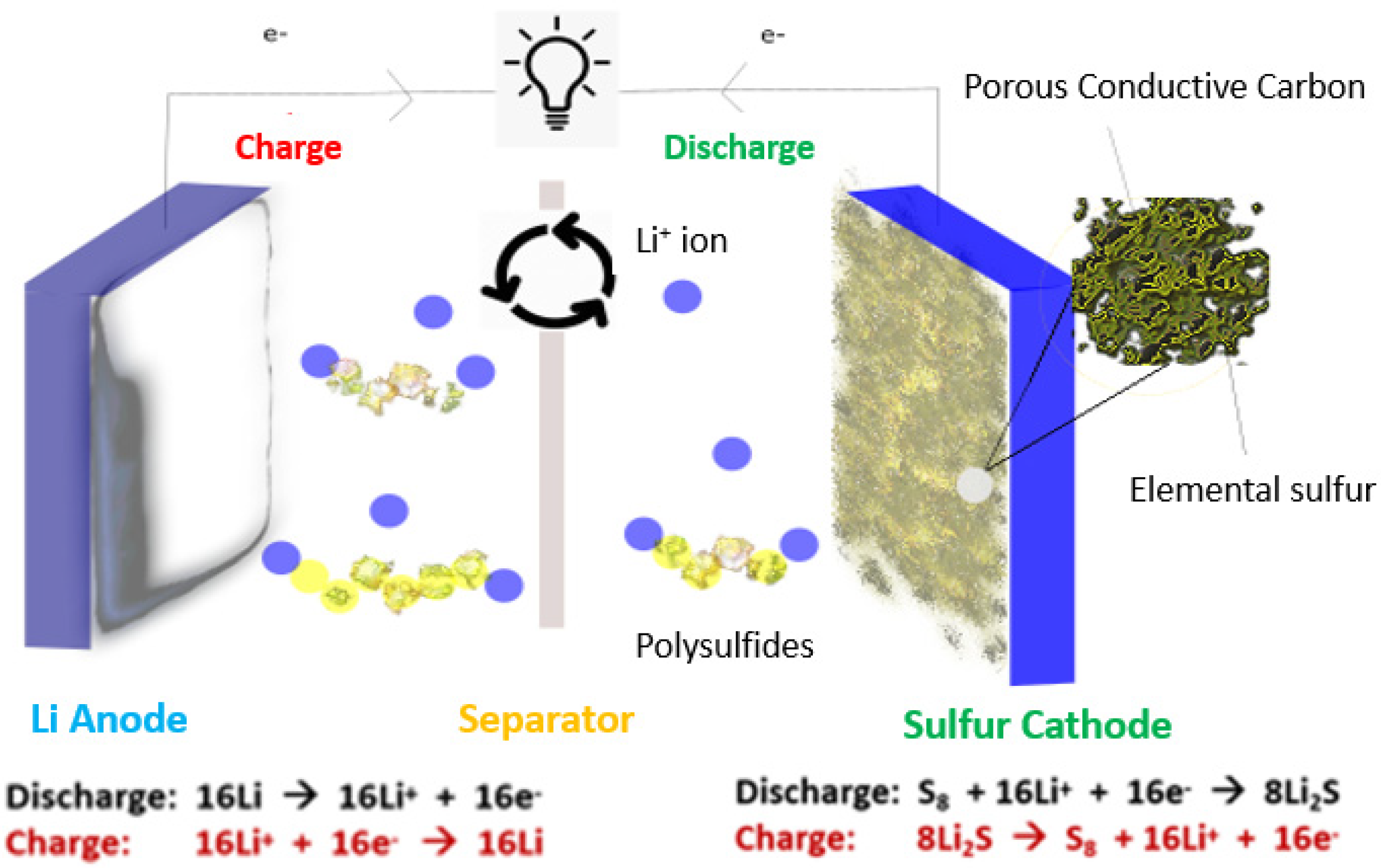
Figure 1. Schematic of a conventional Li–S cell. During discharge, electrons and lithium ions migrate to the cathode, and lithium ions form polysulfide intermediates with S. During charge, the flow of electrons and ions is reversed, leading to the storage of energy in the cell [8,9,10,11,12].
Batteries 08 00045 g001
Figure 2. Lithium dendrite growth from non-uniform diffusion of lithium ions on the anode during charging [19].
Batteries 08 00045 g002
Figure 3. A typical charge–discharge curve in a Li–S cell [27].
Batteries 08 00045 g003
Figure 4. Schematic of the polysulfide shuttle effect [27].
Batteries 08 00045 g004
Figure 5. The schematic shows the continuous decay of sulfur as a result of the deleterious effects of the polysulfide shuttle [26,27,28].
Batteries 08 00045 g005
Figure 6. Components of a standard Li–S battery electrolyte: 1M LiTFSI in DME/DOL (1:1) with 2 wt.% LiNO3 additive [45,46].
Batteries 08 00045 g006
Figure 7. Schematic depiction of the synthesis of S@HCN@MnO2 [56].
Batteries 08 00045 g007
Figure 8. Electrochemical performance of S@HCN2, S@HCN2@MNO2, and S@HCN1@MnO2 at different current densities [56].
Batteries 08 00045 g008
Figure 9. Schematic depiction of the synthesis steps of S@HCS@AlF3 nanoparticles [8].
Batteries 08 00045 g009
Figure 10. Long-term cycling stability of S@HCS@AlF3 nanocomposite electrode at 1 C [8].
Batteries 08 00045 g010
Figure 11. Schematic depiction of the synthesis of the sulfur–TiO2 yolk–shell [57].
Batteries 08 00045 g011
Figure 12. Schematic illustration for the synthesis of sulfur nanospheres and sulfur nanospheres in ultra-thin δ-MnO2 nanosheet core–shell structure [58].
Batteries 08 00045 g012
Figure 13. Schematic illustration for the synthesis of a sulfur@PTh cathode [59].
Batteries 08 00045 g013
Figure 14. Schematic scheme for the synthesis of hollow core–shell interlinked carbon spheres [60].
Batteries 08 00045 g014
Figure 15. Schematic depiction of the synthetic procedure to S@HCS@TiO2 nanocomposite [10].
Batteries 08 00045 g015
Figure 16. (a) Discharge capacity and Coulombic efficiency of S@HCS@TiO2 nanocomposite at 0.2 C over 100 cycles, (b) long-term discharge capacity vs. cycle number for S@HCS@TiO2 nanocomposite at 1 C, (c) rate capabilities of S@HCS@TiO2 nanocomposite at different rates, and (d) voltage profiles of the first charge–discharge cycles of the S@HCS@TiO2 nanocomposite at various C-rates [10].
Batteries 08 00045 g016
Figure 17. Schematic depiction of synthesis process S@HCS@g-C3N4 nanospheres [11].
Batteries 08 00045 g017
Figure 18. (a) Discharge capacity vs. cycle number for S@HCS@g-C3N4 composite electrode; (b) voltage profiles of the S@HCS@g-C3N4 composite electrode at 0.2 C. (c) Rate performance of S@HCS and S@HCS@g-C3N4 nanocomposite cathodes, (d) long-term capacity retention study of the S@HCS@g-C3N4 cathode at 1 C [11].
Batteries 08 00045 g018
Figure 19. Schematic of a carbon–sulfur nanocomposite made of double-shelled hollow carbon spheres by using SnO2 hollow spheres as the hard template [61].
Batteries 08 00045 g019
Figure 20. Schematic illustration for the dual core–shell-structured S@MWCNT@PPy composite synthesis and discharge process [62].
Batteries 08 00045 g020
Figure 21. Schematic depiction of the synthesis steps of S@HCNR@MnO2 nanorods [9].
Batteries 08 00045 g021
Figure 22. (a) Cycling performance and Coulombic efficiency of the S@HCNR@MnO2 electrode at a current rate of 0.2 C, (b) the voltage profiles of the S@HCS@MnO2 electrode at 0.2 C, (c) comparison between rate performance of S@HCNR@MnO2 and S@HCNR nanorod electrodes at different charge–discharge rates, and (d) first charge–discharge profiles of the S@HCS@MnO2 cathode at different C-rates [9].
Batteries 08 00045 g022
Figure 23. Synthetic scheme to fabricate functional FeWO4 [63].
Batteries 08 00045 g023
Figure 24. Synthetic scheme to radially oriented open-porous spherical R-rGO/nS structure [64].
Batteries 08 00045 g024
Figure 25. Synthetic scheme of S@MHCS@MnO2 [65].
Batteries 08 00045 g025
Figure 26. Schematic of CNFs infiltrated with S [66].
Batteries 08 00045 g026
Figure 27. Schematic of the preparation of the S@PCNF composite [68].
Batteries 08 00045 g027
Figure 28. Synthesis of the Fe3C-CNF interlayer disc and schematic illustration of its effective trapping of polysulfides to prevent them from migrating [70].
Batteries 08 00045 g028
Figure 29. Schematic depiction of a Li–S cell with CNT films placed on both sides of the separator. The cathode-side CNT film works as a shield for polysulfides, and the anode-side CNT film works as a solid shield to confine Li dendrite growth [73].
Batteries 08 00045 g029
Figure 30. Schematic depiction of the synthesis steps of Co@NHCR-based sulfur cathode [76].
Batteries 08 00045 g030
Figure 31. Schematic scheme for the synthesis of CC@Co3O4-S composite [80].
Batteries 08 00045 g031
Figure 32. The fabrication scheme of the S@CC@MoS2 cathode [81].
Batteries 08 00045 g032
Figure 33. Schematic of the fabrication of S-Mn3O4 composite electrode [82].
Batteries 08 00045 g033
Figure 34. Synthetic scheme for S@ACC@Ni12P5.
Batteries 08 00045 g034
Figure 35. (a) Long-term discharge capacity and Coulombic efficiency of S@ACC@Ni12P5 at 0.2 C for over 350 cycles; (b) rate capabilities of S@ACC@Ni12P5 at different rates.
Batteries 08 00045 g035
Figure 36. The most popular carbon host materials for sulfur [89,90,91,92,93,94,95,96,97].
Batteries 08 00045 g036
Figure 37. Li2S6 polysulfide adsorption using various metal oxides as tested by ICP-AES [116].
Batteries 08 00045 g037
Figure 38. Structures of polymeric polysulfide absorptive materials [118].
Batteries 08 00045 g038
Figure 39. Synthesis of AFB for polysulfide binding [119].
Batteries 08 00045 g039
Figure 40. Synthesis of the PEDOT:PSS-coated CMK-3/sulfur composite for enhancing the cathode performance. Polysulfides can be confined within the carbon matrix with a conductive polymer coating layer (blue-colored outer layer). Lithium ions and electrons can freely move through this polymer layer [124].
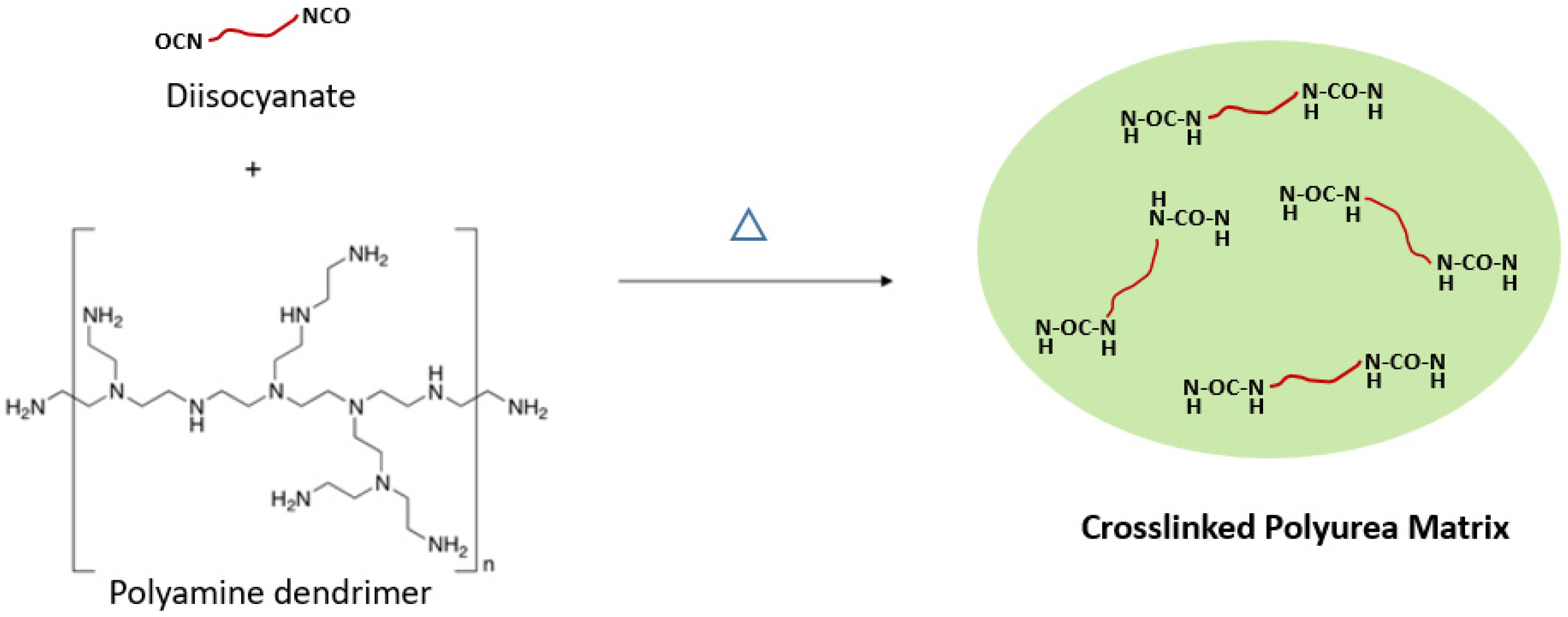
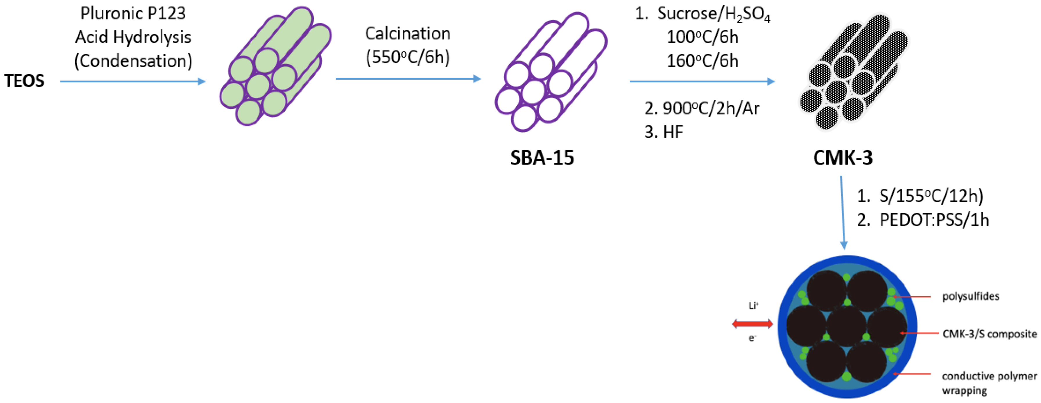
Batteries 08 00045 g040
Figure 41. Schematic of sulfur electrodes with PVDF and PEB-1 binders [126].
Batteries 08 00045 g041
Figure 42. Cell construction depiction with an uncoated Celgard 2400 separator (left) and SPEEK/Nafion-coated separator (right) [137].
Batteries 08 00045 g042
Figure 43. Silicon nanowire (SiNW)/carbon anode [175].
Batteries 08 00045 g043
Figure 45. Schematic of the designed full cell employing a lithiated Si/C–MoS3/rGO electrode [203].
Batteries 08 00045 g045
Table 1. Specific capacity of a Li–S cell by the discharge reactions [24].
Discharge ProductTransferred Electron Number (mol mol−1 S)Depth of Discharge (%)Specific Capacity
(mA h g−1)
S8 → S82−0.2512.5210
S82 → S62−0.3316.7280
S62− → S42−0.525420
S42− → Li2S2125835
Li2S2 → Li2S21001675
Table 2. Current cathode materials used in rechargeable batteries [32].
CathodeRedox CoupleVoltage (V)Theoretical Specific Capacity (mA h g−1)
LiCoO2Co4+/Co3+3.6274
LiNiO2Ni4+/Ni3+4274
LiMn2O4Mn4+/Mn3+3.9148
LiFePO4Fe3+/Fe2+3.5170
SulfurS/Snx−/S2−2.11675
Table 3. List of most common solvents used in Li–S battery electrolytes and their molecular structures [42,43,44].
Batteries 08 00045 i001
SolventMW
(g mol−1)
Density
(g mL−1)
BP (°C)MP (°C)Dielectric Constant
(ε)
Viscosity (cP)
1,3 Dioxolane74.081.06075−957.100.59
Tetraethylene glycol dimethyl ether222.281.009275−307.713.25
Diethylene glycol dimethyl ether134.170.943162−647.271.00
1,2 Dimethoxy ethane90.120.86785−586.990.42
Table 4. Properties of selected sulfur/graphene composite cathodes.
CathodeSulfur (wt.%)PreparationElectrolyte/BinderPerformance (mA h g−1)Cycle Rate (C)Last Cycle No.Ref
Sulfur carboxylated graphene80ChemicalLiTFSI in DOL&DME/PVDF12560.1200[98]
Sulfur/polyacrylonitrile/graphene80.9ThermalLiPF6 in EC&DMC/PTFE12000.150[99]
Sulfur hydroxylated graphene80ChemicalLiCF3SO3 in DOL&DME/PVDF10210.5100[100]
Nafion-coated FGSS79.2ThermalLiTFSI in DOL&DME/PVDF9600.1100[101]
Sulfur/graphene oxide69.7ThermalLiTFSI in PYR14TFSI&PEGDME9540.150[102]
Graphene/sulfur graphene70ThermalLiTFSI in DOL&DME/PVDF8870.2200[103]
CTAB coated sulfur/graphene oxide70ThermalLiTFSI in PYR14TFSI&DOL&DME/SBR&CMC7400.021500[104]
Sulfur/graphene nanosheets81.8ThermalLiTFSI in PEGDME 500/PVDF6000.0340[105]
Graphene-enveloped sulfur89.7ChemicalLiTFSI in DOL&TEGDME5500.250[106]
Graphene/PEG wrapped sulfur80ChemicalDOL&DME5500.5140[107]
Table 5. Pore volume vs. sulfur loading table.
Pore Volume
(cm3 g−1)
Max. S Loading (%)Max. S Loading (%)
with 80% Space
1.5376.063.8
1.8078.867.4
2.0080.569.7
2.1181.370.8
2.3082.672.6
2.5083.874.2
2.7585.176.0
3.0086.177.5
3.2587.178.6
3.5087.980.1
Table 6. Electrochemical properties of Li2S/conductive material composites.
CathodeLi2S Loading (mg cm−2)Activation Barrier@Rate (V)@(C)Initial Discharge Capacity@Rate (mA h g−1)@(C)% Capacity Retention@Cycle NoRef.
3D CoS-C/Li2S8[email protected][email protected]90@200[183]
Li2S/C ethanol1.2–2[email protected][email protected]32@100[184]
Li2S/C amorphousNA[email protected][email protected]76@36[185]
Li2S/C LiI0.8[email protected][email protected]92@100[186]
Li2S/C3–3.5[email protected][email protected]59@200[187]
Li2S/C mix1–1.5[email protected][email protected]48@50[188]
C@Li2S0.75[email protected][email protected]90@100[189]
Li2S@graphene10[email protected][email protected]67@200[190]
VS2-Li2S0.9–1.1[email protected][email protected]84@300[191]
PDSe-Li2S1[email protected][email protected]80@200[192]
Li2S/C DmFc3[email protected][email protected]67@150[193]
LiTiO2/Li2S1.2[email protected][email protected]88@400[194]
Fe-doped Li2S3[email protected][email protected]69@10[195]
Li2S/Ti3C2TX1.6[email protected][email protected]75@100[196]
Li2S@N,P-C1.2[email protected]650@172@300[197]
Li2S/C AQT4[email protected][email protected]70@100[198]
Li2S/C Li3PS41.5[email protected][email protected]67@100[199]
Li2S/C ball-milled0.54[email protected][email protected]74@50[200]
Li2S/rGO1.4[email protected][email protected]63@100[201]
Publisher’s Note: MDPI stays neutral with regard to jurisdictional claims in published maps and institutional affiliations.