Article

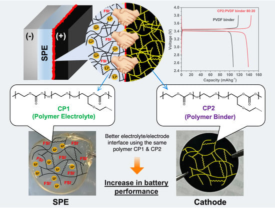
Improvement of the Electrode–Electrolyte Interface Using Crosslinked Carbonate-Based Copolymers for Solid-State Lithium-Ion Batteries

Graduate School of Bio-Application and System Engineering (BASE), Tokyo University of Agriculture and Technology, 2-21-16 Nakacho, Koganei, Tokyo 184-8588, Japan
*
Author to whom correspondence should be addressed.
Batteries 2022, 8(12), 273; https://doi.org/10.3390/batteries8120273
Submission received: 26 September 2022 / Revised: 4 November 2022 / Accepted: 21 November 2022 / Published: 5 December 2022
(This article belongs to the Special Issue Lithium-Ion Battery Energy Storage Technology)

Abstract

:
To enhance the stability and capacity of discharge in a solid-state battery system, we created a design that uses the same carbonate-based copolymer for a solid polymer electrolyte (SPE) and a polymer binder in a cathode. Here, we report on the crosslinked copolymer at different mol% of the allyl side group and the obtained crosslinked copolymer at 4.0 mol% (CP1) and 7.7 mol% (CP2) of the allyl side group, which were characterized by using NMR, TG/DTA, DSC, and a tensile test. The results show that CP1 and CP2 had better mechanical and thermal properties than the carbonate polymer. The superior thermal resistance behavior and good mechanical properties of the crosslinked carbonate-based copolymer were confirmed and were promising under high temperatures and longer cycles than the original copolymer electrolyte at the same salt concentration of 80 mol%. The results reveal that the addition of a crosslinked carbonate-based copolymer for the binder increased the discharge capacity by as much as 140 mAh g−1 because of the reduced resistance, which was confirmed by electrochemical impedance spectroscopy (EIS), while the PVDF binder at 100% of the cathode provided a change of only 107 mAh g−1. This research shows that using the same polymer for a binder and an SPE as a homogenous system can potentially improve a battery’s performance.

Graphical Abstract

1. Introduction

Due to the recent advances in the electronics industry, unique demands for portable and flexible electronic devices or wearable devices such as mobile phones, smartwatches, and electronic clothes have been foreseen. These wearable devices require a safe battery for human applications. Furthermore, the battery must be durable and comply with uses such as bending, stretching, and twisting without reducing battery performance [1,2]. Generally, poly(vinylidene fluoride) (PVDF) has been used as a binder in the positive electrode of a rechargeable battery, and all battery materials have been assembled in the electrolyte solution. However, the PVDF binder has low conductivity due to its crystalline property, which prevents the continuous migration of ions [3,4]. In addition, the liquid leakage and flammable problems of organic solution electrolytes may occur after a battery has been used. The solid-state lithium-ion battery (SSLB) is a candidate for preventing the hazards associated with liquid organic lithium-ion batteries. It has received wide attention in recent decades due to its excellent potential energy density and safety [5]. Recently, SSBLs have been extensively studied for their higher capacity and stability for long-term use, and many researchers have focused on developing ionic conductivity, solid polymer electrolyte materials, and interface compatibility with electrodes [6].
Solid electrolytes were recently selected for use in solid-state battery systems to reduce the battery’s weight and improve its safety, by methods such as using a polymer system for the electrolyte, known as a solid polymer electrolyte (SPE) [7,8]. Poly(ethylene oxide) (PEO) is a promising candidate for use as a polymer matrix because of its low glass transition temperature (Tg) and its high salt solubility and fast ionic migration in the segment motion of a PEO chain, as well as its development as a single-ion conductor [9,10]. However, the increased addition of salts to the PEO and the increase in the Tg leads to a reduction in ionic conductivity because the formation of a highly crystalline complex affects ionic migration [11]. To overcome these problems, polycarbonate polymers such as poly(ethylene carbonate) (PEC), poly(propylene carbonate) (PPC), and other aliphatic polycarbonates are currently attracting much attention as novel polymer matrixes for SPE [12,13].
The carbonate unit of a copolymer has a unique behavior in creating the SPE, because the carbonate group allows the high solubility of salts, and the addition of salts gives rise to the decrease in the Tg, unlike the ether system [14]. The poly(carbonate) system has notable properties for preparing an SPE, but the mechanical and ionic conductivity properties are the primary problems of carbonate-based polymers. A study on a poly(carbonate) SPE revealed that the discharge capacity of a PEC-based SPE dropped suddenly after a few cycles, which may have been due to the degradation of the polymer by the alkoxide backbiting reaction [15]. Recently, a new polymer candidate for SPEs has been shown to achieve flexibility and good ionic conductivity for a random copolymer carbonate of an ethylene ether P(EC/EO) due to the carbonate group’s ability to provide ionic transference and the ether group’s ability to promote ion motion via the ether chain [16]. Recently, it was reported that a P(EC/EO) copolymer with 120 mol% of LiFSI and 53% EO content has good conductivity properties, reaching 2.9 × 10⁻⁴ S cm−1 [16]. Although the copolymer electrolyte provided good ionic conductivity, it was obtained as a gel-like soft solid and as a result, the long-term stability of the battery was affected by its low mechanical properties. To improve the mechanical strength and thermal properties of copolymers, those with allyl glycidyl ether (AGE) side groups for forming the crosslinking structure have been synthesized and their electrolyte properties have been reported [17]. Our reported results of a promising crosslinked copolymer (CP) show that the degradation temperature of the crosslinking copolymer is higher than 200 °C, which is approximately 50 °C higher than that of a neat PEC, and it is obvious that the copolymer’s heat resistance was improved.
Herein, with different ratios of monomer units, CP1 and CP2 have been synthesized for use as SPE matrixes and as polymer binders for a cathode for the first time. The use of the same polymer system in the binder and the electrolyte can reduce the resistance of the electrode–electrolyte interface and may lead to a smooth redox reaction of the ions.

2. Materials and Methods

Ethylene oxide (EO, Air Water Inc., Osaka, Japan 99.9%) and CO2 (99.99%) allyl glycidyl ether (AGE, TCI Co., Tokyo, Japan) were used as received. Other materials, such as 2,2′-azobisisobutyronitrile (AIBN, TCI Co., Tokyo, Japan), lithium bis(fluorosulfonyl) imide (LiFSI, battery-grade, Kishida Chemical Co., Osaka, Japan), LiFePO4 (LFP, Daido Fine Chemicals Co., Hyoko, Japan), poly(vinylidene fluoride) (PVdF, ARKEMA Co., Colombes, France), acetylene black (AB, Denka Black®, Denka Co., Tokyo, Japan), N-methyl pyrrolidone (NMP, >99.5%, Kanto Chemical Co., Tokyo, Japan), and acetonitrile (AN, 99.5%, dehydrated, Kanto Chemical Co., Tokyo, Japan) were used as received.

2.1. Synthesis of Crosslinked Carbonate-Based Copolymer

As reported previously on the synthesis of a carbonate-based crosslinked copolymer [14], our methods proceeded as follows: The copolymerization of EO with CO2 was performed in the presence of a DMC catalyst (0.5 mmol to the EO mol content) at various AGE concentrations in a stainless-steel vessel. The reaction was carried out at 60 °C for 20 h under stirring with CO2 at a pressure of 4 MPa. The received copolymer was purified and dried in an Ar-filled glove box for 48 h. Afterward, the sample was dried in a vacuum oven at 60 °C for 25 h. Then, the starting copolymer was crosslinked using the 2 mol% of AIBN in a vacuum oven at 60 °C for 48 h. The resulting CP1 and CP2 contained the side chain AGE units with 4.0 mol% and 7.7 mol%, respectively.

2.2. Preparation of SPE Using CP1

The starting copolymer with 4.0 mol% of AGE was used to make CP1 as an SPE with different LiFSIs of 40, 60, 80, and 100 mol%, and the lithium ions to monomer units of the carbonate groups were 0.4, 0.6, 0.8, and 1.00, respectively. Then, the initiator AIBN was introduced and all substances were dissolved in acetonitrile solution. The mixture was left in a vacuum oven at 60 °C for 48 h for the crosslinking process, as shown in Scheme 1. All adjustments were performed in an Ar-filled box. Afterwards, the CP1-based SPE was dried in the vacuum oven for 25 h before use.

2.3. Preparation of Cathode Using CP2

The cathode was made using LiFePO4 (LFP) with AB and different ratios of CP2:PVDF as binders in weight compositions of LFP/AB/PVDF/CP2 = (80/10/10x/x). The binder polymer substance CP2:PVDF was investigated in various concentrations of 0:100, 20:80, 50:50, 80:20, and 100:0. The starting copolymer and AIBN were dissolved in an NMP solution, and the mixture was left in a vacuum oven for 48 h for the crosslinking process. PVDF, LFP (0.8 g), and AB (0.1 g) were then added to the NMP and mixed using a mixing machine to obtain a homogenous slurry. Finally, the slurry was casted on an Al foil with a thickness of 400 μm using a film applicator (Doctor blade No.15593, Yasuda Seiki, Hyoko, Japan) in an Ar-filled glove box and dried for 24 h. The dried cathode was pressed at 70 °C and 10 MPa for 30 mins and cut into a circle shape of 6 mm. The entire cell preparation process is summarized in Figure 1.

2.4. Measurements

The two obtained starting copolymers’ chemical structures were confirmed by 1H NMR measurements. The samples were dissolved in CDCl3, and a JNM-ECX400 (JEOL Co. Ltd., Tokyo, Japan) was used to verify the copolymers’ structures at room temperature. An HLC-8320 GPC EcoSEC (TOSOH Co., Tokyo, Japan) with two columns was employed to investigate the molecular weight of the two starting copolymers, and the samples were dissolved in chloroform (HPLC grade). The measurement conditions were investigated at a liquid flow of 1.0 mL min–1 (polystyrene was used as standard). The tensile tests for CP1 and CP2 were performed by force gage using a ZTA 50 N (Imada Co., Aichi, Japan) at a stretching speed of 10 mm min–1 and a testing length of 2.5 cm. Differential scanning calorimetry (DSC) was performed using a DSC7020 (Hitachi High- Tech Co., Tokyo, Japan) with a temperature in the range of −80 to 80 °C at a heating rate of 10 °C/min. Thermogravimetric analysis (TGA) was carried out using a TG/DTA7200 (Hitachi High-Tech Co., Tokyo, Japan) with a temperature range of 30~500 °C at a heating rate of 10 °C/min. The ionic conductivity tests for all electrolyte samples were carried out on an impedance analyzer SP-150 (Bio-Logic Co., Seyssinet-Pariset, France) using the complex impedance method with a frequency range of 102 to 106 Hz, and all processes were carried out in an Ar-filled glove box. The morphologies of the cathodes were observed on a scanning electron microscope (SEM) (Eiko Engineering, Co., Ltd., Ibaraki, Japan) at 10 kV. The specimens were sputter-coated with Au before observation. A CR2032 coin cell for the battery tests was assembled with a cathode on an SS disk and a 0.4 mm-thick Li anode on the bottom disk, and the cell was prepared in the glove box. The galvanostatic charge–discharge test was performed using a potentiostat/galvanostat VMP-300 (Bio-Logic Inst., Seyssinet-Pariset, France) at 60 °C and the 1/10 C was within a voltage range of 2.5–3.8 V. The cell was maintained at 60 °C for 24 h before beginning measurements. The impedance measurements for the cell were performed at 10 mV with open-circuit conditions, and the frequency varied from 105 to 10−3 Hz. The electrochemical stability of the CP1 SPE was conducted with linear sweep voltammetry at 60 °C with a sweep rate of 1 mV/s. The measured cells were composed of stainless steel (SS disk)|SPE|lithium sheets, with a PP sheet as the separator.

3. Results and Discussion

3.1. Physicochemical Properties of the Polymers and Their Electrolytes

The 1H NMR spectra (Figure S1) results of the EO copolymerization with different AGE contents for CP1 and CP2 showed: (a) the CH2 group between the carbonate bond was indicated at 4.36 ppm, (b) the chemical shift at 4.28 ppm was assigned to the CH2 group between the carbonate–ether bond (carbonate side), (c) the CH2 group of the carbonate–ether bond near the ether site was related at 3.71 ppm, and (d) the peak shift at 3.63 ppm represented the CH2 group between the ether–ether bond, as previously reported [17]. The allyl side group was characterized at a peak shift area of 5.0–6.2 ppm as follows: one proton of methylene in the allyl group was assigned at 5.86 ppm and two protons of methylene in the allyl group terminal were assigned at 5.23 ppm. The chemical and physicochemical properties of the crosslinked CP1 and CP2 were investigated, and the results are summarized in Table 1. The results of the calculation of the NMR integration from each peak show that the CP1 with a 50:1 mol% ratio of starting EO:AGE provided the product composition EC:EO:AGE = 53.4:42.6:4.0, while the CP2 with a 20:1 mol% ration of the EO:AGE provided an EC:EO:AGE product ratio of 62.3:30.0:7.7, and both of the synthesized polymers had molecular weight values of more than 100,000.
The results of the DSC measurements for CP1 and CP2 are shown in Figure S2. The Tg value of CP1 was −22 °C, while the increase in the amount of the AGE unit of CP2 decreased the Tg to −24 °C. The decrease in Tg value indicated that there may have been a slightly more amorphous phase in the CP2 due to the provision of more crosslinked regions that were related to the degradation. The TG/DTA measurement data are summarized in Table 1, and they show that CP2 certainly had a high decomposition temperature, which was higher than that of CP1 and the neat PEC [18] because the back-biting reaction usually occurs in the aliphatic terminal in the polycarbonate and generates the ring-carbonate form [19].
Since the synthesized copolymer in this study contained the EO and AGE units for providing the crosslinking bonding structure, it could refrain from the back-biting reaction, resulting in an improvement in heat resistance. Accordingly, CP2 decomposed at a temperature of 230 °C, which was 11 °C higher than that of CP1 due to the increased AGE ratio, which was related to the mechanical strength of the crosslinked copolymer. Five samples of CP1 and CP2 were studied for the tensile tests (Figure S3). The average values of Young’s modulus were estimated from the slopes of the stress–strain curves at the initial elongation, and the data are summarized in Table 1. CP2, having had a higher AGE unit, showed a higher Young’s modulus. Meanwhile, the lower AGE content provided a lower strength for the crosslinked polymer, and CP1 was shown to contain a larger EO unit. The ether unit is considered to be the soft segment, which can make the polymer and the crosslinked copolymer more flexible.
The CP1- and CP2-based SPEs were prepared with different salt concentrations and their thermal properties were investigated, as shown in Table 2. The decrease in Tg in these two electrolytes was clearly confirmed, which means that the C=O···Li+ interaction between the polymer chains and ions may have been reduced by the plasticizing effect of the dissociated FSI anions [20,21,22]. When salt was added to the 100 mol%, the Tg value of CP2 became lower than that of CP1 because this behavior was also seen in the carbonate group. Thus, CP2 contained more carbonate groups in its structure, with a strong dipole moment, and it could dissolve many types of salt. However, at the 40 mol% of the LiFSI in the CP2 system, the Tg of the SPE increased to −17 °C, which may have been due to the salt ions interacting with the ether chain that prevented the segment motion, giving rise to the crystallinity. Upon further study of the thermal behavior, the TGA thermogram showed a decrease in degradation temperature (Td) (Td represents the temperature that the polymer could resist before the main chain was unzipped and depolymerization began, and the Td was estimated at 5%wt loss of a sample) with an increasing salt concentration, which was considered to be due to an increase in the amorphous phase of the polymer. In addition, the decreased Tg represented the increase in the amount of amorphous phase in the polymer’s structure that could allow for a good migration of the ions. In comparing the degradation temperatures of all electrolytes for CP1 and CP2, CP2’s salt concentrations were shown to be higher than those of CP1. The effect of the crosslinked structure may have been positive on the polymer’s thermal behavior. These results verify that CP2 had more crosslinked parts in its framework, which provided good heat resistance. A general decrease in Td5 could be observed when the salt concentration increased, indicating the Tg of the SPE samples in which the plasticizing effect had occurred.

3.2. Ion-Conductive Properties

To investigate the ion-conductive properties at different salt concentrations, temperature dependences were exhibited as the Vogel–Tammann–Fulcher (VTF) behavior, as seen in Figure 2. With increases in the salt concentrations for both the CP1 and CP2 electrolyte systems, the changes in the conductivity were significantly induced. The conductivity of both SPEs increased when the salt concentrations increased from 40 mol% to 100 mol%, as shown in Figure 2. Figure 2a shows that when the salt concentration was increased in CP1, the conductivity increased from 1.1 × 10⁻⁶ S cm−1 (40 mol% of LiFSI) to 1.0 × 10⁻⁵ S cm−1 (100 mol% of LiFSI) at the considered temperature that the coin cell was performed at (60 °C). Meanwhile, the conductivity of CP2 (Figure 2b) was 1.6 × 10⁻⁷ S cm−1 at 40 mol% of LiFSI and increased to 8.9 × 10⁻⁶ S cm−1 at 100 mol% of LiFSI at 60 °C. As a result, even though the CP2 electrolyte had a lower Tg than CP1, as shown in Table 2, any salt concentration of CP1 showed higher conductive properties than the same for CP2. This comparison revealed that even the CP2 electrolytes had lower Tg values due to their crosslinked structure, and the amount of ether units in the polymer was another important factor that could lead the polymers’ properties to include high ionic conductivity.

3.3. Morphology Observations of Cathode Surface

For the investigations of the morphologies of the cathodes, magnification SEM images of four cathodes with different ratios of binders were analyzed, and they are shown in Figure 3. An SEM image of a PVDF binder 100% cathode (as seen in Figure 3a) shows that the surface has cracks. Furthermore, as shown in the SEM image of this sample (Figure S5a), the surface appeared to be rough, the particles were not very well dispersed, and some of the particles had agglomerated. The cracked and rough particles were further confirmed in the cross-section SEM images of the PVDF binder 100% cathode, as seen in Figure S6a. After the CP2 was blended into the PVDF, the cathode surface materials became smoother. The blended cathode at 20:80, 50:50, and 80:20 provided a well surface with a good dispersion of LFP without any cracks, which was confirmed by the overall surface shown in Figure S5. Additionally, in the supporting information in Figure S6, cross-section images of the CP2 binder cathode further confirmed that after adding CP2 to the PVDF, the cathode layer seemed to be smooth (rather than the PVDF binder 100% cathode). To confirm the dry thickness of the cathodes, the thickness lengths were estimated. The average dry thicknesses of the cathodes for CP2:PVDF 0:100, 20:80, 50:50, 80:20, and 100:0 were approximately 60, 40, 25, 20, and 15 μm, respectively. The results reveal that the blending of CP2 binder could provide good adhesion for the active materials and induce them to blend tightly. On the other hand, in images of the 100% crosslinked copolymer-based binder of the cathode (Figure S7 in the supporting information), the many agglomerated particles and some cracks are clearly shown, and this may be due to the heterogeneous morphologies of the crosslinked copolymer with LFP and AB. It is known that the PVDF is a semi-crystalline polymer that is based on a crystalline structure which has the adhesion properties of Al foil [23], and blending it with CP2 can provide better adhesion, which may be related to the increase in the amorphous phase of the mixed polymer phase, improving the adhesion of the cathode materials [24,25].

3.4. Battery Test and Impedance Analysis

Even though an SPE with a salt concentration of 100% has good ion conductive properties, the physical strength of a 100 mol% LiFSI SPE is rather soft and sticky, which is unsuitable for preparation in a battery system. Thus, CP1 at an 80 mol% salt concentration was chosen to be prepared and to investigate the battery system using the various cathodes. Before charge/discharge measurement, the CP1 SPE at an 80 mol% salt concentration was studied to examine the stability of the oxidation reaction. The LSV result in Figure S8 shows that the CP1 SPE had an oxidation stability of up to approximately 4.8 V. To investigate the performance of the prepared cathodes in the battery system, all first charge–discharge profiles were compared, as shown on the left in Figure 4. When the 100% PVDF was used as a cathode binder, the discharge capacity displayed was 107 mAh g−1 (Figure 4a), and this value increased significantly to 140 mAh g−1 in the CP2:PVDF 80:20 system (Figure 4d). According to these results, the voltage profile showed a significant improvement in discharge capacity when the amount of CP2 increased.
The increase in capacity was likely due to the reduction in the interfacial resistance and the induction in fast ionic migration that could be obtained from the Nyquist plots, as shown in Figure 5, and the fitted values are summarized in Table 3 (the EIS values that were fitted follow [26]). After the charging process, the electrode/electrolyte interfacial resistance could be confirmed by analysis of the electrochemical impedance spectroscopy (EIS). The equivalent circuit of the Nyquist plot is described in Figure S9. In general, a Nyquist plot provides the first point at a high frequency, which relates to the bulk resistance (Rb) and reflects the internal resistance, including the electrolyte, electrode/electrolyte, active materials, current collectors, and metallic contact [27,28,29]. The small semicircle indicates the resistance and capacitance of the solid electrolyte interface (RSEI), which represents where the lithium ions’ (de-)intercalation occurs, along with dielectric polarization [29]. A large, partial semicircle next to the resistance of the SEI represents the charge-transfer resistance (Rct), which measures the difficulty encountered by the electron phenomena absorption in the cathode [30,31,32,33]. Finally, the linear part of the EIS at a low frequency is a Warburg impedance, which is related to the possible potential of the charge–discharge capacity [34]. When the amount of CP2 increased, the Rb and Warburg impedance were reduced. The results show that the amount of CP2 increases in the polymer blend system and the electrode/electrolyte interface were more homogenous, leading to the increase in capacity. Thus, the Nyquist plot after the first cycle was related to the capacitance of the ionic storage in the electrode. In this study, when CP2 was used as a polymer binder, it led to a decrease in the RSEI and Rct of the CP2:PVDF 0:100 cell, which may have indicated an improvement in the Li ion migration between the electrolyte phase and the (de-)intercalation of the lithium ions’ pathway in the LFP structure. However, the CP2:PVDF 50:50 showed a lower Rct than that of the CP2:PVDF 80:20 cathode, which may have been due to the surface of the cathode appearing to be more homogenous than that of the CP2:PVDF 80:20, which was confirmed by the SEM image. Even if the homogenous surface affected the electrolyte/electrode resistance, the content of CP2 was also important. Hence, the CP2:PVDF 80:20 had a lower Warburg impedance and its potential discharge capacity was higher than that of the CP2:PVDF 50:50 cathode.
As reported in our previous paper on the P(EC/EO) copolymer electrolytes [16], the results show that the P(EC/EO) (53% EO content) with a salt concentration of 120 mol% displayed a good discharge capacity, close to 160 mAh g−1 at a charging rate of 0.05 C at 40 °C for a few cycles. Although the P(EC/EO) electrolyte displayed good capacity at 40 °C, the performance of the P(EC/EO)-based battery suffered from an elevated temperature at 60 °C. It had difficulty performing at high temperatures because the chain ends of the polymer became active via the thermal energy and initiated a reaction with the carbonate sites in the polymer backbones, leading to back-biting degradation [34]. In this study, the CP1 with 80 mol% of LiFSI was used as an SPE and was available at 60 °C for at least seven to eight cycles. Thus, the CP1-based SPE has a good potential for use as a battery under temperatures higher than room temperature. Furthermore, the results shown in Figure 4 reveal that the crosslinked copolymer can potentially be used for higher temperatures in a battery than the P(EC/EO)-based SPE due to its good thermal properties. However, when the pure CP2 binder was used, it was impossible to measure the battery performance. The cathode of pure CP2 displayed a very low discharge capacity, lower than 1 mAh g−1 (Figure S10), because its heterogenous and rough cathode surface coursed the short circuit that occurred and was supported by the Nyquist plot, as shown in Figure S11. For further consideration of the battery performance, all coin cells were investigated for up to 10 cycles. The cyclability was exhibited as shown in Figure 4, with the coulombic efficiency on the right side, whereas the increase in CP2 provided higher discharge capacities and the coin cells of the CP2:PVDF 20:80 and 50:50 were unstable. Less stability in a battery’s performance might be due to the ratio between CP2 and PVDF, which is not suitable for making a cathode because, in the blending polymer phase, the crosslinked polymer chain was difficult to blend with the linear chain of the PVDF.
With the increase in CP2 content to 80%, the stability of the battery’s performance was improved and the coulombic efficiency (CE) remained higher than 80%. After the 10 cycles, the Nyquist plots in all samples appeared to show the presence of a small semicircle of RSEI and a second semicircle of Rct, which were higher than those of the first cycle. An increase in RSEI with an increasing cycle number suggests that the increase in resistance in the electrode surface was due to the effect of the lithium metal electrode on the SEI’s growth during charging [35]. The growth of the metal electrode layer on the surface affected the decrease in the discharge capacity. In contrast, the CP2:PVDF 20:80 and 80:20 showed reduced Rct values after the tenth cycle, which was related to the SEI layer reforming process, and this behavior was also observed in the study by Zhang et al. [36]. The CP2 binder-loaded cathode system showed the reduction in the second semicircle of Rct, while the PVDF binder 100% system had a large Rct. Therefore, after loading CP2, better interfacial charge transfer effects on the electrode’s surface may have occurred [32,37].

4. Conclusions

In this study, crosslinked EC/EO copolymers (CP1 and CP2) with different molar ratios of the allyl side groups were used as the binder and electrolyte matrixes in a battery system to increase ionic migration. CP1, containing a high molar ratio of EO units and a low number of allyl side groups, had suitable properties for SPE applications. Furthermore, the increase in salt concentration provided better ionic conductivity for CP1 up to 1.0 × 10⁻⁵ S cm−1 at 60 °C. On the other hand, CP2, with high molar ratios of the allyl side and carbonate groups, had good mechanical strength and thermal resistance for use as a polymer binder. The electrochemical performance of a homogenous battery system has been investigated using different CP2:PVDF ratios of CP2 polymer binders for a cathode with an 80 mol% LiFSI of CP1 SPE. Increases in CP2 from 0% to 80% in the cathode revealed that the resistance of the electrode/electrolyte interface was reduced from 204 ohms to 77 ohms, leading to discharge capacity increases as high as 140 mAh g−1. According to these results, the capacitance and stability improved when a carbonate-based copolymer was used in the battery system for at least 7–8 cycles, with the coulombic efficiency remaining at more than 80% at 60 °C. It was indicated that the crosslinked carbonate-based copolymer had the potential to provide more stability, allowing it to resist polymer degradation under high heat conditions. This study reveals that the same polymer may be used as a binder and an SPE in a homogenous system for increases in ionic migration, leading to a higher battery performance in the future.

Supplementary Materials

The following supporting information can be downloaded at: https://www.mdpi.com/article/10.3390/batteries8120273/s1, Figure S1: 1H NMR spectra of synthesized starting copolymers for (a) CP 1 and (b) CP2, respectively; Figure S2: (a) DSC curves and (b) TGA thermograms of CP1 and CP2; Figure S3: Tensile stress-strain curves of CP1 and CP2; Figure S4: DSC curves of (a) CP1 and (b) CP2 with different concentrations; Figure S5: SEM images of (a) CP2:PVDF 0:100, (b) CP2:PVDF 20:80, (c) CP2:PVDF 50:50, and (d) CP2:PVDF 80:20 cathode, respectively; Figure S6: SEM images of cross-section (a) CP2:PVDF 0:100, (b) CP2:PVDF 20:80, (c) CP2:PVDF 50:50, and (d) CP2:PVDF 80:20 cathode, respectively; Figure S7: SEM images of the (a) surface side (inset: SEM images at the higher magnification for this sample) and (b) cross-section of CP2:PVDF 100:0 cathode; Figure S8: Linear sweep voltammogram of CP1 80 mol% LiFSI at 60 °C and a potential scan rate of 1 mV/s; Figure S9: EIS analysis of Nyquist plot with an equivalent circuit model of CP2:PVDF 80:20 cathode after 10th cycle; Figure S10: Voltage profiles of 1st charge-discharge cycle, discharge capacity, and coulombic efficiency after 10 cycles of coin cells using CP2:PVDF 100:0 cathode; Figure S11: Nyquist plots after 1st of CP2:PVDF 100:0 cathode.

Author Contributions

Conceptualization, Y.T.; methodology, Y.T; software, N.S.; validation, N.S., Y.K. and Y.T.; formal analysis, N.S. and Y.K.; investigation, N.S.; resources, N.S. and Y.K.; data curation, N.S. and Y.K.; writing—original draft preparation, N.S.; writing—review and editing, Y.T.; visualization, N.S. and Y.K.; supervision, Y.T.; project administration, Y.T.; funding acquisition, Y.T. All authors have read and agreed to the published version of the manuscript.

Funding

This work was supported financially by a Grant-in-Aid for Scientific Research (B) of JSPS KAKENHI (No. 22H01789), Japan.

Data Availability Statement

All collected data are presented in the manuscript.

Conflicts of Interest

The authors declare no conflict of interest.

References

  1. Lu, C.; Chen, X. Latest Advances in Flexible Symmetric Supercapacitors: From Material Engineering to Wearable Applications. Acc. Chem. Res. 2020, 53, 1468–1477. [Google Scholar] [CrossRef] [PubMed]
  2. Zhao, Y.; Guo, J. Development of flexible Li-ion batteries for flexible electronics. InfoMat 2020, 2, 866–878. [Google Scholar] [CrossRef] [Green Version]
  3. Khamnantha, P.; Homla-Or, C.; Suttisintong, K.; Manyam, J.; Raita, M.; Champreda, V.; Intasanta, V.; Butt, H.-J.; Berger, R.; Pangon, A. Stable Lignin-Rich Nanofibers for Binder-Free Carbon Electrodes in Supercapacitors. ACS Appl. Nano Mater. 2021, 4, 13099–13111. [Google Scholar] [CrossRef]
  4. Watanabe, M.; Kanba, M.; Matsuda, H.; Tsunemi, K.; Mizoguchi, K.; Tsuchida, E.; Shinohara, I. High Lithium Ionic-Conductivity of Polymeric Solid Electrolytes. Makromol. Chemie-Rapid Commun. 1981, 2, 741–744. [Google Scholar] [CrossRef]
  5. Chen, Y.; Wen, K.; Chen, T.; Zhang, X.; Armand, M.; Chen, S. Recent progress in all-solid-state lithium batteries: The emerging strategies for advanced electrolytes and their interfaces. Energy Storage Mater. 2020, 31, 401–433. [Google Scholar] [CrossRef]
  6. Guo, Y.; Wu, S.; He, Y.-B.; Kang, F.; Chen, L.; Li, H.; Yang, Q.-H. Solid-state lithium batteries: Safety and prospects. eScience 2022, 2, 138–163. [Google Scholar] [CrossRef]
  7. Scrosati, B.; Garche, J. Lithium batteries: Status, prospects and future. J. Power Sources 2010, 195, 2419–2430. [Google Scholar] [CrossRef]
  8. Muldoon, J.; Bucur, C.B.; Boaretto, N.; Gregory, T.; DI Noto, V. Polymers: Opening Doors to Future Batteries. Polym. Rev. 2015, 55, 208–246. [Google Scholar] [CrossRef]
  9. Xue, Z.; He, D.; Xie, X. Poly(ethylene oxide)-based electrolytes for lithium-ion batteries. J. Mater. Chem. A 2015, 3, 19218–19253. [Google Scholar] [CrossRef]
  10. Luo, J.; Sun, Q.; Liang, J.; Yang, X.; Liang, J.; Lin, X.; Zhao, F.; Liu, Y.; Huang, H.; Zhang, L.; et al. A liquid-free poly(butylene oxide) electrolyte for near-room-temperature and 4-V class all-solid-state lithium batteries. Nano Energy 2021, 90, 106566. [Google Scholar] [CrossRef]
  11. Li, X.; Zhang, Z.; Li, S.; Yang, K.; Yang, L. Polymeric ionic liquid–ionic plastic crystal all-solid-state electrolytes for wide operating temperature range lithium metal batteries. J. Mater. Chem. A 2017, 5, 21362–21369. [Google Scholar] [CrossRef]
  12. Zhao, Y.; Wang, L.; Zhou, Y.; Liang, Z.; Tavajohi, N.; Li, B.; Li, T. Solid Polymer Electrolytes with High Conductivity and Transference Number of Li Ions for Li-Based Rechargeable Batteries. Adv. Sci. 2021, 8. [Google Scholar] [CrossRef]
  13. Rollo-Walker, G.; Malic, N.; Wang, X.; Chiefari, J.; Forsyth, M. Development and Progression of Polymer Electrolytes for Batteries: Influence of Structure and Chemistry. Polymers 2021, 13, 4127. [Google Scholar] [CrossRef]
  14. Zhang, J.; Zhao, J.; Yue, L.; Wang, Q.; Chai, J.; Liu, Z.; Zhou, X.; Li, H.; Guo, Y.; Cui, G.; et al. Safety-Reinforced Poly(Propylene Carbonate)-Based All-Solid-State Polymer Electrolyte for Ambient-Temperature Solid Polymer Lithium Batteries. Adv. Energy Mater. 2015, 5, 1501082. [Google Scholar] [CrossRef]
  15. Li, X.; Meng, Y.; Zhu, Q.; Tjong, S. Thermal decomposition characteristics of poly(propylene carbonate) using TG/IR and Py-GC/MS techniques. Polym. Degrad. Stab. 2003, 81, 157–165. [Google Scholar] [CrossRef]
  16. Tominaga, Y.; Nakano, K.; Morioka, T. Random copolymers of ethylene carbonate and ethylene oxide for Li-Ion conductive solid electrolytes. Electrochimica Acta 2019, 312, 342–348. [Google Scholar] [CrossRef]
  17. Nishimura, N.; Hashinokuchi, J.; Tominaga, Y. Thermal, Mechanical, and Ion-Conductive Properties of Crosslinked Poly[(ethylene carbonate)-co-(ethylene oxide)]-Lithium Bis(fluorosulfonyl)imide Electrolytes. Macromol. Chem. Phys. 2021, 223, 2100327. [Google Scholar] [CrossRef]
  18. Metz, S.; Jiguet, S.; Bertsch, A.; Renaud, P. Polyimide and SU-8 microfluidic devices manufactured by heat-depolymerizable sacrificial material technique. Lab Chip 2004, 4, 114–120. [Google Scholar] [CrossRef]
  19. Darensbourg, D.J.; Wei, S.-H.; Wilson, S.J. Depolymerization of Poly(indene carbonate). A Unique Degradation Pathway. Macromolecules 2013, 46, 3228–3233. [Google Scholar] [CrossRef]
  20. Dragunski, D.; Pawlicka, A. Starch Based Solid Polymeric Electrolytes. Mol. Cryst. Liq. Cryst. 2002, 374, 561–568. [Google Scholar] [CrossRef]
  21. Saikaew, R.; Meesorn, W.; Zoppe, J.O.; Weder, C.; Dubas, S.T. Influence of the Salt Concentration on the Properties of Salt-Free Polyelectrolyte Complex Membranes. Macromol. Mater. Eng. 2019, 304, 1900245. [Google Scholar] [CrossRef]
  22. Kobayashi, K.; Pagot, G.; Vezzù, K.; Bertasi, F.; Di Noto, V.; Tominaga, Y. Effect of plasticizer on the ion-conductive and dielectric behavior of poly(ethylene carbonate)-based Li electrolytes. Polym. J. 2020, 53, 149–155. [Google Scholar] [CrossRef]
  23. Loghavi, M.M.; Bahadorikhalili, S.; Lari, N.; Moghim, M.H.; Babaiee, M.; Eqra, R. The Effect of Crystalline Microstructure of PVDF Binder on Mechanical and Electrochemical Performance of Lithium-Ion Batteries Cathode. Z. Für Phys. Chem. 2020, 234, 381–397. [Google Scholar] [CrossRef]
  24. Wang, Y.; Gozen, A.; Chen, L.; Zhong, W. Gum-Like Nanocomposites as Conformable, Conductive, and Adhesive Electrode Matrix for Energy Storage Devices. Adv. Energy Mater. 2016, 7, 1601767. [Google Scholar] [CrossRef]
  25. Wang, Y.; Zhong, W.-H.; Schiff, T.; Eyler, A.; Li, B. A Particle-Controlled, High-Performance, Gum-Like Electrolyte for Safe and Flexible Energy Storage Devices. Adv. Energy Mater. 2014, 5, 1400463. [Google Scholar] [CrossRef]
  26. Shim, E.-G.; Nam, T.-H.; Kim, J.-G.; Kim, H.-S.; Moon, S.-I. Effect of vinyl acetate plus vinylene carbonate and vinyl ethylene carbonate plus biphenyl as electrolyte additives on the electrochemical performance of Li-ion batteries. Electrochimica Acta 2007, 53, 650–656. [Google Scholar] [CrossRef]
  27. Zhang, S.; Xu, K.; Jow, T. Electrochemical impedance study on the low temperature of Li-ion batteries. Electrochimica Acta 2004, 49, 1057–1061. [Google Scholar] [CrossRef]
  28. Tatara, R.; Karayaylali, P.; Yu, Y.; Zhang, Y.; Giordano, L.; Maglia, F.; Jung, R.; Schmidt, J.P.; Lund, I.; Shao-Horn, Y. The Effect of Electrode-Electrolyte Interface on the Electrochemical Impedance Spectra for Positive Electrode in Li-Ion Battery. J. Electrochem. Soc. 2018, 166, A5090–A5098. [Google Scholar] [CrossRef]
  29. Meddings, N.; Heinrich, M.; Overney, F.; Lee, J.-S.; Ruiz, V.; Napolitano, E.; Seitz, S.; Hinds, G.; Raccichini, R.; Gaberšček, M.; et al. Application of electrochemical impedance spectroscopy to commercial Li-ion cells: A review. J. Power Sources 2020, 480, 228742. [Google Scholar] [CrossRef]
  30. Middlemiss, L.A.; Rennie, A.J.; Sayers, R.; West, A.R. Characterisation of batteries by electrochemical impedance spectroscopy. Energy Rep. 2020, 6, 232–241. [Google Scholar] [CrossRef]
  31. Gaberšček, M. Understanding Li-based battery materials via electrochemical impedance spectroscopy. Nat. Commun. 2021, 12, 6513. [Google Scholar] [CrossRef]
  32. Choi, W.; Shin, H.-C.; Kim, J.M.; Choi, J.-Y.; Yoon, W.-S. Modeling and Applications of Electrochemical Impedance Spectroscopy (EIS) for Lithium-ion Batteries. J. Electrochem. Sci. Technol. 2020, 11, 1–13. [Google Scholar] [CrossRef] [Green Version]
  33. Alavi, S.M.M.; Birkl, C.R.; Howey, D.A. Time-domain fitting of battery electrochemical impedance models. J. Power Sour. 2015, 288, 345–352. [Google Scholar] [CrossRef]
  34. Oldenburger, M.; Bedürftig, B.; Gruhle, A.; Grimsmann, F.; Richter, E.; Findeisen, R.; Hintennach, A. Investigation of the low frequency Warburg impedance of Li-ion cells by frequency domain measurements. J. Energy Storage 2018, 21, 272–280. [Google Scholar] [CrossRef]
  35. Parekh, M.N.; Rahn, C.D. Solid Electrolyte Interphase Growth in Lithium Metal Cells With Normal Electrolyte Flow. Front. Chem. Eng. 2022, 4. [Google Scholar] [CrossRef]
  36. Zhang, L.; Zhang, K.; Shi, Z.; Zhang, S. LiF as an Artificial SEI Layer to Enhance the High-Temperature Cycle Performance of Li4Ti5O12. Langmuir 2017, 33, 11164–11169. [Google Scholar] [CrossRef]
  37. Ye, S.; Ding, C.; Chen, R.; Fan, F.; Fu, P.; Yin, H.; Wang, X.; Wang, Z.; Du, P.; Li, C. Mimicking the Key Functions of Photosystem II in Artificial Photosynthesis for Photoelectrocatalytic Water Splitting. J. Am. Chem. Soc. 2018, 140, 3250–3256. [Google Scholar] [CrossRef]
Scheme 1. Crosslinking reaction of the starting copolymer.
Batteries 08 00273 sch001
Figure 1. Illustration of the coin cell preparation using CP1 as an SPE matrix and CP2 as a polymer binder.
Batteries 08 00273 g001
Figure 2. Temperature dependence of ionic conductivity for (a) CP1 and (b) CP2 with LiFSI concentrations of 40 mol%, 60 mol%, 80 mol%, and 100 mol%, respectively.
Batteries 08 00273 g002
Figure 3. SEM images: (a) CP2:PVDF 0:100, (b) CP2:PVDF 20:80, (c) CP2:PVDF 50:50, and (d) CP2:PVDF 80:20.
Batteries 08 00273 g003
Figure 4. Voltage profiles of the first charge–discharge cycle, discharge capacity, and coulombic efficiency after 10 cycles of coin cells using CP2:PVDF ratios as follows: (a) 0:100, (b) 20:80, (c) 50:50, and (d) 80:20.
Batteries 08 00273 g004
Figure 5. Nyquist plots after the first and tenth cycles of CP2:PVDF at the following ratios: (a) 0:100, (b) 20:80, (c) 50:50, and (d) 80:20.
Batteries 08 00273 g005
Table 1. Chemical and physicochemical properties of the crosslinked CP1 and CP2 copolymers.
Crosslinked
Copolymer
Monomers Unit (mol%)MnMwTg (°C)Td5 (°C)Young’s Modulus
(MPa)
Elongation at Break
(%)
ECEOAGE
CP153.442.64.054,466195,462−222190.03121
CP262.330.07.736,623139,820−242300.07119
Table 2. Glass transitions and degradation temperatures of the CP1 and CP2 electrolytes at different salt concentrations.
SampleTg (°C)Td5 (°C)
CP1 original−22219
+40 mol% LiFSI−24154
+60 mol% LiFSI−27152
+80 mol% LiFSI−29144
+100 mol% LiFSI−30142
CP2 original−24230
+40 mol% LiFSI−17181
+60 mol% LiFSI−22183
+80 mol% LiFSI−29159
+100 mol% LiFSI−34146
Table 3. Fitted values from the EIS analysis after the first and tenth cycles, with discharge capacity.
SampleRb
(Ohm)
RSEI (Ohm)Rct (Ohm)Warburg
Impedance
(Ohm)
Discharge Capacity (mAh g−1)
CP2:PVDF 0:100 1st cycle20440463610107
CP2:PVDF 20:80 1st cycle18722460600115
CP2:PVDF 50:50 1st cycle14820283500120
CP2:PVDF 80:20 1st cycle7736369450140
CP2:PVDF 0:100 10th cycles225457209008
CP2:PVDF 20:80 10th cycles1453531048039
CP2:PVDF 50:50 10th cycles1593230446017
CP2:PVDF 80:20 10th cycles15238300450128
Publisher’s Note: MDPI stays neutral with regard to jurisdictional claims in published maps and institutional affiliations.

