Abstract
Various studies show that electrification, integrated into a circular economy, is crucial to reach sustainable mobility solutions. In this context, the circular use of electric vehicle batteries (EVBs) is particularly relevant because of the resource intensity during manufacturing. After reaching the end-of-life phase, EVBs can be subjected to various circular economy strategies, all of which require the previous disassembly. Today, disassembly is carried out manually and represents a bottleneck process. At the same time, extremely high return volumes have been forecast for the next few years, and manual disassembly is associated with safety risks. That is why automated disassembly is identified as being a key enabler of highly efficient circularity. However, several challenges need to be addressed to ensure secure, economic, and ecological disassembly processes. One of these is ensuring that optimal disassembly strategies are determined, considering the uncertainties during disassembly. This paper introduces our design for an adaptive disassembly planner with an integrated disassembly strategy optimizer. Furthermore, we present our optimization method for obtaining optimal disassembly strategies as a combination of three decisions: (1) the optimal disassembly sequence, (2) the optimal disassembly depth, and (3) the optimal circular economy strategy at the component level. Finally, we apply the proposed method to derive optimal disassembly strategies for one selected battery system for two condition scenarios. The results show that the optimization of disassembly strategies must also be used as a tool in the design phase of battery systems to boost the disassembly automation and thus contribute to achieving profitable circular economy solutions for EVBs.
1. Introduction
Electrification of the transport sector is mandatory to achieve the Paris climate targets, as it currently accounts for around 24% of all global CO2 emissions [1]. However, battery electric vehicles (BEVs) currently cause almost twice the greenhouse gas emissions in the manufacturing phase compared to equivalent combustion vehicles, mainly due to the resource-intensive production of the battery [2]. Nevertheless, electric vehicle batteries (EVBs) show a significantly better environmental performance if, first, renewable energy is used to charge the battery during the use phase and, second, if electrification occurs within a circular economy. In this context, the battery plays the most important role, as it is the most expensive component in BEVs and contains valuable materials and components suitable for reuse. A battery pack generally consists of several modules made up of battery cells. Currently, Li-ion cells are the most common. They can be found in three shapes (cylindrical, pouch, and prismatic) with different cell chemistries (NMC, LCO, LMO, LFP, and NCA). However, the general structure of a Li-ion battery cell is independent of the cell format and the used chemistries. Its main components are anodes, cathodes, a separator, an electrolyte, and housing. In batteries for the automotive sector, all cell formats and a wide range of chemistries are used. Thereby, materials’ purchase costs are the primary cost driver.
The circular use of components and materials offers big economic opportunities and has great potential to secure the supply of strategic raw materials for cell manufacturers [3]. The work of Sato and Nakata [4] showed that by 2035, high quantities of critical materials for the production of new Li-ion batteries in Japan will be obtained from the recycling of batteries at the end-of-life (EoL) stage (34% of lithium (Li), 50% of cobalt (Co), 28% of nickel (Ni), and 52% of manganese (M)). However, according to Kotak et al. [5], alternative circular economy strategies such as reuse and remanufacturing would extend the use phase of batteries and thus avoid the resource-intensive production of new batteries. Furthermore, they allow postponing recycling, which will result in improving the recycling efficiency due to the fact that the recycling processes are continuously being developed. In this context, disassembly plays a key role in the implementation of all alternative circular economy strategies at the EoL phase [6]. In addition, by using advanced disassembly technologies and strategies, material recyclers can significantly reduce the mix of materials to be handled in resource-intensive downstream material recycling processes.
Nevertheless, today, disassembly represents a bottleneck process that has to be performed faster [7]. Currently, EVB disassembly is done manually [8], which leads to high costs and poses safety risks to human workers. For these reasons, industrial and highly automated disassembly is mandatory in the future [6]. Automated disassembly is required to handle future quantities of returning battery systems in an economically viable and secure manner. Based on the review of several literature sources, Tan et al. [9] divided the battery disassembly process at the module-level into four steps. It starts with removing the battery casing, followed by the extraction of the battery management system (BMS), power electronics, and the thermal management system. After that, wires, cables, and connectors are removed. Finally, the modules are obtained after disassembling the securing holders. The modules can be further disassembled to obtain the battery cells. Thereby, the five main components have to be removed from the modules. These are cell contacting, cell fixation, housing, thermal management, and the BMS [10]. Gerlitz et al. [10] classified the challenges for automated disassembly at the module level into product-related and process-related challenges. Thereby, the main challenge posed by the product is the design variety. The main process-related challenges are the non-detachable joints and the hazards related to Li-ion batteries.
Figure 1 shows the different players in the life cycle of EVBs and their role in implementing a circular economy. Thereby, disassemblers specify the material flow at the EoL phase. Remanufacturers are very important for implementing high-value circularity solutions at the different system levels. Recyclers are obligatory to close the loop. Here, it is worth mentioning that there are different opinions in the ongoing research projects on who will carry out disassembly, remanufacturing, and recycling. It is assumed that these operations will either be performed by the same stakeholder, such as recyclers, or that new actors will be established due to the expected enormous return volumes and the diversified skills necessary to establish economic and high-quality circularity of EVBs. In this work, we adopt the second opinion. Disassemblers play a decisive role, whatever the recovery option at the EoL phase is. However, EVB disassemblers have to deal with several challenges in the future, such as:
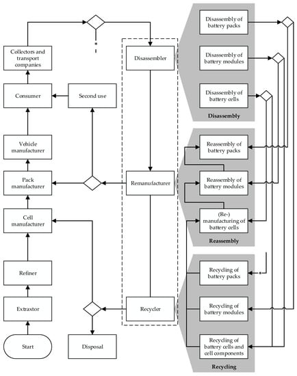
Figure 1.
Participants along the life cycle of battery systems and their role in establishing a circular economy.
- The increasing return volumes, the uncertainties in timing, quality, and quantity leading to uncertainties concerning the economic viability of future circular economy strategies,
- The wide range of battery system designs and cell chemistries and the short innovation cycles for new cell chemistries causing potential technological obsolescence and rapid decay of economic value of battery technologies currently prevalent in the field.
At the EoL phase, remanufacturers and recyclers are also crucial to extend the life of battery components or to recycle the battery parts if recycling is the only recovery option due to advanced aging or if recycling is the most suitable recovery option. The big challenge here is to find out the optimal route for an EVB at the EoL phase, as there are multiple alternative circular economy strategies and diverse recycling paths. Furthermore, this decision depends on the market demand. Therefore, a multicriteria decision platform is extremely essential [1].
Once the optimal EoL strategy has been determined, how should the battery be disassembled to implement the selected route economically? This question leads to an optimization problem that must be solved for individual batteries to significantly increase the economic efficiency of disassembly as the most expensive processing step in the current state [11]. Ke et al. [12] performed disassembly tests on the same battery type with the same skilled workers. They observed that the workers could disassemble the battery at least 11.5% faster when they had an optimized disassembly sequence.
Disassembly cannot be seen as the reverse of assembly because, first, disassembly is subject to many uncertainties and, second, there are different ways to perform disassembly. Here, different disassembly modes can be distinguished using several criteria. such as the disassembly depth (Complete/incomplete), the disassembly techniques (Destructive/non-destructive), the number of used manipulators (Sequential/parallel), and the automation level (Manual/automated). Thereby, disassembly of complex products cannot be performed just experience-based. Disassembly planning solutions that are adaptive and use optimization algorithms are necessary to determine optimal disassembly strategies.
This paper aims to contribute to designing adaptive disassembly planners for battery systems by combining the autonomous disassembly planner presented by Choux et al. [13] with a disassembly strategy optimizer, which will be implemented and tested using an Audi A3 Sportback e-tron hybrid battery pack. The battery, instructions about its disassembly, and several essential data for the disassembly planning, such as the disassembly times and revenues at component level after applying a specific circular economy strategy, have been described in detail in [14]. In this paper, the optimal disassembly strategy maximizes the optimal economic profit. It consists of the following decisions: (1) the optimal disassembly sequence, (2) the optimal disassembly depth, and (3) the optimal circular economy strategy for each component (reuse, remanufacturing, repurposing, and recycling). The proposed disassembly planner can significantly contribute to implementing high-value circularity levels at the EoL phase of EVBs in automated disassembly solutions in the future.
The following sections are organized as follows: Section 2 describes the main components of an automated disassembly solution. Thereby, the disassembly planner with an integrated disassembly strategy optimizer represents a core building block. Section 3 describes our methodology by presenting our design for an adaptive disassembly planner and a disassembly strategy optimizer. Finally, we present and discuss our use case results in Section 4.
2. Building Blocks of an Automated Disassembly Station
An automated disassembly station for EVBs can be reduced to two building blocks: (1) a mechanical system that directly interacts with the EoL products, and (2) a disassembly planner that adaptively calculates and updates the disassembly strategies (see Figure 2). The subcomponents are described in the following sections to show the big picture of our work. Thereby, publications in the context of battery disassembly are assigned to the respective subcomponent.
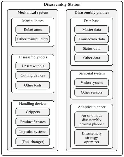
Figure 2.
Building blocks of disassembly stations.
2.1. Mechanical System
2.1.1. Manipulators
Manipulators are responsible for moving several components during the disassembly process. These components can either be part of the battery or the disassembly station, such as tools and sensors. Robot arms are typical manipulators. The disassembly process can be carried out using a single manipulator resulting in a sequential disassembly, in which the parts are removed one by one. However, multiple manipulators have a great potential to reduce the disassembly time if parallel disassembly activities are possible. This is known as corporative disassembly. The disassembly sequence planning is more complicated if more than one manipulator is used [15].
2.1.2. Disassembly Tools
EVBs are complex products whose disassembly is associated with multiple difficulties. Screw connections are frequently found in batteries. This allows the application of non-destructive disassembly. However, different screw types are often used, which are not accessible from the same direction [16]. This means that disassembly involves frequent tool and direction changes, which have to be considered while planning the disassembly process. Furthermore, many non-detachable connections are used in EVBs, such as welded joints. This is especially the case at the module level when connecting the cells [17], where welding processes have become established because they increase the electrical performance and improve the joints’ thermal properties and long-term stability [18]. However, these joints are difficult to disassemble, especially when alternative circular economy strategies are targeted.
Moreover, various other joining techniques are used in the battery, such as adhesive bonding and riveting. In addition, there are several connector systems and flexible components that have to be disconnected or cut. That is why an automated disassembly of EVBs can only be achieved with a wide range of disassembly tools. In the literature, various tools have been presented that can be used in automating individual steps of battery disassembly. Tan et al. [9] presented a pneumatically actuated separation tool suitable for removing covers and stack holders and an unscrewing device with integrated torque sensors. Kay et al. [19] proposed a cost-effective cutting instrument based on a high-speed rotary cut-off wheel, which can be integrated into a disassembly station for battery modules. However, according to their evaluation, laser cutting is more suitable to achieve lower heat generation and vibration amplitudes and higher cutting accuracy. Li et al. [20] proposed an automated disassembly system for Z-folded pouch cells consisting of three modules for the pouch trimming, housing removal, and electrode sorting. Thereby, they presented a pouch trimming module consisting of a trimming blade set, a trimming base set, and a conveyor roller set. In this context, the main challenge in designing disassembly tools will be to develop universal tools that are, first, suitable for different battery variants and, second, capable of performing more than one disassembly task to reduce the number of tool changes during disassembly.
2.1.3. Handling Devices
They can be divided into three categories: grippers, product fixtures, and logistics systems [21]. The tool changer can also be seen as a handling device for the disassembly tools.
- Grippers: These are placed at the end of the manipulator and are used to handle the disassembled parts. They have to deal with objects with different geometries, volumes, weights, and surfaces, as well as with uncertainties concerning these properties, such as modifications in the surface due to usage and aging or contaminations during the disassembly. In the context of battery disassembly, handling flexible parts, such as cables, is a challenging task [16]. In addition, the extraction of the cells is associated with difficulties. This is due to the different cell types (pouch, cylindrical and prismatic cells) and the various design features, such as differences in volume, arrester position, and cell housing. Schmitt et al. [22] presented a flexible gripper with integrated voltage and internal resistance metering for automated handling of pouch cells. The gripper can grasp different cell geometries if the arresters are placed on the same side. Kay et al. [19] proposed a two-finger gripper with integrated force regulation to not damage the battery cells. From these publications, some essential features and requirements for battery cell gripper systems can be derived. These are the ability of condition assessment and monitoring, the handling of different cell formats and sizes, and controlling the gripping force.
- Product fixtures: These are necessary elements of an automated disassembly solution. They are needed to fix the product to be disassembled in a specific position and orientation so that the required forces are transmitted and to increase the process accuracy. Product fixtures can be designed to be stationary or movable. Thereby, the movement can take place with limited degrees of freedom, such as by means of a rotatable or translatory fixture table. They can also be seen as manipulators when they are mounted on a robot arm. In this case, they offer higher degrees of freedom in the positioning and orientation of the products to be disassembled. However, in the context of battery disassembly, this could be associated with technical difficulties. The weight of many EVBs can reach several hundreds of kilograms, which could pose a challenge for their mobile handling by means of robot arms during the disassembly process. Other challenges include the flexibility to clamp as many battery variants as possible. In addition, it must be ensured that the design features of the fixture devices do not prevent the detection of the product parts [21]. Detailed designs of fixture systems for EVBs cannot be found in the literature. This can be explained by the fact that battery disassembly is performed manually in the current state of the art.
- Logistics systems: These are in charge of transporting the products to be disassembled to the disassembly stations and transporting the disassembled parts and subassemblies in and from the disassembly net. Herrmann et al. [23] defined three disassembly scenarios for EVBs dependent on a product analysis and return quantities. In the present scenario, the batteries are disassembled in a single disassembly place. Thereby, the material transportation is carried out by forklifts, which also play a role in the near future and remote future scenarios. They transport the batteries to the disassembly net. The main difference to the present scenario is that the material transport inside the disassembly net is performed by roll conveyors.
2.2. Disassembly Planner
2.2.1. Database
The appropriate disassembly strategy for an individual EVB is the result of an optimization problem under consideration of a wide range of data, which must be available to the disassembly factories in order to increase the efficiency of a circular economy for battery systems. Therefore, structuring and managing these data in a database is of fundamental importance. Thereby, the need-based availability of some information is essential to protect the competitive advantages of battery manufacturers. Relevant data can be divided into process-related data and product-related data. Process-related data are, for example, disassembly times and costs and needed disassembly tools. The product-related data can be further classified into master data, transaction data, status data, and market data [24]. Master data comprise general information about the battery, such as the cell format and chemistry, the number of cells and modules, and information about other battery components, such as the battery management system. For disassembly, the precedence constraints, the joining techniques, the position of parts, and information about their accessibility are particularly important. Transaction data include information about the history of the battery. Status data provide information about the condition of the different components of the battery, such as the state of health of the modules and the cells. Market data are also essential to find out the optimal disassembly strategy. In particular, the potential revenues from selling components after applying a specific EoL strategy, such as remanufacturing, play a role.
2.2.2. Sensorial System
Before disassembly, the information from the database can be expanded with additional data using other sources, such as battery measurements or employees’ experience. Nevertheless, not all the information may be available before starting the process. This is due to the variety of uncertainties during automated disassembly. Therefore, the sensorial system in an automated disassembly solution is mandatory to plan the process and to adapt it at the operational level [21]. Thereby, a vision system is needed to detect the components and their positions and monitor the progress of the disassembly process. In addition, other sensors are required, such as torque and force sensors, which can be used for both process control and monitoring.
2.2.3. Adaptive Planner
The adaptive planner is responsible for planning and optimizing the disassembly strategy. This process is known in the literature as disassembly sequence planning (DSP), and was described in detail in [25]. It finds application in both the planning and operating of disassembly lines, in addition to being used in the product development phase to ensure the guidelines of design for circularity (DfC). DSP starts with selecting the disassembly mode, followed by the modelling step, consisting of the two phases pre-processing and model building. Finally, the disassembly sequence can be optimized while considering a predefined objective function. Many publications have addressed only deriving disassembly sequences. Here, complete disassembly has been considered more frequently than incomplete disassembly [25]. However, the optimal circular economy strategies are supposed to be predefined in the literature and, therefore, are not seen as part of the disassembly planning [26]. An adaptive disassembly planner in an automated disassembly solution consists of an autonomous disassembly process planner that ensures the disassembly execution even when the required data are incomplete and a disassembly strategy optimizer to support decision-making by ensuring that data gaps are eliminated. In this way, different decisions can be made with the help of the optimizer, such as the optimal number of tool and direction changes as well as optimal circular economy strategies at the component level. In the context of battery disassembly, Ke et al. [12] proposed a disassembly sequence planning approach for EVBs based on a genetic algorithm using a frame-subgroup structure. The presented method has better convergence properties compared to other genetic algorithm implementations. However, it requires the existence of a frame (one component) that has connection and precedence relationships with all other parts (subgroups). In addition, only disassembly sequences for a complete disassembly are considered. Incomplete disassembly and decisions about the optimal circular economy strategies at the component level were not taken into account. Choux et al. [13] proposed an autonomous disassembly task planner, which can generate disassembly sequences autonomously. Thereby, no information about the battery to be disassembled is required. However, the completeness of the automatically detected precedence relationships in [14] was not guaranteed. Thus, possible disassembly sequences that may represent an improved disassembly strategy cannot be considered by the adaptive planner. In addition, the proposed task planner cannot make decisions about the disassembly depth and cannot provide information about the circular economy strategies for the different components, while it has been shown in [14] that they are decisive factors for the disassembly planning for EVBs. These disadvantages can be overcome by extending the autonomous disassembly process planner by a disassembly strategy optimizer. This represents the main research focus of this paper.
3. Methodology
3.1. Disassembly Planning Using an Adaptive Planner
The disassembly task planner presented by Choux et al. [13] consists of four steps: (1) image capturing by the installed vision system, (2) detection of the different components of the battery, (3) autonomous decision making about the possible disassembly sequences, and (4) position and path calculation to remove the components by the mechanical system of the disassembly station. Considering the identified issues in the previous section, we present our design for an adaptive disassembly planner (see Figure 3). Thereby, we extend the steps presented by Choux et al. with a disassembly strategy optimizer. However, disassembly strategy optimization requires a lot of data about the product, the disassembly process, and the market. For this reason, the disassembly strategy optimizer can be ignored if these data are not available.
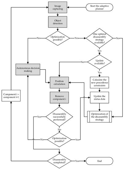
Figure 3.
Concept of the adaptive planner.
Nevertheless, these gaps can be minimized in a disassembly factory after gaining some experience, e.g., by performing several disassembly experiments with autonomous decision-making or by taking advantage of the expertise of disassembly experts gained from past similar batteries. Once these data are available, an optimal disassembly strategy can be determined. In this way, the autonomous disassembly decision can be avoided. The component i to be disassembled is thus specified by the optimizer. After the calculation of the positions, disassembly operations can be performed.
If the disassembly proceeds normally, the disassembly strategy only needs to be calculated once. In case of failure, due to the many uncertainties during the disassembly process, or when complications occur that complicate the execution of disassembly with the existing strategy or pose any safety risks, alternative actions must be initiated. Here, two cases can be distinguished. The first case occurs when there is no optimized disassembly strategy due to incomplete data. In this case, the disassembly task planner must make an additional autonomous decision, such as changing disassembly tools or adjusting the disassembly sequence. The second case occurs if the disassembly strategy optimizer is active. The status data will then be updated if any components were damaged during the disassembly action. This is an important step, since it significantly impacts the optimized disassembly planning, as the appropriate circular economy strategy depends on the component condition. After that, a new disassembly strategy can be calculated to proceed with the disassembly by removing component i. If the disassembly is not yet complete, new images are captured to detect component i + 1 of the computed disassembly strategy. Thereby, it is necessary to check if the previous disassembly step of component i was performed correctly. If any connections were damaged or if the component i was destructively removed, that would require an update of the disassembly strategy. In this case, new precedence constraints may arise that need to be calculated. Moreover, the status data must be updated to calculate the next steps of the disassembly subsequently. In the next section, the design of the disassembly strategy optimizer implemented in this work is addressed.
3.2. Disassembly Optimizer
The first step in the disassembly strategy optimizer is selecting the most suitable optimization method depending on the available data and the objectives of the disassembly (see Figure 4). The technique chosen will then be applied to calculate an optimal disassembly strategy. Disassembly sequence planning (DSP) is a non-deterministic polynomial (NP) problem [25]. Here, the solution space is huge, especially for large products such as EVBs. Furthermore, the solution space becomes larger when further decisions have to be made when planning the disassembly strategy, such as the disassembly depth and the circular economy strategy at the component level. That is why primarily nature-inspired heuristic optimization methods are used in the literature to solve the DSP problem, such as genetic algorithms, particle swarm optimization, ant colony optimization, scatter search, and artificial bee colony optimization [25]. In this work, we will focus on the use of a modified genetic algorithm, since genetic algorithms are the most widely used optimization method for finding optimal disassembly strategies [25]. Furthermore, they offer multiple advantages compared to other metaheuristic methods, such as a wide application range, strong expansibility, and high robustness, since they usually do not fall into local optimal solutions [12]. In addition, genetic algorithms are attractive because, first, they quickly and cost-effectively produce high accuracy solutions, even when the solution space is huge, and second, they are easy to understand and implement since simple mathematics is involved [27].
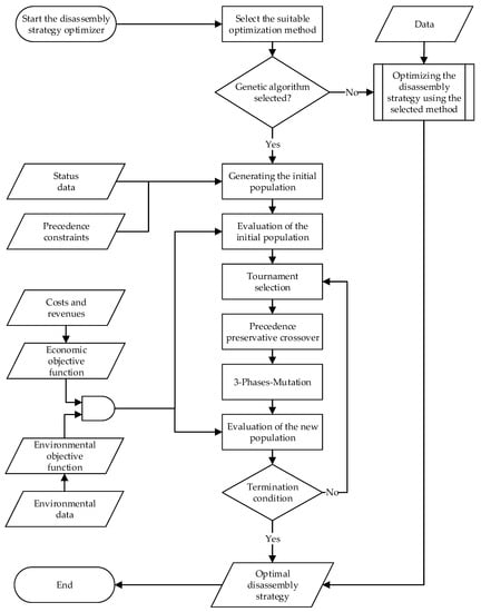
Figure 4.
Disassembly strategy optimizer using a genetic algorithm.
Figure 4 shows the structure of the disassembly strategy optimizer designed in this paper. Here, the steps of the implemented genetic algorithm are shown in detail. It starts with generating the initial population of potential disassembly strategies coded in chromosomes. The chromosome structure will be described in the following subsection. Subsequently, the individuals of the first population are evaluated using an objective function, which can consist of different sub-objectives. In this context, Alfaro-Algaba and Ramirez [14] proposed a combined objective function composed of economic and environmental sub-objectives to maximize the economic profit while minimizing the environmental impact during the disassembly process of EVBs. A lot of data at the component level are needed, such as the disassembly costs, the costs to recondition disassembled components in order to implement a selected circular economy strategy, and environmental data.
Next, the selection step takes place to find out the fittest chromosomes to build a mating pool. The subsequent step is the mutation phase. Here, it should be ensured that all chromosome sections have the opportunity to mutate in order to increase the chances of discovering new solutions with higher performance.
The steps of the genetic algorithm are then performed until a termination condition is satisfied, such as a predefined number of generations or the fulfillment of specified convergence criteria.
In the following subsections, we describe our methodology for the different steps of the implemented genetic algorithm to optimize disassembly strategies for EVBs in terms of the disassembly sequence, disassembly depth, and circular economy strategies at the component level.
3.2.1. Generating the Initial Population
The initial population consists of feasible disassembly strategies coded into chromosomes. Thereby, one chromosome consists of three sections. The first section represents a disassembly sequence, taking into account the precedence constraints. In the second section, all battery components are assigned a circular economy strategy dependent on their condition. The third section consists of only one gene, representing the disassembly depth.
- First chromosome section
A precedence-matrix (P) is used to derive feasible disassembly sequences. It describes the order of precedence of the disassembly steps and can be obtained from carrying out manual disassembly experiments or by using the computer-aided design (CAD) models of the product to be disassembled [28]. Another approach to determining possible precedence relationships in an automatic way based on computer vision was presented in [13]. This can avoid the disadvantages of the two mentioned methods: while manual pre-processing is error-prone and time-consuming, pre-processing using CAD data is often inaccurate. This is because CAD models can rarely still reliably describe the product at their EoL phase, for example, due to corrosion or changes that have been applied to the product during the usage phase. We used the disassembly precedence graph (DPG) to generate the P matrix for the use case in this paper. It allows a simple one-to-one comparison of all components. If a component i is the predecessor of the component j, the value Pij gets the value 1, otherwise 0. The numerical method to derive feasible disassembly sequences from the P matrix is illustrated in Figure 5.
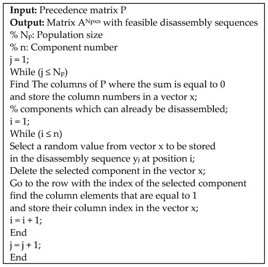
Figure 5.
Method to generate feasible disassembly sequences from a given precedence matrix.
- Second chromosome section
The transfer of battery components into a circular economy takes place via the implementation of circular economy strategies. Here, there are different strategies, which mainly differ in preparing the components and the application field. The waste hierarchy of the European Commission contains five priorities [29]. In this work, we focus on the priorities on the top, as they should be preferred in a circular economy. The highest one is prevention, for example, by extending the life of products through predictive maintenance or simple repair operations. The second priority is repair for reuse, followed by recycling. These priorities can be achieved by applying diverse circularity strategies. Potting et al. [30] identified ten strategies and divided them into three categories: (1) smarter product use and manufacture, (2) extend lifespan of product and its parts, and (3) useful application of materials. Here, we consider only the strategies, which can be applied at the EoL phase. Circularity solutions during the stages of design, manufacturing, and use are ignored. In this scope, the EoL strategies can be reduced to four strategies: reuse, remanufacturing, repurposing, and recycling. The integration of these strategies in the waste hierarchy and the material flows after their application are illustrated in Figure 6. In the literature, different definitions can be found for these strategies [24]. In this paper, we adopt the definitions of Potting et al. [30]. Reuse means the utilization of a discarded battery or a set of its components by another user in the automotive field. Remanufacturing is the treatment of battery parts so that they can at least meet the requirements of newly manufactured products and their utilization for the manufacturing of EVBs. If the battery or its parts are reconditioned and used in another application field, such as stationary energy storage, this is called repurposing. Recycling is the recovery of materials. In this case, pure and high-quality materials for use in the automotive sector should be targeted.
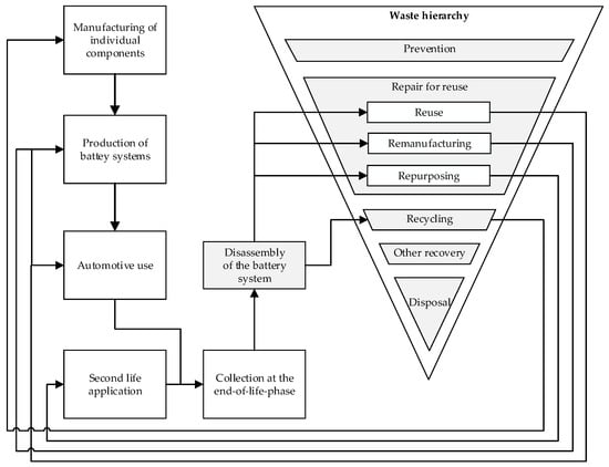
Figure 6.
Overview about the considered end-of-life strategies.
Figure 6 shows that disassembly is of central importance for the implementation of all these circularity strategies. The components of the EVBs can be allocated to different strategies depending on their condition. However, the selection of the optimal circular economy strategy does not depend exclusively on this. Other factors, such as the disassembly costs and the market constraints, such as the potential revenues, also play an important role. Therefore, we consider the selection of the EoL strategy as a part of the disassembly planning. This paper assumes that the feasibility of a circular economy strategy for a given component depends on its condition. That is why the second section of the chromosome must fulfill the condition constraints defined by a condition vector S containing the feasible circular economy strategies CESi for every component i—see Equation (1). Here, the priority of the circular economy strategies is taken into account. If a component i is in excellent condition, it can be allocated to all strategies (reuse, remanufacturing, repurposing, and recycling). In this case, CESi is assigned the value 1. If CESi equals 2, the reuse option will be excluded. Part i can be neither reused nor remanufactured if CESi equals 3. CESi is assigned the value 4 if recycling is the only possible recovery option.
The S vector cannot just be seen as a collection of testing results. Other factors can play a role in determining the potentially possible circular economy strategies for the different battery parts, such as the employees’ experience in the disassembly factory. Testing results include the state of health (SoH) and state of charge (SoC) of battery cells and modules and additional parameters for the rest of the components.
- Third chromosome section
This section consists of a single gene and is used to define the disassembly depth. An EVB could be entirely disassembled by separating all its parts. However, this approach is neither economically nor environmentally practical in an industrial context [16]. Therefore, EVBs are more likely to be subject to incomplete disassembly. Here, there are two methods to perform incomplete disassembly: (1) the selective method and (2) the unrestricted method. The selective method means that specific components are selected to be disassembled. Subsequently, the disassembly planner needs to calculate a strategy for the optimal extraction of these parts. Here, the high-value strategy and the high-impact strategy can be distinguished [31]. For EVBs, the removal of the modules could present a high-value disassembly strategy. The high-impact strategy applies when, for example, a module with safety risks is identified and has to be replaced before reusing the battery. In contrast, no target components are selected in the unrestricted incomplete disassembly. The disassembly planner can freely calculate the optimal disassembly strategy based on an objective function. This method is considered in this paper. Thereby, the gene representing the disassembly depth is randomly generated with values between 0 (no disassembly) and the maximum number of components n while generating the initial population.
In Fehler! Verweisquelle konnte nicht gefunden werden, a disassembly precedence graph of a theoretical product, the associated precedence matrix, and the entire structure of a possible chromosome depending on a given condition vector are presented. In this case, one feasible disassembly sequence is 1-2-3-5-6-4, possible circular economy strategies at the component level are 1-2-4-1-2-4, and the disassembly is complete, since the last gene matches the component number.
3.2.2. Evaluation Method
The performance of the disassembly strategies, coded in chromosomes, has to be evaluated using an objective function, which depends on several parameters. Thereby, different evaluation criteria can be involved, such as the economic and social performance or the environmental impacts. In this paper, we focus on the economic performance of the disassembly strategies by implementing the following objective function to maximize the economic profit (see Equation (2)).
y: Economic profit
i: Index of components
j: Circular economy strategy
DL: Disassembly depth
RVi,j: Revenues from component i while applying the circular economy strategy j
RCi,j: Recovery costs for component i to apply the circular economy strategy j, for example, costs of cleaning, further mechanical treatment, replacement of elements, pyrometallurgical and hydrometallurgical treatment, etc.
OCi,j: Overhead costs for component i to apply the circular economy strategy j
F: Machine and personnel hourly rate for the disassembly process
DTi,j: Disassembly time of component i while applying the circular economy strategy j
q: Value reduction factor for the achievable yield from recycling in case of incomplete disassembly
n: Number of components.
It is assumed that the revenues, recovery costs, and overhead cost depend on the selected circular economy strategy. This also applies to the disassembly times because, in the case of recycling, disassembly operations can be performed faster due to destructive disassembly techniques.
3.2.3. Selection and Crossover
During the selection phase, parents are selected based on their fitness value. The candidates with higher fitness will subsequently mate to produce new generations. In the literature, there are several selection procedures. Ke et al. [12] used the roulette wheel selection method to select the fittest disassembly sequences for EVBs. In this work, a tournament selection technique is used. In a tournament, each chromosome competes twice against two random other chromosomes. The winners move into a mating pool consisting of parents of the same size as the initial population.
Afterward, the crossover phase takes place, usually with high probability (Pc). During this phase, children representing new solutions are generated using the genetic material of two parents. In the context of the disassembly planning task in this paper, it is essential to ensure that the created chromosomes during the crossover phase represent feasible solutions by not violating the precedence relationships and the condition constraints. Therefore, the precedence preservative crossover method described in [27] was chosen and adapted to the characteristics of our chromosome structure. Thereby, two parents generate two children whose chromosome structure is determined by two randomly generated masks. The first child is recombined by using mask 1, and the second one by mask 2. The chromosomes of the children are built up step by step. If the used mask has the value 1 at position i, parent 1 is used to specify the gene i of the child. Here, the leftmost element of parent 1 will be deleted from both parents and placed in the position i of the child. Otherwise, parent 2 is used to define the gene i. Figure 7 shows two possible disassembly sequences of the theoretical product presented in Figure 8, as well as two randomly generated masks, which were used to create new feasible disassembly sequences. The section of the chromosome, representing the circular economy strategies, is recombined simultaneously with the disassembly sequence using the same masks. However, the masks do not play any role in the definition of the disassembly depth. Here, child 1 gets the disassembly depth from parent 1 and child 2 from parent 2.
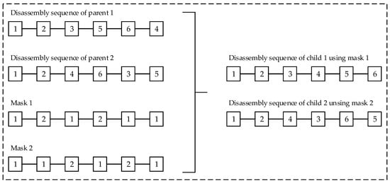
Figure 7.
Using randomly generated masks to produce new feasible disassembly sequences during the crossover phase of the genetic algorithm.
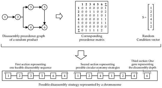
Figure 8.
Structure of the chromosomes of the initial population.
3.2.4. Mutation
The mutation phase plays a crucial role in enhancing the quality of the solution. It increases the diversity in a population and the possibility of discovering new candidates with high performance [27]. In addition, mutation increases the robustness of genetic algorithms concerning local optima [15]. In the context of disassembly planning, the feasibility of mutated solutions must be guaranteed. In this work, the disassembly strategy involves three decisions: the disassembly sequence, the circular economy strategies, and the disassembly depth. Therefore, we chose a three-step mutation by applying the swap mutation method to sections 1 and 2 of the chromosome, representing the disassembly sequence and the circular economy strategies, respectively, and a random resetting of the third chromosome section describing the disassembly depth.
- Step 1: With a mutation probability Pm,1, two randomly selected genes in the first chromosome section are swapped. Thereby, the associated circular economy strategies in the second chromosome section must be swapped in the same manner to ensure the satisfaction of the condition constraints. The mutation is only accepted if the precedence relationships described by the precedence matrix P are not violated.
- Step 2: With a mutation probability Pm,2, two randomly selected genes in the second chromosome section are swapped. The mutation is only accepted if the condition constraints given by the condition vector S are not violated.
- Step 3: With a mutation probability Pm,3, the last gene of the chromosome is reset by randomly adding or subtracting up to 20% of the number of components.
Figure 9 shows an exemplary execution of the three-step mutation based on a disassembly strategy of the theoretical product presented in Figure 7. During the first step, the fifth and last genes of the first section, as well as the corresponding circular economy strategies, were changed. The mutation is accepted because the disassembly sequence 1-2-3-5-4-6 is feasible. The mutation in step 2 is rejected because part 3 cannot be reused (see condition vector S in Figure 7). The mutation during the last step consists of substracting 16.7% of the total number of components (one part).
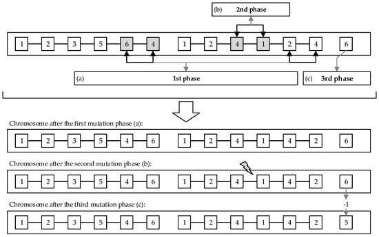
Figure 9.
Three-step mutation in the chromosome sections of the defined theoretical product: (a) step 1: swap mutation in the disassembly sequence and the corresponding circular economy strategies; (b) step 2: swap mutation in the circular economy strategies; (c) step 3: random resetting mutation of the gene representing the disassembly depth DL (DL = DL ± random x; x ∊ [0, 20% ∙ n]; DL ∊ [0, n]; n: number of components).
4. Results and Discussion
4.1. Case Study
The Audi A3 Sportback e-tron hybrid Li-ion battery pack was chosen as the use case in this paper to demonstrate our approach to planning disassembly strategies for battery systems. The selected battery was described in detail by Alfaro-Algaba and Ramirez [14]. The selected disassembly steps are presented, and most of the data required for our proposed disassembly strategy optimization method are available. The relevant assumptions for our use case are listed below:
- Currently, we cannot quantify how diverse disassembly techniques for implementing different circular economy strategies affect disassembly times. Therefore, we assume in the following that the disassembly time per component does not depend on the selected route.
- From interviews with two battery recyclers in Germany, we found out that two workers need 30 min on average to remove the modules manually from a medium-sized battery. This is consistent with the assumption made by Alfaro-Algaba et Ramirez [14]. However, the disassembly times for each component were not given in [14]. In this work, we have estimated the disassembly times for the selected battery based on the experience of Rallo et al. [32] during the disassembly of a similar battery. In Figure 10, the component-specific disassembly times are integrated into the precedence graph of the considered battery. Thereby, disassembly times are coded as follows: x[number of units]; [disassembly time per unit]; [total disassembly time].
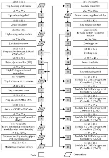 Figure 10. Li-ion battery of the Audi A3 Sportback e-tron hybrid: disassembly precedence graph and disassembly times at the component level. The disassembly times are specified by the following format: x[number of units]; [disassembly time per unit]; [total disassembly time].
 - We only consider a disassembly station with two workers with 100% availability. This means that 3300 units can be disassembled per year (see Table 1).
 Table 1. Throughput of a disassembly station and overhead costs.
 - We used the same overhead costs and their allocation at the component level as in [14]. However, we assume that the overhead costs do not depend on the applied circular economy strategy.
- No components are disposed of. If components are in very poor condition, they must be recycled.
- Processing costs to repurpose the components are assumed to be 25% of the revenues.
- Repurposing revenues are 10% lower than remanufacturing revenues.
- In case of incomplete disassembly, the non-disassembled parts will be recycled. Here, the profit is reduced by 10% due to the missing separation resulting in impure material composition.
- It is assumed that the overhead cost per battery is EUR 96.97 on average (see Table 1). The total overhead costs (OCT) are taken from [14].
- The economic input data and additional assumptions for the cost structure can be found in [14] in order to reproduce the results presented in the next subsection.
In the following, we consider two scenarios for disassembly planning of the considered battery. The upper and lower housing shells and the cooling plates are in poor condition in the first scenario and can, therefore, only be recycled. In the second scenario, they can be assigned to all possible circular economy strategies. The eight modules are in different conditions: two modules must be recycled (CESi = 4), two modules can be reprocessed for second-life applications (CESi = 3), such as stationary energy storage, two modules can be remanufactured for automotive applications (CESi = 2), and the last two modules can be directly reused in the automotive sector with little effort, for example for cleaning and packaging (CESi = 1). In addition, we assume that all connecting elements cannot be reused and consequently have to be recycled in both scenarios. All other components of the considered have the same condition in both scenarios; see the condition vectors of both scenarios in Equations (3) and (4).
4.2. Results
A disassembly strategy in this work consists of three decisions: (1) the optimal disassembly sequence, (2) the optimal circular economy strategy for each component, and (3) the optimal disassembly depth, which represents the stopping point of the disassembly process. These three decisions for both defined scenarios are shown in Figure 11. The used parameters for the initialization of the implemented genetic algorithm are listed Table 2. In the first scenario, the result is an incomplete disassembly with a disassembly depth of 90.63%. We see that the disassembly stops immediately after the modules are removed. In this case, two modules are reused, and two modules are recycled. This represents the best possible route due to the condition constraints. However, the remaining four modules are repurposed, although two modules could be remanufactured. This is because remanufacturing is not economically feasible in our use case. In the first scenario, an economic profit of EUR 553 can be achieved (see Figure 12). In the second scenario, it can be increased by 3.16% to EUR 570.5, although the disassembly costs are higher due to the complete disassembly. This is due to the fact that the upper and lower casing shells, as well as the cooling plates, are reused, and thus higher revenues can be realized. It is worth mentioning here that although the modules are the most valuable components on a battery, other parts contribute in a significant way to increasing the profitability of the disassembly. In the course of our research, we spoke with an EVB recycler in Germany. He said that recycling some EVB variants is particularly attractive because of massive busbars made of copper. Figure 12 shows the evolution of the objective function and the disassembly depth over the 100 generations. Thereby, the algorithm converges after few generations (<20), which means that the optimization can be terminated earlier and thus performed faster.
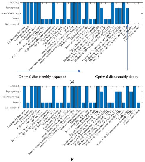
Figure 11.
Optimal disassembly strategies consisting of three decisions (1—optimal disassembly sequence, 2—optimal disassembly depth, and 3—optimal circular economy strategies at the component level): (a) upper and lower housing shells and the cooling plates are in a bad condition and have to be recycled; (b) upper and lower housing shells and the cooling plates are in perfect condition and can be assigned to every circular economy strategy.

Table 2.
Used parameters for the genetic algorithm.
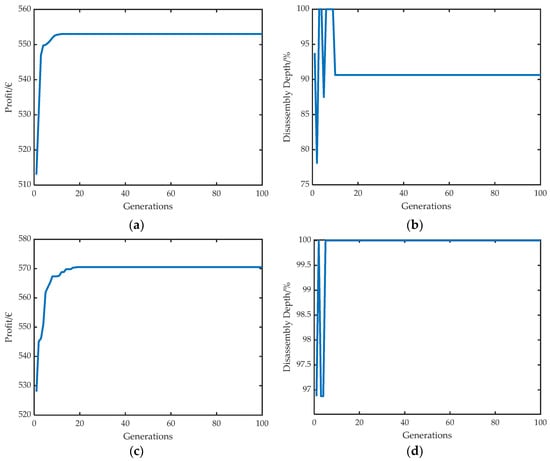
Figure 12.
Model results: (a,b) optimal economic profit and disassembly depth for scenario 1; (c,d) same results for scenario 2.
4.3. Discussion
Optimizing disassembly strategies for EVBs shows a key role in making the circularity of these systems more efficient by targeting higher priorities from the waste hierarchy presented in Figure 6.Here, selecting the optimal circular economy strategies at the component level must be considered as part of the disassembly process planning, since the chosen strategy influences the disassembly techniques and thus the disassembly times and costs.
Disassembly planning and optimization are becoming increasingly complex due to several factors: first, disassembly is subject to many uncertainties, which makes disassembly planning an adaptive and iterative process. Second, disassembly can be performed using different modes (sequential/parallel, complete/incomplete, destructive/non-destructive, automated/manual). Third, on the one hand, disassembly planning is a data-intensive process, and on the other hand, it must be ensured that disassembly is executed even when data are lacking. Fourth, there are multiple variables to optimize the defined objective function, such as the number of tool and direction changes and disassembly times, which depend on other factors such as the joining methods, the disassembly techniques, and the accessibility of the parts. Finally, disassembly strategies do not only consist of a disassembly sequence but also include other decisions, such as the disassembly depth and circular economy strategies for the different components. These three decisions are considered in our proposed adaptive disassembly planner with an integrated disassembly strategy optimizer.
However, in the context of this paper, we only addressed sequential disassembly, since the aim of our current research is to develop an automated disassembly solution for battery packs down to the module level using a robot arm as a single manipulator. Our proposed disassembly strategy optimization method still needs to be extended to the following aspects: (1) including planning methods for cooperative disassembly, which can be applied by using at least two manipulators in fully automated disassembly solutions or by employing a human–machine collaboration, (2) taking into account the tool and direction changes, as they definitely influence the disassembly time, and (3) integrating adaptive methods for updating the condition and precedence constraints in case of complications during the disassembly process or when destructive disassembly steps are used. Furthermore, the adaptive planner should consider further factors, such as the configuration and the availability of the stations. On the one hand, the stations in a disassembly factory may have to be designed differently to be able to disassemble different battery variants and are therefore not suitable for carrying out all disassembly strategies and, on the other hand, a high-capacity utilization should be achieved. This means that EVBs have to be assigned to stations that cannot perform the best possible disassembly strategy in some cases. However, this measure can significantly improve capacity utilization and consequently contribute to establishing highly automated and flexible disassembly factories in the near future, which will become more and more profitable with increasing return volumes. In the literature, there are no concepts for highly flexible disassembly factories for EVBs. In the following publications, we will present several future layouts for disassembly factories under consideration of the presented building blocks of an automated disassembly station in section 0 and show potential challenges for the adaptive disassembly planner with respect to the proposed layouts.
Lastly, optimization of disassembly strategies, often described as disassembly sequence planning (DSP) in several literature sources, should be addressed in the product design phase. This will clearly contribute to achieving fully automated, cost-effective, and environmentally efficient disassembly for battery systems in the automotive sector. In particular, the modules, as the most valuable components in the battery, should be removable after only a few disassembly steps. This is obviously not the case for the battery considered in this paper.
5. Conclusions
An adaptive disassembly planner with an integrated disassembly strategy optimizer for electric vehicle batteries is presented in this paper. It serves to adaptively plan disassembly strategies and optimize them using heuristic optimization algorithms. A disassembly strategy consists of three decisions about the optimal disassembly sequence, disassembly depth, and circular economy strategy for each component. The disassembly strategy optimizer is implemented using a modified genetic algorithm and tested on a selected battery. Thereby, two condition scenarios were considered. In both scenarios, all modules are removed. The disassembly of the remaining components depends on their subsequent route. The presented optimization method is computationally efficient and can be further improved by applying a convergence termination condition. The introduced disassembly planning method can be used at the end-of-life phase to plan the disassembly depending on components’ state and market conditions. Furthermore, our approach is also suitable for use in the begin-of-life stage to ensure the guidelines of “design for disassembly” in the design stage. Nowadays, there is a need for action in both application cases because, first, disassembly processes are mainly carried out based on experience, and second, battery treatment at the end-of-life phase is hardly considered when designing these systems.
Author Contributions
Conceptualization, S.B.; methodology, S.B.; software, S.B. and F.P.R.; writing—original draft preparation, S.B.; writing—review and editing, M.W., K.P.B. and F.P.R.; visualization, S.B.; project administration, M.W.; funding acquisition, M.W. and K.P.B. All authors have read and agreed to the published version of the manuscript.
Funding
The authors wish to thank the Ministry of the Environment, Climate Protection and the Energy Sector Baden-Wuerttemberg for funding this work under the funding code L7520101 as part of the accompanying research of the project “DeMoBat”. The financial support is gratefully acknowledged.
Institutional Review Board Statement
Not applicable.
Informed Consent Statement
Not applicable.
Data Availability Statement
The data presented in this study are available within the article.
Conflicts of Interest
The authors declare no conflict of interest.
References
- Acatech/Circular Economy Initiative Deutschland/SYSTEMIQ. Ressource-Efficient Battery Life Cycles: Driving Electric Mobility with the Circular Economy. 2020. Available online: https://www.acatech.de/publikation/ressourcenschonende-batteriekreislaeufe/ (accessed on 14 July 2021).
- Helms, H.; Kämper, C.; Biemann, K.; Lambrecht, U.; Jöhrens, J.; Meyer, K. Klimabilanz Von Elektroautos: Einflussfaktoren Und Verbesserungspotenzial. 2019. Available online: https://www.agora-verkehrswende.de/fileadmin/Projekte/2018/Klimabilanz_von_Elektroautos/Agora-Verkehrswende_22_Klimabilanz-von-Elektroautos_WEB.pdf (accessed on 14 July 2021).
- Karabelli, D.; Kiemel, S.; Singh, S.; Koller, J.; Ehrenberger, S.; Miehe, R.; Weeber, M.; Birke, K.P. Tackling xEV Battery Chemistry in View of Raw Material Supply Shortfalls. Front. Energy Res. 2020, 8, 331. [Google Scholar] [CrossRef]
- Sato, F.E.K.; Nakata, T. Recoverability Analysis of Critical Materials from Electric Vehicle Lithium-Ion Batteries through a Dynamic Fleet-Based Approach for Japan. Sustainability 2020, 12, 147. [Google Scholar] [CrossRef] [Green Version]
- Kotak, Y.; Marchante Fernández, C.; Canals Casals, L.; Kotak, B.S.; Koch, D.; Geisbauer, C.; Trilla, L.; Gómez-Núñez, A.; Schweiger, H.-G. End of Electric Vehicle Batteries: Reuse vs. Recycle. Energies 2021, 14, 2217. [Google Scholar] [CrossRef]
- Glöser-Chahoud, S.; Huster, S.; Rosenberg, S.; Baazouzi, S.; Kiemel, S.; Singh, S.; Schneider, C.; Weeber, M.; Miehe, R.; Schultmann, F. Industrial disassembling as a key enabler of circular economy solutions for obsolete electric vehicle battery systems. Resour. Conserv. Recycl. 2021, 174, 105735. [Google Scholar] [CrossRef]
- Yun, L.; Linh, D.; Shui, L.; Peng, X.; Garg, A.; Le, M.L.P.; Asghari, S.; Sandoval, J. Metallurgical and mechanical methods for recycling of lithium-ion battery pack for electric vehicles. Resour. Conserv. Recycl. 2018, 136, 198–208. [Google Scholar] [CrossRef]
- Elwert, T.; Römer, F.; Schneider, K.; Hua, Q.; Buchert, M. Recycling of Batteries from Electric Vehicles. In Behaviour of Lithium-Ion Batteries in Electric Vehicles; Pistoia, G., Liaw, B., Eds.; Springer International Publishing: Cham, Switzerland, 2018; pp. 289–321. ISBN 978-3-319-69949-3. [Google Scholar]
- Tan, W.J.; Chin, C.M.M.; Garg, A.; Gao, L. A hybrid disassembly framework for disassembly of electric vehicle batteries. Int. J. Energy Res. 2021, 45, 8073–8082. [Google Scholar] [CrossRef]
- Gerlitz, E.; Greifenstein, M.; Hofmann, J.; Fleischer, J. Analysis of the Variety of Lithium-Ion Battery Modules and the Challenges for an Agile Automated Disassembly System. Procedia CIRP 2021, 96, 175–180. [Google Scholar] [CrossRef]
- Schwarz, T.E.; Rübenbauer, W.; Rutrecht, B.; Pomberger, R. Forecasting Real Disassembly Time of Industrial Batteries Based on Virtual MTM-UAS Data. Procedia CIRP 2018, 69, 927–931. [Google Scholar] [CrossRef]
- Ke, Q.; Zhang, P.; Zhang, L.; Song, S. Electric Vehicle Battery Disassembly Sequence Planning Based on Frame-Subgroup Structure Combined with Genetic Algorithm. Front. Mech. Eng. 2020, 6. [Google Scholar] [CrossRef]
- Choux, M.; Marti Bigorra, E.; Tyapin, I. Task Planner for Robotic Disassembly of Electric Vehicle Battery Pack. Metals 2021, 11, 387. [Google Scholar] [CrossRef]
- Alfaro-Algaba, M.; Ramirez, F.J. Techno-economic and environmental disassembly planning of lithium-ion electric vehicle battery packs for remanufacturing. Resour. Conserv. Recycl. 2020, 154, 104461. [Google Scholar] [CrossRef]
- Ren, Y.; Zhang, C.; Zhao, F.; Xiao, H.; Tian, G. An asynchronous parallel disassembly planning based on genetic algorithm. Eur. J. Oper. Res. 2018, 269, 647–660. [Google Scholar] [CrossRef]
- Wegener, K.; Andrew, S.; Raatz, A.; Dröder, K.; Herrmann, C. Disassembly of Electric Vehicle Batteries Using the Example of the Audi Q5 Hybrid System. Procedia CIRP 2014, 23, 155–160. [Google Scholar] [CrossRef] [Green Version]
- Schäfer, J.; Singer, R.; Hofmann, J.; Fleischer, J. Challenges and Solutions of Automated Disassembly and Condition-Based Remanufacturing of Lithium-Ion Battery Modules for a Circular Economy. Procedia Manuf. 2020, 43, 614–619. [Google Scholar] [CrossRef]
- Leitz, A. Laserstrahlschweißen Von Kupfer-Und Aluminiumwerkstoffen in Mischverbindung; Herbert Utz Verlag Wissenschaft: München, Germany, 2016; ISBN 978-3-8316-4549-7. [Google Scholar]
- Kay, I.; Esmaeeli, R.; Hashemi, S.R.; Mahajan, A.; Farhad, S. Recycling Li-Ion batteries: Robotic disassembly of electric vehicle battery systems. In Proceedings of the International Mechanical Engineering Congress and Exposition (ASME 2019), Salt Lake City, UT, USA, 11–14 November 2019; Volume 6, p. 11112019, ISBN 978-0-7918-5943-8. [Google Scholar]
- Li, L.; Zheng, P.; Yang, T.; Sturges, R.; Ellis, M.W.; Li, Z. Disassembly Automation for Recycling End-of-Life Lithium-Ion Pouch Cells. JOM 2019, 71, 4457–4464. [Google Scholar] [CrossRef] [Green Version]
- Vongbunyong, S.; Chen, W.H. Disassembly Automation; Springer International Publishing: Cham, Switzerland, 2015; ISBN 978-3-319-15182-3. [Google Scholar]
- Schmitt, J.; Haupt, H.; Kurrat, M.; Raatz, A. Disassembly automation for lithium-ion battery systems using a flexible gripper. In Proceedings of the 15th International Conference on Advanced Robotics (ICAR 2011), Tallinn, Estonia, 20–23 June 2011; pp. 291–297, ISBN 978-1-4577-1159-6. [Google Scholar]
- Herrmann, C.; Raatz, A.; Andrew, S.; Schmitt, J. Scenario-Based Development of Disassembly Systems for Automotive Lithium Ion Battery Systems. AMR 2014, 907, 391–401. [Google Scholar] [CrossRef]
- Kiemel, S.; Koller, J.; Kaus, D.; Singh, S.; Full, J.; Weeber, M.; Miehe, R.; Ehrenberger, S.; Österle, I.; Senzeybek, M.; et al. Untersuchung: Kreislaufstrategien für Batteriesysteme in Baden-Württemberg: KSBS BW, Stuttgart. 2020. Available online: https://www.ipa.fraunhofer.de/content/dam/ipa/de/documents/Kompetenzen/Nachhaltige-Produktion-und-Qualitaet/Endbericht_KSBS_offen.pdf (accessed on 16 November 2020).
- Zhou, Z.; Liu, J.; Pham, D.T.; Xu, W.; Ramirez, F.J.; Ji, C.; Liu, Q. Disassembly sequence planning: Recent developments and future trends. Proc. Inst. Mech. Eng. Part B J. Eng. Manuf. 2019, 233, 1450–1471. [Google Scholar] [CrossRef]
- Ren, Y.; Jin, H.; Zhao, F.; Qu, T.; Meng, L.; Zhang, C.; Zhang, B.; Wang, G.; Sutherland, J.W. A Multiobjective Disassembly Planning for Value Recovery and Energy Conservation From End-of-Life Products. IEEE Trans. Automat. Sci. Eng. 2021, 18, 791–803. [Google Scholar] [CrossRef]
- Kheder, M.; Trigui, M.; Aifaoui, N. Disassembly sequence planning based on a genetic algorithm. Proc. Inst. Mech. Eng. Part C J. Mech. Eng. Sci. 2015, 229, 2281–2290. [Google Scholar] [CrossRef]
- Zhou, Z.; Liu, J.; Pham, D. Disassembly Sequence Planning: Recent Developments and Future Trends. 2018. Available online: https://journals.sagepub.com/doi/full/10.1177/0954405418789975 (accessed on 1 May 2021).
- Hernández Parrodi, J.C.; Höllen, D.; Pomberger, R. Potential and main technological challenges for material and energy recovery from fine fractions of landfill mining: A critical review. Detritus 2018, 3, 19–29. [Google Scholar] [CrossRef]
- José, P.; Marko, H.; Ernst, W.; Aldert, H. Circular Economy: Measuring Innovation in the Product Chain; Policy Report. 2017. Available online: https://www.pbl.nl/sites/default/files/downloads/pbl-2016-circular-economy-measuring-innovation-in-product-chains-2544.pdf (accessed on 1 May 2021).
- Ren, Y.; Tian, G.; Zhao, F.; Yu, D.; Zhang, C. Selective cooperative disassembly planning based on multi-objective discrete artificial bee colony algorithm. Eng. Appl. Artif. Intell. 2017, 64, 415–431. [Google Scholar] [CrossRef]
- Rallo, H.; Benveniste, G.; Gestoso, I.; Amante, B. Economic analysis of the disassembling activities to the reuse of electric vehicles Li-ion batteries. Resour. Conserv. Recycl. 2020, 159, 104785. [Google Scholar] [CrossRef]
Publisher’s Note: MDPI stays neutral with regard to jurisdictional claims in published maps and institutional affiliations. |
© 2021 by the authors. Licensee MDPI, Basel, Switzerland. This article is an open access article distributed under the terms and conditions of the Creative Commons Attribution (CC BY) license (https://creativecommons.org/licenses/by/4.0/).