Article

High-Performance Amorphous Carbon Coated LiNi0.6Mn0.2Co0.2O2 Cathode Material with Improved Capacity Retention for Lithium-Ion Batteries

1
Center for Low-Emission Transport, AIT Austrian Institute of Technology GmbH, Giefinggasse 2, 1210 Vienna, Austria
2
Department of Electrical Engineering and Energy Technology (ETEC), Vrije Universiteit Brussel, 1050 Brussels, Belgium
3
Sustainable Thermal Energy Systems, AIT Austrian Institute of Technology GmbH, Giefinggasse 2, 1210 Vienna, Austria
4
Department of Electrochemical and Surface Engineering (SURF), Vrije Universiteit Brussel, 1050 Brussels, Belgium
*
Authors to whom correspondence should be addressed.
Batteries 2021, 7(4), 69; https://doi.org/10.3390/batteries7040069
Submission received: 18 August 2021 / Revised: 8 October 2021 / Accepted: 18 October 2021 / Published: 26 October 2021

Abstract

:
Coating conducting polymers onto active cathode materials has been proven to mitigate issues at high current densities stemming from the limited conducting abilities of the metal-oxides. In the present study, a carbon coating was applied onto nickel-rich NMC622 via polymerisation of furfuryl alcohol, followed by calcination, for the first time. The formation of a uniform amorphous carbon layer was observed with scanning- and transmission-electron microscopy (SEM and TEM) and X-ray photoelectron spectroscopy (XPS). The stability of the coated active material was confirmed and the electrochemical behaviour as well as the cycling stability was evaluated. The impact of the heat treatment on the electrochemical performance was studied systematically and was shown to improve cycling and high current performance alike. In-depth investigations of polymer coated samples show that the improved performance can be correlated with the calcination temperatures. In particular, a heat treatment at 400 °C leads to enhanced reversibility and capacity retention even after 400 cycles. At 10C, the discharge capacity for carbon coated NMC increases by nearly 50% compared to uncoated samples. This study clearly shows for the first time the synergetic effects of a furfuryl polymer coating and subsequent calcination leading to improved electrochemical performance of nickel-rich NMC622.

Graphical Abstract

1. Introduction

Ni-rich NMC, LiNixMnyCozO2 (where x ≥ 0.5, x + y + z = 1) has attracted great attention in the battery community due to a combination of high reversible capacity (180–250 mAh g−1) and high operating voltage (~3.8 V vs. Li+/Li) that stems from two-dimensional lithium-ion diffusion and good lithium-ion conductivity [1]. However, in spite of these advantages, the material is known to possess problems such as surface side reactions and chemical instability at the highly de-lithiated stages (>4.3 V vs. Li+/Li) [2,3,4,5]. To overcome these issues and to achieve the long-term performance of Ni-rich NMC materials, surface stabilisation of Ni-rich materials is considered an efficient strategy [3,4,5,6,7,8,9]. Such surface coating of materials/layers should offer decreased surface impedance, unchanged Li+ diffusivity, and chemical stability vs. the electrolyte throughout the applied voltage window. Metal oxides, including Al2O3 [10,11,12], ZrO2 [13,14], MgO [15], Li2O–2B2O3 [16], TiO2 [17], SiOx [18], ZnO [19], SnO2 [20], Y2O3 [21], LiNbO3 [22], and LiAlPO3.93F1.07 [23] have been employed as coatings which improved the electrochemical performance and stabilised Ni-rich NMC materials during prolonged cycling. The delay in structural degradation stems from an effective protective layer that prevents the material from HF-based surface side reactions and lowers the charge transfer resistance of Li+ and transition metals dissolution. However, their inherently low electronic conductivity results in a poor electrochemical performance at high current rates, which challenges their ability in high power applications [24,25,26,27]. To solve this problem, a carbon coating on the surface of metal-oxide particles is one of the strategies demonstrated in the literature. Many studies demonstrated that a nanometre layer of carbon increased electronic conductivity of the cathode material and reduced side reactions with the electrolytes. The layer creates a physical barrier between the electrolyte and the metal-oxide-based cathodes [24]. This has been widely applied for low conducting materials such as LiFePO4 [28,29] and Li2FeSiO4 [30,31]. Hence, thin layers of carbons are a proven strategy to increase the electrochemical performance at high current rates. However, achieving homogeneous coatings on micrometre-sized commercial NMC cathode materials remains challenging. In this regard, amorphous carbon-based materials from polymerisation offer homogeneous coverage and high electronic conductivity. Their good chemical and electrochemical stability have been reported as promising alternatives to metal-oxide-based coatings [32]. Moreover, low material cost and processes makes them potentially competitive with metal-oxide coatings. Compared to nanosized materials, large particles of a mean diameter of ~10 µm were found difficult to coat and only a thin layer on the material can be obtained through a general solution-based coating approach. Furthermore, it is well known that in inert atmosphere carbon acts as a reducing agent and can remove oxygen from the NMC structure, leading to the formation of unwanted surface species and material degradation [33]. Therefore, in this work we present a method that reduces the risk of oxidizing the carbon layer by a process that involves polymer curing on NMC particles, and the formation of carbon at elevated temperatures is carried out in air atmosphere. Here, we have performed an amorphous polymer coating of poly-furfuryl on NMC622 through the polycondensation of furfuryl alcohol (Equation (1)). In detail, the process contains the steps of monomerpolymerisation at 80 °C, followed by curing of the polymerised products at 120 °C to form a cross-linked polymer structure. A final calcination step creates a uniform amorphous carbon layer.
Although there are approaches to obtain carbon coated Ni-rich NMC through solid state methods, these examples restrict control over thickness [24,34]. On the other hand, polymerisation of organic monomers on top of metal-oxide particles followed by calcination allows for the formation of amorphous carbon with a defined thickness. Hence, in the present study we performed carbon coatings on NMC622 micro-sized particles through the polymerisation of furfuryl alcohol (FA) followed by a calcination step. A systematic study of carbon coating thickness and heat treatment on NMC622, comparing coated with uncoated micro particles that improve the electrochemical performance, is presented in this work. Furfuryl alcohol is used as fire retardant and for its thermosetting properties after polymerisation [35] as well as its ability to form carbon layers with good mechanical properties. It is also known to be chemical inert towards corrosive species, such as HF [36]. Here, we show that a uniform coating was achieved by polycondensation of furfuryl alcohol followed by calcination of the cross-linked polymer structure in air. Further, a detailed study on the effect of variation of calcination temperature of the poly-furfuryl coated NMC622 on the thickness of carbon coating was performed and revealed optimum conditions at 400 °C. A nearly 15 nm thick layer of amorphous carbon on NMC622 particles can be derived from the calcination of poly-furfuryl, which results in increased capacity retention and higher discharge capacity of up to 10 C during discharge.

2. Results

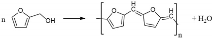
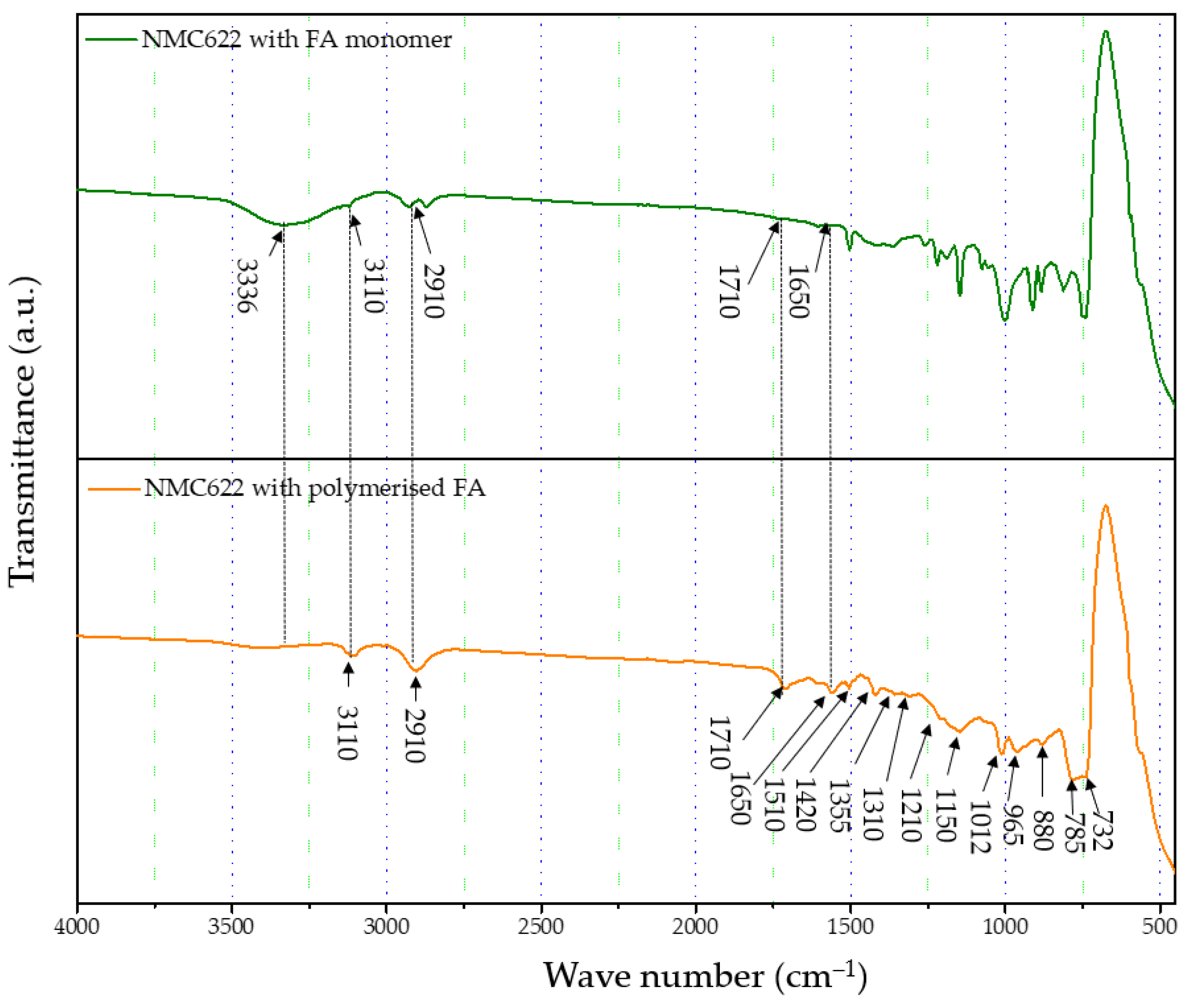
2.1. Polymer Formation

The formation and curing of the polymer were confirmed by the Fourier-transform infrared spectroscopy (FTIR) analysis shown in Figure 1. The broad OH peak in the region 3600–3000 cm−1 is strongly reduced, indicating that polycondensation of the monomer took place. Moreover, increased vibration bands in the spectral range of 1710 and 1520 cm−1 indicate the presence of C=O and C=C stretching, respectively, which implies the successful formation of cross-linkage via the Diels–Alder reaction followed by ring opening. These functionalities, on the other hand, cannot be detected in the furfuryl alcohol monomer [37].
Polycondensation reaction
Batteries 07 00069 i001

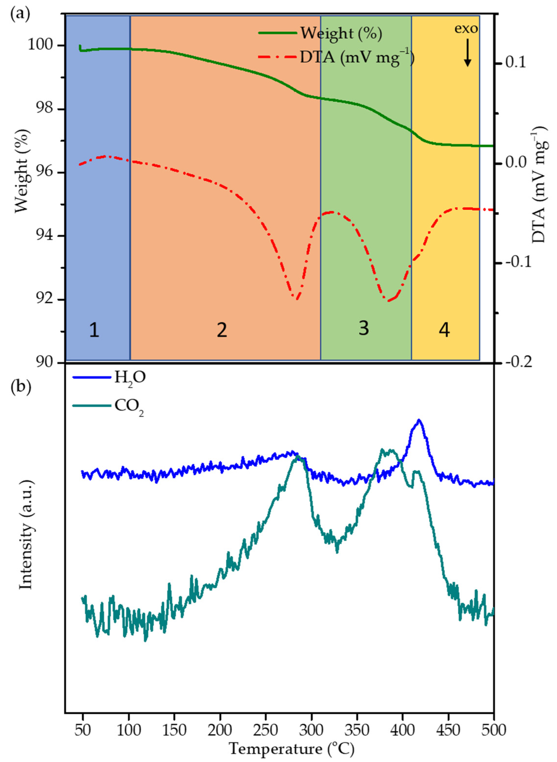
2.2. Thermal Decomposition of the FA Polymer

The thermal decomposition of the cured polymer coating on top of NMC622 was investigated by thermogravimetric analysis/ differential thermal analysis (TGA/DTA) and mass spectrometry. NMC coated with cured FA-polymer was loaded in a corundum crucible and subjected to thermal analysis. The sample was heated from room temperature up to 500 °C with a heating rate of 5 °C/min. Weight loss and differential temperature was recorded, and the evolved gases were analysed. A weight loss of ~3% between room temperature and 410 °C can be divided into four regions (30–100 °C, 100–310 °C, 310–410 °C, 410–480 °C) as shown in Figure 2a. In region 1a, weight loss of ∼0.42 wt.% in the temperature range of 30–100 °C is observed and can be attributed to the desorption of residual water stemming from the polycondensation reaction and humidity. Such low quantities are below the detection limit of the mass spectrometer and are therefore not visible. In region 2 and 3, the weight loss of ~2.6 wt.% between ~100 and 410 °C can mainly be assigned to the decomposition of the polymer coating and formation of a carbon species as the function of the temperature; above 410 °C, weight loss becomes insignificant. Therefore, 400 °C was chosen as the optimum temperature with the objective to obtain a thin-layer carbon coating on top of NMC622 particles. The DTA curve shows two exothermic peaks during the heating process; to understand the mechanism behind the decomposition, TGA/DTA coupled mass spectrometry was carried out with the mass to charge ratios m/z of 18 and 44 datapoints corresponding to H2O and CO2, respectively (Figure 2). Between 30 and 100 °C, region 1 shows an endothermic peak which is characteristic for the evaporation of water. In contrast to region 1, region 2 (100–310 °C) is characterised by an exothermic peak together with the evolution of water and CO2. In the literature it is well described that the rupture of furan rings leads to the formation of amorphous carbon species and subsequent evolution of CO2 [38], which indicates the decomposition of the organic polymer structure. The appearance of H2O at an onset temperature of 250 °C can be explained as the remaining monomer undergoing a polycondensation reaction. In region 3, a second exothermic process starts at 330 °C which finds its maximum at 390 °C. The appearance of only CO2 correlates to further decomposition of the carbon-based structure.

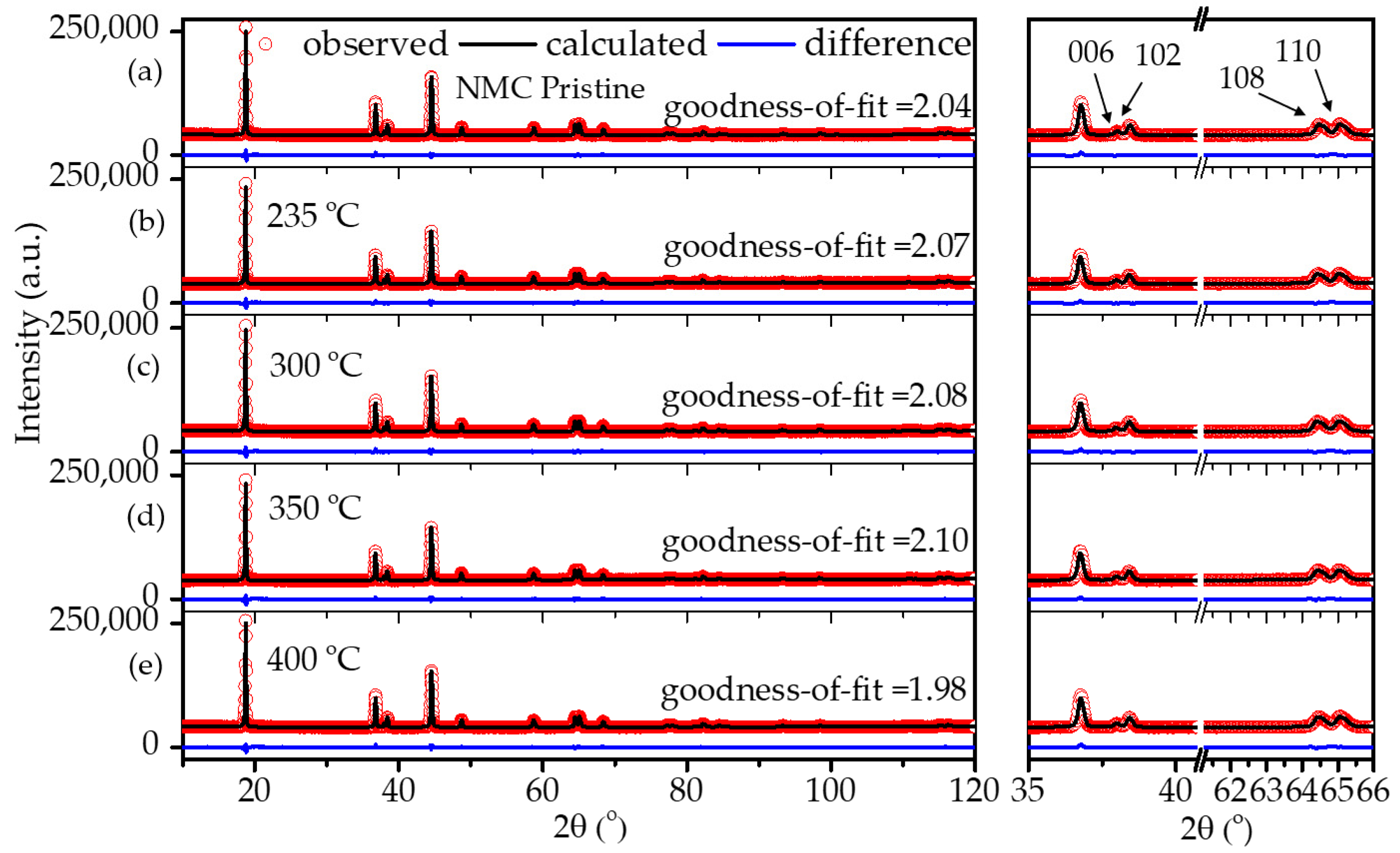
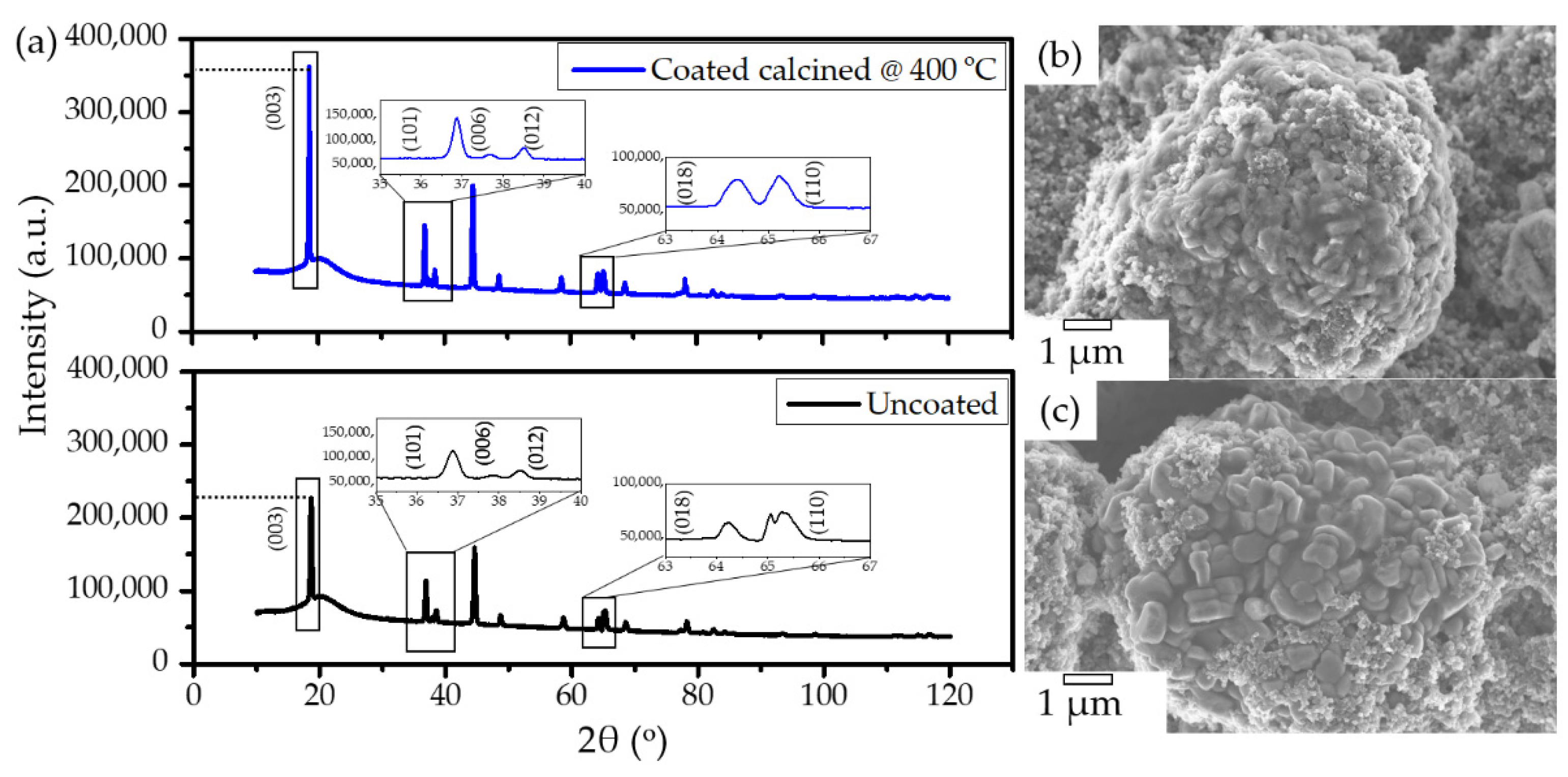
2.3. Structural Stability of Coated NMC622

It is well known that carbon is a reducing agent and thus can reduce the transitional metal in the NMC structure, leading to oxygen release in the structure and the formation of CO/CO2 gases [8,33]. Hence, layered NMC has the tendency to transform to spinels and rock-salt structures upon heating in the presence of carbon [33]. Therefore, considerable efforts have been devoted during the calcination process to obtain carbon from polymeric organic materials in an air atmosphere while maintaining the layered NMC structure. In order to verify the structural stability of the NMC622 upon systematic heating, a study on the calcination of the poly-furfuryl coated particles was carried out at 235 °C, 300 °C, 350 °C, and 400 °C as shown in Figure 3. To investigate changes in the polymer structure where initiation of decomposition was expected, 235 °C was chosen as the lowest temperature and the upper limit was set at 400 °C since the mass loss at higher temperatures appeared insignificant. Powder X-ray diffraction at elevated temperatures revealed that all materials remained single phase NMC622 in the R-3m space group [1]. Clear peak splitting at ~38° and ~65° 2θ corresponds to (006)/(102) and (108)/(110) hkl planes and proves the high crystallinity of the materials after coating and heating. Lattice parameters obtained from Rietveld refinement are given in Table 1. It has been reported that the intensity ratio of (003)/(104) indicates cation mixing in the lattice of NMC622 material, and that values of (003)/(104) > 1.2 indicate no obvious cation mixing in the structure [1,39,40], as was found for the coated materials described here (Table 1). Also, the c/a ratio of >4.91 strongly indicates hexagonal ordering of the coated materials and the exclusion of cation-mixing [39]; this further proves the thermal stability and remaining crystal integrity of NMC622 throughout the polymerisation process and subsequent heat treatments.

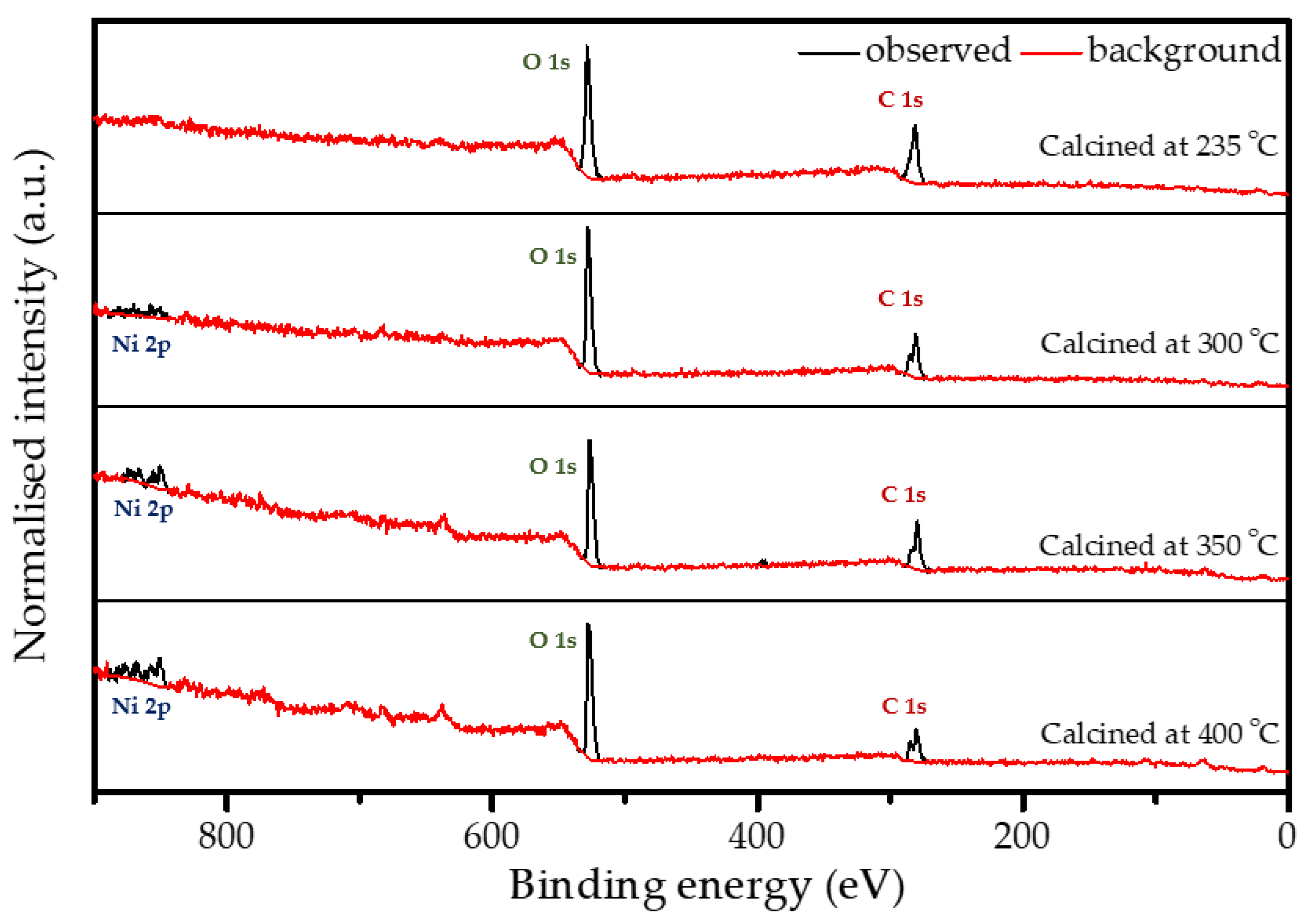
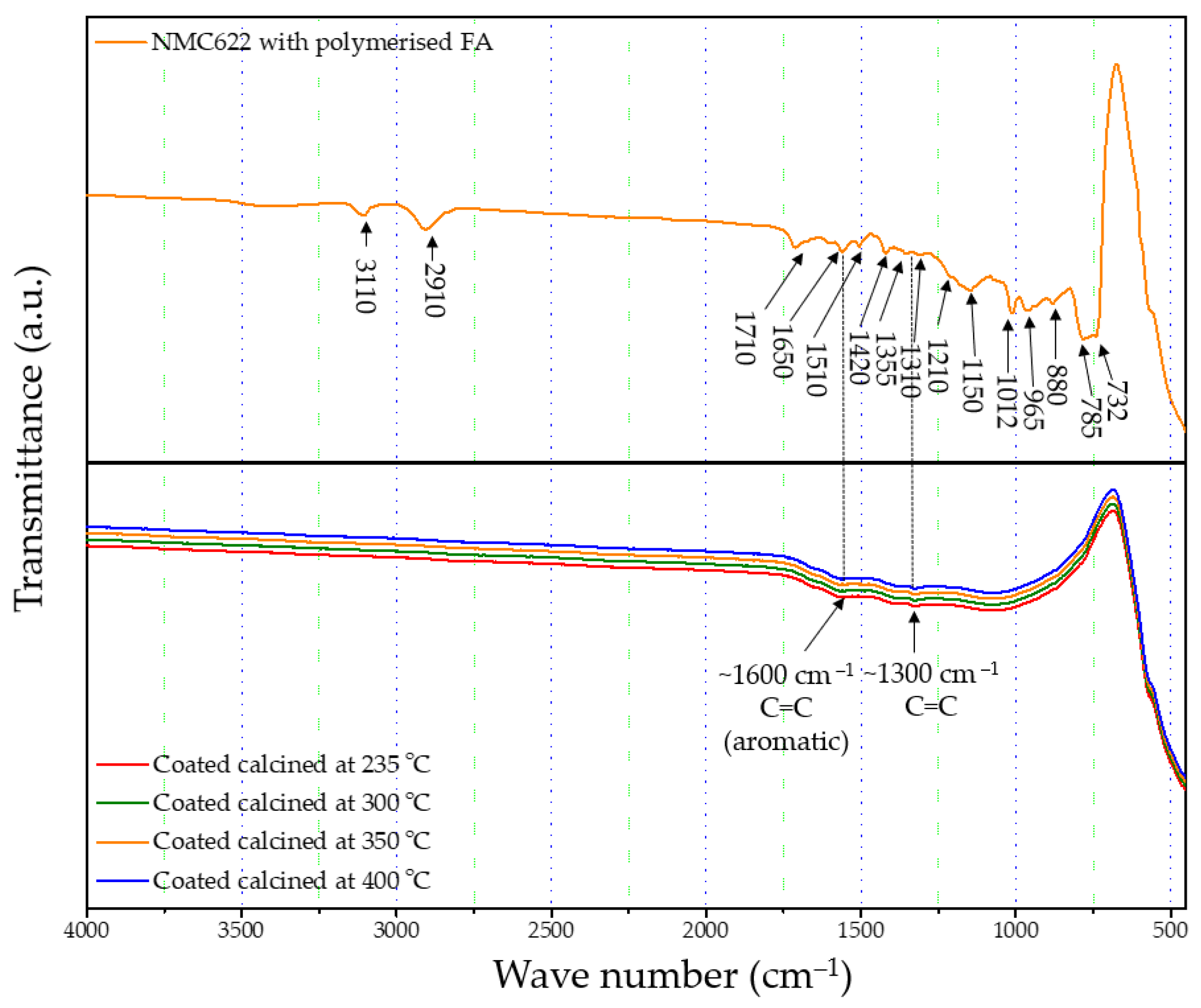
2.4. Structure of the Polymer Coating

FTIR-ATR analysis of the uncoated pristine NMC showed weak bands between 400 and 520 cm−1 corresponding to the O–M–O asymmetric bending modes, and above 520 cm−1 asymmetric stretching modes of the MO6 (where, M=Ni, Co, Mn) octahedra (Figure 1) [41,42]. The main characteristic bands for the cured polymer coated on NMC622 were seen at 3110 cm−1 (–CH in aromatic rings), 2910 cm−1 (aliphatic –CH stretch), 1710 cm−1 (C=O stretch), 1650 cm−1 (C=C stretch), 1510 cm−1 (ring vibrations), 1420 cm−1 (asymmetric –CH2 bending), 1355 cm−1 (–CH ring stretch), 1210 cm−1, 1150 cm−1 (C–C furan stretch), 1012 cm−1 (=C–O–C= furan ring stretch), 880 cm−1 (=C–H= furan ring stretch), 785 cm−1 (twisting of –CH ring structure), and 732 cm−1 (–CH ring out of plane stretch) [43]. However, all vibrations in the range of 1675–1015 cm−1 disappear after the calcination process and the band corresponding to the carbonyl species at 1715 cm−1 decreases in intensity. At the same time, two main broader bands increase at ~1600 and ~1300 cm−1 (Figure 4), which are described in the literature as the formation of amorphous carbon and carbon nanotubes [44,45]. Only weak intensity bands can be observed in Figure 4, which were caused by the low quantity of the amorphous carbon due to the thin nature of the coating remaining on the samples after the heat treatment. These absorption bands show proof of the conversion from the poly-furfuryl alcohol polymer into an amorphous carbon-like structure with an aromatic character [46]. Based on these findings, the successful transformation of the poly-furfuryl into the carbon structure can be confirmed.
X-ray photoelectron spectroscopy (XPS) analysis was performed on all calcined samples to confirm the presence of carbon species and to determine the variation in elemental composition of the surface layer throughout the calcination process. Figure 5 shows the full XPS survey spectra of all the coated and calcined powder samples, which contain the expected elements C and O on all samples, as well as Ni. However, the sample heated to 235 °C does not show a significant peak for nickel (see also Figure S2b), which can be explained by changes in coating thickness with increasing calcination temperature together with the limited depth sensitivity of the instrument of about 7–10 nm. When increasing the calcination temperature, the carbon content decreases, while O and Ni increase as shown in Figure S2b and Table 2, which points towards the removal of the carbon layer. An anomaly is observed at 350 °C due to the partial surface charging during the measurements, even though it was minimised, but not fully suppressed by using a low energy electron flood gun for charge compensation. The C1s spectrum shown in Figure S2a consists of two peaks. The high intensity peak at 285.0 eV is attributed to the amorphous carbon [36] present in the sample, whereas a low intensity peak at 289.2 eV originates from carboxylic groups [47]. The resulting amorphous carbon derived from poly-furfuryl alcohol is known for its excellent combination of mechanical and optical properties, i.e., extreme hardness and inertness against acid environment (HF included) [36,48]. Results from FTIR analysis and XPS measurement confirms a thin layer of carbon and the amorphous nature of the structure obtained from the calcination process of poly-furfuryl.

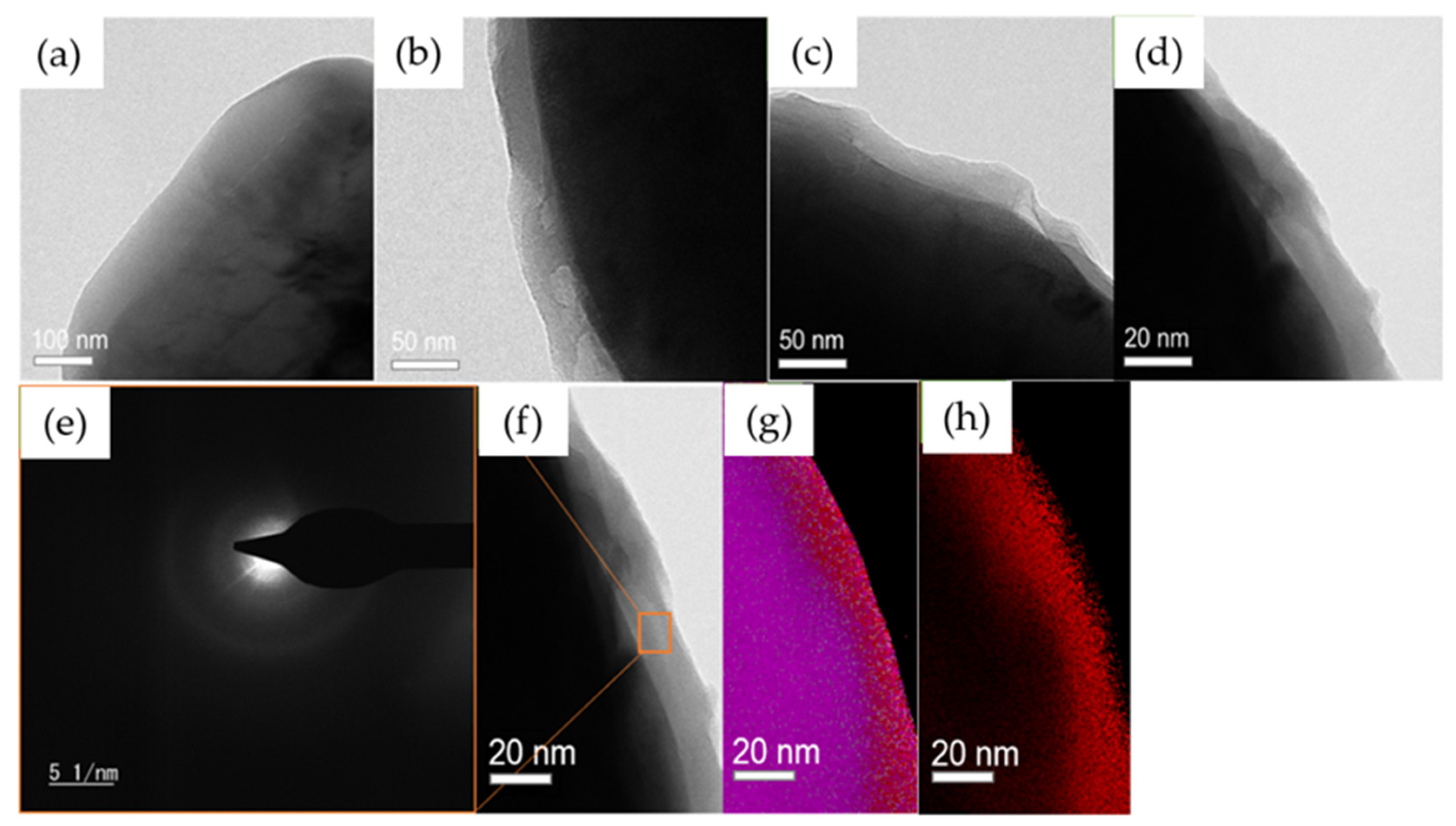
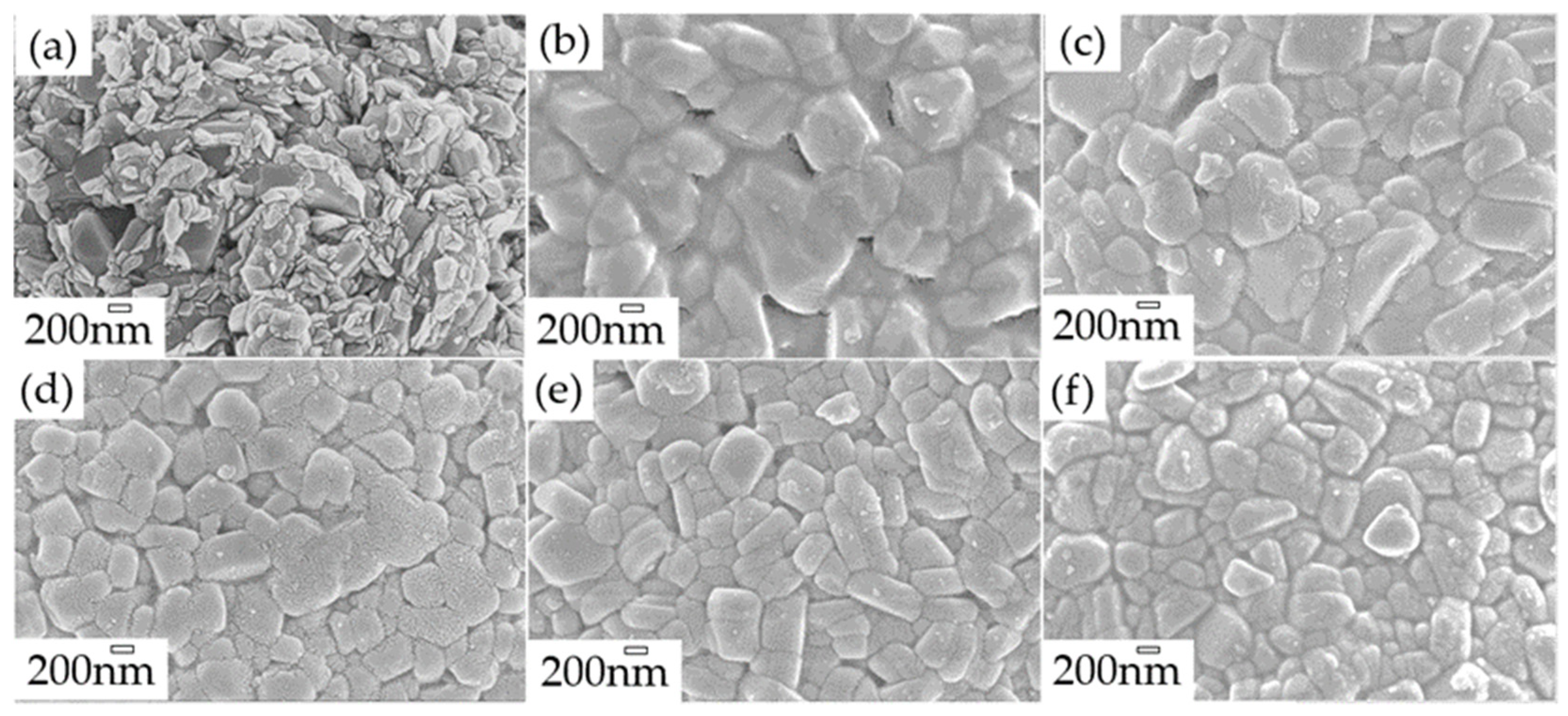
2.5. Morphology of the Polymer Coating

The morphology and microstructure of uncoated pristine, coated, and calcined powders were investigated by scanning electron microscopy (SEM) and transmission electron microscopy (TEM) analysis. SEM of the uncoated pristine sample (Figure 6a) shows 200–500 nm primary NMC622 particles with rough surfaces, and secondary spherical particles of 5–15 µm size. Figure 6b shows a complete coverage of the NMC particles with the polymer. Furthermore, calcination of the polymer structure (Figure 6c–f) led to a homogeneous carbon coated NMC622 material, as can also be observed via elemental mapping with energy dispersive X-ray spectroscopy (EDX). The results of the detailed EDX analysis (see Figure S3) show the loss of carbon for the coated sample as the calcination temperature increases. CHN analysis was carried out to determine the amount of carbon derived from poly-furfuryl calcination (Table 3); it shows that an increase in temperature results in the decrease of carbon content. The findings are in line with TGA data, which show a mass loss with increasing temperature.
TEM was carried out to examine the thickness of the coating after each temperature calcination and confirms a uniform layer of carbon around the surface of the NMC secondary particles (Figure 7). It clearly shows the effect of temperature on the polymer layer thickness. We observed a~100 nm thickness for samples calcined at 235 °C, ~50 nm at 300 °C, ~30 nm at 350 °C, and ~15–20 nm at 400 °C. Furthermore, a uniform carbon layer was observed by surface mapping; the results are presented in Figure 7f–h. The images provide a clear picture of a homogeneous carbon coating on top of the NMC particles. However, the diffused ring in the coated area indicates the amorphous nature of the carbon (Figure 7e) [49]. These findings are in line with the XPS, EDX, and CHN analyses, which depict a strong dependency of coating thickness to the calcination temperature resulting in uniform carbon layers.

2.6. Electrochemical Performance

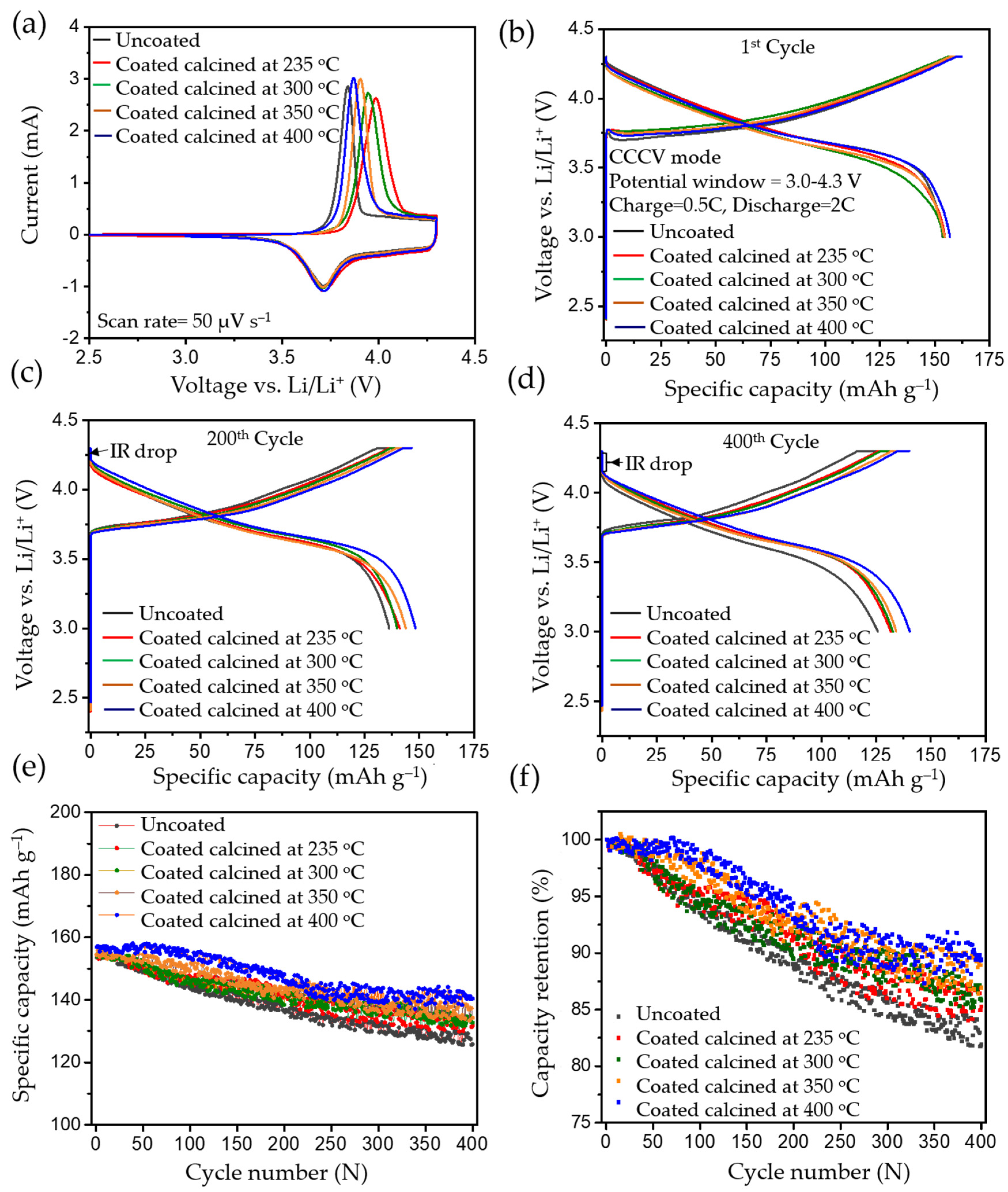
2.6.1. Cyclic Voltammetry

To investigate the influence of the coating on electrochemical performance, cyclic voltammetry (CV), charge–discharge, rate-capability tests, and impedance studies were carried out. Figure 8a shows the first cycle of CV comparing uncoated pristine and coated/calcined samples. For the uncoated pristine material, an oxidation peak at ~3.85 V vs. Li/Li+ and a reduction peak at ~3.70 V vs. Li/Li+ during the first cycle can be observed, corresponding to oxidation and reduction of the Ni2+/4+ redox couple [1]. Cyclic voltammetry revealed that coating thickness and temperature had no impact on either the uncoated or the coated materials upon cathodic scan, showing a stable reduction peak (Figure 8a). However, in the first cycle the voltage difference between the anodic and cathodic peaks was higher for the coated samples compared to the uncoated ones (~0.126 V), and as the temperature of calcination increased to 235 °C, 300 °C, 350 °C, and 400 °C, the voltage difference decreased to 0.273 V, 0.235 V, 0.194 V, and 0.156 V, respectively. The increase in the voltage difference can be mainly attributed to a shift to higher potential for the first anodic peak. This can be explained by a hindered Li+ diffusion in the first anodic scan, which was exacerbated with the increase in thickness of the coated layer on top of the particles. However, from the second scan onwards the offset of the anodic peak shifted to lower potentials, since all the coated calcined samples were forming stable cathode electrolyte interfaces (CEIs) [2]. During subsequent cycles, Ni2+/4+ redox couples remained unchanged for the carbon coated samples.

2.6.2. CCCV Charge and CC Discharge

In CCCV experiments, typical charge–discharge profiles for NMC type materials were observed for pristine and calcined NMC622 cathode materials in the 1st, 200th, and 400th cycle, which are shown in Figure 8b, Figure 8c, and Figure 8d, respectively; testing was conducted at 2 C (where 1 C = 160 mAh g−1) in the potential window of 3.0–4.3 V vs. Li/Li+. All cells were subjected to formation cycles at 0.1 C for the first five cycles, to form a stable CEI layer at the interface to adjust for high discharge loads in the successive cycles. All tests for NMC show typical progressive and retrogressive charge–discharge curves (Figure 8b). When comparing the formation cycles of freshly prepared cells, a similar behaviour in relation to CV measurements can be observed. The overpotential increased (higher charge plateaus) during charging for calcined in comparison to uncoated materials and most likely can be related to a reduced Li+ ion diffusion. This phenomenon can be clearly related to the thickness of the coating (see Figure S4). Also, CCCV experiments gave similar discharge curves compared to CV for all samples. During the first cycle, the charge plateau for uncoated samples started at ~3.70 V, at ~3.74 V for the coated ones, and it continued to increase to ~3.77 V as the thickness of the coating increased. A potential increase at the very beginning of the charge curve can be observed, which is attributed to the change of the current rate (0.1 C to 0.5 C) after formation, the thickness of the coating layer, and surface impurities [8]. However, the discharging profiles of pristine and calcined materials are similar without noticeable difference in the ohmic drop (IR drop). After 200 cycles, an increase in the IR drop can be seen with a similar charge–discharge behaviour, which is mainly due to the rise of internal resistance, as shown in Figure 8c. This was caused by the accumulated products from side reactions over 200 cycles and resulted in the drop of potential at the beginning of discharge. However, the IR drop or ohmic polarisation was less in the case of calcined compared to uncoated materials and showed its lowest values for the thinnest coatings. Similarly, the concentration polarisation was lower for calcined compared to the uncoated samples, which is attributed to the mass transfer within the cell during charge–discharge. This further confirms an improved charge–discharge performance for carbon coated samples. It can also be assigned to the better percolation network, which improves the electronic conductivity of the particle and leads to fewer side reactions stemming from the metal-oxide surface. Likewise, after the 400th cycle, much higher polarisation losses can be observed in the uncoated sample compared to the calcined material (seen in Figure 8d). The increase in polarisation was mainly caused by the increase in internal resistance, which may have originated from surface side reactions. Figure 8e shows the cycling performance of the uncoated and cells with calcined NMC materials over 400 cycles, performed at a 2 C discharge rate. The discharge capacity at the first cycle after formation for NMC powders calcined at 235 °C, 300 °C, 350 °C, and 400 °C delivered values ranging from 153.59 mAh g−1 to 156.98 mAh g−1. The same order of capacity decrease can be observed after completing 400 cycles with discharge capacities ranging from 125.80 mAh g−1 to 140.36 mAh g−1 as shown in Table 4. As a result, higher capacity retention can be observed in the coated materials, which increased with thinner coatings (85.29%, 85.56%, 86.93%, and 89.42%). In contrast, the uncoated NMC622 shows only 81.38% from the first cycle as shown in Figure 8f. Hence, coated calcined samples give better performance and higher capacity retention upon long-term cycling and it is believed this performance improvement is directly related to the amorphous carbon surface coating. A comparison of previously reported studies related to the long-term cycling stability of coated materials can be found in Table S2, highlighting the improved capacity retention that can be achieved with the materials reported in this work.

2.6.3. Cycling Experiments of Heat Treated Uncoated Pristine NMC622

To confirm the effect of the calcination on the performance improvement of the NMC material, samples treated at elevated temperatures, but without carbon coating, were tested under the same conditions and compared with the coated samples. Rietveld refinement analysis was carried out and is presented in Figure S5 and Table S1. The clear peak splitting at ~38° and ~65° 2θ corresponds to (006)/(102) and (108)/(110) hkl planes, which indicates the high crystallinity of the materials after heating. Lattice parameter values of (003)/(104) >1.2 indicate no obvious cation mixing in the structure [1,39,40]. Their cycling performance was tested under the same conditions as the coated samples, depicted in Figure S6. Specimens calcined at different temperatures, namely, 235 °C, 300 °C, 350 °C, and 400 °C, delivered discharge capacities after the first cycle ranging from 155.18 mAh g−1 to 156.46 mAh g−1. For cells cycled 400 times, discharge capacities in the range of 128.89 mAh g−1 to 134.27 mAh g−1 were observed, which gives capacity retentions of 83.06%, 84.28%, 84.37%, and 85.81%, respectively as shown in Table 5. These findings are in agreement with published data where the improvement in capacity retention originates from the removal of the surface impurities (LiOH, Li2CO3) during the heat treatment, and from the enhancement of crystallinity due to the heating step [3,7,8]. Hence, the heat treatment of NMC particles results in improved performance. However, the amorphous carbon coating presented in this paper further improves performance during the long-term cycling and has a high C-rate testing.

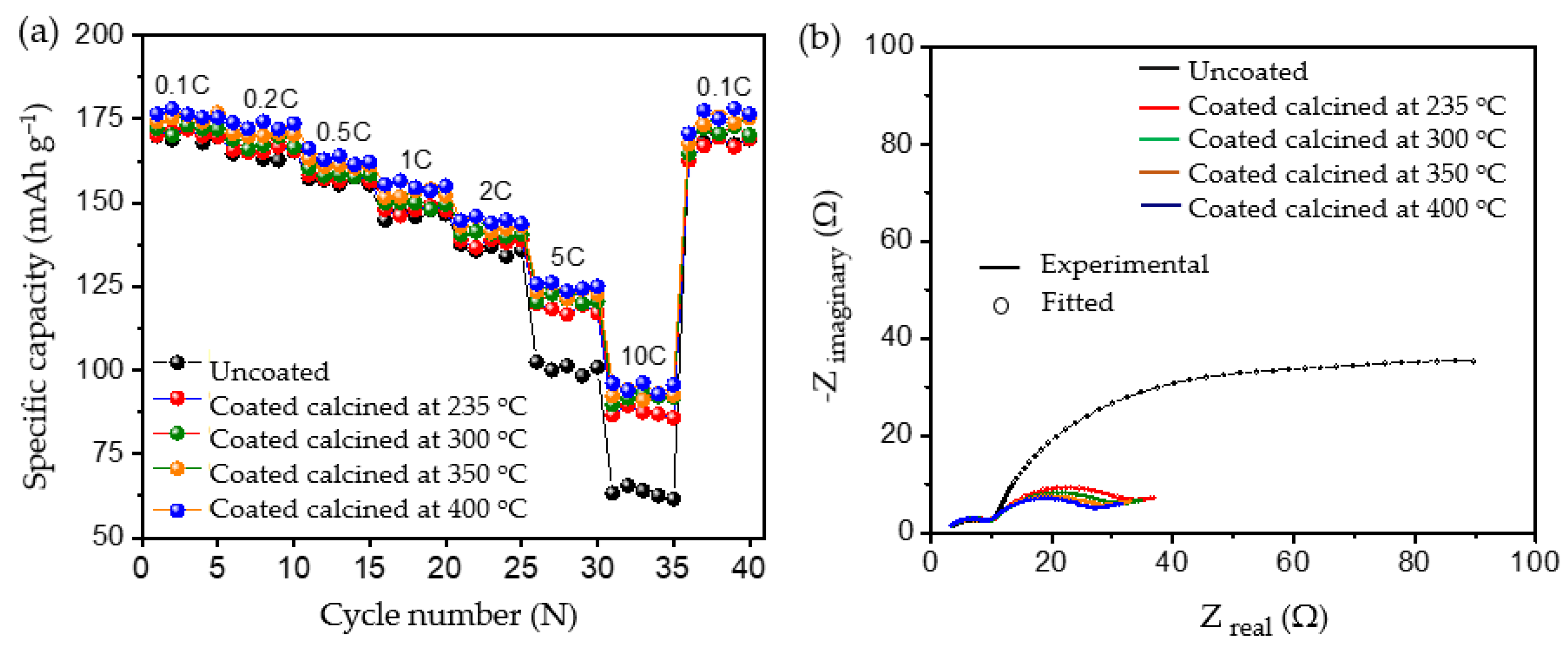
2.6.4. Rate Capacity and Electrochemical Impedance Spectroscopy Test

To evaluate the robustness of the carbon coatings at different loads of current, rate capability testing was carried out as shown in Figure 9a. At lower current rates such as 0.1 C, 0.2 C, 0.5 C, 1 C, and 2 C, both the uncoated and coated materials delivered similar discharge capacities, without significant differences in discharge performance. However, when higher loads of current such as 5 C and 10 C were applied, all the coated calcined samples delivered significantly increased discharge capacities compared to the uncoated pristine material; see Table 6. The improvement in the performance of the coated calcined material is directly proportional to the thickness of the coating layer; e.g., by reducing the thickness of the coating from ~100 nm (coated calcined at 235 °C) to ~15 nm (coated calcined at 400 °C), the discharge capacity at 10 C increased from 87.23 mAh g−1 to 94.97 mAh g−1, which relates to a nearly 9% capacity improvement. Also, when compared with the uncoated sample, which delivered only 63.41 mAh g−1 at 10 C, the calcined material at 400 °C showed a nearly 50% improvement in the discharge capacity. Comparing high current tests of NMC622 coated with ~15 nm amorphous carbon from this work with state-of-the-art coated materials shows excellent performance for high currents of 10 C at discharge (see Table S3).
To determine the reason for the presented performance enhancement, electrochemical impedance spectroscopy studies for uncoated and all calcined samples were performed after the formation cycle. Therefore, cells were charged to a nominal voltage (3.8 V) before acquiring impedance data. The results are shown in Figure 9b. From the perspective of the qualitative analysis, the coated calcined samples showed lower charge transfer resistance (Rct) compared to the uncoated samples. That is, the charge transfer resistance of the coated materials decreased with the thickness of the coating, indicating the formation of a thinner and more stable CEI layer on top of the material. Furthermore, the charge transfer resistance for Li+ was reduced by providing optimum encapsulation with amorphous carbon as a layer on top of the particles and as a result improved ionic conductivity. The lower charge transfer resistance of samples calcined at 400 °C may be one of the reasons for the higher rate performance at 10C due to the improved percolation pathways for Li+ movement and enhanced electric conductivity. However, to quantify the improvement, the detailed analysis of the obtained spectra was carried out using the electrical equivalent circuit shown in Figure S7, where Rsol represents the electrolyte and cell resistance The parallel CPEsei and Rsei represent the capacitive nature and resistance of the passivation layer on the electrode–electrolyte interface, respectively (i.e., the small arc at high frequencies region). The next parallel constant phase element (CPEdl) and Rct represent the charge-transfer process (i.e., the dominating arc in the Nyquist plots). The generalised finite space Warburg (GFW) is used to fit the diffusion component of the plot [50]. Since the lithium ion intercalates into the cathode during the discharge process through the SEI layer followed by diffusion in the bulk, the GFW element is added in parallel CPEdl and series to Rct [51]. The constant phase element (CPE) is used instead of the capacitor, due to its non-ideal capacitor nature attributed to the electrode surface inhomogeneity or dispersed charge-transfer reactions [51]. The exponential parameter “P” is used to describe its deviation from the ideal capacitor.
Table 7 shows the obtained best fit values of the uncoated and coated samples, where the low error in the determination of each component shows a good quality of fit and high reliability of the performed fit. The Rsol values do not deviate much during each measurement, indicating high reproducibility in cell assembly and measurements. The lower value of Rsei was found in different samples due to the thin electrodes (low active material loading per area). The variation of Rct in different coating thicknesses was found to be more dominating. The deviation of Rct was found to be from 20.11 Ω to 15.01 Ω with the thickness of the carbon coating ranging from ~100 nm to ~15 nm, respectively. However, the value in the uncoated sample, found to be 54.11 Ω, is much higher, which underlines the positive impact of the amorphous carbon coating on cell performance. The smaller Rct values for the coated samples compared to the uncoated materials relates to the surface deintercalation–intercalation of lithium ions in the cathode during the charge–discharge process. Accordingly, upon comparing the coated and uncoated electrodes, owing to the lower value of charge-transfer resistance in the amorphous carbon coated samples, a better Li+ intercalation–deintercalation was observed. Further, a strong dependency on the thickness of the coating layer to charge-transfer resistance can be seen, where Rct values decrease as the thickness of the coating reduces.

2.7. Post-Mortem Analysis

Post-mortem analysis was conducted after 400 charge–discharge cycles to reveal the underlying processes that cause improved performance for coated materials compared to untreated NMC. Figure 10 shows the XRD and SEM analyses carried out on the uncoated and NMC calcined at 400 °C. The cells were disassembled inside a glove box and washed gently with dimethyl carbonate (DMC) to remove any residual LiPF6 salt. The XRD of the cycled electrodes shows clear peak splitting of (006)/(102) and (108)/(110) hkl planes for the coated materials, while uncoated pristine NMC622 shows low intense peaks as highlighted in Figure 10; the arrival of new shoulder peaks and the broadening of the (110) peak indicate the partial loss of hexagonal order in the crystal lattice. When comparing electrodes after 400 cycles, specimens calcined at 400 °C show higher crystallinity in comparison with untreated pristine NMC622 (Figure 10a). SEM analysis reveals that heat treatment and galvanostatic cycling has no impact on primary and secondary particle morphology (Figure 10b,c).

3. Materials and Methods

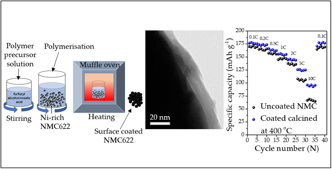
3.1. Material Preparation

Commercially available NMC622 (BASF, HED™) with ~10 µm size, was used as the parent material. The carbon coating on NMC622 was achieved via polymerisation of furfuryl alcohol (FA) (≥98% (a/a), Merck KGaA, Gernsheim, Germany). Oxalic acid dihydrate (Merck KGaA, Germany) was used as the catalyst for the polycondensation reaction of furfuryl alcohol. The weight ratio of NMC622 to FA was adjusted to 6:1. The FA to oxalic acid ratio was maintained at 1 wt.% of FA, and then the NMC622 powders were dispersed in the solution of FA, followed by heating to 80 °C. Once the reactants became a gel, it was cured at 120 °C for 1 h. To obtain the carbon coating on NMC622, the cured powders were calcined at 235 °C, 300 °C, 350 °C, and 400 °C, respectively, for 2 h in air as shown in Figure S1.

3.2. Physico-Chemical Characterisation

The phase identification was carried out by powder X-ray diffraction (PXRD) using an X’Pert Pro diffractometer (Malvern/Panalytical) equipped with Cu Kα radiation (λ = 1.54060 Å). The PXRD patterns were collected between 10 and 120° (2θ) and a scan speed of 0.01061°/s. The specimen displacement, peak deconvolution, and unit cell parameters were refined by Rietveld analysis within the Highscore Plus software package. For the standard reference pattern LiNi0.65Mn0.1Co0.25O2 (98-015-9318), the correct atomic occupancy for NMC622 (Li1Ni0.60Mn0.2Co0.2O2) was considered. A scanning electron microscope SEM (Supra 40, Carl Zeiss AG, Oberkochen, Germany) was used to investigate the morphology of carbon coated and uncoated NMC622 powders. A detailed examination of the thickness and homogeneity of the coating was investigated by transmission electron microscopy TEM (TECNAI F20, FEI Company, Hillsboro, OR, USA). The elemental distribution was analysed by energy dispersive X-ray spectroscopy (EDX, EDAX Inc., Mahwah, NJ, USA). Attenuated total reflectance-Fourier-transform infrared spectroscopy (ATR-FTIR, PerkinElmer, Inc., Waltham, MA, United States) was used to determine organic functional groups. The thermal decomposition of the polymer coated NMC622 was observed using a NETZSCH STA 449 F1 thermobalance, and thermogravimetric analysis (TGA) with a differential thermal analysis sensor (DTA) coupled with a 403 Aëolos Quadro quadrupole mass spectrometer (Erich NETZSCH GmbH & Co. Holding KG, Selb, Germany) was used to determine the gas evolved during the decomposition reaction. The XPS-spectrometer (SPECS, Berlin, Germany) consists of a monochromatic (Al-Kα = 1486.6 eV) radiation source (µFocus 350) and a hemispherical energy analyzer with a wide-angle lens (PHOIBOS-150, acceptance angle: 60°, mean angle: 51° to sample surface normal). Pass energies of 100 eV and 30 eV and step widths of 0.5 eV and 50 meV were used to obtain the survey and high-resolution spectra, respectively. Measurements were conducted at 3 × 10⁻⁹ mbar, where the base pressure of the system was 1 × 10⁻⁹ mbar. To confirm the linearity of the binding energy (BE), scale methods described in ISO15472 were used. The instrument resolution was determined by measuring the Ag 3d5/2 signal of sputter cleaned silver. The data analysis was carried out by using CASA XPS software (Casa Software Ltd, UK), applying Scofield sensitivity factors [52] and transmission correction Shirley/Tougaard backgrounds [53,54]. Charge correction was carried out by shifting the adventitious carbon peak (C–C peak) to 285.0 eV binding energy. Elemental analysis (CHN) was carried out with a Perkin Elmer 2400CHN elemental analyser (PerkinElmer, Inc., Waltham, MA, USA).

3.3. Cell Preparation and Electrochemical Measurement

Pristine NMC622, carbon coated NMC622 powders as active material, in this publication called AM, and carbon black (CB) from Imerys S.A. (super-C65) were dried at 100 °C for 2 h. Manual mixing was carried out in an agate mortar. Small portions of 7 wt.% polyvinylidene fluoride (PVDF, SOLEF 5130) in N-methyl pyrrolidone (NMP) solution were added dropwise and mixed thoroughly until it formed a homogenous mixture. The dough-like mixture was transferred to a glass beaker, where the rest of the PVDF–NMP solution was added. The weight ratio of AM, CB, and PVDF was adjusted to 90:5:5 with a solid content of the slurry of 40 wt.% and stirred for 12 h. A 120 µm thick film was coated on a 16 µm aluminium foil using a doctor blade. The coating was dried at 60 °C in air for 30 min followed by 120 °C for 2 h in a vacuum oven. After this procedure, the electrode was calendared at 120 °C, where 35–40% of the porosity was retained. Electrodes were punched as 15 mm discs and subjected to another heating step at 120 °C under high vacuum for 12 h before being transferred into a glove box.
Considering a specific AM capacity of 160 mAh g−1, the average areal loading (8.5 ± 0.5 mg cm−2) of AM gave an average areal capacity of 1.4 ± 0.1 mAh cm−2. The CR2016 coin type half-cells with the NMC622 electrode active material, Celgard separator, and Li foil were assembled in an argon-filled glove box (M. BRAUN INERTGAS-SYSTEME GMBH, Garching, Germany), where H2O and O2 contents were <0.1 ppm. A volume of 100 µL of a 1M LiPF6 in ethylene carbonate (EC)):ethyl methyl carbonate (EMC) = 3:7 (w/w), and 2 wt.% vinylene carbonate (VC) (SoulBrain) solution was used as an electrolyte and added to wet the micropores of the polypropylene membrane (Celgard 2500) separators. For charge–discharge and rate capability tests, constant current constant voltage (CCCV) measurements were conducted on a Maccor Series 4000 battery tester in the voltage range of 3.0–4.3 V at 0.1 C (where 1 C = 160 mAh g−1) for the first five cycles’ formation, followed by 0.5 C for CCCV charging (CV until the current reaches 0.05 C) and 2.0 C for CC-discharging. The cyclic voltammetry (CV) was performed with a scan rate of 50 µV s−1 in the potential range of 3–4.3 V vs. Li/Li+. Electrochemical impedance spectroscopy (EIS) was carried out with an amplitude voltage of 10 mV and a frequency range of 100 mHz to 3 KHz, using a BioLogic VSP electrochemical workstation. All the electrochemical measurements were then performed at a constant temperature of 25 °C.

4. Conclusions

An amorphous carbon coating was successfully applied onto NMC622 materials by acid catalyst polymerisation of furfuryl alcohol followed by a calcination step for the first time. The XRD analysis showed the phase stability of NMC622 at various temperatures, SEM images showed complete coverage of NMC samples with carbon, and TEM images further confirmed the carbon coating and showed variations in the thickness of the coating as a function of the calcination temperature as well as uniformity. Additionally, XPS analysis showed the temperature dependency of the carbon coating, which was confirmed by the TEM analysis of the coated NMC samples. Furthermore, a detailed electrochemical analysis was performed to investigate the effect of the surface coating on the performance of the NMC622, and the long-term cycling of the coated samples showed improved electrochemical performance; in particular, the 15–20 nm carbon coatings showed better capacity retention and an improvement of 8% after 400 cycles. The improvement in the long-term cycling performance of the coated calcined samples shows their low electrode–electrolyte side reactions over 400 cycles. Apart from long-term performance, the coated calcined sample showed nearly 50% capacity improvement compared with the uncoated one when cycled at 10 C provided by a better percolation network. The high-rate performance improvement was further analysed by electrochemical impedance analysis, where the coated calcined samples showed lower charge-transfer resistance than the uncoated samples, which creates optimum conditions for the Li+ ions to transfer from the bulk to the surface of the electrode. Additionally, for the role of heat treatment on the NMC particles, the systematic heating on the uncoated particles was carried out, showing the remaining structural stability of the NMC622 and resulting in improved capacity after 400 cycles. PXRD in post-mortem analysis showed less crystallinity for the uncoated materials compared to 400 °C calcined NMC. However, the SEM analysis showed no major difference in particle size in both materials. Hence, the optimum carbon coating without inert atmosphere improved the long-term cycling as well as the high-rate performances. Furthermore, comparing the results with the state-of-the-art reported coating materials for nickel-rich cathodes, the present coating strategy to obtain a thin coating of ~15 nm at 400 °C showed excellent capacity retention after the run of 400 complete cycles at 2 C discharge rate and a good upgrade in the C-rate performances, especially at a 10 C discharge rate, where nearly 50% enhancement was observed. In future, the study at higher potentials, in combination with state-of-the-art anodes to fabricate full cells, will help to enable high-power applications.

Supplementary Materials

The following graphs and tables are available online at https://www.mdpi.com/article/10.3390/batteries7040069/s1, Figure S1: Schematic of synthesis process; Figure S2: XPS detail spectra for (a) C 1s and (b) Ni 2p regions; Figure S3: EDAX analysis of (a) uncoated pristine NMC622, (b) Coated calcined at 235 °C, (c) coated calcined at 300 °C, (d) coated calcined at 350 °C, and (e) coated calcined at 400 °C for 120 min duration; Figure S4: Formation cycle profile of uncoated and coated calcined NMC622 sample carried at 0.1C current rate; Figure S5: XRD patterns of (a) uncoated pristine NMC622, (b) uncoated calcined at 235 °C, (c) uncoated calcined at 300 °C, (d) uncoated calcined at 350 °C, and (e) uncoated calcined at 400 °C for 120 min duration; Figure S6: Cycling performance of the uncoated NMC622 and uncoated calcined at 235 °C, 300 °C, 350 °C, and 400 °C; Figure S7: Equivalent electrical circuit for the impedance analysis of the uncoated and coated samples; Table S1: The lattice parameters of the uncoated and the coated heated NMC622 samples; Table S2: Comparison of previously reported different surface coating materials to improve their long-term electrochemical cycling performance; Table S3: Comparison of previously reported different surface coating materials to improve their high current electrochemical performances.

Author Contributions

Conceptualization, A.R.K. and J.K.; methodology, A.R.K. and J.K.; validation, J.K. and A.R.; formal analysis, A.R.K. and J.K.; investigation, A.R.K. and J.K.; resources, M.J.; data curation, A.R.K., J.K., D.L., R.H., and Y.S.; writing—original draft preparation, A.R.K. and J.K.; writing—review and editing, J.K.; A.R., D.L., M.B., J.V.M., A.H., and M.J.; visualization, A.R.K.; supervision, J.K.; project administration, J.K.; funding acquisition, M.J. All authors have read and agreed to the published version of the manuscript.

Funding

The authors gratefully acknowledge the financial support of the Austrian Federal Ministry for Climate Action, Environment, Energy, Mobility, Innovation and Technology, without which this research would not have been possible.

Institutional Review Board Statement

Not applicable.

Informed Consent Statement

Not applicable.

Data Availability Statement

Not available.

Acknowledgments

We acknowledge the Analytical Instrumentation Center of the Technische Universität Wien for providing XPS analysis and Xiaoxue Lu, Xinhua Zhu, and Mohammad Furquan for the scientific discussion. Special thanks to Jacqueline Winter for the review and language editing of the manuscript.

Conflicts of Interest

The authors declare no conflict of interest.

References

  1. Noh, H.-J.; Youn, S.; Yoon, C.S.; Sun, Y.K. Comparison of the structural and electrochemical properties of layered Li [NixCoyMnz] O2 (x = 1/3, 0.5, 0.6, 0.7, 0.8 and 0.85) cathode material for lithium-ion batteries. J. Power Sources 2013, 233, 121–130. [Google Scholar] [CrossRef]
  2. Lin, F.; Markus, I.M.; Nordlund, D.; Weng, T.C.; Asta, M.D.; Xin, H.L.; Doeff, M.M. Surface reconstruction and chemical evolution of stoichiometric layered cathode materials for lithium-ion batteries. Nat. Commun. 2014, 5, 3529. [Google Scholar] [CrossRef] [PubMed]
  3. Manthiram, A.; Song, B.; Li, W. A perspective on nickel-rich layered oxide cathodes for lithium-ion batteries. Energy Storage Mater. 2017, 6, 125–139. [Google Scholar] [CrossRef]
  4. Myung, S.-T.; Maglia, F.; Park, K.-J.; Yoon, C.S.; Lamp, P.; Kim, S.-J.; Sun, Y.-K. Nickel-rich layered cathode materials for automotive lithium-ion batteries: Achievements and perspectives. ACS Energy Lett. 2017, 2, 196–223. [Google Scholar] [CrossRef]
  5. Schipper, F.; Erickson, E.M.; Erk, C.; Shin, J.-Y.; Chesneau, F.F.; Aurbach, D. Review—Recent Advances and Remaining Challenges for Lithium Ion Battery Cathodes. J. Electrochem. Soc. 2016, 164, A6220–A6228. [Google Scholar] [CrossRef]
  6. Kim, J.; Lee, H.; Cha, H.; Yoon, M.; Park, M.; Cho, J. Prospect and reality of Ni-rich cathode for commercialization. Adv. Energy Mater. 2018, 8, 1–25. [Google Scholar] [CrossRef]
  7. Liu, W.; Oh, P.; Liu, X.; Lee, M.J.; Cho, W.; Chae, S.; Kim, Y.; Cho, J. Nickel-rich layered lithium transition-metal oxide for high-energy lithium-ion batteries. Angew. Chem. Int. Ed. 2015, 54, 4440–4457. [Google Scholar] [CrossRef] [PubMed]
  8. Herzog, M.J.; Gauquelin, N.; Esken, D.; Verbeeck, J.; Janek, J. Increased Performance Improvement of Lithium-Ion Batteries by Dry Powder Coating of High-Nickel NMC with Nanostructured Fumed Ternary Lithium Metal Oxides. ACS Appl. Energy Mater. 2021, 4, 8832–8848. [Google Scholar] [CrossRef]
  9. Li, T.; Yuan, X.-Z.; Zhang, L.; Song, D.; Shi, K.; Bock, C. Degradation mechanisms and mitigation strategies of nickel-rich NMC-based lithium-ion batteries. Electrochem. Energy Rev. 2019, 31, 43–80. [Google Scholar] [CrossRef] [Green Version]
  10. Zhu, W.; Huang, X.; Liu, T.; Xie, Z.; Wang, Y.; Tian, K.; Bu, L.; Wang, H.; Gao, L.; Zhao, J. Ultrathin Al2O3 Coating on LiNi0.8Co0.1Mn0.1O2 cathode material for enhanced cycleability at extended voltage ranges. Coatings 2019, 9, 92. [Google Scholar] [CrossRef] [Green Version]
  11. Wang, J.; Du, C.; Yan, C.; He, X.; Song, B.; Yin, G.; Zuo, P.; Cheng, X. Al2O3 coated concentration-gradient Li[Ni0.73Co0.12Mn0.15]O2 cathode material by freeze drying for long-life lithium ion batteries. Electrochim. Acta 2015, 174, 1185–1191. [Google Scholar] [CrossRef]
  12. Jian, Z.; Wang, W.; Wang, M.; Wang, Y.; AuYeung, N.; Liu, M.; Feng, Z. Al2O3 coated LiCoO2 as cathode for high-capacity and long-cycling Li-ion batteries. Chin. Chem. Lett. 2018, 29, 1768–1772. [Google Scholar] [CrossRef]
  13. Schipper, F.; Bouzaglo, H.; Dixit, M.; Erickson, E.M.; Weigel, T.; Talianker, M.; Grinblat, J.; Burstein, L.; Schmidt, M.; Lampert, J.; et al. From surface ZrO2 coating to bulk Zr doping by high temperature annealing of nickel-rich lithiated oxides and their enhanced electrochemical performance in lithium ion batteries. Adv. Energy Mater. 2018, 8, 1701682. [Google Scholar] [CrossRef]
  14. Tao, T.; Chen, C.; Yao, Y.; Liang, B.; Lu, S.; Chen, Y. Enhanced electrochemical performance of ZrO2 modified LiNi0.6Co0.2Mn0.2O2 cathode material for lithium ion batteries. Ceram. Int. 2017, 43, 15173–15178. [Google Scholar] [CrossRef]
  15. Laskar, M.R.; Jackson, D.H.K.; Xu, S.; Hamers, R.J.; Morgan, D.; Kuech, T.F. Atomic layer deposited MgO: A lower overpotential coating for Li[Ni0.5Mn0.3Co0.2]O2 cathode. ACS Appl. Mater. Interfaces 2017, 9, 11231–11239. [Google Scholar] [CrossRef]
  16. Zhang, H.; Xu, J.; Zhang, J. Surface-coated LiNi0.8Co0.1Mn0.1O2 (NCM811) cathode materials by Al2O3, ZrO2, and Li2O-2B2O3 thin-layers for improving the performance of lithium ion batteries. Front. Mater. 2019, 6, 309. [Google Scholar] [CrossRef]
  17. Hildebrand, S.; Vollmer, C.; Winter, M.; Schappacher, F.M. Al2O3, SiO2 and TiO2 as coatings for safer LiNi0.8Co0.15Al0.05O2 cathodes: Electrochemical performance and thermal analysis by accelerating rate calorimetry. J. Electrochem. Soc. 2017, 164, A2190–A2198. [Google Scholar] [CrossRef]
  18. Lu, X.; Zhang, N.; Jahn, M.; Pfleging, W.; Seifert, H.J. Improved capacity retention of SiO2 -coated lithium-ion batteries. Appl. Sci. 2019, 9, 3671. [Google Scholar] [CrossRef] [Green Version]
  19. Kong, J.-Z.; Ren, C.; Tai, G.-A.; Zhang, X.; Li, A.-D.; Wu, D.; Li, H.; Zhou, F. Ultrathin ZnO coating for improved electrochemical performance of LiNi0.5Co0.2Mn0.3O2 cathode material. J. Power Sources 2014, 266, 433–439. [Google Scholar] [CrossRef]
  20. Xie, Z.; Zhang, Y.; Yuan, A.; Xu, J. Effects of lithium excess and SnO2 surface coating on the electrochemical performance of LiNi0.8Co0.15Al0.05O2 cathode material for Li-ion batteries. J. Alloys Compd. 2019, 787, 429–439. [Google Scholar] [CrossRef]
  21. Loghavi, M.M.; Mohammadi-Manesh, H.; Eqra, R. Y2O3-decorated LiNi0.8Co0.15Al0.05O2 cathode material with improved electrochemical performance for lithium-ion batteries. J. Electroanal. Chem. 2019, 848, 113326. [Google Scholar] [CrossRef]
  22. Li, X.; Jin, L.; Song, D.; Zhang, H.; Shi, X.; Wang, Z.; Zhang, L.; Zhu, L. LiNbO3-coated LiNi0.8Co0.1Mn0.1O2 cathode with high discharge capacity and rate performance for all-solid-state lithium battery. J. Energy Chem. 2020, 40, 39–45. [Google Scholar] [CrossRef] [Green Version]
  23. Shen, B.; Liu, Q.; Wang, L.; Yin, G.; Zuo, P.; Ma, Y.; Cheng, X.; Du, C.; Gao, Y. Mixed lithium ion and electron conducting LiAlPO3.93F1.07-coated LiCoO2 cathode with improved electrochemical performance. Electrochem. commun. 2017, 83, 106–109. [Google Scholar] [CrossRef]
  24. Chen, X.; Ma, F.; Li, Y.; Liang, J.; Matthews, B.; Sokolowski, J.; Han, J.; Wu, G.; Lu, X.; Li, Q. Nitrogen-doped carbon coated LiNi0.6Co0.2Mn0.2O2 cathode with enhanced electrochemical performance for Li-Ion batteries. Electrochim. Acta 2018, 284, 526–533. [Google Scholar] [CrossRef]
  25. Mauger, A.; Julien, C. Surface modifications of electrode materials for lithium-ion batteries: Status and trends. Ionics 2014, 20, 751–787. [Google Scholar] [CrossRef]
  26. Chen, Z.; Zhang, Z.; Liu, P.; Wang, S.; Zhang, W.; Chen, D. Facile preparation of carbon-LiNi1/3Co1/3Mn1/3O2 with enhanced stability and rate capability for lithium-ion batteries. J. Alloys Compd. 2019, 780, 643–652. [Google Scholar] [CrossRef]
  27. Guo, R.; Shi, P.; Cheng, X.; Du, C. Synthesis and characterization of carbon-coated LiNi1/3Co1/3Mn1/3O2 cathode material prepared by polyvinyl alcohol pyrolysis route. J. Alloys Compd. 2009, 473, 53–59. [Google Scholar] [CrossRef]
  28. Dominko, R.; Bele, M.; Gaberscek, M.; Remskar, M.; Hanzel, D.; Pejovnik, S.; Jamnik, J. Impact of the carbon coating thickness on the electrochemical performance of LiFePO4/C composites. J. Electrochem. Soc. 2005, 152, A607–A610. [Google Scholar] [CrossRef]
  29. Sides, C.R.; Croce, F.; Young, V.Y.; Martin, C.R.; Scrosati, B. A high-rate, nanocomposite LiFePO4/carbon cathode. Electrochem. Solid-State Lett. 2005, 8, 484–487. [Google Scholar] [CrossRef]
  30. Singh, S.; Raj, A.K.; Sen, R.; Johari, P.; Mitra, S. Impact of Cl doping on electrochemical performance in orthosilicate (Li2FeSiO4): A density functional theory supported experimental approach. ACS Appl. Mater. Interfaces 2017, 9, 26885–26896. [Google Scholar] [CrossRef]
  31. Singh, S.; Panda, M.R.; Sen, R.; Johari, P.; Sinha, A.K.; Meena, S.S.; Mitra, S. Study of higher discharge capacity, phase transition, and relative structural stability in Li2FeSiO4 cathode upon lithium extraction using an experimental and theoretical approach and full cell prototype study. ACS Appl. Energy Mater. 2019, 2, 6584–6598. [Google Scholar] [CrossRef]
  32. Wang, L.-P.; Zhang, X.-D.; Wang, T.-S.; Yin, Y.-X.; Shi, J.-L.; Wang, C.-R.; Guo, Y.-G. Ameliorating the interfacial problems of cathode and solid-state electrolytes by interface modification of functional polymers. Adv. Energy Mater. 2018, 8, 1801528. [Google Scholar] [CrossRef]
  33. Babbar, P.; Niehoff, P.; Schappacher, F.; Winter, M. Studying the effects of carbon coatings on the electrochemical performance of LiNi1/3Co1/3Mn1/3O2. Meet. Abstr. 2018, MA2018-01, 359. [Google Scholar]
  34. Sim, S.-J.; Lee, S.-H.; Jin, B.-S.; Kim, H.-S. Use of carbon coating on LiNi0.8Co0.1Mn0.1O2 cathode material for enhanced performances of lithium-ion batteries. Sci. Rep. 2020, 10, 1–9. [Google Scholar] [CrossRef] [PubMed]
  35. Kong, L.; Guan, H.; Wang, X. In situ polymerization of furfuryl alcohol with ammonium dihydrogen phosphate in poplar wood for improved dimensional stability and flame retardancy. ACS Sustain. Chem. Eng. 2018, 6, 3349–3357. [Google Scholar] [CrossRef]
  36. Lascovich, J.C.; Giorgi, R.; Scaglione, S. Evaluation of the sp2/sp3 ratio in amorphous carbon structure by XPS and XAES. Appl. Surf. Sci. 1991, 47, 17–21. [Google Scholar] [CrossRef]
  37. Tondi, G.; Cefarin, N.; Sepperer, T.; D’Amico, F.; Berger, R.J.F.; Musso, M.; Birarda, G.; Reyer, A.; Schnabel, T.; Vaccari, L. Understanding the polymerization of poly-furfuryl alcohol: Ring opening and diels-alder reactions. Polymers 2019, 11, 2126. [Google Scholar] [CrossRef] [Green Version]
  38. Janus, R.; Wach, A.; Kuśtrowski, P.; Dudek, B.; Drozdek, M.; Silvestre-Albero, A.M.; Rodríguez-Reinoso, F.; Cool, P. Investigation on the low-temperature transformations of poly (furfuryl alcohol) deposited on MCM-41. Langmuir 2013, 29, 3045–3053. [Google Scholar] [CrossRef] [Green Version]
  39. Zhang, X.; Jiang, W.J.; Mauger, A.; Qilu; Gendron, F.; Julien, C.M. Minimization of the cation mixing in Li1+x(NMC)1-xO2 as cathode material. J. Power Sources 2010, 195, 1292–1301. [Google Scholar] [CrossRef]
  40. Lu, Z.; Beaulieu, L.Y.; Donaberger, R.A.; Thomas, C.L.; Dahn, J.R. Synthesis structure, and electrochemical behavior of Li [NixLi1/3-2x/3Mn2/3-x/3]O2. J. Electrochem. Soc. 2002, 149, A778–A791. [Google Scholar] [CrossRef]
  41. Julien, C. Local cationic environment in lithium nickel–cobalt oxides used as cathode materials for lithium batteries. Solid State Ionics 2000, 136–137, 887–896. [Google Scholar] [CrossRef]
  42. Kosova, N.V.; Devyatkina, E.T. Comparative study of LiCoO2 surface modified with different oxides. J. Power Sources 2007, 174, 959–964. [Google Scholar] [CrossRef]
  43. Choura, M.; Belgacem, N.M.; Gandini, A. Acid-catalyzed polycondensation of furfuryl alcohol: Mechanisms of chromophore formation and cross-linking. Macromolecules 1996, 29, 3839–3850. [Google Scholar] [CrossRef]
  44. Verdejo, R.; Lamoriniere, S.; Cottam, B.; Bismarck, A.; Shaffer, M. Removal of oxidation debris from multi-walled carbon nanotubes. Chem. Commun. 2007, 106, 513–515. [Google Scholar] [CrossRef] [PubMed]
  45. Branca, C.; Corsaro, C.; Frusteri, F.; Magazù, V.; Mangione, A.; Migliardo, F.; Wanderlingh, U. Structural and vibrational properties of carbon nanotubes by TEM and infrared spectroscopy. Diam. Relat. Mater. 2004, 13, 1249–1253. [Google Scholar] [CrossRef]
  46. Bertarione, S.; Bonino, F.; Cesano, F.; Jain, S.; Zanetti, M.; Scarano, D.; Zecchina, A. Micro-FTIR and micro-raman studies of a carbon film prepared from furfuryl alcohol polymerization. J. Phys. Chem. B 2009, 113, 10571–10574. [Google Scholar] [CrossRef] [PubMed]
  47. Singh, S.; Mitra, S. Improved electrochemical activity of nanostructured Li2FeSiO4/MWCNTs composite cathode. Electrochim. Acta 2014, 123, 378–386. [Google Scholar] [CrossRef]
  48. De Almeida Filho, C.; Zarbin, A.J.G. Porous carbon obtained by the pyrolysis of TiO2/poly (furfuryl alcohol) nanocomposite: Preparation, characterization and utilization for adsorption of reactive dyes from aqueous solution. J. Braz. Chem. Soc. 2006, 17, 1151–1157. [Google Scholar] [CrossRef] [Green Version]
  49. Czigány, Z.; Brunell, I.F.; Neidhardt, J.; Hultman, L.; Suenaga, K. Growth of fullerene-like carbon nitride thin solid films consisting of cross-linked nano-onions. Appl. Phys. Lett. 2001, 79, 2639–2641. [Google Scholar] [CrossRef]
  50. Wang, C.; Appleby, A.J.; Little, F.E. Electrochemical impedance study of initial lithium ion intercalation into graphite powders. Electrochim. Acta 2001, 46, 1793–1813. [Google Scholar] [CrossRef]
  51. Xu, K.; Lam, Y.; Zhang, S.S.; Jow, T.R.; Curtis, T.B. Solvation Sheath of Li + in nonaqueous electrolytes and its implication of graphite/electrolyte interface chemistry. J. Phys. Chem. C 2007, 111, 7411–7421. [Google Scholar] [CrossRef]
  52. Scofield, J.H. Hartree-Slater subshell photoionization cross-sections at 1254 and 1487 eV. J. Electron Spectros. Relat. Phenom. 1976, 8, 129–137. [Google Scholar] [CrossRef]
  53. Shirley, D.A. High-resolution X-ray photoemission spectrum of the valence bands of gold. Phys. Rev. B 1972, 5, 4709–4714. [Google Scholar] [CrossRef] [Green Version]
  54. Tougaard, S. Universality classes of inelastic electron scattering cross-sections. Surf. Interface Anal. 1997, 25, 137–154. [Google Scholar] [CrossRef]
Figure 1. FTIR analysis of the furfuryl alcohol monomer and cured polymerised coated NMC622.
Batteries 07 00069 g001
Figure 2. (a) TGA/DTA of the polymer coated NMC622 carried out in synthetic air atmosphere at 5 °C/min and 50 mL/min flow. (b) Mass spectroscopy of water (m/z 18) and carbon dioxide (m/z 44) of the respective TGA/DTA.
Batteries 07 00069 g002
Figure 3. XRD patterns of (a) uncoated pristine NMC622 and coated calcined NMC622 at (b) 235 °C, (c) 300 °C, (d) 350 °C, and (e) 400 °C for 120 min duration.
Batteries 07 00069 g003
Figure 4. FTIR spectrum of uncalcined polymer coated NMC622 and all calcined coated NMC622 samples.
Batteries 07 00069 g004
Figure 5. XPS survey spectra for the coated powder samples that are calcined at different temperatures.
Batteries 07 00069 g005
Figure 6. SEM images of (a) Uncoated NMC622 (b) NMC622 after 120 °C curing, (c) At 235 °C calcinated sample, (d) At 300 °C calcinated sample, (e) At 350 °C calcinated sample, (f) At 400 °C calcinated sample for 120 min. duration.
Batteries 07 00069 g006
Figure 7. TEM images of polymer coated samples calcined at (a) 235 °C, (b) 300 °C, (c) 350 °C, and (d) 400 °C. (e) SAED pattern of the carbon derived from 235 °C calcination from the area highlighted in (f). (f) Mapped image of 400 °C, (g) mapping of all elements (Ni, Mn, Co, C), and (h) elemental mapping of carbon only.
Batteries 07 00069 g007
Figure 8. The electrochemical analysis of the uncoated and calcined samples carried out between 3 and 4.3 V vs. Li/Li+: (a) cyclic voltammetry, (b) 1st cycle charge–discharge profile, (c) 200th cycle charge–discharge profile, (d) 400th cycle charge–discharge profile, (e) cyclic performance for 400 cycles, and (f) respective capacity retention for 400 cycles (charge–discharge process was carried in CCCV mode, having CC=0.5 C and CV step until <0.05 C, and 2 C discharge).
Batteries 07 00069 g008
Figure 9. Rate capability tests for (a) uncoated and different coated materials and (b) electrochemical impedance spectroscopy for the uncoated and coated electrodes.
Batteries 07 00069 g009
Figure 10. (a) XRD of electrodes of uncoated pristine (top) and calcined samples, heat treated at 400 °C. (b) SEM of uncoated samples and (c) SEM of the calcined samples. Electrodes were collected after the completion of 400 cycles.
Batteries 07 00069 g010
Table 1. The lattice parameters of the coated/calcined and uncoated NMC622 samples.
Sample/Calcination Temperature acc/aI(003)/I(104)RwpGoodness of Fit (χ2)
(°C)(Å)(Å)
Uncoated pristine2.8681(2)14.2230(4)4.951.620.992.04
2352.8689(4)14.2317(8)4.961.651.032.07
3002.8692(3)14.2377(3)4.961.661.012.08
3502.8684(5)14.2329(4)4.961.641.052.10
4002.8680(2)14.2294(5)4.961.650.961.98
Table 2. Elemental quantification from XPS (estimated error =10% for values >10 at% and 15–20% for <10 at%).
Calcination TemperatureCNiO
(°C)(at%)(at%)(at%)
23552.3<147.7
30043.21.155.7
35045.21.653.2
40036.62.860.7
Table 3. Carbon quantification after calcination derived from CHN.
Calcination TemperatureCarbon Quantity
(°C)(wt.%)
2350.93 ± 0.03
3000.83 ± 0.03
3500.80 ± 0.02
4000.76 ± 0.02
Table 4. Specific discharge capacities (in mAh g−1) at 2 C of uncoated pristine compared to calcined samples after the 1st and 400th discharge cycle (standard deviation = ±2 mAh g−1).
Calcination TemperatureInitial CapacityFinal CapacityCapacity Retention
(°C)(mAh g−1)(mAh g−1)(%)
Uncoated pristine153.59125.8081.38
235154.51131.7385.29
300154.60132.6785.56
350154.41134.2386.93
400156.98140.3689.42
Table 5. Specific discharge capacities (in mAh g−1) at 2 C of uncoated pristine samples after the 1st and the 400th discharge cycle (standard deviation = ± 2 mAh g−1).
Calcination TemperatureInitial CapacityFinal CapacityCapacity Retention
(°C)(mAh g−1)(mAh g−1)(%)
Uncoated pristine153.59125.8081.38
235155.18128.8983.06
300155.05130.6884.28
350155.80131.4584.37
400156.46134.2785.81
Table 6. Specific discharge capacities (in mAh g−1) of uncoated and calcined samples (standard deviation = ±2 mAh g−1).
Untreated Pristine235 °C300 °C350 °C400 °C
Current Rate(mAh g−1)(mAh g−1)(mAh g−1)(mAh g−1)(mAh g−1)
0.1 C169.68170.61171.93174.35176.40
0.2 C164.28165.60167.66170.41173.20
0.5 C156.48157.21158.60161.38163.37
1 C146.46147.77149.51152.61155.01
2 C136.02138.33140.65143.11144.69
5 C100.60118.27120.96123.48124.99
10 C63.4187.2391.6692.6594.97
Table 7. Best fit values of uncoated and calcined samples.
Calcination Temperature Uncoated Pristine235 °C300 °C350 °C400 °C
ElementUnitsValueError (%)ValueError (%)ValueError (%)ValueError (%)ValueError (%)
Rsol(Ω)2.4430.0022.3120.0022.2910.0022.1570.0022.2650.001
CPEsei-T(Fsα−1)4.47 × 10−40.0064.10 × 10−40.0064.04 × 10−40.0060.0000.0074.04 × 10−40.006
CPEsei-P(/)0.6980.0010.7050.0010.7100.0010.7040.0010.7250.001
Rsei(Ω)8.5020.0018.4020.0018.4130.0018.0900.0028.0200.001
CPEdl-T(Fsα−1)3.35 × 10−30.0034.35 × 10−30.0044.22 × 10−30.0050.0040.0053.99 × 10−30.005
CPEdli-P(/)0.9230.0010.8710.0010.8630.0010.8600.0010.8790.001
Rct(Ω)54.1100.00720.1100.00517.9100.00516.3400.00515.0100.004
W-R(Ω)70.5500.00119.5600.02518.1200.02116.7700.01914.8700.014
W-T(s)5.8990.00210.9000.0569.8010.0488.1800.0416.8620.030
W-P(/)0.4190.0070.4190.0100.4200.0090.4210.0090.4290.007
Publisher’s Note: MDPI stays neutral with regard to jurisdictional claims in published maps and institutional affiliations.

