Abstract
Cycling Li-ion cells with large capacities requires high currents and hence an expensive measurement setup. Aging the Li-ion cell material in coin cells offers an orders-of-magnitude-lower power requirement to the battery tester. The preparation procedure used in this work allows one to build coin cells in a reproducible manner. The original 40 Ah pouch cells and the corresponding 4.3 mAh coin cells (PAT-Cell) utilizing electrode material from the original cells are cycled with 1C at different temperatures. The results show the same basic aging mechanisms in both cell types: loss of lithium inventory at room temperature but an increasing proportion of loss of active material toward higher temperatures. This is confirmed by similar activation energies in capacity degradation of the 40 Ah cells and the averaged coin cells. However, the capacity of the coin cells decreases faster over time. This is caused by diffusion of moisture into the coin cell housing. Nonetheless, the increasing water contamination over measurement time is not directly linked to the loss of capacity of the coin cells. Thus, the observed aging mechanisms of the 40 Ah cells can be qualitatively transferred to coin cell level.
1. Introduction
Aging investigations on Li-ion cells are time and cost intensive. The rate of aging depends on many factors, such as electrode materials; electrolyte composition; cell geometry; and the operational conditions SOC, C-rate, depth of discharge (DOD), and temperature. Thus, for each specific Li-ion cell type, many tests have to be carried out in order to create and parametrize a cell model, which is able to predict the aging behavior of the Li-ion cell. Therefore, electrode-specific aging studies may be helpful for developing more accurate aging models. By using the three-electrode-cells PAT-Cells by EL-CELL GmbH (hereinafter referred to as coin cell), the electrode potentials can be measured during cell testing and serve as additional information to understand the aging behavior.
Cycling the coin cells may reveal additional aging information; e.g., the influence of geometry on the cell performance: volume expansion during intercalation can cause stress in bent electrode layers in Li-ion cells [1] and the current distribution over the planar electrode area can be influenced by the current tabs positions, especially at higher C-rates [2,3]. In contrast, the electrodes used in PAT-Cells are not bent and the current collector contacted to the back of the electrodes should ensure a homogeneous current distribution. The PAT-Cells are assumed to be isothermal due to their limited electrode area and their thermal capacity. A more generalized, geometry-independent cell model, applicable to a wide field of cells of the same chemistry, might lower the needed number of measurements to adjust the battery model in the future. This work compares the aging behavior of the original Li-ion cell with the coin cells and is therefore a step towards this future goal.
Moreover, high-capacity Li-ion cells need a sophisticated and thus expensive experimental setup which is capable of providing high currents conforming to the safety regulations. As an alternative, aging the cell material in coin cells can tremendously lower both the required current and the safety regulations. Since only a small electrode area is required for building a coin cell, many coin cells can be assembled out of one original Li-ion cell. Hence, aging tests could be highly parallelized.
A prerequisite for this coin cell approach is a reproducible and minimum invasive extraction procedure. Our preparation method demonstrates a high reproducibility with a coefficient of variation in capacity of of 62 reassembled coin cells at beginning of life (BOL) [4]. The electrodes have not been washed during preparation [4] so that the electrolyte of the built coin cells is as identical as possible to the original electrolyte. Further information about our preparation and other extraction concepts is given in our previous study [4].
The aging process of Li-ion cells can have many causes [5,6]. NMC-based cathode materials can be degraded by structural deformation [7,8], manganese dissolution [5,9,10,11], corrosion of the current collector [5,9], the decomposition of the binder and the electrolyte, particle cracking, and the growth of a cathode interface layer [12,13,14]. On the graphite (GR) side, SEI growth [15,16], particle cracking [17,18], Li-Plating [19,20,21,22], and the incorporation of Mn-Ions into the SEI [5,10,23,24] can take place. The assignment of each single cause of aging to a specific electrical response behavior of a Li-ion cell is almost impossible [6]. Therefore, the causes which have similar electrical impacts on the cell are clustered together to loss of lithium inventory (LLI), loss of active material at the positive electrode (LAM), and loss of active material at the negative (LAM) electrode [6,25,26]. For instance, LLI is an indication for SEI growth which is the main cause of calendar aging [15,16,27,28,29] because Li is consumed to build up the SEI [15]. Once the cell is cycled, the changes in the volume of the GR can lead to cracks in the SEI structure (LLI) [17,18] and to a minor extent in the particle (LAM) [5]. Loss of electrical contact to the particles and structural disordering (e.g. in the positive electrode) are the typical causes for LAM.
In order to compare the cell aging behavior of the commercial Li-ion cells and the coin cells, the cell aging mechanisms have to be identified. Several methods have been introduced to detect the aging mechanisms [6,25,27,30,31,32,33]. Therefore, the characterization methods incremental capacity (IC), differential voltage (DV), maximum/minimum electrode potentials, electrochemical impedance spectroscopy (EIS), and pulse current measurements (PCM) are used and introduced in Section 2. After the experimental part in Section 3, Section 4 compares the 1C cyclic aging behavior of commercially manufactured 40 Ah Li-ion pouch cells to their extracted coin cells at the three specified temperatures C. In case of cycling at 1C, an aggravated capacity loss due to an inhomogeneous temperature distribution inside the 40 Ah cells can be neglected [34]. Finally, the aging mechanisms of both cell types are estimated.
The coin cells used for comparing to the original cells have an identical anode to cathode planar area ratio without any anode overhang which is different to the 40 Ah cells with . The electrochemical performance of Li-ion cells is sensitive to the anode overhang [35,36,37,38]. Therefore, an additional experiment in Section 5 is carried out to test the influence of the factor on the aging performance of the coin cells.
Traces of moisture and oxygen can hardly be avoided in reusable coin cell constructions. But some contamination by water is tolerable in the cell assembly process [39,40]. The PF from the dissociated LiPF reacts with water the following way:
Kawamura et al. measured the reaction rates of LiPF with water in an ethylene carbonate (EC):dimethyl carbonate (DMC) 50:50 vol.% solution at several temperatures [41]. The reaction rate is mainly driven by the viscosity and the polarization of the electrolyte [41]. The viscosities of DMC ( at C) and ethyl methyl carbonate (EMC) ( at C) and their relative permittivities ( and ) are similar [42,43]. Thus, it is possible to anticipate the reaction rate of water in the electrolyte used in this study ( in EC:EMC 30:70 wt.%). Therefore, another aging experiment in Section 6 shows the influence of the entry of moisture on the capacity loss of the coin cells with the help of EDX measurements.
Finally, a path dependency aging test is conducted for both cell types in Section 7. This investigation addresses the question of whether the capacity loss , consisting of a calendar and a cyclic aging part at certain time intervals and ,
is commutative. Two studies detected that the capacity loss during calendar aging is commutative [44,45]; however, the question arises of whether this independence of direction also applies to cyclic aging. A commutative aging behavior could lower the necessary number of measurements to predict the cell aging: If Equation (3) was valid, one side of this Equation could be determined without any measurement. Hence, cost intensive measurement time would be lowered. Additionally, this investigation is used to further prove the transferability of the proposed coin cell aging method to commercial cells.
2. Characterization Methods
A Gaussian filter
with and sampling points is used to process the data for the DV and IC analysis. We used a sampling rate of which is sufficient for the chosen C-Rate [46].
2.1. Differential Voltage
Figure 1a presents the DV of a NMC111-GR Li-ion coin cell at beginning of life (BOL). The GR stages are partly detectable by the full cell DV. The intercalation reaction of GR changes at about 20% SOC from (stage (IV) to (III)) to (stage (III) to (IIL)). This change is indicated by the local maximum in the full cell DV. The phase width is defined as the proportion of the SOC from 0% to this local maximum. The local maximum at about 50–60% SOC is linked to the change in reaction from () to () [27,47,48]. The phase width is the respective SOC value at this local maximum minus . Then, the third defined phase width is with the current cell capacity C. Figure 1b illustrates the definitions of the phase widths , , and for the respective full cell DV and the GR stages.
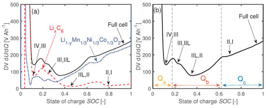
Figure 1.
(a) Differential voltages dU/dQ of the full cell and the electrode potentials of a coin cell at BOL. The phase transitions between the GR stages are visible in the full cell differential voltage (DV). (b) Phase widths , , and assigned to the full cell DV.
If the cell degrades because of LLI, the phase width is reduced since the GR electrode cannot be fully lithiated anymore. The phase widths and stay constant [6,27,46]. In case of LAM, all phase widths decline [6,27,46]. However, if there is an excess of negative active material compared to the positive, the detectable in the full cell stays constant in the early stages of aging due to the backup anode capacity, while and drop instantaneously. Subsequently, with the aging progresses, also decreases [31].
2.2. Incremental Capacity
Berecibar et al. simulated the effects of LLI, LAM, and LAM on the IC curves of NMC-GR Li-ion cells [25,33]. The authors linked the evolutions of characteristic features of interest (FOIs) from the IC curves to the aging mechanisms. The three FOIs highlighted in Figure 2 are considered for the IC analysis. The positions and the values of those peaks correlate to the SOHs of Li-ion cells [46]. Therefore, both attributes are used in this work for the identification of aging mechanisms. The individual influence of each mechanism on the attributes of the FOIs is summarized in Table 1.
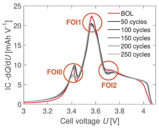
Figure 2.
Defined features of interest (FOIs) of the incremental capacity (IC) curves. Three characteristic extrema are detected: the first peak (FOI0) at , the main peak FOI1 at , and the local minimum FOI2 at about . The figure exemplary shows the changes in the FOIs for a cyclically aged coin cell.

Table 1.
General trend of the FOIs by the separated aging mechanisms [33]. The trends in this table are based on aged cells after 10% . Three arrows: Change in peak height bigger/smaller than 50% or change in position (voltage) bigger/smaller than 100 mV. Two arrows: 20–50% change of peak height or 40–100 mV change in the position. One arrow: 10–20% change in the peak height or 10–40 mV in position.
2.3. Electrode Potentials
The cell voltage is the difference in electrochemical potential between the positive and negative electrodes. During cycling, the cell voltage is limited within the boundaries and . However, the electrode potentials can shift relatively to each other during aging.
If a fully discharged cell (state (1) in Figure 3a) is charged and LLI is assumed as degradation mechanism, part of the Li will be lost during charging the cell () due to SEI growth. Hence, the GR will not get fully lithiated anymore [6], whereas the positive electrode will still get fully delithiated (2’). The result is a shift between the electrodes’ potentials. The GR potential at high degrees of lithiation is flat, which affects the cathode potential only slightly at the end of charge. In contrast, at the end of discharge the maximum anode potential increases significantly in case of LLI [6]. Therefore, the influence of LLI is mostly seen in the last part of the discharge process.
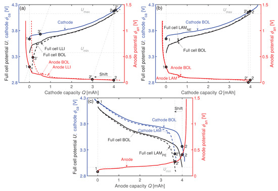
Figure 3.
Exemplarly impacts of (a) LLI, (b) LAM, and (c) LAM on the electrode balancing (e.g., the maximum and minimum anode potentials , ) of a measured coin cell.
Loss of negative active material LAM reduces the capacity of the negative electrode . This results in a smaller loading ratio . The minimum anode potentials , defined as the last data points during each cell charge in constant current (CC) mode, decrease [6,25] as seen in Figure 3b (). In contrast, LAM leads to an increasing . An indication is a decrease in [6,25] which is exemplarily shown in Figure 3c (). If a combination of LLI + LAM occurs with equal proportion, a constant is assumed as both mechanisms should cancel each other out.
2.4. Impedance
The internal resistance , the charge transfer resistance , and the double-layer capacitance , all measured by EIS, are defined as follows [49,50]:
The frequency is the eigenfrequency at the maximum point of the semi-circle in the Nyquist plot, is the real part and the imaginary part of the complex impedance , is the corresponding time constant, and the term is the ohmic impedance at the local minimum in the low-frequency imaginary part of the impedance curve.
Figure 4 shows the definitions of the PCM [50]. It presents the extracted points of the voltage curve after a pulse current applied for . The pulse duration complies with the standard IEC 62660-1. The internal resistance and the polarization resistance are defined as
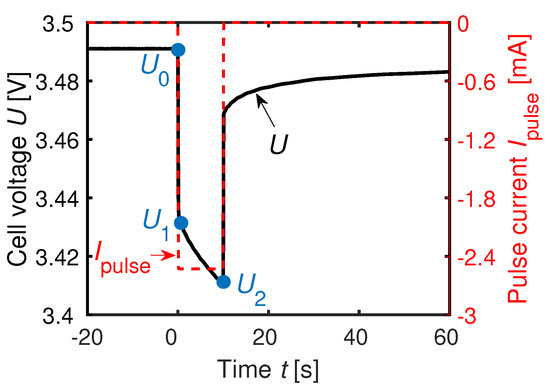
The voltage is the equilibrium cell potential before is been applied. The voltage is the instantaneous voltage drop resulting from the current flowing. The value is the voltage level after the current has been applied for [4,50,51].
3. Experimental
3.1. Commercial 40 Ah Li-Ion Pouch Cell
The cells used for this investigation are high-power 40 Ah Li-ion pouch cells with as cathode material and as anode material. Table 2 lists the cell specifications.

Table 2.
Information about the 40 Ah Li-ion pouch cell. Further information about this cell type can be found in [4,52,53].
3.2. Electrode Preparation
The pristine 40 Ah cells are discharged to their minimum voltage and opened inside a glove box. The extracted electrode sheets are not washed. The coating on one side of the double-coated GR electrode sheets is removed mechanically [4]. The first and the last layer of the cathode sheets are single coated and therefore used in this investigation. Using a solvent such as NMP to remove the coating is also possible and should not limit our proposed method [4]. The electrode cutter EL-CUT from EL-CELL GmbH (Germany) is used to cut the electrodes.
The coin cells are assembled on the same day the extraction is carried out. The PAT-Cell by EL-CELL GmbH [54] is used as cell housing. The separators Freudenberg Viledon FS 2226E + Lydall Solupor 5P09B with a total thickness of are used for the coin cell assembly. Each cell is filled with of EC:EMC 30:70 wt.% with 1 molar LiPF. Ethylene carbonate and EMC in the ratio 30:70 wt.% with 1 molar is assumed as electrolyte in the original cells since these components are listed in the cell manufacturer’s safety data sheet and since the mixing ratio 30:70 wt.% EC:EMC is commonly used [55]. Low-density polyethylene (LDPE) rings are used to seal the coin cells against air. The preparation process is described in detail in [4].
3.3. Influence of Sealing On Aging
Polyether ether ketone (PEEK) is used as another sealing material to investigate the influence of contamination by moisture and oxygen on the gathered results. The one-dimensional transmission rate of a species through a material relates to the material-specific diffusion constant D and the concentration gradient per way length . The diffusion constants for the sealing materials used are stated in Table 3.

Table 3.
Diffusion constants of moisture and oxygen in LDPE and PEEK [56,57,58].
Five cells are sealed with non-dried PEEK and five other cells with PEEK sealing rings which are dried in a vacuum oven before assembly at T = 80 C for t = 24. In addition, some coin cells with the standard LDPE seal are aged inside a glove box to exclude possible contamination by air. Except for the differences regarding sealing ring (PEEK) or ambient condition (glove box) respectively, the preparation and coin cell assembly are kept the same as for the other coin cells of this study. Table 4 lists the experiments.

Table 4.
Conducted sealing measurements: Two aging tests with modified material (PEEK, PEEK (dried)) and a test with LDPE sealing rings inside the glove box. The drying is carried out at 80 C for t = 24.
3.4. Anode Overhang Investigation
Twenty coin cells are assembled to investigate the influence of the missing anode overhang on the capacity degradation of the coin cells. In group 1, 10 modified coin cells with a ratio of 1.056, meaning a anode in diameter d against a cathode, are assembled. The other 10 cells from group 2 serve as a reference with . The tested cell configurations are listed in Table 5. After formation, all 20 cells are simultaneously cycled with 1C and 100% depth of discharge (DOD) (see Section 3.5) at room temperature using the same electrolyte, separator, and electrodes as for the other investigations.

Table 5.
Anode overhang investigation. Two different ratios are tested and declared as groups.
3.5. Test Procedure
A Gamry Reference 3000 connected to a BaSyTec Cell Test System via a multiplexer is used in this study. The BaSyTec is used for cell formation, cycling, and the pulse current measurement (PCM). The electrochemical impedance spectroscopy (EIS) is executed using the Gamry Reference 3000. Since the coin cells are filled with fresh electrolyte, three C/3 full cycles are carried out as an additional formation. Before performing the EIS and PCM, all cells are discharged to and then charged with constant current constant voltage (CCCV). The C-rate in the CC phase is C/3. The voltage of the constant voltage (CV) phase is () with the abortion criterion to obtain a steady SOC. The frequency for the EIS is set to the range . The measurement is carried out in potentiostatic mode with a voltage amplitude . The systematic error of the impedance measurement is [4]. The PCM consists of relaxation phases before and after the pulse current. The height of this pulse current is (discharge direction). The sample rate (resolution) of the PCM is set to .
3.5.1. Cyclic Aging
The cells are cycled within and (DOD = 100%) with CCCV in charge and CC in discharge direction. The CC rate is 1C. The abortion criterion in CV mode is . A capacity measurement at C/3 as well as PCM and EIS are carried out after every 50 cycles.
3.5.2. Calendar Aging
In calendar aging mode, the test loop includes charging the cells with CCCV at C/3 to () until is reached in CV mode. Then the capacity and impedance measurements are carried out, followed by a pause of 5 days. Due to the large amount of data, the results of calendrically aged coin cells will only be discussed in the Section 6.2 and Section 7.
3.6. SEM/EDX Measurements
The SEM device PHILIPS XL Series SEM from FEI Company with an EDAX NEW XL-30 EDX detector is used for this work. No direct detection of Li is possible by using this device. The set acceleration voltage is to observe the GR electrodes. The peak heights of the EDX spectra are taken for analysis. The respective peak heights are scaled to the measured carbon peak height to make measurements with different observation times comparable.
3.7. Path Dependency
One 40 Ah cell as well as four coin cells are first calendrically aged followed by a second cyclic aging part. Another 40 Ah cell and further four coin cells are aged in cyclic mode at the beginning. Then a subsequent calendar test procedure is carried out. It is ensured that the time durations and of the aging modes are the same for both 40 Ah cells and for both coin cell groups. The path dependency aging test is conducted at T = 35 C.
4. Aging Mechanism Identification
4.1. Impedance Spectroscopy At BOL
Figure 5a shows the characteristic points used for the EIS analysis. Figure 5b shows the spread and the qualitative shape of the EIS data of six 40 Ah and 28 assembled coin cells. Both the real and the imaginary parts of the impedances are scaled to their maximum values respectively. Compared to the 40 Ah cell, a second semi-circle can be observed for the coin cells. This might be caused by a changed SEI or due to the new interface between the current collectors and the stainless steel plungers. The absolute change in and the change in the diffusion tail might be caused by the thicker separator or due to the smaller electrode area of the coin cells [59].
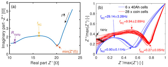
Figure 5.
(a) Exemplary Nyquist plot of a coin cell. The definitions of the characteristic points are from Equations (5)–(7). (b) Comparison of the normed impedances at BOL of the 40 Ah cells and the coin cells at . An additional second semi-circle at higher frequencies is observable for the coin cells. The characteristic frequencies are shown as . The black circles mark the 1 kHz values of the coin cells. The 1 kHz values of the 40Ah-cells are not shown here due to their inductive imaginary part.
4.2. Differential Voltage at BOL
Figure 6a,b gives an impression about the coin cells’ influence on the original electrochemical performance at BOL. Figure 6a presents the DV in discharge direction at T = 35 C with both curves being scaled to their local maximum in the lower range. The DV charge curves in Figure 6b are scaled to the local maxima within the SOC boundaries at T = 25 C.
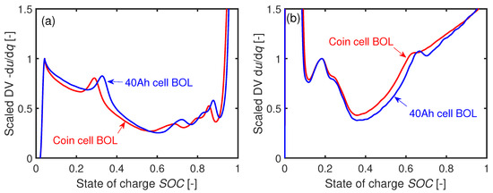
Figure 6.
Comparison of the DVs from a 40 Ah cell and a coin cell at BOL for (a) discharge with C/3 at C and (b) charge with C/3 at C.
The qualitative shapes between the 40 Ah and the coin cells are similar but there is a shift in in both cases. The phase width is sensitive to the Li inventory. When harvesting the electrode coins from the 40 Ah cell, inhomogeneously lithiated electrode areas may cause this shift of in the coin cell assembly.
4.3. Cyclic Aging
4.3.1. Capacity
The relative C/3 capacity curves of the original 40 Ah cells and the coin cells in Figure 7a correlate linearly to the times with high values, as seen in Table 6. The fit function used is . The first data points at 0 cycles are neglected for fitting. Table 6 also shows the fit function slope ratios between the 40 Ah and the coin cells for the three temperatures. The factor approximately remains constant between 8 and 8.5 and seems to be independent of temperature. This approximately eight-times-faster capacity loss of the coin cells cannot be explained by the different thermal capacities of the two cell types: Accelerated aging of the original cell due to an inhomogeneous cell temperature is neglected for 1C. In an aging study with prismatic 25 Ah NMC-GR Li-ion cells, an additional loss of capacity due to an inhomogeneous temperature distribution only occurred from 3C [34].
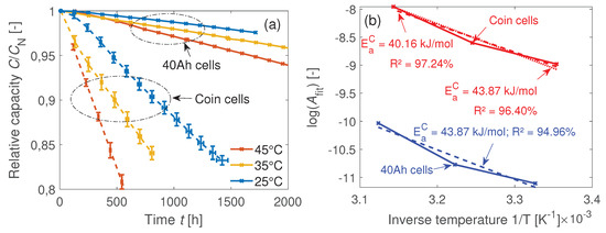
Figure 7.
(a) Relative capacity during cyclic aging of the 40 Ah cells and the coin cells. The temperatures measured at the surfaces of the coin cells during cycling are identical to the set temperatures of the climate chambers C. The averaged surface temperatures of the 40 Ah cells during cycling are C. (b) Temperature-dependent reaction rates derived from the fit functions. The corresponding activation energies of the capacity degradation are the same for both cell types with terms of the measurement uncertainty, which means a similar temperature-dependent degradation mechanism.

Table 6.
Slope factor from the fit functions. The boundary conditions are and . Furthermore, the goodness of fit is listed based on the number of data points taken into account.
The averaged negative slopes from Figure 7a are assumed as proportional to the respective aging reaction rates
with and as the reaction rate constant and pre-exponential factor. Based on this, the activation energy of the capacity degradation can be calculated. As it can be seen in Figure 7b, the activation energies are the same for both cell types regarding the measurement uncertainty which means a similar temperature-dependent degradation mechanism.
4.3.2. Impedance
The following impedance comparison in Figure 8a–d is based on the relative changes in resistance beginning with the 50th cycle. The relative developments of the internal cell resistances at and C are shown in Figure 8a,c. The significant increase in internal resistance over time at C and the only slight increase at C of the 40 Ah cells are in accordance with [53]. At , the polarization resistance in [53], similar to our definition of , remained constant until 500 cycles, whereas the ohmic resistance from EIS in [53] showed a clear trend toward increasing values. This different behavior between and was also observed in this investigation for the 40 Ah cells in Figure 8a. According to [53], the significant increase in internal resistance for the 40 Ah cell at C is linked to the consumption of electrolyte and to an increased separator resistance.
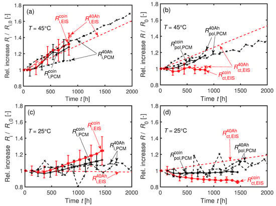
Figure 8.
Developments of the (a,c) internal resistances, the (b,d) charge transfer, and polarization resistances during cyclic aging at 1C for the 40 Ah cells and the averaged coin cells at (a,b) C and at (c,d) C. Each averaged coin cell curve consists of at least four cells. For better clarity, the error bars are only shown every 100 cycles.
The resistance is defined as the linearized voltage decrease within after applying a 1C pulse current. This is why diffusion should affect , contrary to . This explains the difference in development of both resistances and in Figure 8b for both cell types at . An increase of the diffusion resistance, which is part of , can reveal morphological changes of the active material [60]. In contrast, an increase in indicates pure LLI [60]. The polarization resistances of both cell types significantly increase at C after , whereas it stays approximately constant at C as seen in Figure 8d. Thus, LAM is assumed to appear in the 40 Ah cell as well as in the coin cells while aging at C.
4.3.3. Anode Potentials
The trend of maximum anode potentials of the coin cells in Figure 9a can be separated into two parts. The first part is characterized by a strong increase of over the decreasing capacity while there is a slight, roughly linear increase in over the capacity in the second part. The first part is clearly visible in particular at low temperatures. The shift in toward higher values is less intense at C. The second part is visible for all investigated temperatures. The deviation in increases toward higher temperatures. Loss of lithium inventory or LLI + can cause an increase of [6]. Hence, the higher rate of change with increasing temperature might result from an increasing proportion of LLI + LAM. Loss of positive material LAM causes an opposite trend lowering [6]. Therefore, LAM can be excluded from being the sole aging mechanism.

Figure 9.
(a) Maximum and (b) minimum anode potentials of the C/3 capacity reference cycles during cyclic aging. The data points at 0 cycles are missing for the C cells.
The minimum anode potentials in Figure 9b stay approximately constant which means that is not the major aging mechanism. The minimal anode potentials stay always above . Thus, the contribution of Li-plating on the SOH is not significant. Hence, LLI contributes significantly to the for all three temperatures.
4.3.4. Incremental Capacity Analysis
Figure 10a–h depict the trend in IC at C. The trends of all three FOIs are comparable between the 40 Ah cells and the coin cells. The IC at FOI0 increases strongly for both cell types within the first 100 cycles, as seen in Figure 10c,f. After 100 cycles, the IC values remain approximately constant. An increase in the IC value at FOI0 can only be explained by dominating LLI (see Table 1). This development fits with the strong increase in in Figure 9a at the beginning. A not yet fully formed SEI might be an explanation for the high LLI during the first cycles. The significant drops in the peak heights at FOI1 and FOI2 in combination with a small change of the position of FOI2 towards higher voltages speaks again for LLI (see Table 1).
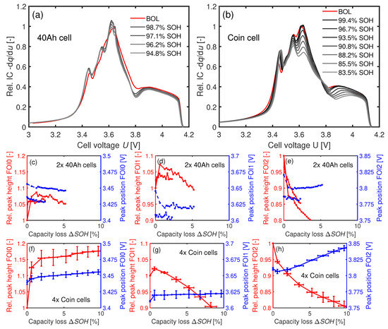
Figure 10.
IC analysis of the 40 Ah cells in (a,c,d,e) and of the coin cells in (b,f,g,h) at C. (a,b) IC curves scaled to the respective maximum peak heights of FOI1 at BOL. c–h: Development of the FOIs depending on the loss of capacity .
4.3.5. Differential Voltage Analysis
Figure 11a,c shows the DV curves of a 40 Ah and a coin cell aged at C. The corresponding relative changes in the phase widths are presented in Figure 11b,d. The phase widths of both cell types drop faster than or over which indicates LLI. However, there is also a decrease in and . A reduction of all phase widths corresponds to LAM [6,25]. Therefore, the combinations LLI + LAM or LLI + LAM + LAM seem plausible [6].
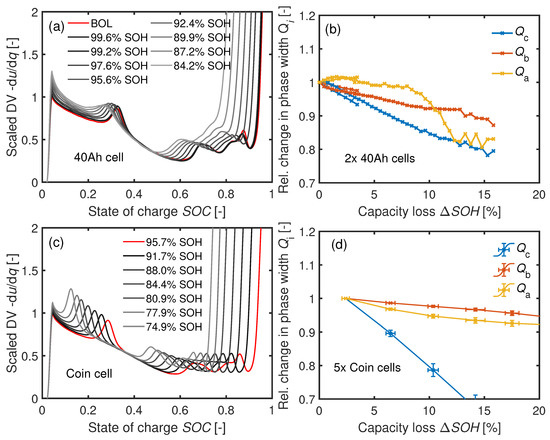
Figure 11.
(a) DV of a cyclically aged 40 Ah cell at and (b) the 40 Ah cells’ corresponding relative phase widths. (c) DV of a cyclically aged coin cell at . (d) Development of the phase widths of five coin cells at .
The DV curves at C are visible in Figure 12a,c. The corresponding relative phase widths and in Figure 12b,d stay roughly constant after the initial capacity loss. The trend of the values reveals LLI as the aging mechanism, as previously shown in the IC analysis.
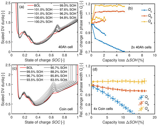
Figure 12.
(a) DV of a cyclically aged 40 Ah cell at C and (b) the 40 Ah cells’ relative phase width development. (c) DV of a cyclically aged coin cell at C with (d) the corresponding trend of the phase widths of four aged coin cells.
The initial electrode balancing at BOL and LLI can be responsible for the initial increase in . In the coin cells, the capacity of the anode is slightly larger than the capacity of the cathode with . The planar electrode ratio between the electrodes is for the 40 Ah cell (see Table 2) and thus larger than for the coin cells with . Hence, the effective loading ratio is around for the 40 Ah cell. The anode overhang in the original cells may cause part of the anode capacity (GR stages (III)→(IV)) to not be fully discharged. The resulting potential shift between the electrodes caused by LLI makes this region accessible, as confirmed by the measurements: The relative phase widths increase within the first 50 cycles for both cell types.
A qualitative comparison of the DV curves of a 40 Ah cell and a coin cell is performed in Figure 13a after reaching similar SOHs. The curves are scaled to a local maximum in y direction and by their adjusted SOCs after aging in x direction. The changes in the DV values in terms of the respective BOL values are depicted in Figure 13b. The qualitative shapes and the changes in DV are similar for the 40 Ah and the coin cells. This comparable development in DV indicates the same basic aging mechanisms in both cell types.
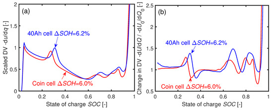
Figure 13.
(a) Normed DVs of a 40 Ah cell and a coin cell cycled at C after similar loss of capacity. (b) Relative change to the DV of the respective cells in comparison to BOL . The coin cell was cycled 150 times and the 40 Ah cell 1200 times to reach the respective .
4.3.6. Summary
Table 7 summarizes the aging mechanism indications resulting from using the characterization methods. The cyclic aging behavior of the investigated 40 Ah pouch cells is reproducible at coin cell level. At the lowest temperature investigated, C, LLI is the main aging mechanism. In case of C, a combination of LLI + LAM + LAM with a strong proportion of LLI is probable. The influence of LAM further increased at C. In summary, the main aging mechanism is LLI when cycling the cells with 1C. In addition, aging due to LAM becomes more relevant with increasing temperature. These results fit into the literature: Although LLI is the dominating aging mechanism in NMC111-GR Li-ion cells, traces of LAM are detectable even at room temperature after cyclic aging [61]. The cause of LAM could be the Mn dissolution which intensifies at higher temperatures [62,63]. As a consequence, the movement of the resulting Mn ions to the anode can lead to LAM [5,10]. The incorporation of Mn ions into the SEI changes and amplifies the SEI reaction [23,24].

Table 7.
Indications resulting from the aging analyses to detect the main aging mechanisms of the cells. The "√" symbol represents a strong indication for a specific aging type (LLI, LAM, ...). A "(√)" marks that several but not all factors agree for a specific aging mechanism. If the cell results did not conform to the mechanism, a “x” symbol is used in the table. A “o” symbol means an ambiguous relationship.
5. Anode Overhang
Table 8 presents the results of the two cell groups during formation.

Table 8.
Influence of an anode overhang on the formation of the coin cells assembled. Analysis of the three formation cycles and the first reference cycle during aging procedure. All four cycles are carried out for the same C/3 current rate.
A larger delithiated anode compared to the cathode results in a higher loading ratio . Thus, the maximum and minimum anode potentials are shifted. Since the cell voltage as is controlled during the experiment, a larger delithiated anode at cell assembly leads to a slightly higher cathode potential at the end of charging the asymmetric cells. Additionally, the current density increases at the edge of the cathode due to the anode overhang [36]. However, oxidation of the cathode should not happen in case of an anode overhang [36]. Only in the first cycle is the Coulomb efficiency (CE) of the asymmetric cells significantly lower: the larger anode area leads to a higher LLI to form the SEI, as seen by the lower discharge capacity for the asymmetric cells in Table 8.
The coefficient of variation is slightly higher for the symmetric cells than for the asymmetric cells. This result is contrary to the results of Long et al. [64]. They described a higher reproducibility of building their 2032-type Hohsen coin cells by using a larger anode to avoid misaligned electrodes [64]. The COVs of the two cell subgroups during formation were low (; see Table 8) compared to the in the third cycle of the work in Long et al. [64]. The PAT-Cell from EL-CELL GmbH used in this work enables precisely aligned electrodes even for .
After subtracting the two worst performing cells in each group, the averaged capacity curves cannot be distinguished from each other as seen in Figure 14.
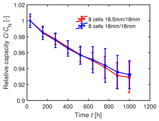
Figure 14.
Averaged relative capacities of the two cell groups during cyclic aging with 1C. For each group, the eight best cells have been selected.
Hence, the capacity degradation of the coin cells is not sensitive to the anode overhang within the range for the specific coin cell structure. The distance between the electrodes, defined by the separator thickness, influences the impact of an anode overhang [36]. In case of an asymmetric assembly (; ), a larger distance between the anode and cathode can enlarge the charging time until Li plating occurs [36]. The inhomogeneity in current density from the edge to the middle of the probe lowers due to the longer pathway of the Li-ions [36]. However, the thicker separator used in the coin cells minimally influences the aging results since we used an extension length of only . Furthermore, the porosity of the coin cell separator is with significantly higher compared to of the original separator [4]. The MacMullin number is directly linked to the porosity [65] [66]. The MacMullin number should be minimized in order to optimize the high rate performance of the cell [66]. The influence of the thicker separator used in the coin cells on the anode overhang results is therefore considered to be low.
6. Leakage
6.1. Dependency On Sealing
The mass transportation of water affects the CE and the cyclic aging behavior of the cells as seen in Figure 15a,b. The use of non-dried PEEK sealing rings leads to a drastic loss in CE during formation and aggravates the capacity loss in comparison with the standard LDPE sealing rings.
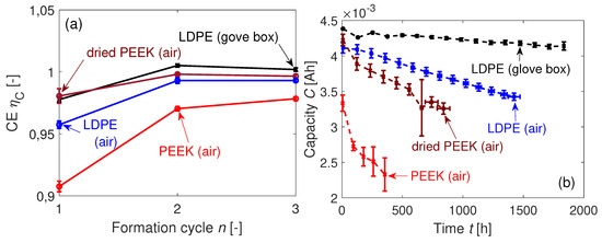
Figure 15.
(a) Coulombic efficiencies CE of the coin cells during formation. (b) Mean capacities of the coin cells at C with the LDPE sealing rings (not dried), PEEK rings (dried and not dried), and the coin cells with the LDPE sealing rings cycled in argon atmosphere (glove box) at room temperature.
The cells with the dried PEEK sealing rings are almost as good in CE during formation as the cells with LDPE sealing rings kept inside the glove box. The CE of the LDPE-sealed cells which are cycled outside the glove box is during the first formation cycle and therefore slightly worse than the LDPE-sealed cells cycled inside the glove box. The drop in capacity during cycling in Figure 15b is significantly affected by the cell sealing. The previously shown aging behavior of the coin cells with LDPE sealing at C from Section 4.3 is added to this plot. Since the temperature inside the glove box is not controlled, the temperature fluctuates, as seen in Figure A1. Three outliers in measured capacity are assigned to temporary temperature fluctuations inside the glove box and are hence neglected for further analysis. The worse cyclic performance of the coin cells with dried PEEK rings compared to the LDPE sealing shows that moisture and not oxygen is mainly responsible for the contamination. This is consistent with a higher diffusion constant for moisture and a lower one for oxygen compared to , as seen in Table 3.
The salt degradation can be described by a second order reaction
with as the solvent-dependent reaction rate constant [41]. An increase in water content c leads to a squared reaction rate (see Equation (11)). The cells with non-dried PEEK sealing rings show this nonlinear dependency in Figure 15b. If is adequately low, Equation (11) can be linearized. Table 9 presents the linear fits of the cyclic aging curves. The factor is highly sensitive to the sealing configuration. The cells aged inside the glove box are losing clearly less capacity than the other coin cell groups cycled at air atmosphere. The goodness of fit of the three cycled cell groups at specified temperature is apparently high with . The lower value of for the cells cycled inside the glove box is probably caused by the fluctuating temperature.

Table 9.
Fit parameters from Figure 15b using the function and the goodness of fit . Data points refer to the number of points used to fit the data. The first data point is neglected for all cell groups.
The faster capacity fade of the cells with dried PEEK sealing rings compared to the cells sealed with LDPE in Figure 15b at the beginning of the cycling might be caused by the initially higher HO concentration difference between the inside and the outside of the coin cells.
The solid state diffusion is linked exponentially to the temperature. Thus, the concentration of moisture inside the coin cell should also show an exponential dependency on linear increasing temperature. However, as seen in Figure 7b, the temperature-dependent capacity losses of the coin cells and the 40 Ah cells are similar. The limited solubility of gas in fluids at higher temperatures might explain why the activation energy hardly changes when cycling the cell material in imperfectly-sealed coin cells.
6.2. EDX Analysis of LDPE-Sealed Coin Cells in an Air Atmosphere
A normally formed SEI contains carbon (C), phosphor (P), fluor (F), and oxygen (O). An indication for salt degradation is an increased F content, as shown by Equations (1) and (2). The concentration of P correlates to the SEI growth in Li-ion cells [29]. Hence, high ratios, measured by EDX (see Section 3.6), point to areas where salt degradation is the main aging mechanism, whereas moderate to low values indicate normal SEI growth.
Figure 16a,b illustrates the change in the F/P ratios in the bulk of the GR electrodes relative to a probes’ BOL values . The initial peak heights of a pristine probe are and for the concentrations of F and P. As shown in Figure 16a, there is no correlation of the capacity loss with the increase in at EOL. In contrast, in the bulk correlates to the measurement time, as seen in Figure 16b. Most likely, this means an increasing impact of the salt degradation in the bulk area by increasing aging time.
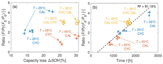
Figure 16.
(a) Development of the F/P ratios on the GR electrodes over the capacity loss of the cell at EOL. (b) Respective values over the time of measurement.
However, due to the fact that does not correlate to the , and due to the similar activation energies between the 40 Ah cell and the coin cells, the salt degradation is a superposed aging effect. Thus, aging the coin cells still reveals the major aging mechanisms of the 40 Ah cells. This superposed aging effect is probably also visible in Table 7 at C: two characterization methods point to LAM in the coin cells. Loss of active material is caused by salt degradation since Mn dissolution is favored by the produced HF [14].
7. Path Dependent Cyclic Aging
The capacity results of this test are summarized in Figure 17a–d. Figure 17a,b disproves the hypothesis of Equation (3) and instead reveals a path dependency
for both cell types. There is a short increase in capacity when changing from calendar to cyclic aging, whereas in the opposite direction the C/3 capacity is dropping instantaneously. The sudden increases in in Figure 17c,d after calendar aging (CAL CYC) indicates a temporary recovery effect of Li during the first cycles for both cell types. In contrast, the phase widths in the opposite mode (CYC CAL) decrease immediately after changing the mode from CYC to CAL.
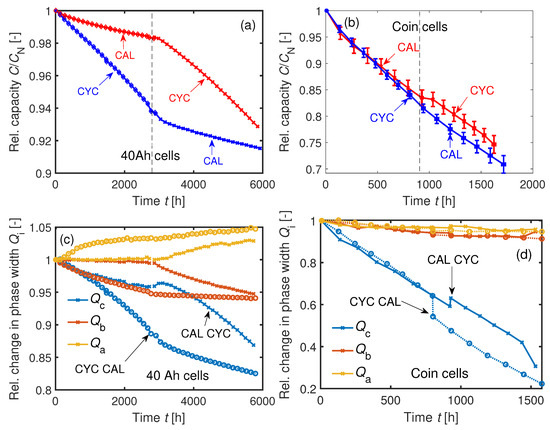
Figure 17.
(a) Aging of two 40 Ah cells at C. One cell was calendrically aged before cyclic aging and vice versa. (b) Sequentially conducted cyclic and calendar aging (CYC CAL) and vice versa (CAL CYC) of four averaged coin cells at C. (c) Changes in the phase widths of the two 40 Ah cells. (d) Changes in the phase widths of the averaged coin cells. Temporary increase of after calendar aging.
The reason for this temporary recovery effect may be explained by the inhomogeneous lithiation in the GR electrodes: Concentration gradients in lithiation are balanced during relaxation periods [67]. In general, electrode particles are unevenly distributed in the electrode. Some particles are in passive areas—for instance, particles in the anode overhang or particles connected to adjacent particles but not directly in contact with electrolyte—which means a lower current density of Li-ions at the particle interface due to higher over-potentials. Diffusion and migration processes compensate for the inhomogeneous lithiation over time. Relatively long diffusion times are needed to distribute the charges equally. The 40 Ah cells had an initial SOC of about 16% after shipping. It is assumed that the cells are homogeneously lithiated at BOL. Then, while cyclic aging at 1C, the Li stored in the passive electrode particles is not or is less-so electrochemically active. The cycle test procedure, as introduced in Section 3.5, includes a break of at 0% SOC after each cycles to cool down the 40 Ah cell for the C/3 capacity test. This ensures similar temperatures between the 40 Ah cells and the coin cells and between the cyclic and calendar aging modes (mean 40 Ah cell temperatures during C/3 capacity tests at the set temperature C: C; C). The LLI during cycling causes concentration gradients in Li distribution between active and passive particles. When the cell’s SOC is held at for after cyclic aging, the remaining higher concentration of Li-ions in the passive areas causes a flow of Li-ions to homogenize the electrode parts. This migration is relatively high at low SOCs due to the big differences of the GR open-circuit potential at low SOCs [68]. This means a consumption of Li-ions from the passive areas during the cyclic aging procedure carried out in this work.
There is no need for such a relaxation period for the calendar aging procedure. The cells are immediately charged with C/3 after discharging with C/3 to 0% SOC. Between each C/3 reference cycle, the cells are aged for five days at . These five days are not sufficient to homogenize the Li distribution. It takes approximately 400 days at to balance the electrode at a SOC of 42% of a prismatic 25 Ah NMC111-GR Li-ion cell [38]. The Li stored in the passive areas during and after calendar aging is then released when changing to cyclic aging mode. Eddahech et al. report a similar recovery effect of the cell capacity after cyclic aging due to an enhanced movement of charge carriers [69].
The cell impedances are also dependent on the aging direction, as seen in Table 10. Thus, Equation (12) is also valid for the impedance increase of both the 40 Ah cells and the coin cells.

Table 10.
Development of the cell resistances and and of the double-layer capacitance based on EIS measurements of the 40 Ah cells and the coin cells after sequential calendar and cyclic aging (CAL CYC) and vice versa (CYC CAL). Inc: increase.
The time-dependent developments of the normed resistances are illustrated in Figure 18. The polarization resistance increases more strongly for CYC CAL compared to CAL CYC. In this case, even the absolute values of the coin cells agree with the values of the 40 Ah cells at end of investigation, as seen in Figure 18.
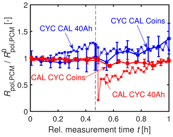
Figure 18.
Relative development of scaled to the initial value at BOL at C. Similar trend of / of the 40 Ah cell and the coin cells.
An explanation for the stronger increase in resistance and the faster capacity fading of the CYC CAL cells is an increased surface area caused by particle cracking at the beginning of the cycling. This assumption is underlined by a stronger decrease of the coin cells’ during cyclic aging () compared to calendar aging () at after the start of the path dependency experiment. The charge transfer resistance
is reciprocally proportional to the surface area S of the exchange current density [70]. The variable z is the number of contributed electrons, F the Faraday constant, and R the gas constant. Thus, for CYC CAL cells, the reaction rate of the calendar aging, which is also dependent on the surface area, may be higher than for the CAL CYC cells due to the previously enlarged surface area during cyclic aging. In addition, the SEI growth of the CAL CYC cells during the calendar aging might reduce the particle cracking caused by the subsequent cyclic aging. The stronger increase in the surface-dependent double-layer capacitance for the CYC CAL original cell (see Table 10) supports this theory. The trends in of the coin cells strongly scatter and therefore do not allow any interpretation.
8. Conclusions
Aging Li-ion cell material in coin cells offers an orders-of-magnitude-lower power requirement per channel to the battery tester. Significantly cheaper testing and simplifications in the safety precautions of the test setup are the consequences.
The preparation procedure used in this work enables building coin cells in a reproducible manner [4]. This work is based on 40 Ah NMC111-graphite Li-ion pouch cells. The original 40 Ah cells and the assembled coin cells (PAT-Cells) are cycled with 1C at three different temperatures . Incremental capacity analysis, differential voltage analysis, maximum/minimum electrode potentials, electrochemical impedance spectroscopy, and pulse current measurements are taken into account to determine the cell aging mechanisms. The results show the same basic aging mechanisms in the coin cells compared to the 40 Ah cells. The almost identical activation energy in cyclic aging between the 40 Ah cells () and the averaged coin cells () confirms this. A trend of increasing loss of active material toward higher temperatures can be detected for both cell types.
The differences in anode overhang do not significantly influence the development of remaining capacity. Post-mortem analyses prove diffusion of moisture into the cell housing. However, the increasing concentration of fluor by measurement time on the graphite anodes of the coin cells is not directly linked to the loss of capacity. Hence, the diffusion of moisture is a superposed aging effect. The temperature-dependent aging mechanisms of the 40 Ah cells are still transferable to coin cell level. Finally, an exemplary path dependency test of both cell types has been carried out. A cyclically and then calendrically aged 40 Ah cell degrades faster compared to a 40 Ah cell, which was calendrically aged before cyclic aging. The observed path dependency of the 40 Ah cell can be transferred to the coin cell format. The developments in capacity and resistance are comparable for both cell types.
This paper serves as orientation for further coin cell preparation work in laboratories. The proposed coin cell aging method proves the possibility of detecting the aging mechanisms happening in cycled commercial Li-ion cells, making it a useful tool to analyze the cell material. However, the gradients in capacity degradation of the coin cells and the original cells are different in this work. Therefore, quantitative aging prediction of commercial Li-ion cells by aging the cell material in coin cells is probably not suitable. Nevertheless, further experiments could reveal the impact of the geometry on aging in Li-ion cells by analyzing coin cells of different sizes.
Author Contributions
Conceptualization, K.P.B. and A.U.S.; methodology, A.U.S.; software, A.U.S. and K.S.; validation, A.U.S., M.H., and A.R.; formal analysis, A.U.S.; investigation, A.U.S.; resources, K.P.B. and M.H.; data curation, A.U.S.; writing—original draft preparation, A.U.S.; writing—review and editing, A.U.S., A.R., K.S., and K.P.B.; visualization, A.U.S.; supervision, K.P.B.; project administration, K.P.B.; funding acquisition, K.P.B. All authors have read and agreed to the published version of the manuscript.
Funding
This research was funded by Robert Bosch GmbH.
Acknowledgments
The authors would like to thank the Robert Bosch GmbH for funding this work (Promotionskolleg EL). Moreover, the authors would like to thank Moritz Kurka and the EL-CELL GmbH for their support and Matthieu Dubarry and the University of Hawaii at Manoa for sharing the ’alawa battery emulation toolbox.
Conflicts of Interest
The authors declare no conflict of interest. The funders had no role in the design of the study; in the collection, analyses, or interpretation of data; in the writing of the manuscript, or in the decision to publish the results.
Appendix A
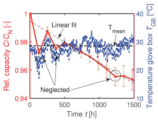
Figure A1.
Temperature-dependent capacitance measurement at room temperature inside the glove box. Allocation of capacity outliers due to a lower ambient temperature.
References
- Mussa, A.S.; Lindbergh, G.; Klett, M.; Gudmundson, P.; Svens, P.; Lindström, R.W. Inhomogeneous active layer contact loss in a cycled prismatic lithium-ion cell caused by the jelly-roll curvature. J. Energy Storage 2018, 20, 213–217. [Google Scholar] [CrossRef]
- Erhard, S.V.; Osswald, P.J.; Keil, P.; Höffer, E.; Haug, M.; Noel, A.; Wilhelm, J.; Rieger, B.; Schmidt, K.; Kosch, S.; et al. Simulation and Measurement of the Current Density Distribution in Lithium-Ion Batteries by a Multi-Tab Cell Approach. J. Electrochem. Soc. 2017, 164, A6324–A6333. [Google Scholar] [CrossRef]
- Kosch, S.; Rheinfeld, A.; Erhard, S.V.; Jossen, A. An extended polarization model to study the influence of current collector geometry of large-format lithium-ion pouch cells. J. Power Sources 2017, 342, 666–676. [Google Scholar] [CrossRef]
- Schmid, A.U.; Kurka, M.; Birke, K.P. Reproducibility of Li-ion cell reassembling processes and their influence on coin cell aging. J. Energy Storage 2019, 24, 100732. [Google Scholar] [CrossRef]
- Vetter, J.; Novák, P.; Wagner, M.R.; Veit, C.; Möller, K.C.; Besenhard, J.O.; Winter, M.; Wohlfahrt-Mehrens, M.; Vogler, C.; Hammouche, A. Ageing mechanisms in lithium-ion batteries. J. Power Sources 2005, 147, 269–281. [Google Scholar] [CrossRef]
- Birkl, C.R.; Roberts, M.R.; McTurk, E.; Bruce, P.G.; Howey, D.A. Degradation diagnostics for lithium ion cells. J. Power Sources 2017, 341, 373–386. [Google Scholar] [CrossRef]
- Dolotko, O.; Senyshyn, A.; Mühlbauer, M.; Nikolowski, K.; Ehrenberg, H. Understanding structural changes in NMC Li-ion cells by in situ neutron diffraction. J. Power Sources 2014, 255, 197–203. [Google Scholar] [CrossRef]
- Shinova, E.; Stoyanova, R.; Zhecheva, E.; Ortiz, G.; Lavela, P.; Tirado, J. Cationic distribution and electrochemical performance of LiCo1/3Ni1/3Mn1/3O2 electrodes for lithium-ion batteries. Solid State Ionics 2008, 179, 2198–2208. [Google Scholar] [CrossRef]
- Warnecke, A.J. Degradation Mechanisms in NMC-Based Lithium-Ion Batteries. Ph.D. Thesis, Veröffentlicht auf dem Publikationsserver der RWTH Aachen University, RWTH Aachen University, Aachen, Germany, 2017. [Google Scholar] [CrossRef]
- Shin, H.; Park, J.; Sastry, A.M.; Lu, W. Degradation of the solid electrolyte interphase induced by the deposition of manganese ions. J. Power Sources 2015, 284, 416–427. [Google Scholar] [CrossRef]
- Xiao, X.; Liu, Z.; Baggetto, L.; Veith, G.M.; More, K.L.; Unocic, R.R. Unraveling manganese dissolution/deposition mechanisms on the negative electrode in lithium ion batteries. Phys. Chem. Chem. Phys. 2014, 16, 10398–10402. [Google Scholar] [CrossRef]
- Aurbach, D. Review of selected electrode-solution interactions which determine the performance of Li and Li ion batteries. J. Power Sources 2000, 89, 206–218. [Google Scholar] [CrossRef]
- Niehoff, P.; Winter, M. Composition and Growth Behavior of the Surface and Electrolyte Decomposition Layer of/on a Commercial Lithium Ion Battery LixNi1/3Mn1/3Co1/3O2 Cathode Determined by Sputter Depth Profile X-ray Photoelectron Spectroscopy. Langmuir 2013, 29, 15813–15821. [Google Scholar] [CrossRef] [PubMed]
- Matsuo, Y.; Kostecki, R.; McLarnon, F. Surface Layer Formation on Thin-Film LiMn2O4 Electrodes at Elevated Temperatures. J. Electrochem. Soc. 2001, 148, A687–A692. [Google Scholar] [CrossRef]
- Broussely, M.; Herreyre, S.; Biensan, P.; Kasztejna, P.; Nechev, K.; Staniewicz, R. Aging mechanism in Li ion cells and calendar life predictions. J. Power Sources 2001, 97, 13–21. [Google Scholar] [CrossRef]
- Pinson, M.B.; Bazant, M.Z. Theory of SEI Formation in Rechargeable Batteries: Capacity Fade, Accelerated Aging and Lifetime Prediction. J. Electrochem. Soc. 2013, 160, A243–A250. [Google Scholar] [CrossRef]
- Kindermann, F.M.; Keil, J.; Frank, A.; Jossen, A. A SEI Modeling Approach Distinguishing between Capacity and Power Fade. J. Electrochem. Soc. 2017, 164, E287–E294. [Google Scholar] [CrossRef]
- Ekström, H.; Lindbergh, G. A Model for Predicting Capacity Fade due to SEI Formation in a Commercial Graphite/LiFePO4 Cell. J. Electrochem. Soc. 2015, 162, A1003–A1007. [Google Scholar] [CrossRef]
- Yang, X.G.; Leng, Y.; Zhang, G.; Ge, S.; Wang, C.Y. Modeling of lithium plating induced aging of lithium-ion batteries: Transition from linear to nonlinear aging. J. Power Sources 2017, 360, 28–40. [Google Scholar] [CrossRef]
- Broussely, M.; Biensan, P.; Bonhomme, F.; Blanchard, P.; Herreyre, S.; Nechev, K.; Staniewicz, R. Main aging mechanisms in Li ion batteries. J. Power Sources 2005, 146, 90–96. [Google Scholar] [CrossRef]
- Waldmann, T.; Hogg, B.I.; Wohlfahrt-Mehrens, M. Li plating as unwanted side reaction in commercial Li-ion cells—A review. J. Power Sources 2018, 384, 107–124. [Google Scholar] [CrossRef]
- Bach, T.C.; Schuster, S.F.; Fleder, E.; Müller, J.; Brand, M.J.; Lorrmann, H.; Jossen, A.; Sextl, G. Nonlinear aging of cylindrical lithium-ion cells linked to heterogeneous compression. J. Energy Storage 2016, 5, 212–223. [Google Scholar] [CrossRef]
- Cho, I.H.; Kim, S.S.; Shin, S.C.; Choi, N.S. Effect of SEI on Capacity Losses of Spinel Lithium Manganese Oxide/Graphite Batteries Stored at 60 °C. Electrochem. Solid-State Lett. 2010, 13, A168–A172. [Google Scholar] [CrossRef]
- Delacourt, C.; Kwong, A.; Liu, X.; Qiao, R.; Yang, W.L.; Lu, P.; Harris, S.J.; Srinivasan, V. Effect of Manganese Contamination on the Solid-Electrolyte-Interphase Properties in Li-Ion Batteries. J. Electrochem. Soc. 2013, 160, A1099–A1107. [Google Scholar] [CrossRef]
- Dubarry, M.; Truchot, C.; Liaw, B.Y. Synthesize battery degradation modes via a diagnostic and prognostic model. J. Power Sources 2012, 219, 204–216. [Google Scholar] [CrossRef]
- Striebel, K.; Shim, J.; Sierra, A.; Yang, H.; Song, X.; Kostecki, R.; McCarthy, K. The development of low cost LiFePO4-based high power lithium-ion batteries. J. Power Sources 2005, 146, 33–38. [Google Scholar] [CrossRef]
- Keil, P.; Schuster, S.F.; Wilhelm, J.; Travi, J.; Hauser, A.; Karl, R.C.; Jossen, A. Calendar Aging of Lithium-Ion Batteries. J. Electrochem. Soc. 2016, 163, A1872–A1880. [Google Scholar] [CrossRef]
- Waldmann, T.; Wilka, M.; Kasper, M.; Fleischhammer, M.; Wohlfahrt-Mehrens, M. Temperature dependent ageing mechanisms in Lithium-ion batteries— A Post-Mortem study. J. Power Sources 2014, 262, 129–135. [Google Scholar] [CrossRef]
- Waldmann, T.; Ghanbari, N.; Kasper, M.; Wohlfahrt-Mehrens, M. Correlations between Electrochemical Data and Results from Post-Mortem Analysis of Aged Lithium-Ion Batteries. J. Electrochem. Soc. 2015, 162, A1500–A1505. [Google Scholar] [CrossRef]
- Dubarry, M.; Devie, A.; Liaw, B.Y. The value of battery diagnostics and prognostics. J. Energy Power Sources 2014, 1, 242–249. [Google Scholar]
- Dubarry, M.; Baure, G.; Anseán, D. Perspective on State of Health determination in Lithium ion batteries. J. Electrochem. Energy Convers. Storage 2019, 1–25. [Google Scholar] [CrossRef]
- Birkl, C.R.; McTurk, E.; Roberts, M.R.; Bruce, P.G.; Howey, D.A. A Parametric Open Circuit Voltage Model for Lithium Ion Batteries. J. Electrochem. Soc. 2015, 162, A2271–A2280. [Google Scholar] [CrossRef]
- Berecibar, M.; Dubarry, M.; Omar, N.; Villarreal, I.; Van Mierlo, J. Degradation mechanism detection for NMC batteries based on Incremental Capacity curves. World Electr. Veh. J. 2016, 8, 350. [Google Scholar] [CrossRef]
- Mussa, A.S. Durability Aspects of Fast Charging, Mechanical Constraint, and Inhomogeneity in Lithium-Ion Batteries. Ph.D. Thesis, KTH The Royal Institute of Technology, Stockholm, Sweden, 2018. [Google Scholar]
- Son, B.; Ryou, M.H.; Choi, J.; Kim, S.H.; Ko, J.M.; Lee, Y.M. Effect of cathode/anode area ratio on electrochemical performance of lithium-ion batteries. J. Power Sources 2013, 243, 641–647. [Google Scholar] [CrossRef]
- Tang, M.; Albertus, P.; Newman, J. Two-Dimensional Modeling of Lithium Deposition during Cell Charging. J. Electrochem. Soc. 2009, 156, A390–A399. [Google Scholar] [CrossRef]
- Wilhelm, J.; Seidlmayer, S.; Keil, P.; Schuster, J.; Kriele, A.; Gilles, R.; Jossen, A. Cycling capacity recovery effect: A coulombic efficiency and post-mortem study. J. Power Sources 2017, 365, 327–338. [Google Scholar] [CrossRef]
- Lewerenz, M.; Fuchs, G.; Becker, L.; Sauer, D.U. Irreversible calendar aging and quantification of the reversible capacity loss caused by anode overhang. J. Energy Storage 2018, 18, 149–159. [Google Scholar] [CrossRef]
- Burns, J.C.; Sinha, N.N.; Jain, G.; Ye, H.; VanElzen, C.M.; Scott, E.; Xiao, A.; Lamanna, W.M.; Dahn, J.R. The Impact of Intentionally Added Water to the Electrolyte of Li-Ion Cells: II. Cells with Lithium Titanate Negative Electrodes. J. Electrochem. Soc. 2014, 161, A247–A255. [Google Scholar] [CrossRef]
- Burns, J.C.; Sinha, N.N.; Jain, G.; Ye, H.; VanElzen, C.M.; Scott, E.; Xiao, A.; Lamanna, W.M.; Dahn, J.R. The Impact of Intentionally Added Water to the Electrolyte of Li-ion Cells: I. Cells with Graphite Negative Electrodes. J. Electrochem. Soc. 2013, 160, A2281–A2287. [Google Scholar] [CrossRef]
- Kawamura, T.; Okada, S.; Yamaki, J. Decomposition reaction of LiPF6-based electrolytes for lithium ion cells. J. Power Sources 2006, 156, 547–554. [Google Scholar] [CrossRef]
- Ein-Eli, Y.; McDevitt, S.; Laura, R. The Superiority of Asymmetric Alkyl Methyl Carbonates. J. Electrochem. Soc. 1998, 145, L1. [Google Scholar] [CrossRef]
- Xu, K. Nonaqueous liquid electrolytes for lithium-based rechargeable batteries. Chem. Rev. 2004, 104, 4303–4417. [Google Scholar] [CrossRef]
- Su, L.; Zhang, J.; Huang, J.; Ge, H.; Li, Z.; Xie, F.; Liaw, B.Y. Path dependence of lithium ion cells aging under storage conditions. J. Power Sources 2016, 315, 35–46. [Google Scholar] [CrossRef]
- Hahn, S.L.; Storch, M.; Swaminathan, R.; Obry, B.; Bandlow, J.; Birke, K.P. Quantitative validation of calendar aging models for lithium-ion batteries. J. Power Sources 2018, 400, 402–414. [Google Scholar] [CrossRef]
- Li, Y.; Abdel-Monem, M.; Gopalakrishnan, R.; Berecibar, M.; Nanini-Maury, E.; Omar, N.; van den Bossche, P.; Van Mierlo, J. A quick on-line state of health estimation method for Li-ion battery with incremental capacity curves processed by Gaussian filter. J. Power Sources 2018, 373, 40–53. [Google Scholar] [CrossRef]
- Winter, M.; Besenhard, J.O. Lithiated Carbons. In Handbook of Battery Materials; Daniel, C., Besenhard, J.O., Eds.; Wiley-VCH Verlag GmbH & Co. KGaA: Weinheim, Germany, 2011; Chapter 15; pp. 433–478. [Google Scholar]
- Ohzuku, T.; Iwakoshi, Y.; Sawai, K. Formation of lithium-graphite intercalation compounds in nonaqueous electrolytes and their application as a negative electrode for a lithium ion (shuttlecock) cell. J. Electrochem. Soc. 1993, 140, 2490–2498. [Google Scholar] [CrossRef]
- Rodrigues, S.; Munichandraiah, N.; Shukla, A.K. AC impedance and state-of-charge analysis of a sealed lithium-ion rechargeable battery. J. Solid State Electrochem. 1999, 3, 397–405. [Google Scholar] [CrossRef]
- Waag, W.; Käbitz, S.; Sauer, D.U. Experimental investigation of the lithium-ion battery impedance characteristic at various conditions and aging states and its influence on the application. Appl. Energy 2013, 102, 885–897. [Google Scholar] [CrossRef]
- Schmid, A.; Lindel, L.; Birke, K. Capacitive effects in Li1-xNi0.3Co0.3Mn0.3O2-LixCy Li-ion cells. J. Energy Storage 2018, 18. [Google Scholar] [CrossRef]
- Ecker, M.; Sabet, P.S.; Sauer, D.U. Influence of operational condition on lithium plating for commercial lithium-ion batteries–Electrochemical experiments and post-mortem-analysis. Appl. Energy 2017, 206, 934–946. [Google Scholar] [CrossRef]
- Jalkanen, K.; Karppinen, J.; Skogström, L.; Laurila, T.; Nisula, M.; Vuorilehto, K. Cycle aging of commercial NMC/graphite pouch cells at different temperatures. Appl. Energy 2015, 154, 160–172. [Google Scholar] [CrossRef]
- EL-CELL GmbH. PAT-Cell. Our Electrochemical Test Cell for Two- and Three-Electrode Testing. 2018. Available online: https://el-cell.com/products/test-cells/standard-test-cells/pat-cell (accessed on 20 August 2018).
- Zhang, S.; Jow, T.; Amine, K.; Henriksen, G. LiPF6-EC-EMC electrolyte for Li-ion battery. J. Power Sources 2002, 107, 18–23. [Google Scholar] [CrossRef]
- Keller, P.E.; Kouzes, R. Water Vapor Permeation in Plastics; Pacific Northwest National Laboratory: Richland, WA, USA, 2003. [Google Scholar] [CrossRef]
- Monson, L.; Moon, S.I.; Extrand, C.W. Permeation resistance of poly(ether ether ketone) to hydrogen, nitrogen, and oxygen gases. J. Appl. Polym. Sci. 2013, 127, 1637–1642. [Google Scholar] [CrossRef]
- Grayson, M.A.; Wolf, C.J. The solubility and diffusion of water in poly(aryl-ether-ether-ketone) (PEEK). J. Polym. Sci. Part B: Polym. Phys. 1987, 25, 31–41. [Google Scholar] [CrossRef]
- Armstrong, R.D.; Todd, M. Interfacial electrochemistry. In Solid State Electrochemistry; Bruce, P.G., Ed.; Cambridge University Press: Cambridge, UK, 1995; Volume 2, pp. 264–291. [Google Scholar]
- Pastor-Fernández, C.; Uddin, K.; Chouchelamane, G.H.; Widanage, W.D.; Marco, J. A Comparison between Electrochemical Impedance Spectroscopy and Incremental Capacity-Differential Voltage as Li-ion Diagnostic Techniques to Identify and Quantify the Effects of Degradation Modes within Battery Management Systems. J. Power Sources 2017, 360, 301–318. [Google Scholar] [CrossRef]
- Stiaszny, B.; Ziegler, J.C.; Krauß, E.E.; Schmidt, J.P.; Ivers-Tiffée, E. Electrochemical characterization and post-mortem analysis of aged LiMn 2O4-Li(Ni0.5Mn0.3Co 0.2)O2/graphite lithium ion batteries. Part I: Cycle aging. J. Power Sources 2014, 251, 439–450. [Google Scholar] [CrossRef]
- Kim, D.; Park, S.; Chae, O.B.; Ryu, J.H.; Kim, Y.U.; Yin, R.Z.; Oh, S.M. Re-Deposition of Manganese Species on Spinel LiMn2O4 Electrode after Mn Dissolution. J. Electrochem. Soc. 2012, 159, A193–A197. [Google Scholar] [CrossRef]
- Buchberger, I.; Seidlmayer, S.; Pokharel, A.; Piana, M.; Hattendorff, J.; Kudejova, P.; Gilles, R.; Gasteiger, H.A. Aging Analysis of Graphite/LiNi1/3Mn1/3Co1/3O2 Cells Using XRD, PGAA, and AC Impedance. J. Electrochem. Soc. 2015, 162, A2737–A2746. [Google Scholar] [CrossRef]
- Long, B.R.; Rinaldo, S.G.; Gallagher, K.G.; Dees, D.W.; Trask, S.E.; Polzin, B.J.; Jansen, A.N.; Abraham, D.P.; Bloom, I.; Bareño, J.; et al. Enabling High-Energy, High-Voltage Lithium-Ion Cells: Standardization of Coin-Cell Assembly, Electrochemical Testing, and Evaluation of Full Cells. J. Electrochem. Soc. 2016, 163, A2999–A3009. [Google Scholar] [CrossRef]
- Landesfeind, J.; Hattendorff, J.; Ehrl, A.; Wall, W.A.; Gasteiger, H.A. Tortuosity Determination of Battery Electrodes and Separators by Impedance Spectroscopy. J. Electrochem. Soc. 2016, 163, A1373–A1387. [Google Scholar] [CrossRef]
- Djian, D.; Alloin, F.; Martinet, S.; Lignier, H.; Sanchez, J. Lithium-ion batteries with high charge rate capacity: Influence of the porous separator. J. Power Sources 2007, 172, 416–421. [Google Scholar] [CrossRef]
- Fuller, T.F.; Doyle, M.; Newman, J. Relaxation Phenomena in Lithium-Ion-Insertion Cells. J. Electrochem. Soc. 1994, 141, 982–990. [Google Scholar] [CrossRef]
- Lewerenz, M.; Münnix, J.; Schmalstieg, J.; Käbitz, S.; Knips, M.; Sauer, D.U. Systematic aging of commercial LiFePO4|Graphite cylindrical cells including a theory explaining rise of capacity during aging. J. Power Sources 2017, 345, 254–263. [Google Scholar] [CrossRef]
- Eddahech, A.; Briat, O.; Vinassa, J.M. Lithium-ion battery performance improvement based on capacity recovery exploitation. Electrochim. Acta 2013, 114, 750–757. [Google Scholar] [CrossRef]
- Bard, A.; Faulkner, L. Electrochemical Methods: Fundamentals and Applications; Wiley: New York, NY, USA, 1980; Volume 2. [Google Scholar]
© 2020 by the authors. Licensee MDPI, Basel, Switzerland. This article is an open access article distributed under the terms and conditions of the Creative Commons Attribution (CC BY) license (http://creativecommons.org/licenses/by/4.0/).