Article

A Newly Designed Modular ZnBr2 Single Cell Structure

1
College of Automation, Nanjing University of Posts and Telecommunications, Nanjing 210003, China
2
NARI Technology Co., Ltd., Nanjing 211000, China
*
Author to whom correspondence should be addressed.
Batteries 2020, 6(2), 27; https://doi.org/10.3390/batteries6020027
Submission received: 18 February 2020 / Revised: 26 April 2020 / Accepted: 28 April 2020 / Published: 4 May 2020

Abstract

:
We describe a ZnBr2 single cell which has a highly modular symmetrical structure. With designed polyethylene shell frames, membrane frame and composite titanium-carbon felt electrodes, it has a higher energy density and is more flexible compared with traditional flow batteries. We repeatedly tested its performance, which showed good tightness, high reliability and a high energy efficiency of 75%. Due to the special symmetrical structure and modular design, it is easy to assemble and disassemble, which makes it suitable as a test platform for electrodes, membranes and electrolyte performance testing. The designed modular flow cell has low cost and high energy density, and can provide good guidance for flow battery research.

1. Introduction

Energy storage is the key technology to promote the replacement of traditional energy types and closely affects the development of new energy technology, making how to build efficient, reliable and cost-effective large-scale energy storage systems critical for societal development [1,2]. Due to flow batteries’ long cycle life, deep discharge depth, high safety, low cost and high energy efficiency, they are considered an important long-term energy storage mode [3]. Theoretically, the flow battery capacity is only determined by the volume of the electrolyte stored in the tanks. According to the different active substances, flow batteries can be divided into vanadium, zinc/bromine, sodium polysulfide/bromine, iron/chromium, etc. Among of them, the vanadium redox battery (VRB) and zinc-bromine flow battery (ZBFB) are two of the most widely used flow batteries. Different from VRB, ZBFB has higher energy density, lower building cost and better environmentally friendliness [4,5,6].
The ZBFB system is based on the deposition of zinc at the negative electrode and bromine evolution at the positive electrode and consists of the cell, electrolyte tanks and pumps [7]. As shown in Figure 1, different from conventional batteries, the active materials of ZBFB at both electrodes are the same ZnBr2 solution that is stored in two external tanks and separately circulated inside the flow cell by two magnetic pumps [4]. In order to reduce the self-discharge inside the flow cell, the ZnBr2 solutions inside two half-cells are separated by an exchange membrane to prevent the two solutions from mixing. The basic electrochemical reactions of a ZBFB are as follows [8]:
Anode   reaction :   Z n 2 + + 2 e Zn
Cathode   reaction :   2 B r B r 2 + 2 e
Net   cell   reaction :   Z n 2 + + 2 B r Zn + B r 2
During the charging process, zinc ions are reduced to zinc particles and deposit on the surface of the anode electrode. At the same time, the bromine ions converted into bromine by the oxidation reaction will be captured by the ligand complex forming an oily complex precipitate and are stored at the bottom of the positive electrode electrolyte. During the discharging process, in contrast to the charging process, zinc and bromide ions are generated at the negative and positive electrodes, respectively.
Although ZBFB systems have been studied for a long time, the problems of charge-discharge efficiency and battery charge are still not solved adequately [9]. In order to check the performance of electrodes, membranes and electrolytes, we have to design and build many single cells which is complicated and a heavy waste. How to design one flexible flow cell structure that has good flexibility, high space utilization rate and great fluid tightness is still a research focus for ZBFB systems.
In this paper, we describe a modular ZnBr2 single cell structure, which adopts a symmetrical structure with a membrane sandwiched between two shell frames [10]. The symmetrical structure and modular design make it flexible for assembly and disassembly, so it is suitable to be use as a test platform for electrodes, membranes and electrolyte performance testing.

2. Experimental

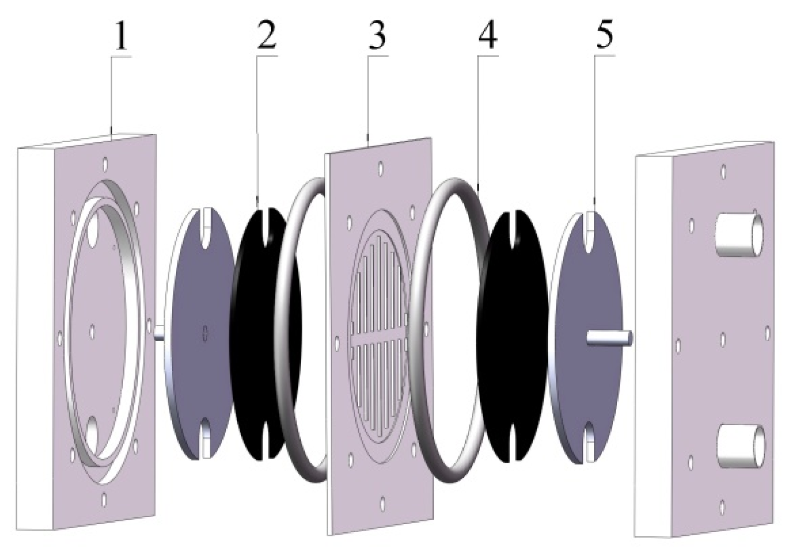
2.1. Flow Frame ZnBr2 Single Cell

The ZnBr2 single cell system includes a cell, three magnetic pumps, and two electrolyte tanks. The most important part is the cell, which is the core component of the ZnBr2 cell system. A schematic view of the cell is shown in Figure 2.
The cell is composed of two symmetrical polyethylene shell frames, two composite electrodes and a membrane frame, which are squeezed together in series through two fluorocarbon O-rings and six stainless steel bolts. The positive and negative electrodes are both composed by titanium foam and carbon felt [11]. The whole structure is symmetrical and simple [12], it is easy to assemble or disassemble, which makes it suitable to be used as a standard test platform for performance testing of electrodes, membranes and electrolytes [13,14].

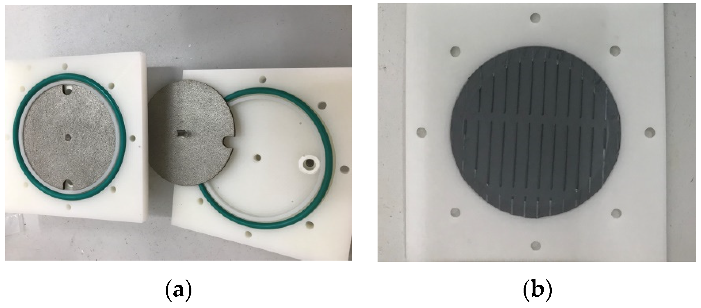
2.2. Electrode and Membrane Frame

As shown in Figure 3a, the titanium foam electrode which has a titanium terminal at the center is manufactured by 3D printing. The calculated active area of the electrode is 24.72 cm2. Compared with traditional graphite electrodes, titanium foam electrodes have good electrical conductivity, good rigidity and can be machined into any desired shape [15]. With the help of carbon felt between the titanium foam electrode and exchange membrane, the internal resistance inside the flow cell decreases because carbon felt has a better conductivity than the electrolyte. Most importantly, the carbon felt can provide more active reaction sites. Furthermore, the titanium foam electrode integrate the electrode and current collecting column together, so it’s not necessary to use a separate current collecting column that can reduce the contact resistance between the electrode and the collecting column [16]. The role of the membrane is to prevent the solutions from the two half-cells from mixing, which can reduce the self-discharge of the ZBFB system. We designed a membrane frame and built it by using one polyethylene plate as shown in Figure 3b. The membrane we used in this paper is a zbmm-600 microporous exchange membrane produced by Beijing Zbest Power Technology Co., Ltd. (Beijing, China), which has a pore size of less than 10 nm. The designed membrane frame has the advantage of low cost and strong water absorption.
A rib-like microporous exchange membrane is fixed at the center of the membrane frame by laser welding technology. After hundreds of assembly and performance cycling tests, besides its good fluid sealing performance, the designed structure has another two distinct advantages: First, the channels on the microporous exchange membrane can strengthen the rigidity of the structure and prevent the deformation of the membrane caused by the high fluid flow rate. Second, the channels can increase the turbulence in the cell and the ion reaction area [17].

2.3. Electrolyte Configuration

The electrolyte configuration is also very important for a ZBFB system, which is related with many problems during charging, such as electrode corrosion, high self-discharge rate, zinc dendrite formation, etc. [18] According to [19], we set our ZnBr2 solution molar concentration as 2 mol/L, which has good conductivity and lower corrosion rate, and the total volume of the electrolyte is 1 L. In order to prevent the bromine from transferring into the zinc half-cell, we chose methylethylmorpholinium bromide (MEM) as our complexing agent. Zinc bromide (ZnBr2), potassium chloride (KCl) are both from NARI Technology Co., Ltd. (Nanjing, China). 2 M ZnBr2 in deionized water was used as electrolyte, 0.5 M MEM and KCl were added into the solution to adjust the desired concentration [20].

3. Results and Discussion

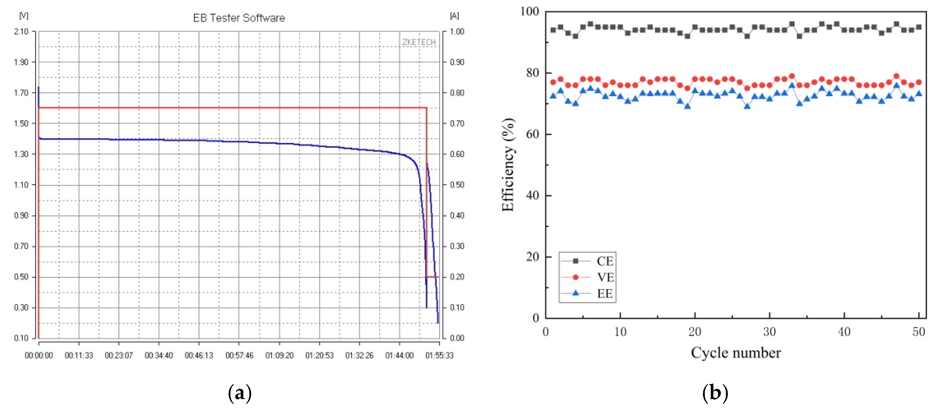
3.1. Pre-Preparation of the System Cycle

Figure 4 shows a photo of our modular ZnBr2 single cell system. Before the performance test, we first fill both reservoirs with some deionized water and turn on all the magnetic pumps (MP-6R, Shanghai Xinxishan Co., Ltd., Shanghai, China) at constant room temperature to clean the whole system and check for leaks. According to Sun’s research results for the flow rate in ZBFB system, 100 mL/min is a better fluid flow rate which can hinder excessive production of zinc dendrites [21], so we set our fluid flow rate as 100 mL/min in this paper. After two hours of deionized water circulation, we confirm the single cell’s stability and fluid tightness, then we fill the configured electrolyte into both reservoirs and add more bromine into the positive reservoir to make the bromine concentration around 0.5 mol/L.

3.2. Electrolyte Configuration

Before the first cycle charge-discharge test, it is better to circulate the electrolyte for two hours to completely soak the microporous exchange membrane. After two hours of circulation, we start the efficiency test with our battery capacity tester (EBC-A10+, ZKETECH, Zhuozhi Electronic Technology, Co., Ltd., Shanghai, China). For the charging process, using constant current charging mode, we set the charging current density value at about 30 mA/cm2. By changing the charging time, we test the efficiency under different cell capacities. At the end of every charge cycle, we set one minute relaxation time for the single cell to reach a stable state and then collect the open circuit voltage. For the discharging process, we also use constant discharging mode and set the first stage discharge current as 0.75 A and end voltage as 0.3 V. When the cell’s voltage is lower than 0.3 V, the first stage discharging process stops and the terminal voltage returns to a higher value. Then we start the second stage discharging process, in which we set discharge current as 0.2 A and end voltage as 0.3 V for further deep discharge tests, and that cycle repeats.
As shown in Figure 5, we tested a series of capacities of the single cell from 0.5 Ah to 4 Ah at room temperature. For every capacity, we perform three charge-discharge tests and calculate the average. As we know, energy efficiency characterizes the degree of recovery of stored energy, while voltage efficiency (VE) reflects the internal resistance of the cell, moreover, a high Coulomb efficiency (CE), which is related with electrodes’ reversibility during the charge-discharge reaction process, indicates that the composite titanium-carbon felt electrodes have high conductivity and stability [22,23].
The equations for calculating the battery’s efficiency are as follows:
EE :   η E = E discharge E charge × 100 %
CE :   η Q = A discharge A charge × 100 %
VE :   η V = EE CE × 100 %
We calculate the EE, CE and VE of ZnBr2 single cell under different charging capacities. The high Coulomb efficiency indicates that the flow cell has a lower self-discharge rate. Because of our use of a composite electrode, the internal resistance becomes smaller which is reflected in the VE results. With a fluid flow rate of 100 mL/min and a current density of 30 mA/cm2, the EE of our flow cell can reach up to 75% at room temperature. Compared with Li’s ZBFB stack in a single cell module [24], which has traditional structural design and a Nafion/PTFE composite membrane, our cell structure has lower cost, smaller size and higher current density.
Laboratory-scale monolithic flow batteries typically use 50 cycles of constant current cycling to test their stability [25,26]. In order to get a more intuitive comparison, we perform a 50-cycle battery charge-discharge cycle test with a constant current density of 30 mA/cm2 as described in this paper. As shown in Figure 6, we perform a cycle test at 1.5 Ah of the battery. The total amount of released electricity is the cell’s capacity when it reaches the desired voltage, defined as:
Cd = IdTd
where Cd, Id and Td represent the discharging capacity, current, and duration of the discharge process, respectively [27]. In this paper, Id of the cell was set as 0.75 A, Td of the cell is 2 h. Therefore, the formulas of the battery energy (Ed.) and energy density (w) can be expressed as follows:
Ed = VdCd
w = E d m
where Vd represents the discharging voltage, which for the single cell is 1.37 V, and the actual reaction mass of the battery is about 50.8 g. According to calculations, the single cell has a EE of about 72% after 50 test cycles at a current density of 30 mA/cm2, so the energy density of the single cell is 40.45 Wh/kg, which is higher than the average [28]. With a better microporous exchange membrane frame and better electrode design, the EE should be even higher, and multiple cycle tests also confirm the stability and fluid tightness of our modular flow cell.

3.3. Internal Resistance of the Flow Cell

With our homemade internal resistance test equipment, we measured the flow cell’s internal resistance. Through connecting a milliohm resistor on the flow cell and applying one small AC signal, we tested the cell’s internal resistance during repeated charging and discharging. The tested internal resistance is composed of the Ohmic resistance and polarization resistance. The Ohmic resistance includes the electrode, membrane, electrolyte and other contact resistance, but the polarization resistance is mainly caused by electrochemical polarization and concentration polarization. As shown in Figure 7, as the battery capacity increases, the ion activity inside the cell increases too, which will result in a decrease of the internal resistance that reaches 1.08 Ohms at full capacity of 4 Ah [29].

4. Conclusions

A type of modular ZnBr2 single cell system was proposed, which adopts a newly membrane frame and channel structure design. We tested the performance of the designed ZnBr2 single cell, and the test results show that after hundreds of test cycles the cell has very good tightness, a high energy efficiency of 75% and high reliability. Compared with the traditional structural design, the flow cell can achieve higher energy efficiency at higher current density with smaller size and lower cost. The whole single cell system is very easy to assemble and disassemble, which makes it suitable to be used as a test platform for designed electrodes, membranes and electrolyte performance testing.

Author Contributions

Z.P. and Y.G. conceived, performed the experiments, and wrote the paper. M.Y. and X.L. reviewed and edited the manuscript. All authors have read and agreed to the published version of the manuscript.

Funding

The work was supported by the National Natural Science Foundation of China under Grant No.11604158 and 61701250, the State Key Laboratory of Mechanical System and Vibration under Grant No. MSV202018.

Conflicts of Interest

The authors declare no conflict of interest.

References

  1. Ulaganathan, M.; Aravindan, V.; Yan, Q.; Madhavi, S.; Skyllas-Kazacos, M.; Lim, T.M. Recent Advancements in All-Vanadium Redox Flow Batteries. Adv. Mater. Interfaces 2016, 3, 1500309. [Google Scholar] [CrossRef]
  2. Wang, C.; Lai, Q.; Xu, P.; Li, X.; Zhang, H. A non-aqueous Li/organosulfur semi-solid flow battery. Chin. Chem. Lett. 2018, 29, 716–718. [Google Scholar] [CrossRef]
  3. Ma, T.; Pan, Z.; Miao, L.; Chen, C.; Han, M.; Shang, Z.; Chen, J. Porphyrin-Based Symmetric Redox-Flow Batteries towards Cold-Climate Energy Storage. Angew. Chem. 2018, 130, 3212–3216. [Google Scholar] [CrossRef]
  4. Khor, A.; Leung, P.; Mohamed, M.R.; Flox, C.; Xu, Q.; An, L.; Wills, R.G.A.; Morante, J.R.; Shah, A.A. Review of zinc-based hybrid flow batteries: From fundamentals to applications. Mater. Today Energy 2018, 8, 80–108. [Google Scholar] [CrossRef]
  5. Zhou, X.L.; Zhao, T.S.; An, L.; Zeng, Y.K.; Wei, L. Critical transport issues for improving the performance of aqueous redox flow batteries. J. Power Sources 2017, 339, 1–12. [Google Scholar] [CrossRef]
  6. Lin, H.; Jiang, T.; Sun, Q.; Zhao, G.; Shi, J. The Research Progress of Zinc Bromine Flow Battery. J. New Mater. Electrochem. Syst. 2018, 21, 63–70. [Google Scholar] [CrossRef]
  7. Wang, C.; Li, X.; Xi, X.; Xu, P. RSC Advances Relationship between activity and structure of carbon materials for Br 2/Br À in zinc bromine flow. RSC Adv. 2016, 6, 40169–40174. [Google Scholar] [CrossRef]
  8. Wu, M.C.; Zhao, T.S.; Jiang, H.R.; Zeng, Y.K.; Ren, Y.X. High-performance zinc bromine flow battery via improved design of electrolyte and electrode. J. Power Sources 2017, 355, 62–68. [Google Scholar] [CrossRef]
  9. Wu, M.; Zhao, T.; Zhang, R.; Jiang, H.; Wei, L. A Zinc-Bromine Flow Battery with Improved Design of Cell Structure and Electrodes. Energy Technol. 2018, 6, 333–339. [Google Scholar] [CrossRef]
  10. Nagai, Y.; Komiyama, R.; Miyashita, H.; Lee, S. Miniaturisation of Zn/Br redox flow battery cell and investigation of electrode materials influence on its characteristics. Micro Nano Lett. 2016, 11, 577–581. [Google Scholar] [CrossRef]
  11. Li, B.; Gu, M.; Nie, Z.; Shao, Y.; Luo, Q.; Wei, X.; Li, X.; Xiao, J.; Wang, C.; Sprenkle, V.; et al. Bismuth nanoparticle decorating graphite felt as a high-performance electrode for an all-vanadium redox flow battery. Nano Lett. 2013, 13, 1330–1335. [Google Scholar] [CrossRef] [PubMed]
  12. Cedzynska, K. Properties of modified electrolyte for zinc-bromine cells. Electrochim. Acta 1995, 40, 971–976. [Google Scholar] [CrossRef]
  13. Biswas, S.; Senju, A.; Mohr, R.; Hodson, T.; Karthikeyan, N.; Knehr, K.W.; Hsieh, A.G.; Yang, X.; Koel, B.E.; Steingart, D.A. Minimal architecture zinc-bromine battery for low cost electrochemical energy storage. Energy Environ. Sci. 2017, 10, 114–120. [Google Scholar] [CrossRef]
  14. Rajarathnam, G.P.; Easton, M.E.; Schneider, M.; Masters, A.F.; Maschmeyer, T.; Vassallo, A.M. The influence of ionic liquid additives on zinc half-cell electrochemical performance in zinc/bromine flow batteries. RSC Adv. 2016, 6, 27788–27797. [Google Scholar] [CrossRef]
  15. Li, Y.; Chen, W.; Li, L.; Ma, M. Photoactivity of titanium dioxide/carbon felt composites prepared with the assistance of supercritical carbon dioxide: Effects of calcination temperature and supercritical conditions. Sci. China Chem. 2011, 54, 497–505. [Google Scholar] [CrossRef]
  16. Leung, P.K.; Martin, T.; Shah, A.A.; Anderson, M.A.; Palma, J. Membrane-less organic–inorganic aqueous flow batteries with improved cell potential. Chem. Commun. 2016, 52, 14270–14273. [Google Scholar] [CrossRef]
  17. Xu, Q.; Zhao, T.S.; Zhang, C. Performance of a vanadium redox flow battery with and without flow fields. Electrochim. Acta 2014, 142, 61–67. [Google Scholar] [CrossRef]
  18. Jiang, H.R.; Wu, M.C.; Ren, Y.X.; Shyy, W.; Zhao, T.S. Towards a uniform distribution of zinc in the negative electrode for zinc bromine flow batteries. Appl. Energy 2018, 213, 366–374. [Google Scholar] [CrossRef]
  19. Winardi, S.; Poon, G.; Ulaganathan, M.; Parasuraman, A.; Yan, Q.; Wai, N.; Lim, T.M.; Skyllas-Kazacos, M. Effect of bromine complexing agents on the performance of cation exchange membranes in second-generation vanadium bromide battery. Chempluschem 2015, 80, 376–381. [Google Scholar] [CrossRef]
  20. Park, S.-K.; Shim, J.; Yang, J.H.; Jin, C.-S.; Lee, B.S.; Lee, Y.-S.; Shin, K.-H.; Jeon, J.-D. The influence of compressed carbon felt electrodes on the performance of a vanadium redox flow battery. Electrochim. Acta 2014, 116, 447–452. [Google Scholar] [CrossRef]
  21. Yang, H.S.; Park, J.H.; Ra, H.W.; Jin, C.S.; Yang, J.H. Critical rate of electrolyte circulation for preventing zinc dendrite formation in a zinc-bromine redox flow battery. J. Power Sources 2016, 325, 446–452. [Google Scholar] [CrossRef]
  22. Modestov, A.D.; Konev, D.V.; Tripachev, O.V.; Antipov, A.E.; Tolmachev, Y.V.; Vorotyntsev, M.A. A Hydrogen-Bromate Flow Battery for Air-Deficient Environments. Energy Technol. 2018, 6, 242–245. [Google Scholar] [CrossRef]
  23. Xiong, B.; Zhao, J.; Tseng, K.J.; Skyllas-Kazacos, M.; Lim, T.M.; Zhang, Y. Thermal hydraulic behavior and efficiency analysis of an all-vanadium redox flow battery. J. Power Sources 2013, 242, 314–324. [Google Scholar] [CrossRef]
  24. Song, W.J.; Li, M.Q.; Su, H.; School of Energy and Power Engineering, Dalian University of Technology. Preparation and characterization of stack of zinc-bromine flow battery. Res. Rev. Electrochem. 2013, 4, 121–125. [Google Scholar]
  25. Yang, J.H.; Yang, H.S.; Ra, H.W.; Shim, J.; Jeon, J.-D. Effect of a surface active agent on performance of zinc/bromine redox flow batteries: Improvement in current efficiency and system stability. J. Power Sources 2015, 275, 294–297. [Google Scholar] [CrossRef]
  26. Wu, M.C.; Zhao, T.S.; Zhang, R.H.; Wei, L.; Jiang, H.R. Carbonized tubular polypyrrole with a high activity for the Br2/Br− redox reaction in zinc-bromine flow batteries. Electrochim. Acta 2018, 284, 569–576. [Google Scholar] [CrossRef]
  27. Mohammadi, F.; Nazri, G.A.; Saif, M. A bidirectional power charging control strategy for Plug-in Hybrid Electric Vehicles. Sustainability 2019, 11, 4317. [Google Scholar] [CrossRef] [Green Version]
  28. Mohammadi, F. Design, analysis, and electrification of a solar-powered electric vehicle. J. Sol. Energy Res. 2018, 3, 293–299. [Google Scholar]
  29. Rajarathnam, G.P.; Vassallo, A. Half-Cell Electrochemical Performance of Hybridized Ionic Liquid Additives for Zinc/Bromine Flow Battery Applications. ECS Trans. 2016, 72, 33–55. [Google Scholar] [CrossRef]
Figure 1. Schematic diagram of the ZnBr2 single cell.
Batteries 06 00027 g001
Figure 2. Schematic view of modular ZnBr2 single cell structure. 1. Shell frame, 2. Carbon felt, 3. Membrane frame, 4. O-ring, 5. Titanium foam.
Batteries 06 00027 g002
Figure 3. Photos of the cell structure (a) and the rib-like microporous exchange membrane (b).
Batteries 06 00027 g003
Figure 4. A photo of our novel ZnBr2 single cell system.
Batteries 06 00027 g004
Figure 5. The efficiency test results of the modular ZnBr2 single cell.
Batteries 06 00027 g005
Figure 6. (a) 0.75 A constant current discharge test (b) Single cell cycle test.
Batteries 06 00027 g006
Figure 7. Internal resistance test results of the ZnBr2 flow cell.
Batteries 06 00027 g007

