Abstract
The adhesion between electrode and separator is a key feature in cell assembly. Nafion™-coated separators for water-processed LiNi0.5Mn1.5O4 (LNMO) electrodes are here proposed as an alternative to the polyolefin separators. Specifically, polyolefin separators are modified with Nafion™ solutions and their adhesion to high-potential LNMO electrodes is investigated. The physicochemical properties of the Nafion™-coated separator and its electrochemical performance in Li/LNMO cells are discussed and compared to those obtained with polyolefin Celgard® (Charlotte, NC, USA) PP2075 separator. Improved adhesion and cycling stability, which could be further enhanced by a mild lamination process, were demonstrated with a thin layer of Nafion™ (0.1 mg cm−2).
1. Introduction
In the continuous search for increasing and optimizing lithium-ion and lithium batteries’ performance, safety and environmental impact must be taken into account. Both aspects involve not only the materials but also the fabrication processes [1,2]. The binder is one of the battery key components that greatly affects the environmental impact of electrode manufacturing. Although it is present in low quantities, the binder is fundamental for the cycle life of the cell because it keeps the cohesion of the electrode components over cycling and maintains contact between the electrode and the current collector. Currently, the most common binder is poly (vinylidene difluoride) (PVdF), which is soluble in organic solvents. N-methyl-pyrrolidone, which is expensive, toxic and dangerous for the environment, is the most used solvent. With the aim to reduce environmental impact and production costs, water-processable binders, such as carboxymethylcellulose, polyacrylate, and sodium alginate, are a viable choice [3,4,5].
The development of water-processable electrodes might make the selection of a separator crucial to performing an effective electrode-separator lamination process. Much research activity is increasingly oriented towards the optimization of the contact between the electrodes and the separator to simplify the production process and optimize cell performance. The main separator producers are also engaged in the development and production of advanced separators with the technical specifications required by battery makers.
The most common separators used in Li-ion systems are based on polyolefins, which have the disadvantages of being thermolabile, slightly wettable and poorly capable of retaining the electrolyte. To improve material properties, various methods have been proposed to modify the structure of polyolefins. A simple method consists in nonthermal (cold) oxygen plasma treatment to modify the surface of polyolefin with functional groups that improve the wettability and electrolyte retention of the separator [6]. Plasma technology has also been used to induce the polymerization of an acrylate monomer on the separator surface [7]. The produced polymer coating increases the ability to retain electrolytes and improves the performance of the cell. Another method is to cover the membrane surface with a different polymer, such as polydopamine [8] or PVdF [9]. These polymers enhance the surface hydrophilic properties, thus improving both cell rate capability and cycle performance compared to bare separators. Inorganic particles (Al2O3, SiO2, ZnO) can also be used to coat the polyolefin separator surface. The nanosized inorganic particles adsorb the impurities from the membrane materials and enhance the liquid electrolyte retention, thus improving cell performance [10]. The coating of separators for lithium batteries with lithiated Nafion™ is quite interesting. Nafion™ is a commercial product of Dupont. It is a perfluorosulfonate ionomer, usually available in the protonated, lithiated or sodiated forms. It is widely used as a proton conductor separator in proton exchange membrane fuel cells or in redox flow batteries that require robust permselective separators. Recently, Nafion™ layers have been applied to separators in Li/S batteries. The sulfonated groups in the side chain allow the transport of Li+ ions [11,12,13,14,15] and hinder the shuttle process of the polysulfide anions, which are formed during the discharging process at the sulfur cathode, towards the Li anode. Nafion™ was also used in other Li batteries as a separator [16] or as a protective layer for the cathode [17]. Nafion™ solutions are commercially available, even if quite expensive [18], and easily applicable by spraying or roll coating processes [17,19] on electrodes or separators. The Nafion™ layer improves the wettability of the separator, thanks to the polarity of the molecule and the adhesion properties between electrode and separator, the latter being extremely important in the lamination process. There are several patents for the assembly and production of battery cells: they all consist in the use of calendered electrodes that are laminated with the separator at a set temperature [20]. At the end of the process, which makes the production of cells considerably faster, an adherent system is obtained, which has optimal properties [21,22]. The battery will have a longer life when the cell elements have good adhesion to each other since the risk of internal displacements and losses in terms of mechanical resistance is reduced, which is also beneficial for the cell safety. The lamination process also hinders the formation of gas between the electrode and the separator, which leads to cell instability. It is therefore extremely important that the elements of the cell adhere well to each other, to limit unwanted effects both in the production process and during the life of the battery [19,23].
Up to now, the use of Nafion™-modified separators for lithium batteries featuring cathodes based on insertion materials has not been investigated. The aim of this work is to demonstrate the feasibility of the Nafion™ layer deposition on the polyolefin separator through the physicochemical characterization of the modified separators. The beneficial effect of the Nafion™-modified separators on the performance of the high-potential cathode LiNi0.5Mn1.5O4 (LNMO) is also demonstrated by the electrochemical characterization of Li/LNMO cells in conventional ethylene carbonate: dimethyl carbonate-based electrolyte. While a very thin Nafion™ layer on the polyolefin separator Celgard® PP2075 (C2075) does not greatly affect the physicochemical properties of the separator, it improves the adhesion between the water-processed cathode-containing sodium alginate (SA) binder, as well as the wettability of the separator. In addition, the use of a low amount of Nafion™ mitigates the impact of the high cost of the polymer on cell production. The enhanced adhesion and wettability are key points for improving cell performance, particularly when high-voltage cathodes are used, as they can form gaseous products by reacting with the electrolyte. To the best of our knowledge, this is the first time a thin layer of Nafion™ has been used to improve the adhesion of the LNMO-based high potential cathode with a commercial polyolefin separator.
2. Results
2.1. Preparation of the Modified Separators
The modified separators were prepared starting from a commercial polyolefin separator (C2075). A diluted lithiated Nafion™ solution was deposited and spread on the separator by the doctor blade technique. After a few minutes of air-drying, the solvent evaporated and the typical opalescence of Nafion™ appeared on the surface. The modified separators were dried overnight at 70 °C, and the amount of Nafion™ on the separator was estimated by weighing. Different amounts of Nafion™ i.e., 0.1 mg cm−2 and 0.5 mg cm−2 were deposited, and the samples were indicated as CN01 and CN05, respectively. The scheme in Figure 1 shows the procedure, and the details are described in Materials and Methods.
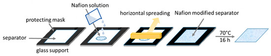
Figure 1.
Schematic procedure of separator modification.
2.2. Physicochemical Characterization of the Modified Separators
The effective deposition of a thin Nafion™ layer was confirmed by FTIR-ATR transmittance spectra of the CN01 and CN05 separators. The spectrum of CN01 in Figure 2a shows the three main characteristic peaks of Nafion™: the signal of the stretching vibration relative to the ethereal group at 982 cm−1, the symmetrical stretching signal of the sulfonate group at about 1065 cm−1, and the two peaks at 1157 and 1232 cm−1 that are related to the symmetric and asymmetric stretching of the CF2 group [24]. The very weak peak at 1630 cm−1 is related to the interaction between water and Nafion™ molecules. It is ascribed to O–H bending vibration of water molecules and, depending on the interactions of water with other molecules, it is a peculiar peak in lithiated Nafion™ [25,26]. These peaks are more intense in the CN05 spectrum (see Figure S1a), as expected. At 3496 cm−1, the extended band of OH stretching indicates the presence of water retained after the application of the Nafion™ solution. The peaks between 2839 and 2950 cm−1 and the weak peaks at 1360–1376 cm−1 and 1458 cm−1 are due to the -CH3 group vibration in C2075 membrane, asymmetric stretching and bending, respectively [27], as can be seen in the FTIR-ATR spectrum of C2075 reported in Figure S1b. The presence of these peaks in the spectrum of CN01 demonstrates that the amount of Nafion™ deposited on the separator is very low. Indeed, the spectrum of the CN05 reported in Figure S1a shows a great attenuation of these peaks, thus indicating the formation of a thicker Nafion™ layer.
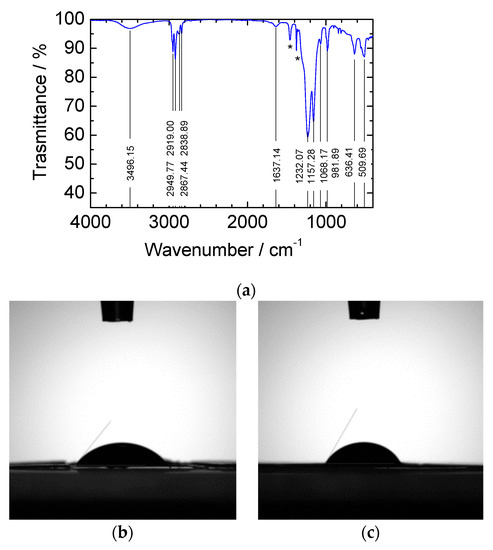
Figure 2.
(a) FTIR-ATR spectrum of CN01. The peaks indicated by an asterisk are related to the CH3 bending of C2075 (see also Figure S1). Contact angle of a drop of propylene carbonate after 10 s of the drop fall on (b) CN01 and (c) C2075.
Wettability tests were carried out on samples of pristine C2075 and CN01. Figure 2b,c shows the contact angles between the drop of propylene carbonate solvent and the separator surface 10 s after the drop fall. The measured angle is 51.5° for CN01 and 63.5° for C2075, indicating a better wettability of the former, as expected.
A preliminary evaluation of the adhesion properties of the CN01 and CN05 separators has been carried out by pressing the separator with the electrode as described in Section 3. All the samples display very good adhesion. Given that the cost of Nafion™ solution could be an issue, and that the same results have been achieved even with a very low amount of polymer coating, we decided to continue the characterization tests only on the CN01 separator. Figure 3 gives a qualitative idea of the influence of Nafion™ on the adhesion between electrodes and separators. The separators and LNMO electrodes were pressed together at 3144 kg·cm−2 for 2 min. The LNMO electrodes were previously pressed at 7860 kg·cm−2 per 1 min. While C2075 does not adhere to the electrode (Figure 3a), CN01 remains well stick to it (Figure 3b). We also carried out a comparative test with Celgard® polyolefin separator covered by PVdF (CP), kindly provided by Celgard® for this kind of test. In this case, as well, we found that separators and electrodes are very tight (Figure 3c). The SEM images of Figure 4 shows the cross-section of the pressed electrode/CN01 separator assembly: the interpenetration between the two parts is clearly evinced, thus confirming the good affinity between the LNMO and Nafion™-coated separator and indicating that the pressure applied could be lowered.
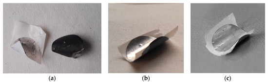
Figure 3.
Images of the separators pressed onto the LNMO electrode: C2075 (a), CN01 (b), CP (c).
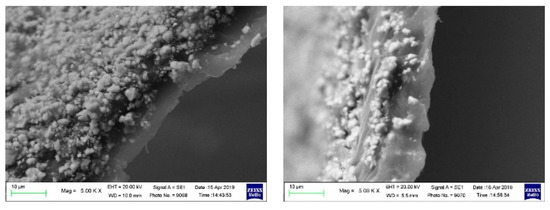
Figure 4.
SEM images of the cross-section of the pressed electrode/CN01 separator assembly.
Tensile tests were performed to evaluate the influence of Nafion™ on the strength of the separator. The specimens had a length of 4.5 cm (useful length 2.5 cm) and a width of 0.5 cm. Four tests were carried out with the load in the parallel direction to that of the fibers (MD), and four in the transverse direction (TD), for both CN01 and C2075. Figure 5a,b shows that in the parallel direction to the fibers (Figure 5a) the trend of the tension is similar, but the CN01 has lower resistance (about 140 MPa against the 190 MPa of the C2075). In the transverse direction (Figure 5b), the two specimens have similar behavior. The tensile tests reveal that both the ultimate tensile strength in the direction parallel to the fibers and the yield strength in the direction transversal to the fibers are slightly lowered by the coating. This fact certainly deserves to be further investigated, since it could be a problem in case of mechanical overloads.
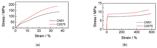
Figure 5.
Stress-strain curves of CN01 and C2075 with load (a) in the parallel direction to the fibers and (b) in the transverse direction.
Electrochemical impedance spectroscopy (EIS) measurements were carried out to evaluate the contribution of the separator to the ionic resistance of the system. Symmetric Teflon™ cells with stainless steel blocking electrodes (two-electrode configuration) were assembled with both separators, C2075 and CN01, soaked with the electrolyte (three cells for each type of separator). EIS tests were performed at 30 °C just after the assembly (t = 0) and after 1 and 4 h. Figure 6 shows the Nyquist diagrams of the separators C2075 and CN01.
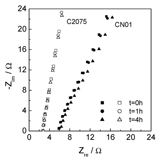
Figure 6.
Nyquist plots (range 300–20 kHz) of C2075 and CN01 soaked with LP30 at different time after assembly.
The ionic resistance of the system (Rm) has been evaluated by the fitting of the high-frequency portion of the EIS spectra and the resistivity ρeff calculated from the equation
where A is the area of the electrodes (0.785 cm2) and s is the thickness of the separator, i.e., 0.0020 cm for C2075 and 0.0026 cm for CN01. The contribution of the separator to the ionic resistance of the system is indicated by the dimensionless MacMullin number:
where ρeff is the resistivity of the separator soaked in the liquid LP30 electrolyte and ρ0 is the resistivity of the electrolyte itself, 82.5 Ωcm [28]. The resulting NM of the CN01 is 20, greater than that of the pristine (NM = 11), showing that the ionic transport is worsened by the coating. However, NM = 20 is still acceptable, and the values of NM do not change in 4 h.
ρeff = A Rm/s
NM = ρeff/ρ0
2.3. Electrochemical Characterization of the Li/LNMO Cells with Modified Separators
The performance of the modified separator was evaluated in a Li/LNMO cell by means of galvanostatic measurements compared with those of the pristine separator. Three-electrode cells were assembled in a dry box, with LNMO electrode (ca. 6–8.5 mg·cm−2) as the working electrode and the metallic lithium as the counter and reference electrode. The cells were indicated with the name of separators, CN01 and C2075. The galvanostatic charge–discharge cycles were carried out at (nominal) C/3 and 1C, i.e., ca. 0.3–0.4 and 0.9–1.2 mA·cm−2, respectively, depending on the electrode loading. Tests were also performed on cells where the separator and the electrode were pressed at 3144 kg cm−2 for 2 min to obtain an assembly like that reported in Figure 3b; the cells were labeled CN01p.
Figure 7a,b shows the discharge capacity loss over cycling at C/3 and 1C, respectively. The percentage of capacity was evaluated with respect to the third cycle for CN01 and C2075, and the 6th cycle for CN01p for the tests at C/3 rate, and with respect to the first cycle for the tests at 1C. Different initial reference cycles for the evaluation of the capacity percentage were selected as indicators of stable starting conditions for all the cells. The initial specific discharge capacity delivered by C2075, CN01 and CN01p cells at C/3 were 93, 110 and 107 mAh·g−1LNMO and at 1C were 78, 93 and 87 mAh·g−1LNMO, respectively. The initial specific capacity of the CN01 cell is higher than that of the other cells, and the capacity loss during operation is relatively low even at high currents. Indeed, despite the similar loss trend of the CN01 and C2075 cells at low current (Figure 7a), at high current, the differences are more evident (Figure 7b). While the CN01 maintains a capacity higher than 90% over more than 80 cycles, the C2075 cell displays a marked decrease in the first 20 cycles at a high rate and, hence, maintains a nearly constant capacity at ca. 85% of the initial value. On the contrary, the CN01p cell displays a very high capacity loss and reaches 80% of the initial value after 14 cycles at 1C. Although Celgard® separators are used in commercial Li-ion batteries, they do not always seem the most suitable choice for Li-ion and Li metal cells featuring high-potential LNMO cathodes. Chang et al. [29] recently demonstrated that Li//LNMO cells with a Celgard® separator show a fast capacity decay from 84 mAh g−1 to 40 mAh g−1 after 150 cycles, compared to Li//LNMO cells with a metal-organic framework-based separator that display capacity retention of 80.5% after 400 cycles. Arbizzani et al. [30] also demonstrated that graphite//LiNi0.4Mn1.6O4 cells with LiNi0.4Mn1.6O4 loading near 20 mg·cm−2 underwent a rapid decrease of capacity over 100 charge–discharge galvanostatic cycles between 3.5 V and 4.95 V, much greater than that of cells tested with PVdF-based macroporous membrane separator. On the contrary, good performance of LNMO electrodes with a water-processable binder was achieved with the Celgard® separator in coin cell configuration as described by Dong et al. [31]. However, the loading of the electrode is very low (1–1.5 mg cm−2), as well as the current densities.
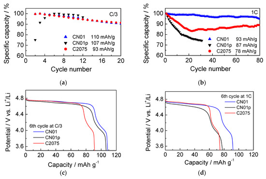
Figure 7.
Percentage of discharge specific capacity at (a) C/3 and (b) 1C; (c) discharge curves at C/3 (6th cycle) of CN01, C2075, and CN01p cells; (d) discharge curves at 1C (6th cycle) of CN01, C2075, and CN01p cells.
The reason for the capacity loss, however, does not seem related only to the different contact between the electrode and separator. Figure 7c,d shows the voltage profiles of the 6th discharge at C/3 and 1C, respectively, of the three cells CN01, CN01p, and C2075. It is evident that LNMO in CN01p displays a higher overpotential, more evident at high C-rate than the LNMO electrodes of the other cells. However, the behavior of the Li anode should be considered, too. At high current density, Li dendrites form promptly and become an additional problem, as can be seen by SEM images.
SEM measurements were carried out on the components of the CN01 and CN01p cells after the electrochemical tests. By comparing the images of pristine lithium (Figure 8a) and lithium anode after cycling in CN01 cells (Figure 8b), it is evident the massive formation of dendrites that grow because of the non-homogeneous deposition of lithium on the electrode. Dendrites create preferential paths for current flow, whose uneven distribution can cause local overheating and short circuits. If the dendrites grow excessively, they can break and form dead lithium detached from the anode or penetrate the separator and reach the cathode compartment causing short circuits. Figure 8c shows the SEM image of the CN01 separator side towards the Li electrode, and Figure 8d shows the surface of CN01p toward Li. The morphology is quite different, more porous in the former and compact in the latter. Surface analysis by EDS (Figure S2a,b) demonstrated that these layers mainly contain C, O, P and F. In the latter, also Mn is present, probably due to the mechanical pressing of CN01p assembly.
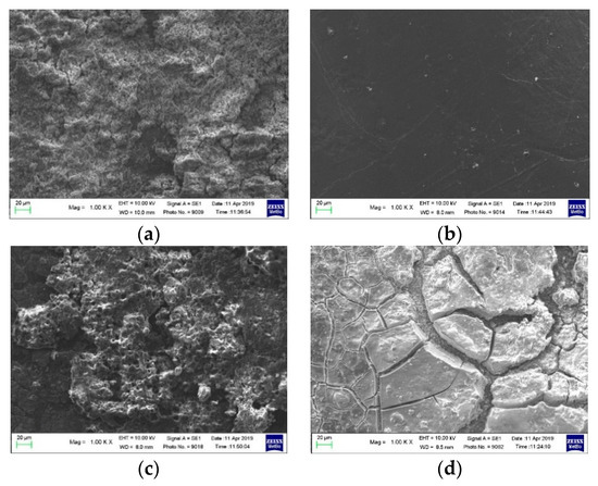
Figure 8.
SEM images of (a) pristine lithium, (b) lithium anode after cycling, separator side toward Li of (c) CN01 and (d) CN01p cells.
Figure 9 displays the SEM images of the separators (Figure 9a,c) and the corresponding LNMO electrodes (Figure 9b,d) of CN01 and CN01p cells. While the SEM images of the CN01 separator reveal only a very thin deposit on its surface (Figure 9a), which is ascribed to the outer layer of the cathode material, the separator surface of the CN01p cell exhibits a thick coating of LNMO that was partially removed from the cathode (Figure 9c). The corresponding changes on cathode surfaces are shown in Figure 9b,d.
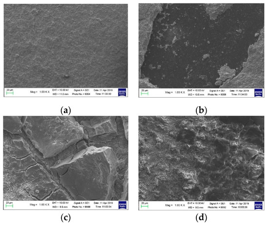
Figure 9.
SEM images of (a) surface of the separator in contact with the LNMO cathode and (b) LNMO cathode in CN01 cell; (c) surface of the separator in contact with the LNMO cathode and (d) LNMO cathode in CN01p cell.
3. Discussion
The simple methodology here presented provided modified separators with different amounts of Nafion™. The use of Nafion™ solution to modify separators could also be transferred to different methodologies, like the spray coating process, in order to obtain separators with a lower Nafion content to reduce costs. From the physicochemical characterization of the modified separator, the thickness of the layers resulted in 5 ± 1 μm for CN01 and 9 ± 1 μm for CN05. The thickest layer almost totally masks the polyolefin in FTIR-ATR spectra as is evident by the decreasing of the peaks around 2800 cm−1 and 1375–1475 cm−1 that are related to the CH3 vibrations in polypropylene. Nafion™ seems not to greatly affect the mechanical properties of the modified separators that maintain those of the pristine film, even if slightly decreased. This decrease may be due to the treatment of the separator with the alcohol-based solution of Nafion followed by heat treatment rather than to specific interactions of Nafion™ with polypropylene. Even if the Nafion™ layer was thin, it modifies the wettability of the separator surface and the adhesion properties. Despite the increased wettability due to the polarity of Nafion™ molecules, the modified separator displayed a higher MacMullin number than a pristine separator. It is likely that the film formed on the surface layer is compact and less porous than the polyolefin layer. However, the higher resistivity does not seem to affect greatly the electrochemical tests. Indeed, from the capacity data, we observed better capacity and stability for the CN01 cell. Interestingly, we also observed that the overpotentials of the LNMO electrodes in the different cells are very similar. The overpotential of the LNMO in CN01p cell is slightly higher, as expected. The comparison of the voltage profiles at the beginning and the end of the galvanostatic charge–discharge tests at 1C (Figure S3) demonstrates that LNMO overpotential increases more in CN01p than in CN01 and C2075, and over a lower cycle number. We also analyzed the voltage profile of the Li anodes (Figure S4) during the charge–discharge cycles of the cells and we found that the voltage profiles of Li oxidation in CN01 and C2075 are very similar, as expected, given that Li anode is in contact with the bare polyolefin. The voltage profile of Li in CN01p is different and the overpotential is unexpectedly lower than that of the Li anode in the previous two cells. An explanation could be that the separator surface in the separator/electrode assembly is smooth, which positively affects the contact with Li. However, if the pressure is too high, the porosity of the electrode and of the separator decreases and hinders ion transport. It is worth noting that the conditions of static pressing at 3144 kg cm−2 are not comparable to those used in the assembly of cell elements for large-scale production. Indeed, a common lamination at a speed of about 1.40 m·min−1 applies a linear force of about 160 N·cm−1 [23]. This indicates that pressing conditions should be carefully selected to avoid the interpenetration of the electrode and separator (see Figure 4), and a mild lamination should be effective with the Nafion™-modified separators.
4. Materials and Methods
The modified separators were prepared starting from a Celgard® PP2075 separator (Celgard Inc., Charlotte, NC, USA), 48% porosity, pore size 0.035 μm) and applying on one side a dispersion of lithium Nafion™ in isopropanol (LITHion™, Ion Power, d = 0.842 g/mL, η = 20 cP, concentration 10.586% (w/w)). Celgard® 2075 sheets (7 cm × 2.5 cm) were cut and blocked on a microscope slide with adhesive tape. The Nafion™ solution was diluted with absolute ethanol (99.8% purity, Sigma-Aldrich, St. Louis, MO, USA): 22 μL of solution was dissolved in 78 μL of ethanol, thus obtaining 100 μL of a solution containing 1.94 mg of Nafion™ for a Nafion™ coating of ca. 0.1 mg cm−2. A more concentrated solution was used for the samples with a coating of ca. 0.5 mg cm−2. The solution was deposited and spread on the separator. After a few minutes of air drying, the solvent evaporated. The mass of Nafion™ on the separator was estimated by weighing. The drying was completed in the Büchi B-585 oven for 16 h at 70 °C under a dynamic vacuum. The separators were then kept inside the MBraun LabMaster SP Dry Box (H2O and O2 content < 0.1 ppm).
The thickness of the separators was measured using a digital micrometer (Mitutoyo, Takatsu Ward, Kawasaki, Japan). The FTIR-ATR analysis was carried out with a Platinum-ATR (Alpha Bruker, Billerica, MA, USA). The mechanical characterization of the separator was carried out using an Instron 4465 dynamometer. The tensile tests were carried out on a useful section of 25 mm at 10 mm/min and 5 points/s. The contact angle experiments were carried out with a propylene carbonate solvent using a Theta Lite Instrument (Biolin Scientific, Västra Frölunda, Sweden) and collecting 20 images/s for 10 s.
The LNMO electrodes were prepared as described in ref. [3] using an aqueous slurry based on 87% LiNi0.5Mn1.5O4 (LNMO, NANOMYTE™ SP-10, NEI Corporation, Somerset, NJ, USA), 10% Super C65 Carbon (Imerys) and 3% sodium alginate (SA, Sigma-Aldrich, St. Louis, MO, USA). All the percentages are by weight. The ICL E-Z hydraulic press was used for pressing the LNMO electrodes at 7860 kg cm−2 for 1 min. The electrodes were then dried under dynamic vacuum in the Büchi B-585 oven at 120 °C for 16 h. The LNMO loading of the electrode (0.636 cm2) was in the range of 6–8.5 mg cm−2. The electrode/separator assembly used in CN01p cell was also obtained by pressing at 3144 kg cm−2 for 2 min. The electrolytic medium was 1M solution of lithium hexafluorophosphate LiPF6 in ethylene carbonate: dimethyl carbonate 1:1 (w/w) (LP30, Selectilyte BASF, Ludwigshafen, Germany). Teflon™ T cells (BOLA, Bolehnder, GmBH, Grünsfeld, Germany) were used for the electrochemical characterization. The cell assembly was carried out in the dry box.
The morphological characterization of the separators, electrodes, and lithium was carried out using a Zeiss EVO 50 electron scanning microscope (SEM) equipped with an energy-dispersive X-ray analyzer (EDS) from Oxford INCA Energy 350 system. The electrochemical measurements were carried out at 30 °C by a multi-channel VMP (Perkin Elmer, Waltham, MA, USA) potentiostat/galvanostat. The impedance spectra were collected at 30 °C by a Solartron SI 1255 frequency response analyzer interfaced with the PAR273A potentiostat/galvanostat, in the range 100 kHz–100 mHz, 10 points/decade, data quality 3.
5. Conclusions
Nafion™-coated separators were prepared from the Celgard® (Charlotte, NC, USA) PP2075 polyolefin separator. The physicochemical characterization of these modified separators suggests that 0.1 mg·cm−2 of Nafion™ in the form of a thin layer does not greatly affect the good mechanical properties of polyolefin. Even if the tensile strength decreases with the addition of Nafion™, the separator does not undergo large variations from a mechanical point of view. A Nafion™ layer improves the wettability of the separator but slightly increases the resistivity of the CN01 separator.
Nafion™ provides a polar feature to the separator surface, similar to that of a water-processed cathode surface. Excellent adhesion of the separator to water-processable LNMO-based cathodes featuring sodium alginate as a binder has been demonstrated by applying mechanical pressure. However, high interpenetration of separator and electrode, which can adversely affect the porosity of the two cell components, should be avoided. The good capacity and cycling stability of Li/LNMO cells with CN01 separator demonstrates that the formation of a thin Nafion™ layer could be a viable approach to modify separators for lithium and lithium-ion batteries. In addition, a mild lamination between the electrode and separator might give optimal results, providing high-performance cells with a more environmentally sustainable process. This is a good starting point for next-generation batteries that use water-processed, high-voltage cathodes.
Supplementary Materials
The following are available online at https://www.mdpi.com/2313-0105/6/2/28/s1, Figure S1: FTIR-ATR spectra of (a) CN05 Nafion-coated separator and of (b) Celgard® PP2075 separator, Figure S2: EDS spectra of the separator surface toward Li anode (see Figure 8c,d): (a) CN01 and (b) CN01p, Figure S3: First and last discharge curves at 1C of the CN01, C2075 and CN01p cells (see Figure 7c), Figure S4: Voltage profile of the Li anode oxidation process occurring during the discharge of LNMO in CN01, C2075 and CN01p cells and shown in Figure 7c,d: (a) C/3 (6th cycle), (b) 1C (6th cycle).
Author Contributions
Conceptualization, C.A., A.T., L.M.; methodology, A.T., L.M.; validation, A.T., L.M.; investigation, L.M., F.D.G., A.T.; data curation, L.M., F.D.G.; writing—original draft preparation, C.A.; writing—review and editing, C.A., F.D.G., L.M.; supervision, C.A.; project administration, C.A.; funding acquisition, C.A. All authors have read and agreed to the published version of the manuscript.
Funding
This research was funded by MSE-ENEA Electrical System Research “Energy storage for electric system” Project, PAR 2019–2021.
Acknowledgments
The Authors thank M. L. Focarete for the use of equipment for contact angle and tensile strength, F. Tarterini for SEM measurements and S. Cardillo and M. Giovagnoli (Celgard) for kindly providing separators.
Conflicts of Interest
The authors declare no conflict of interest.
References
- Goodenough, J.B.; Park, K.-S. The Li-ion rechargeable battery: A perspective. J. Am. Chem. Soc. 2013, 135, 1167–1176. [Google Scholar] [CrossRef] [PubMed]
- Placke, T.; Kloepsch, R.; Duhnen, S.; Winter, M. Lithium ion, lithium metal, and alternative rechargeable battery technologies: The odyssey for high energy density. J. Solid State Electrochem. 2017, 21, 1939–1964. [Google Scholar] [CrossRef]
- Bigoni, F.; De Giorgio, F.; Soavi, F.; Arbizzani, C. Sodium alginate: A water-processable binder in high-voltage cathode formulations. J. Electrochem. Soc. 2017, 164, A6171–A6177. [Google Scholar] [CrossRef]
- Wood, D.L.; Li, J.; Claus, D. Daniel, C. Prospects for reducing the processing cost of lithium-ion batteries. J. Power Sources 2015, 275, 234–242. [Google Scholar] [CrossRef]
- Bresser, D.; Buchholz, D.; Moretti, A.; Varzi, A.; Passerini, S. Alternative binders for sustainable electrochemical energy storage—The transition to aqueous electrode processing and bio-derived polymers. Energy Environ. Sci. 2018, 11, 3096–3127. [Google Scholar] [CrossRef]
- Jin, S.Y.; Manuel, J.; Zhao, X.; Park, W.H.; Ahn, J.-H. Surface-modified polyethylene separator via oxygen plasma treatment for lithium-ion battery. J. Ind. Eng. Chem. 2017, 45, 15–21. [Google Scholar] [CrossRef]
- Kim, J.Y.; Lee, Y.; Lim, D.Y. Plasma-modified polyethylene membrane as a separator for lithium-ion polymer battery. Electrochim. Acta 2009, 54, 3714–3719. [Google Scholar] [CrossRef]
- Lee, Y.; Ryou, M.H.; Seo, M.; Choi, J.W.; Lee, Y.M. Effect of polydopamine surface coating on polyethylene separators as a function of their porosity for high-power Li-ion batteries. Electrochim. Acta 2013, 113, 433–438. [Google Scholar] [CrossRef]
- Lee, H.; Yanilmaz, M.; Toprakci, O.; Fu, K.; Zhang, X. A review of recent developments in membrane separators for rechargeable lithium-ion batteries. Energy Environ. Sci. 2014, 7, 3857–3886. [Google Scholar] [CrossRef]
- Yu, L.; Miao, J.; Jin, Y.; Lin, J.Y.S. A comparative study on polypropylene separators coated with different inorganic materials for lithium-ion batteries. Front. Chem. Sci. Eng. 2017, 11, 346–352. [Google Scholar] [CrossRef]
- Jin, Z.; Xie, K.; Hong, X.; Hu, Z.; Liu, X. Application of lithiated Nafion ionomer film as functional separator for lithium-sulfur cells. J. Power Sources 2012, 218, 163–167. [Google Scholar] [CrossRef]
- Pan, Y.; Chou, S.; Liu, H.K.; Dou, S.X. Functional membrane separators for next-generation high-energy rechargeable batteries. Natl. Sci. Rev. 2017, 4, 917–933. [Google Scholar] [CrossRef]
- Seh, Z.W.; Sun, Y.; Zhang, Q.; Cui, Y. Designing high-energy lithium-sulfur batteries. Chem. Soc. Rev. 2016, 45, 5605–5634. [Google Scholar] [CrossRef] [PubMed]
- Dirlam, P.T.; Glass, R.S.; Char, K.; Pyun, J. The use of polymers in Li-S batteries: A review. J. Polym. Sci. 2017, 55, 1635–1668. [Google Scholar] [CrossRef]
- Terella, A.; De Giorgio, F.; Rahmanipour, M.; Malavolta, L.; Paolasini, E.; Fabiani, D.; Focarete, M.L.; Arbizzani, C. Functional separators for the batteries of the future. J. Power Sources 2020, 449, 227556. [Google Scholar] [CrossRef]
- Liang, H.-Y.; Qiu, X.-P.; Zhang, S.-C.; Zhu, W.-T.; Chen, L.-Q. Study of lithiated Nafion ionomer for lithium batteries. J. Appl. Electrochem. 2004, 34, 1211–1214. [Google Scholar] [CrossRef]
- Bae, K.Y.; Kim, M.; Kim, B.H.; Cho, S.H.; Yoon, S.S. Effect of electrostatic spray deposited Nafion coating on non-lithiated LiV3O8 cathode in lithium-metal rechargeable batteries. Solid State Ion. 2019, 331, 66–73. [Google Scholar] [CrossRef]
- Pan, Z.; Bi, Y.; An, L. A cost-effective and chemically stable electrode binder for alkaline-acid direct ethylene glycol fuel cells. Appl. Energy 2020, 258, 114060. [Google Scholar] [CrossRef]
- Yoon, W.Y.; Lee, S.H.; Kim, J.; Kim, B.-H.; Yoon, S.; Cho, K.Y. Delamination-free multifunctional separator for long-term stability of lithium-ion batteries. Small 2019, 15, 1804980. [Google Scholar]
- Gozdz, A. Electrochemical Cell Comprising Lamination of Electrode and Paper Separator Members. U.S. Patent US20030062257A1, 3 October 2001. [Google Scholar]
- Frankenberger, M.; Singh, M.; Dinter, A.; Jankowksy, S.; Schmidt, A.; Pettinger, K.-H. Laminated lithium-ion batteries with improved fast charging capability. J. Electroanal. Chem. 2019, 837, 151–158. [Google Scholar] [CrossRef]
- Meyer, C.; Bockholt, H.; Haselrieder, W.; Kwade, A. Characterization of the calendering process for compaction of electrodes for lithium-ion batteries. J. Mater. Process. Technol. 2017, 249, 172–178. [Google Scholar] [CrossRef]
- Frankenberger, M.; Madhav, S.; Dinter, A.; Pettinger, K.-H. EIS study on the electrode-separator interface lamination. Batteries 2019, 5, 71. [Google Scholar] [CrossRef]
- Kollath, V.O.; Karan, K. New molecular scale insights into the a-transition of Nafions thin films from variable temperature ATR-FTIR spectroscopy. Phys. Chem. Chem. Phys. 2016, 18, 26144–26150. [Google Scholar] [CrossRef] [PubMed]
- Sachan, S.; Ray, C.A.; Perusich, S.A. Lithium-ion transport through nonaqueous perfluoroionomeric membranes. Polym. Eng. Sci. 2002, 42, 1469–1480. [Google Scholar] [CrossRef]
- Ludvigsson, M.; Lindgren, J.; Tegenfeldt, J. FTIR study of water in cast Nafion films. Electrochim. Acta 2000, 45, 2267–2271. [Google Scholar] [CrossRef]
- Zhang, D.; Yan, K.; Wu, F.; Zhang, C. A high power density dual-electrolyte lithium-silver battery with celgard® 2325 separator. Electrochim. Acta 2014, 116, 429–433. [Google Scholar] [CrossRef]
- La Monaca, A.; De Giorgio, F.; Focarete, M.L.; Fabiani, D.; Zaccaria, M.; Arbizzani, C. Polyvinylidene difluoride-polyethylenoxide blends for electrospun separators in Li-ion batteries. J. Electrochem. Soc. 2017, 164, A6431–A6439. [Google Scholar] [CrossRef]
- Chang, Z.; Qiao, Y.; Deng, H.; Yang, H.; He, P.; Zhou, H. A stable high-voltage lithium-ion battery realized by an in-built water scavenger. Energy Environ. Sci. 2020, 13, 1197–1204. [Google Scholar] [CrossRef]
- Arbizzani, C.; De Giorgio, F.; Mastragostino, M. Characterization tests for plug-in hybrid electric vehicle application of graphite/LiNi0.4Mn1.6O4 cells with two different separators and electrolytes. J. Power Sources 2014, 266, 170–174. [Google Scholar] [CrossRef]
- Dong, T.; Zhang, H.; Ma, Y.; Zhang, J.; Du, X.; Lu, C.; Shangguan, X.; Li, J.; Zhang, M.; Yang, J.; et al. A well-designed water-soluble binder enlightening the 5 V-class LiNi0.5Mn1.5O4 cathodes. J. Mater. Chem. A 2019, 7, 24594–24601. [Google Scholar] [CrossRef]
© 2020 by the authors. Licensee MDPI, Basel, Switzerland. This article is an open access article distributed under the terms and conditions of the Creative Commons Attribution (CC BY) license (http://creativecommons.org/licenses/by/4.0/).