Article

Lithium-Ion Capacitor Safety Testing for Commercial Application

by
Omonayo Bolufawi
1,2,
Annadanesh Shellikeri
1,2 and
Jim P. Zheng
1,2,*
1
Department of Electrical and Computer Engineering, Florida A&M University-Florida State University, Tallahassee, FL 32310-6046, USA
2
Aero-Propulsion, Mechatronics and Energy Centre, Florida State University, Tallahassee, FL 32310-6046, USA
*
Author to whom correspondence should be addressed.
Batteries 2019, 5(4), 74; https://doi.org/10.3390/batteries5040074
Submission received: 3 November 2019 / Revised: 29 November 2019 / Accepted: 2 December 2019 / Published: 7 December 2019
(This article belongs to the Special Issue Batteries and Supercapacitors Aging)

Abstract

:
The lithium-ion capacitor (LIC) is a recent innovation in the area of electrochemical energy storage that hybridizes lithium-ion battery anode material and an electrochemical double layer capacitor cathode material as its electrodes. The high power compared to batteries and higher energy compared to capacitors has made it a promising energy-storage device for powering hand-held and portable electronic systems/consumer electronics, hybrid electric vehicles, and electric vehicles. The swelling and gassing of the LIC when subjected to abuse conditions is still a critical issue concerning the safe application in power electronics and commercial devices. However, it is imperative to carry out a thorough investigation that characterizes the safe operation of LICs. We investigated and studied the safety of LIC for commercial applications, by conducting a comprehensive abuse tests on LIC 200 F pouch cells with voltage range from 3.8 V to 2.2 V manufactured by General Capacitors LLC. The abuse tests include overcharge, external short circuit, crush (flat metal plate and blunt indentation), nail penetration test, and external heat test.

1. Introduction

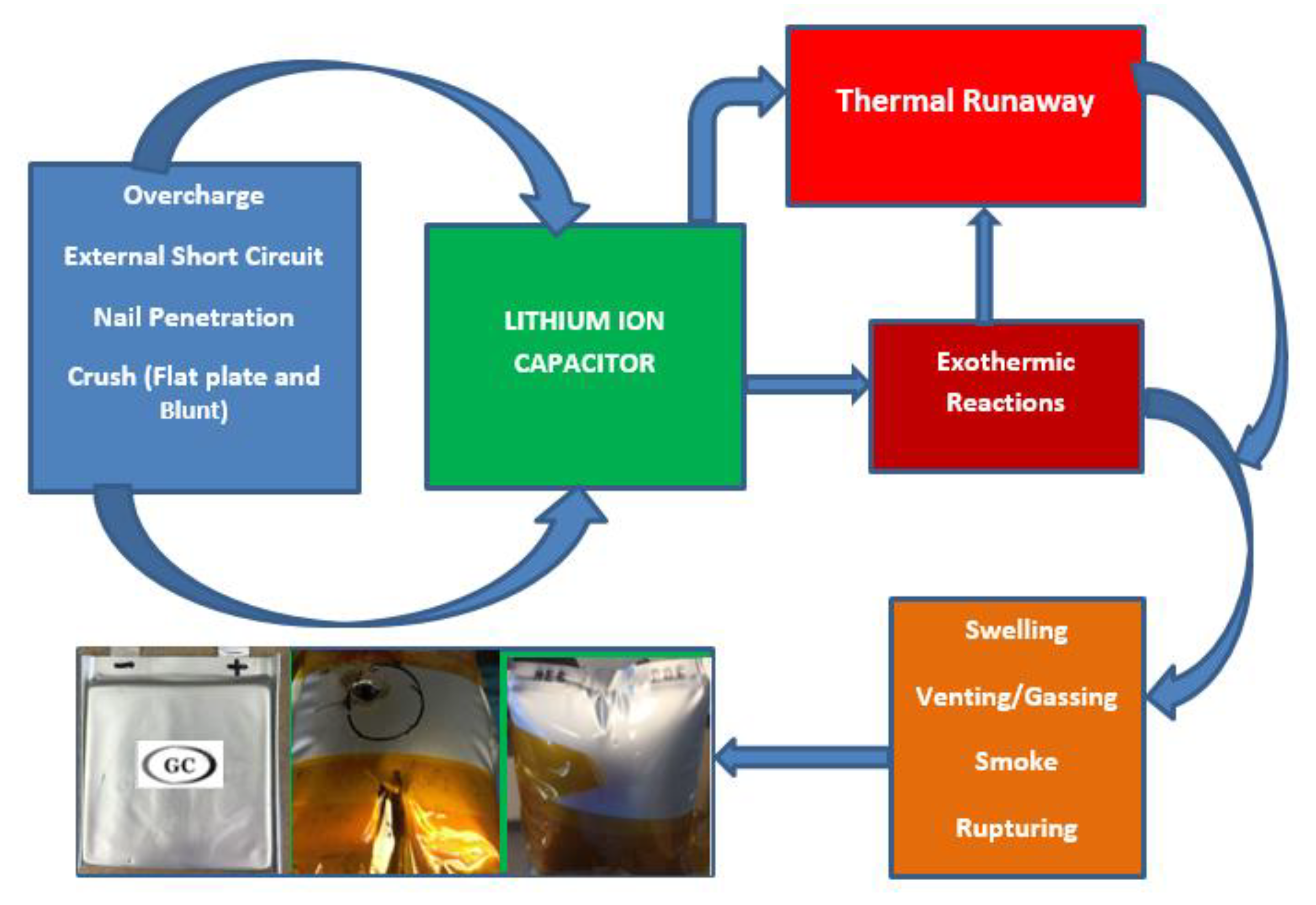
The last decade has seen increasing use of lithium-ion capacitor (LIC) in various applications due to its high power and energy density. They are also gaining traction as a power source in electric vehicles (EVs), hybrid electric vehicles (HEVs) and plug-in hybrid electric vehicles (PHEVs) because of the power and energy density and the ability of the LIC to charge and discharge fast. High demand for EVs, HEVs and PHEVs have made it imperative to investigate their safety and performance under various abuse condition. Lithium-ion capacitors are hybrid electrochemical energy-storage systems which, combine chemical reactions: Faradaic at the anode where intercalation occurs and non-Faradaic at the cathode where only surface adsorption-desorption occurs. The structure is made of lithium-ion battery anode materials (hard carbon) and electrochemical double-layer capacitor cathode (activated carbon) materials [1,2,3,4]. The electrolyte is made up of lithium LiFP6 ethylene carbonate (EC) and dimethyl carbonate (DMC) [5]. Unfortunately, one of the challenges faced by lithium-ion capacitors is the difficulty of increasing the energy and power density simultaneously with enhanced safety benefit. Recent work reported by [5] has shown that the lithium-ion capacitor can achieve both high energy and power density, and good longevity. An approach to further improve the performance of the lithium-ion capacitor has been demonstrated, [6] that uses the graphitic porous carbon (GPC) and high-purity vein graphite (PVG) prepared from Sri Lanka graphite ore by KOH activation, and high-temperature purification. An electrochemical performance with a maximum energy density of 86 Whkg−1 at 150 Wkg−1, and 48 Whkg−1 at a high-power density of 7.4 kWkg−1 was achieved at a relatively low cost. Another study [7] demonstrated a graphene-based LIC with reduced graphene oxide-carbon nanotube (rGO-CNT) film as capacitor-type electrode and pre-lithiated rGO-CNT film as battery-type electrode based on electrostatic spray deposition. Their approach delivered 114.5 Whkg−1 energy densities and maximum power density of 2569 Wkg−1. However, as the electrochemical performance of lithium-ion capacitors increases, the safety risk associated with their use increases as well [8] which generates critical concern of which parameter (performance or safety) should be compromised for the other. This concern can be address during design state for specific use case and the safety could be accounted for by using a more chemical and thermally stable materials. An embedded cell-monitoring system is a plausible way of improving the safety, but the electrochemical performance will be sacrificed due to additional weight. There is also a critical need to improve the operating temperature of the lithium-ion capacitor in order to withstand cases of abuse conditions. Temperature is one of the critical parameters that affect the stability of lithium ion capacitor [9,10,11,12] which influence the aging degradation and response to abuse conditions. However, most studies are limited to lithium-ion batteries and the safety study analysis are relatively less common for lithium ion capacitor [13,14,15,16]. Simulations and experimental studies were conducted for both external and internal short circuits of lithium ion battery, where results indicated that external short circuit is worse for smaller size batteries due to their higher internal resistance. In the internal short-circuit test, there is a higher chance of failure found due to larger battery capacity with a rise in temperature and voltage drop. The simulation model shows the capability of estimating the start time of thermal runaway. The internal temperature and structural degradation of the lithium-ion cell was investigated [17] under a nail penetration test with different penetration position for lithium ion cells, where they found out that internal temperature is higher than the surface temperature. The variation between the inner temperature and surface temperature of a supercapacitor was investigated [10] with three dimensional symmetric thermal model based on the heating rate measured during cycling [9] The modeling of increased temperature effect was studied in relation to the charge–discharge current of the supercapacitor [18] which shows that the temperature response is dependent on the current applied. The effect of thermal charging on the supercapacitor by inducing an external heat condition was reported in [19]. The mechanical integrity of lithium ion battery was investigated at cell level with a finite element model for cell compression between flat plates, where the compressive and punch indentation test are usually conducted on a stack layer because single layer with small thickness will produce less accurate result [20]. Figure 1 shows the LIC sample used for the abuse test, manufactured by General Capacitor LLC. The schematic of typical abuse conditions and responses is illustrated in Figure 2 These abuse conditions can lead to a critical failure of lithium-ion capacitors by initiating a temperature increase wherein a chain exothermic reaction leads to swelling, gassing, thermal runaway and fire [21].
Abuse tests are conducted to investigate the response of lithium-ion capacitors under conditions that exceed their normal operating mode and evaluate the thermal and chemical stability of the LIC under such conditions. The increase in temperature, as identified as major failure factor during abuse conditions is due to decomposition of the electrolyte through melting of the separator which in turn leads to exothermic reaction [22].
The previous study [23], investigated the performance of the same LIC manufactured by General Capacitor at wide temperature range electrolytes. We expanded further to study the safety performance of LIC pouch cells by investigating and monitoring their abuse response in terms of voltage, current, and temperature during the abuse testing.

2. Experimental Method

Lithium-ion capacitor pouch cells manufactured by General Capacitors were tested. The LIC cells were prepared using commercialized active materials for positive and negative electrodes. The positive and negative electrode consisted of activated carbon and graphite/hard carbon respectively. The cell specification is provided in Table 1.
Abuse tests conducted include the following; external short circuit, overcharge, external heating, nail penetration, flat metal plate, and blunt indentation crush tests. The abuse tests were conducted in a transparent glass door safety box for personal protection and observation of physical real-time reaction. An Omega type K thermocouple (accuracy 1 °C) were attached to the cell’s surface to data log the surface temperature. Likewise, the Arbin BT2000 test station was used to apply charge and discharge operation where necessary and to record the voltage and current during the abuse test. An external short circuit occurs as result of cell cathode and anode terminals being connected via a conducting path [24] which causes a high flow of current with rapid conversion of stored chemical energy to heat. The external short-circuit test was initiated using a low-resistance (<0.1 ohms) connecting wire. Overcharge is an electrical abuse condition that occurs when current is forced into the cell beyond its normal operating voltage limit [25] and the equation for energy balance during the overcharge condition is expressed in Equation (1):
Q o v e r c h a r g e =   i o c 2   L i σ i
where i o c 2   is the overcharging current, L i is the thickness of the cell materials, σ i   is the cell material conductivity.
Some of the reasons for overcharge includes power surge, faulty charger and battery management etc. [26,27,28]. Overcharge can be a severe abuse test since additional energy is added to the cell leading to chemical and thermal instability [29,30]. In the overcharge test, the LIC was charged at three times higher current beyond the voltage limit specified by the manufacturer. The nail penetration test is an important mechanical abuse test that illustrates the piercing of a LIC during a crash. A real-life occurrence was in the case of Tesla Model S battery pack that caught fire after a metallic object impact on the road [31]. Nail penetration induces an internal short circuit that can lead to thermal runaway after an exothermic reaction caused by heating [27,32]. Heat is generated by both the nail and the cell due to large current flowing through them such as ohmic heating [22,25] The LIC nail penetration test was conducted by a stainless-steel nail with full penetration at full state of charge. The position of the penetration was perpendicular to the electrode’s surfaces of the LIC. The nail diameter was 0.3 cm, 7.8 cm in length. The nail joint was attached to a hydraulic press to drive the nail through the cell while ensuring the cell was correctly positioned in a holder to avoid movement during the penetration. The impact/crush test determines the ability of the LIC to withstand an impact or crush (flat metal plate and blunt indentation). The stress-strain compression relationship during a mechanical crush test is expressed in Equations (2) and (3) to describe the material behavior by the yield surface (Y) based on finite element modeling for detecting onset short circuit due to mechanical loads and deformation [33]:
Y =   Y c + ε v   ,   δ i   > 0
Y =   Y t ,   δ i < 0
where Y c is the compression stress cut of stress, ε v is the volumetric strain, δ i is the principal stress,   Y t is the tensile cut-off stress.
The LIC at full state of charge was crushed between two flat plates and indented by round metal of 2.47 cm diameter until the cell voltage drops to zero volts, or the cell is deformed. As the cell is indented, the indenter compresses the cathode, separator, and anode. External heat was applied on LIC to observe their thermal stability which could also be referred to as a thermal ramp test by placing in a thermostatically controlled oven (FO-19000 Series Forced Air Drying Oven). The oven microcontroller was used to regulate the internal temperature of the oven with an internal fan being used to circulate the oven air to ensure temperature uniformity around the cell. The LIC was placed inside the oven on an insulated surface to avoid conduction. The oven temperature was set to 300 °C until plausible thermal runaway occurrence.

3. Electrochemical–Thermal Reaction Mechanisms Governing Equation

The electrochemical–thermal reaction mechanism of lithium-ion cells are governed by the electrochemical and thermal equations expressed in Equations (3)–(6) due to exothermic reactions. Exothermic chemical reactions are related to thermal abuse mechanisms which occur inside a cell as the temperature rises. This may generate heat that accumulates inside the cell and accelerates the chemical reaction between the cell components, if the heat-generation rate exceeds the dissipation rate to the surroundings. External conditions for a temperature rise can be external heating, over-charging or over-discharging, nail penetration, and external short etc. In these cases, a thermal runaway can occur as a consequence with leakage, smoke, gas venting, flames etc., which leads to the destruction of the cells [34,35].
The current flow through the nail during the penetration can be determined from the ratio of the voltage drop and the nail resistance based on Ohm’s law. The resistance of the nail can be estimated using Equation (4):
R =   σ l A
where σ is the electrical conductivity of the material, l; is the length and A; is the cross-sectional area of the nail.
The nail properties and the contact resistance affect the response of the cell and the internal shorting resistance created by the nail is expresses as:
R s = R n a i   l   +   R c t
R s is the internal shorting resistance, R n a i   l is the nail resistance and R c t is the contact resistance
The electrical resistivity is the inverse of electrical conductivity. Therefore, according the Matthiessen’s rule, [36] the temperature dependence of metal resistivity is expressed as shown in Equations (6) and (7):
1 σ =   1 σ o [ 1 + β ( T T o ) ]
R = R o [ 1 + β ( T T o ) ]
where T is the metal temperature, β is the temperature coefficient of resistivity. σo and To are the electrical conductivity and the reference temperature.
The heat generation inside a lithium-ion cell is produced majorly from electrochemical operation, joule heating, entropy change and heat transferred to ambient conditions by convection [37,38,39,40,41,42]. The heat can be estimated based on the thermodynamic energy balance generally expressed in Equation (8):
m L I C C p d T L I C d t =   I 2 R +   T L I C Δ S   1 n F + A h ( T L I C   T a m b )
where the first term is heat generation due to joule heating and the second term is the heat generation due to entropy changes and the third term is the heat transferred to ambient conditions by convection. The parameters in Equation (8) above are defined as: m L I C is the LIC mass, C p is the specific heat capacity, I is the current, R is the cell internal Resistance, T L I C is the LIC temperature, ΔS is the entropy change, A is the surface area, h is the heat transfer coefficient, T a m b is the ambient temperature.

4. Result and Discussion

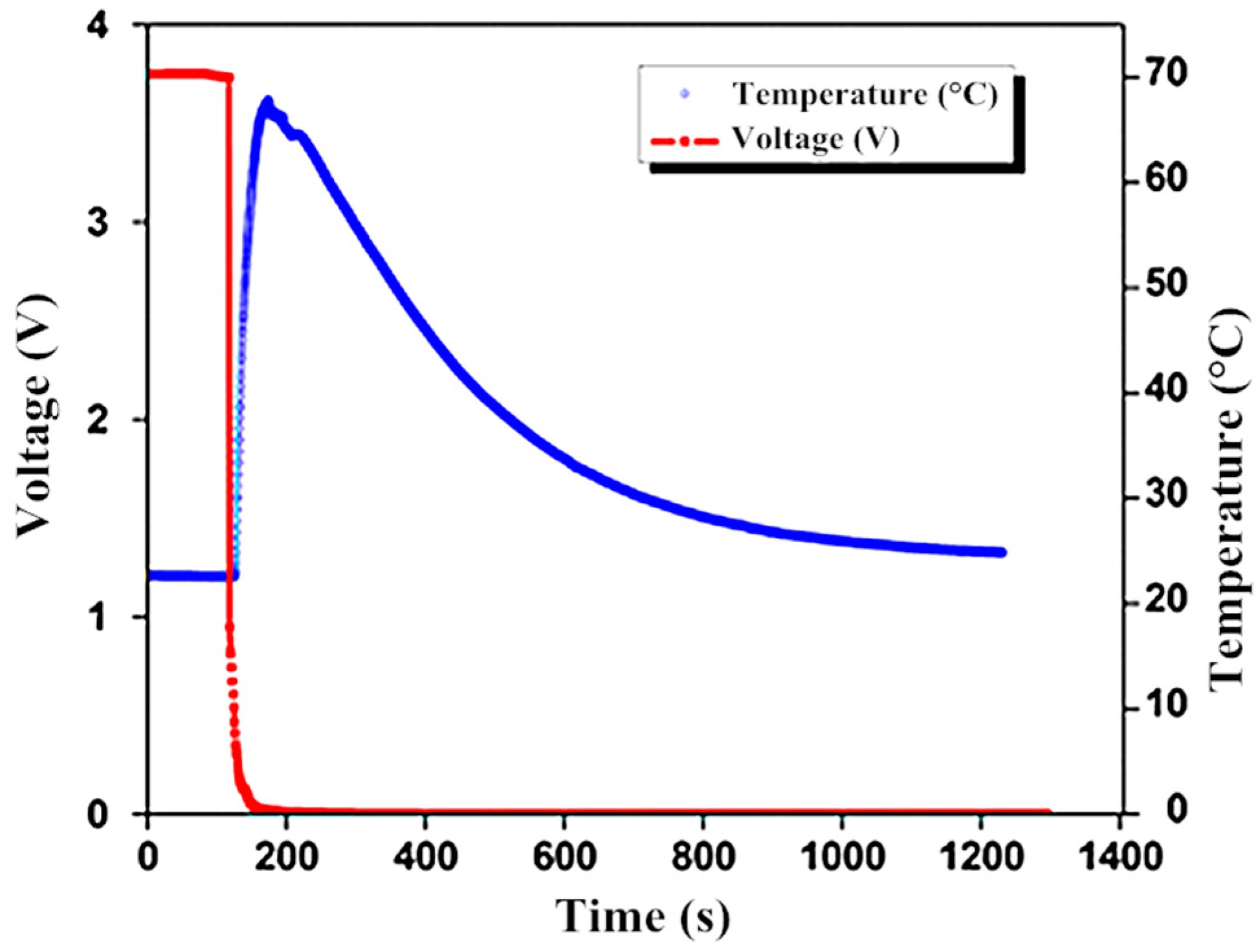
Figure 3 shows the temperature, voltage vs. time plot during the LIC external short-circuit test which indicates a sudden drop in the cell voltage because of excess current with a rise in temperature which leads to pressure on the ion flow and venting. The cell swells with an increase in temperature as well as an increase in the cell thickness due to internal rupturing and gassing. The possible solution for the cell gassing is to use electrolyte additives to enhance stability as studied [23]. A maximum surface temperature of 68 °C was reached due to the exothermic reaction caused by internal heat generation but does not result in thermal runaway.
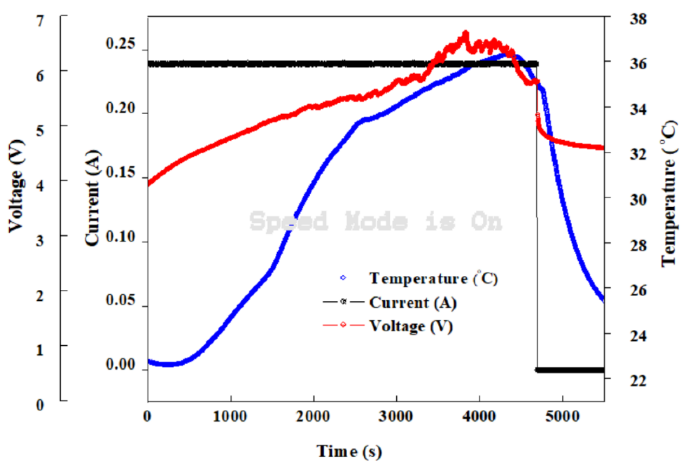
The overcharge abused response occurred at a condition beyond the normal charge state. The voltage, current and temperature were observed and plotted to describe their relationship during the overcharge condition. The LIC started overcharging when the rate of lithium insertion from cathode to anode increases due to increasing potential leading to lithium plating. Figure 4 shows the overcharged test result with a cell surface temperature plateau at 37 °C and a minimal weight loss observed because of minor venting of the electrolyte. The overcharge test led to swelling, gassing and temperature rise due to the exothermic reaction between the electrodes and electrolyte decomposition [43].
During cell overcharging, the lithium ions remaining in the cathode are removed and more lithium ions are intercalated in the anode. However, if the lithium insertion ability of the anode is small, lithium metal may be deposited on the anode [44]. The cell response, in this case, is not extremely catastrophic (resulting in only swelling of the cell due to internal gas formation) because of the lower charging current but a more catastrophic response (fire or explosion) could occur when overcharged at a higher current rate [18]. The heat generated by the applied current does not vary its behavior like the cell surface temperature but increases proportionally with current rates. Joule heating gives the relationship for the heat generated by the cell described in Equation (9).
Q = I 2 R
where Q is the Joule heating in J/s, I is the current, R is the cell internal resistance.
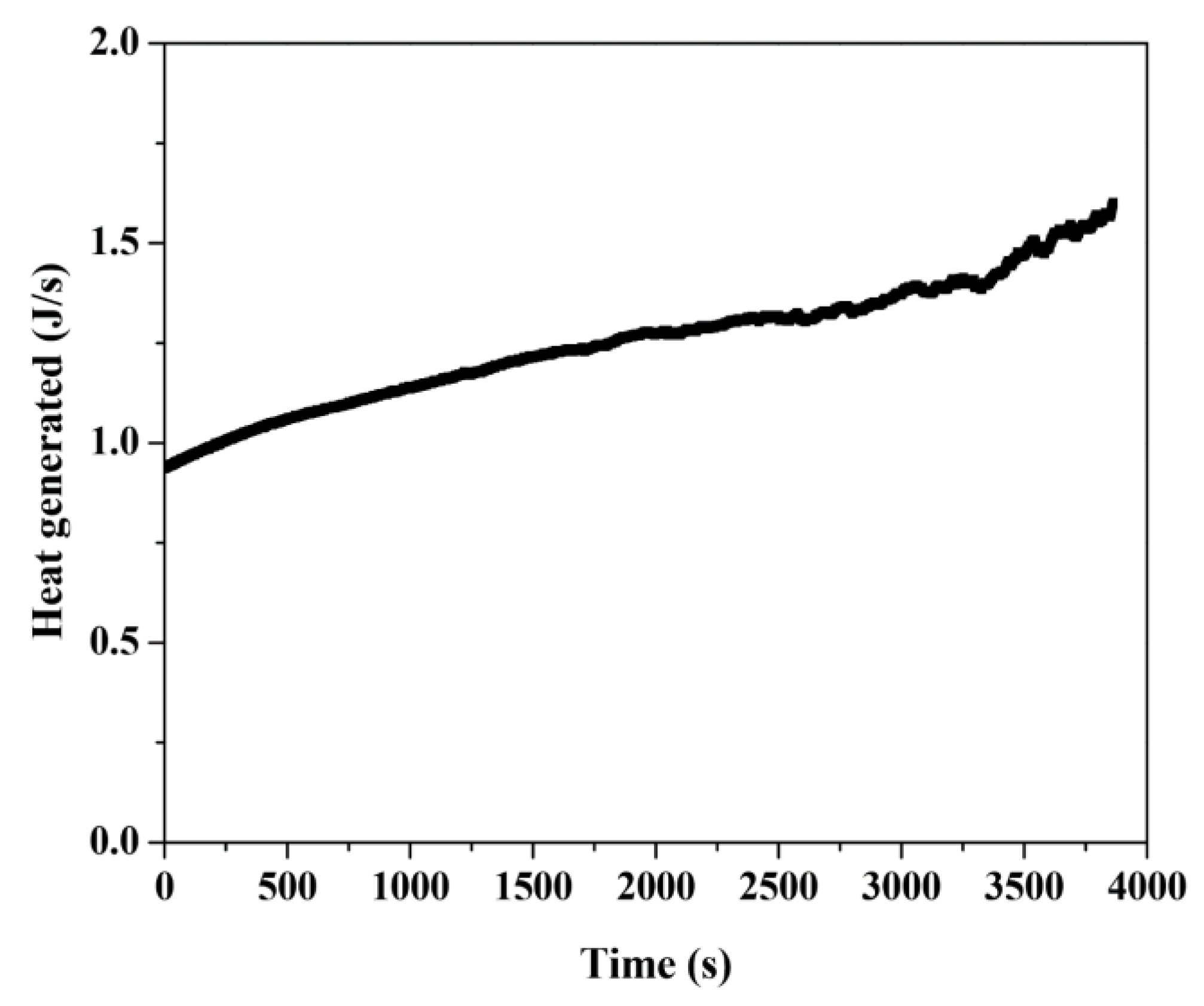
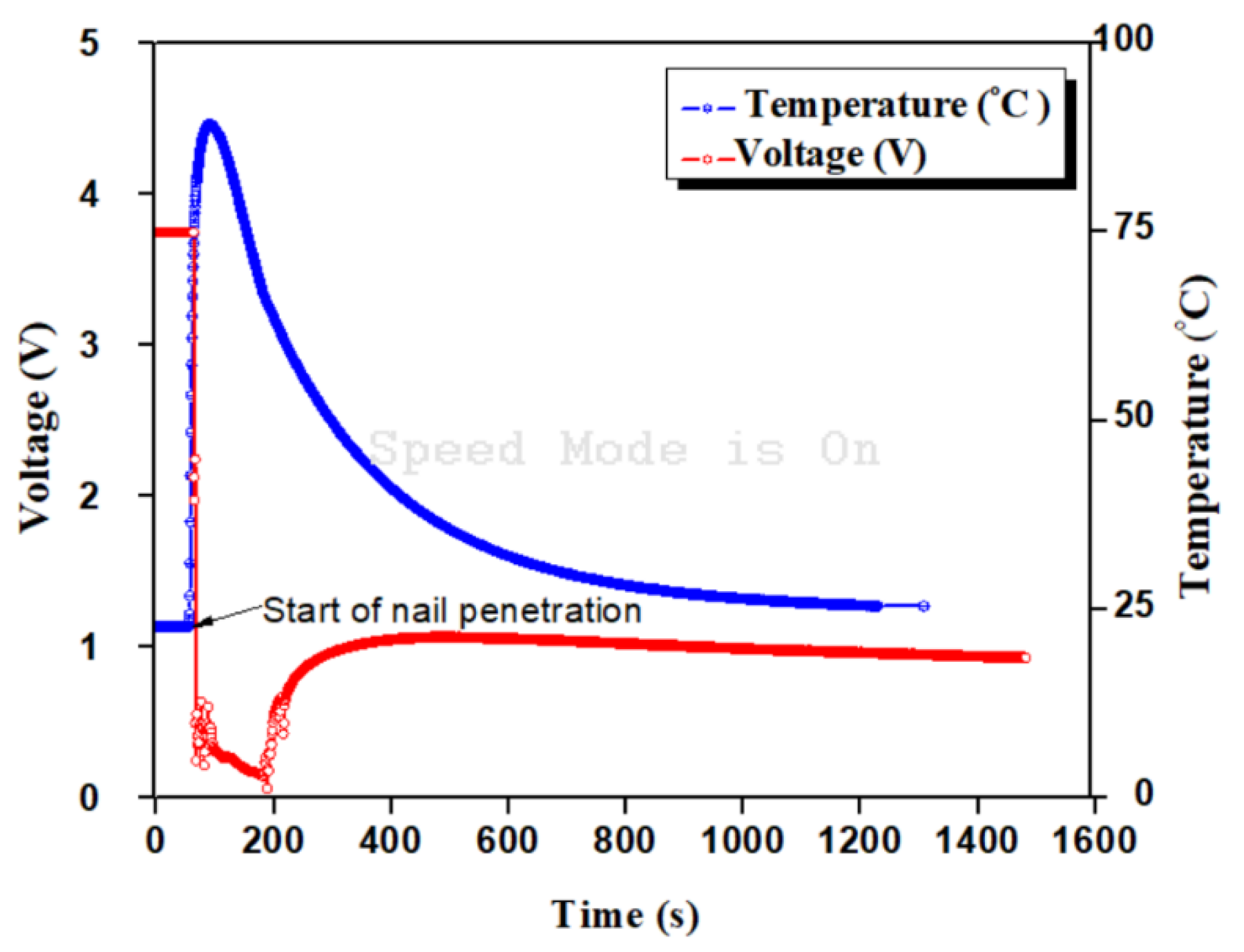
The overcharging current applied to the LIC is mainly responsible for the initial heat generation and not necessarily chemical reactions until the cell reaches a critical point beyond the cell range of operation. [43]. Figure 5 shows a heat generated over time estimated on experimental data and Equation (9) with constant current and varying overcharge voltage during the overcharge process with 1.6 J/s heat generated. The internal resistance was computed with Ohm’s law by taking the ratio of the continuous overcharging voltage to the constant current thereby giving a varying resistance value. The profile indicated the amount of heat the cell generated due to rupturing and internal reaction; this reaction is believed to be a result of the decomposition of electrodes and electrolyte which affect the thermal stability of the lithiated electrode. Figure 6 shows the result of LIC nail penetration test with a sudden drop in the LIC voltage and a corresponding rapid increase in the cell surface temperature. The instantaneous voltage-drop during internal short circuit is due to loss of potential difference when the anode and cathode at different potentials are connected due to conductive stainless-steel nail material, resulting in large current flow. The start of nail penetration as illustrated in Figure 6, shows the trigger point for the instantaneous voltage drop (large current flow) followed by rise in temperature, which initiates the decomposition of the electrolyte [43], which are exothermic reactions. This generates more heat, which in turn triggers a thermal runaway, generating gaseous products.
Upon nail removal, the cell temperature decreases, and the cell does not explode violently because the nail made a partial opening for the release of gaseous products. The cell temperature peaked at 90 °C with excessive gassing, smoke, and swelling. Figure 7 and Figure 8 show the result for blunt indentation and flat metal plate crush test respectively. As the LIC was indented, due to mechanical impact, the indenter compresses the cathode, separator, and the anode thereby creating an internal short that led to a temperature rise to about 120 °C within a few seconds when crushed.
Indenting the cell with a round metal piece created a more focused compression on the center of the cell making it like a nail penetration but with a wider contact surface area. The onset temperature for thermal runaway varied inversely with the degree of lithiation of the negative electrode [45] in which the thermal stability of the cell was reported to increase with increasing lithiation of the cathode.
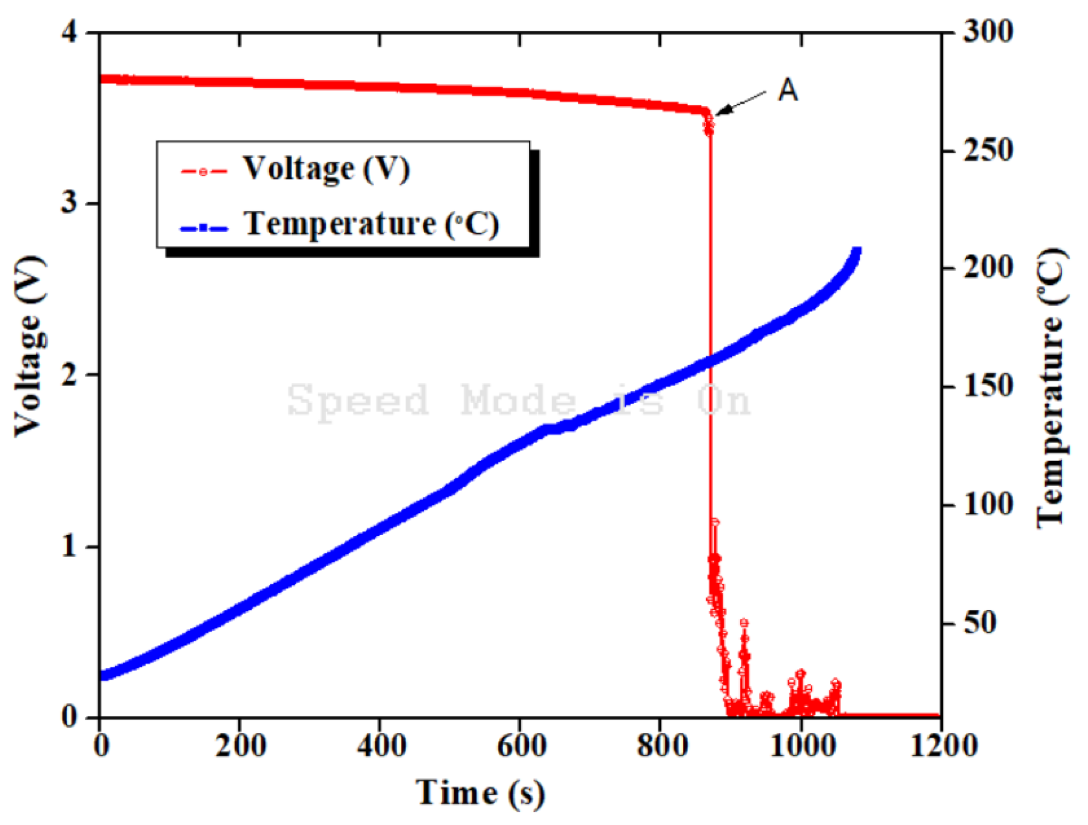
The abuse tolerance of lithium-ion cells depends on the rate of generation and dissipation of heat from the cell. When a cell cannot transfer heat to its environment at a rate equal or higher than the rate of heat generation, the cell is subject to thermal runaway. Similarly, in the flat-plate crush test, a sudden increase in temperature was observed which was believed to be due to internal heat generation resulting from internal short-circuit of anode and cathode electrodes. There is the possibility of thermal diffusion between the flat metal plate and the cell in which the flat metal plate absorbs certain percent of the heat generated. However, the amount of heat absorbed by the flat metal plate was not accounted for in this study. Figure 9 shows the voltage and temperature with respect to time during the external heating test. A rapid surface temperature was observed with the cell gassing, venting and smoke but no fire. External heating of the LIC is at higher risk of fire since additional heat was applied to investigate its thermal stability tolerance. However, the cell did not result in a catastrophic fire but vented and smoked excessively. The maximum cell surface temperature reached 210 °C due to the exothermic reaction which is attributed to the decomposition of electrolyte and electrode thus resulting in thermal runaway. During the continuous heating, it took about 15 min for the cell surface temperature to reach 163 °C which was the point where the cell voltage terminals were disconnected due to physical damage as indicated at point A on Figure 9. The cell voltage drops to 0 V, as shown in Figure 9, resulted from the voltage terminal disconnection during the gas venting, which compromised the cell integrity. The gaseous products were a result of electrolyte decomposition, which was triggered by the rising cell temperature [46,47].
The lithium-ion capacitor demonstrated a relatively safe, improved thermal and chemical stability because of their electrode materials composition which has minimal oxide content that could serve as catalyst for heat generation. The LIC is relatively safer than lithium-ion batteries when compared to a previous study [9] on lithium-ion batteries. From studies, the heat generation was reported to be due to reasons such as: the irreversible resistive heating, the reversible entropic heat, the heat change of chemical side reactions, and heat of mixing due to the generation and relaxation of concentration gradients [48]. Irreversible resistive heat loss occurred when current flows through internal resistance during charge and discharge which cause deviation of the cell potential from its equilibrium and the cell voltage difference is converted to heat. The heat by entropy change is relatively small compared to heat from resistive heating. The internal temperature of the LIC may be higher than the measured surface temperature because the heating begins inside the cell due to exothermic reaction before conducting outwards through the electrode layers towards the outer surface [17,49]. However, the present study accounts for the external surface temperature only. The nail penetration test demonstrated an instant internal shorting of the LIC cathode and anode electrodes, thus generating heat due to the exothermic reaction from decomposition of the electrode and electrolyte leading to a temperature increase. The temperature increased rapidly to about 90 °C in about 40 s before gradually decreasing because of the separator damage [47]. The temperature continued to decline until the cell was fully discharged with total energy dissipation. Due to the high specific surface area of the electrode, the heat generated was believed to have sufficiently distributed over the electrode surface which helps to reduce the temperature rise during abuse conditions. The LIC swelled, vented, gassed and smoked but there was no fire during overcharge as showed in Figure 10a.
These abuse responses portray LICs to have a promising safe operation in power electronics and commercial electronic device applications. As the cathode is completely de-lithiated during overcharge, the cell voltage overcharged above 6.5 V, the ionic conduction ceased, and the flow of current through the cell became ohmic resulting in joule heating. An overcharge abuse test can be very severe since additional energy is added to the cell. In the nail penetration result shown in Figure 6, a constant voltage and temperature were observed at the start of the experiment. However, the voltage dropped to zero and the surface temperature of the cells rose to about 100 °C, which is related to a high rate of current resulting in joule heating. The peak temperature shows that the intensity of the current during the nail penetration is believed to be high. The mechanism of nail penetration can be compared with the outgrown of dendrite in the cell that initiates internal shorting. The penetrated cell does not explode violently as the nail penetration made way for the release of gaseous products which reduce the internal pressure of the cell. In nail penetration, the nail makes direct contact between the anode and cathode as illustrated in Figure 10b. Contrary to the crush test, the flat metal plate was used to horizontally compress the cell which initiated internal short-circuiting of the electrodes, thereby giving room for the flow of current in the cell similar to the nail penetration with maximum surface temperature of 135 °C. During LIC external heating, the open-circuit voltage remained stable until about 150 °C measured on the cell surface as seen in Figure 9, then fell rapidly leading to excessive smoke and explosion as shown in Figure 10c,d. This effect was due to separator breakdown since the melting points of typical separator materials polyethylene and polypropylene are at about 130 °C [47]. The final voltage drops occurred at about 175 °C because of a delay in heat dissipation which occur when the cells generate heat more than it can dissipate. The state of charge is believed to influence cell behavior when abused and may vary according to the type of abuse conditions. The total energy release and emitted gas could not be accounted for during the explosion which also constitutes a fraction of the energy release.

5. Conclusions

The safety of lithium ion capacitor was investigated under different abuse tests with varying response observed for each test case. The high specific surface area of LIC electrode is believed to enhance the thermal and chemical stability with reduced thermal runaway and fire effect. Therefore, a lithium-ion capacitor provides safety benefits because it is less flammable making it a promising electrochemical energy storage device for safe applications in portable and consumer electronics.

Author Contributions

Experimental design, execution and original draft preparation, O.B.; Review, result and discussion, all authors.

Funding

This research was funded by NATIONAL SCIENCE FOUNDATION, grant number 0812121.

Conflicts of Interest

The authors declare no conflict of interest.

References

  1. Cao, W.J.; Zheng, J.P. The effect of cathode and anode potentials on the cycling performance of Li-Ion capacitors. J. Electrochem. Soc. 2013, 160, A1572–A1576. [Google Scholar] [CrossRef]
  2. Zheng, J.P. The limitations of energy density of battery/double-layer capacitor asymmetric cells. J. Electrochem. Soc. 2003, 150, A484–A492. [Google Scholar] [CrossRef]
  3. Zheng, J.P. Theoretical energy density for electrochemical capacitors with intercalation electrodes. J. Electrochem. Soc. 2005, 152, A1864–A1869. [Google Scholar] [CrossRef]
  4. Zheng, J.P. High energy density electrochemical capacitors without consumption of electrolyte. J. Electrochem. Soc. 2009, 156, A500–A505. [Google Scholar] [CrossRef]
  5. Cao, W.J.; Zheng, J.P. Li-ion capacitors with carbon cathode and hard carbon/stabilized lithium metal powder anode electrodes. J. Power Sour. 2012, 213, 180–185. [Google Scholar] [CrossRef]
  6. Gao, X.; Zhan, C.; Yu, X.; Liang, Q.; Lv, R.; Gai, G.; Shen, W.; Kang, F.; Huang, Z.H. A high performance lithium-ion capacitor with both electrodes prepared from Sri Lanka graphite ore. Materials 2017, 10, 414. [Google Scholar] [CrossRef]
  7. Adelowo, E.; Baboukani, A.; Chen, C.; Wang, C. Electrostatically sprayed reduced graphene oxide-carbon nanotubes electrodes for lithium-ion capacitors. J. Carbon Res. 2018, 4, 31. [Google Scholar] [CrossRef] [Green Version]
  8. Belov, D.; Yang, M.H. Failure mechanism of Li-ion battery at overcharge conditions. J. Sol. State Electrochem. 2008, 12, 885–894. [Google Scholar] [CrossRef]
  9. Lee, D.H.; Kim, U.S.; Sim, C.B. Modelling of the thermal behaviour of an ultracapacior for a 42-V automotive electrical system. J. Power Sour. 2008, 175, 664–668. [Google Scholar] [CrossRef]
  10. Gualous, H.; Louahlia-Gualous, H.; Gallay, R.; Miraoui, A. Supercapacitor thermal modelling and characterization in transient state for industrial applications. IEEE Trans. Ind. Appl. 2009, 45, 1035–1044. [Google Scholar] [CrossRef]
  11. Monzer Al, S.; Gualous, H.; Van Mierlo, J.; Culcu, H. Thermal modeling and heat management of supercapacitor modules for vehicle applications. J. Power Sour. 2009, 194, 581–587. [Google Scholar]
  12. Zubieta, L.; Bonert, R. Characterization of double-layer capacitors for power electronics applications. IEEE Trans. Ind. Appl. 2000, 36, 199–205. [Google Scholar] [CrossRef]
  13. Hu, H.; Zhao, Z.B.; Zhang, R.; Bin, Y.Z.; Qiu, J.S. Polymer casting of ultralight graphene aerogels for the production of conductive nanocomposites with low filling Content. J. Mater. Chem. A 2014, 2, 3756–3760. [Google Scholar] [CrossRef]
  14. Song, Z.; Sun, K. Adaptive backstepping sliding mode control with fuzzy monitoring strategy for a kind of mechanical system. ISA Trans. 2014, 53, 125–133. [Google Scholar] [CrossRef]
  15. Guo, G.; Bo, L. Three-dimensional thermal finite element modeling of lithium-ion battery in thermal abuse application. J. Power Sour. 2010, 195, 2393–2398. [Google Scholar] [CrossRef]
  16. Wang, K.; Li, L.; Zhang, T.; Liu, Z. Nitrogen-doped graphene for supercapacitor with long-term electrochemical stability. Energy 2014, 70, 612–617. [Google Scholar] [CrossRef]
  17. Finegan, D.P.; Tjaden, B.; Heenan, T.M.; Jervis, R.; Di Michiel, M.; Rack, A.; Hinds, G.; Brett, D.J.; Shearing, P.R. Tracking internal temperature and structural dynamics during nail penetration of lithium-ion cells. J. Electrochem. Soc. 2017, 164, A3285–A3291. [Google Scholar] [CrossRef]
  18. Wang, K.; Li, L.; Yin, H.; Zhang, T.; Wan, W. Thermal modelling analysis of spiral wound supercapacitor under constant-current cycling. PLoS ONE 2015, 10, e0138672. [Google Scholar] [CrossRef] [Green Version]
  19. Al-zubaidi, A.; Ji, X.; Yu, J. Thermal charging of supercapacitors: A perspective. Sustain. Energy Fuels 2017, 1, 1457–1474. [Google Scholar] [CrossRef]
  20. Kermani, G.; Sahraei, E. Characterization and modeling of the mechanical properties of lithium-ion batteries. Energies 2017, 10, 1730. [Google Scholar] [CrossRef] [Green Version]
  21. Larsson, F.; Mellander, B. Abuse by external heating, overcharge and short circuiting of commercial lithium-ion battery cells. J. Electrochem. Soc. 2014, 161, A1611–A1617. [Google Scholar] [CrossRef]
  22. Lee, C.W.; Venkatachalapathy, R.; Prakash, J. A Novel Flame-Retardant Additive for Lithium Batteries. Electrochem. Sol. State Lett. 2000, 3, 63–65. [Google Scholar] [CrossRef]
  23. Cappetto, A.; Cao, W.J.; Luo, J.F.; Hagen, M.; Adams, D.; Shelikeri, A.; Xu, K.; Zheng, J.P. Performance of wide temperature range electrolytes for Li-Ion capacitor pouch cells. J. Power Sour. 2017, 359, 205–214. [Google Scholar] [CrossRef]
  24. Arora, A.; Medora, N.K.; Livernois, T.; Swart, J. Safety of Lithium-Ion Batteries for Hybrid Electric Vehicles. In Electric and Hybrid Vehicle; Elsevier: Amsterdam, The Netherlands, 2010. [Google Scholar]
  25. Spotnitz, R.; Franklin, J. Abuse Behavior of High-Power, Lithium-Ion Cells. J. Power Sour. 2003, 113, 81–100. [Google Scholar] [CrossRef]
  26. Tobishima, S.; Yamaki, J. A consideration of Lithium Cell Safety. J. Power Sour. 1999, 81–82, 882–886. [Google Scholar] [CrossRef]
  27. Biensan, P.; Simon, B.; Peres, J.P. On Safety of Lithium-Ion Cells. J. Power Sour. 1999, 81–82, 906–912. [Google Scholar] [CrossRef]
  28. Saito, Y.; Takano, K.; Negishi, A. Thermal behaviors of lithium-ion cells during overcharge. J. Power Sour. 2001, 97–98, 693–696. [Google Scholar] [CrossRef]
  29. Leising, R.A.; Palazzo, M.J.; Takeuchi, E.S.; Takeuchi, K.J. Abuse Testing of Lithium-Ion Batteries: Characterization of the Overcharge Reaction of LiCoO2/Graphite Cells. J. Electrochem. Soc. 2001, 148, A838. [Google Scholar] [CrossRef]
  30. Leising, R.A.; Palazzo, M.J.; Takeuchi, E.S.; Takeuchi, K.J. A study of the overcharge reaction of lithium-ion batteries. J. Power Sour. 2001, 97–98, 681–683. [Google Scholar] [CrossRef]
  31. Abada, S.; Marlair, G.; Lecocq, A.; Petit, M.; Sauvant-Moynot, V.; Huet, F. Safety Focused Modeling of Lithium-Ion Batteries: A Review. J. Power Sour. 2016, 306, 178–192. [Google Scholar] [CrossRef]
  32. Sahraei, E.; Meier, J.; Wierzbicki, T. Characterizing and modeling mechanical properties and onset of short circuit for three types of lithium-ion pouch cells. J. Power Sour. 2014, 247, 503–516. [Google Scholar] [CrossRef]
  33. Zavalis, T.G.; Behm, M.; Lindbergh, G. Investigation of Short-Circuit Scenarios in a Lithium-Ion Battery Cell. J. Electrochem. Soc. 2012, 159, A848. [Google Scholar] [CrossRef]
  34. Ouyang, D.; Chen, M.; Huang, Q.; Weng, J.; Wang, Z.; Wang, J. A review on the thermal hazards of the lithium-ion battery and the corresponding countermeasures. Appl. Sci. 2019, 9, 2483. [Google Scholar] [CrossRef] [Green Version]
  35. Yamauchi, T.; Mizushima, K.; Satoh, Y.; Yamada, S. Development of a simulator for both property and safety of a lithium secondary battery. J. Power Sour. 2004, 136, 99–107. [Google Scholar] [CrossRef]
  36. Melcher, A.; Ziebert, C.; Lei, B.; Zhao, W.; Luo, J.; Rohde, M.; Seifert, H.J. Modeling and Simulation of Thermal Runaway in Cylindrical 18650 Lithium-Ion Batteries. In Meeting Abstracts the Electrochemical Society; The Electrochemical Society: Pennington, NJ, USA, 2016; p. 425. [Google Scholar]
  37. Matula, R.A. Electrical resistivity of copper, gold, palladium and silver. J. Phys. Chem. 1979, 8, 1147. [Google Scholar] [CrossRef] [Green Version]
  38. Benger, R.; Wenzl, H.; Beck, H.; Jiang, M.; Ohms, D.; Schaedlich, G. 2009 Electrochemical thermal modeling of lithium-ion cells for use in HEV or EV application. World Electr. Veh. J. 2009, 3, 342. [Google Scholar] [CrossRef] [Green Version]
  39. Jeon, D.H.; Baek, S.M. Thermal modeling of cylindrical lithium ion battery during discharge cycle. Energy Convers. Manag. 2011, 52, 2973–2981. [Google Scholar] [CrossRef]
  40. Wang, F.; Li, M. Thermal performance analysis of the Lithium-ion Batteries. In Proceedings of the 2010 International Conference on Parallel and Distributed Computing, Applications and Technologies (PDCAT), Wuhan, China, 8–11 December 2010; pp. 483–486. [Google Scholar]
  41. Soltani, M.; Ronsmans, J.; Kakihara, S.; Jaguemont, J.; Van den Bossche, P.; van Mierlo, J.; Omar, N. Hybrid battery/lithium-ion capacitor energy storage system for a pure electric bus for an urban transportation application. Appl. Sci. 2018, 8, 1176. [Google Scholar] [CrossRef] [Green Version]
  42. Onda, K.; Ohshima, T.; Nakayama, M.; Fukuda, K.; Araki, T. Thermal behavior of small lithium-ion battery during rapid charge and discharge cycles. J. Power Sour. 2006, 158, 535–542. [Google Scholar] [CrossRef]
  43. Ismail, N.H.F.; Toha, S.F.; Azubir, N.A.M.; Ishak, N.H.M.; Hassan, M.K.; Ibrahim, B.S.K. Simplified heat generation model for lithium ion battery used in electric vehicle. IOP Conf. Ser. Mater. Sci. Eng. 2013, 53, 012014. [Google Scholar] [CrossRef]
  44. Aurbach, D.; Zinigrad, E.; Cohen, Y.; Teller, H. A short review of failure mechanism of lithium metal and lithiated graphite anodes in liquid electrolyte solutions. Sol. State Ion. 2002, 148, 405–416. [Google Scholar] [CrossRef]
  45. Dahn, J.R.; Fuller, E.W.; Obrovac, M.; Von Sacken, U. Thermal stability of LixCoO2, LixNiO2 and λ-MnO2 and consequences for the safety of Li-ion cells. Sol. State Ion. 1994, 69, 265–270. [Google Scholar] [CrossRef]
  46. Chen, Y.; Evans, J.W. Thermal analysis of lithium-ion batteries. J. Electrochem. Soc. 1996, 143, 2708–2712. [Google Scholar] [CrossRef]
  47. Kriston, A.; Pfrang, A.; Döring, H.; Fritsch, B.; Ruiz, V.; Adanouj, I.; Kosmidou, T.; Ungeheuer, J.; Boon-Brett, L. External short circuit performance of Graphite-LiNi1/3Co1/3Mn1/3O2 and Graphite-LiNi0.8Co0.15Al0.05O2 cells at different external. J. Power Sour. 2017, 361, 170–181. [Google Scholar] [CrossRef]
  48. Orendorff, C.J. The Role of Separators in Lithium-Ion Cell Safety. Electrochem. Soc. Interface 2012, 21, 61–65. [Google Scholar] [CrossRef]
  49. Jiang, J.R.D.J.; Dahn, J.R. ARC studies of the thermal stability of three different cathode materials: LiCoO2; Li [Ni0.1Co0.8Mn0.1]O2; and LiFePO4, in LiPF6 and LiBoB EC/DEC electrolytes. Electrochem. Commun. 2004, 6, 39–43. [Google Scholar] [CrossRef]
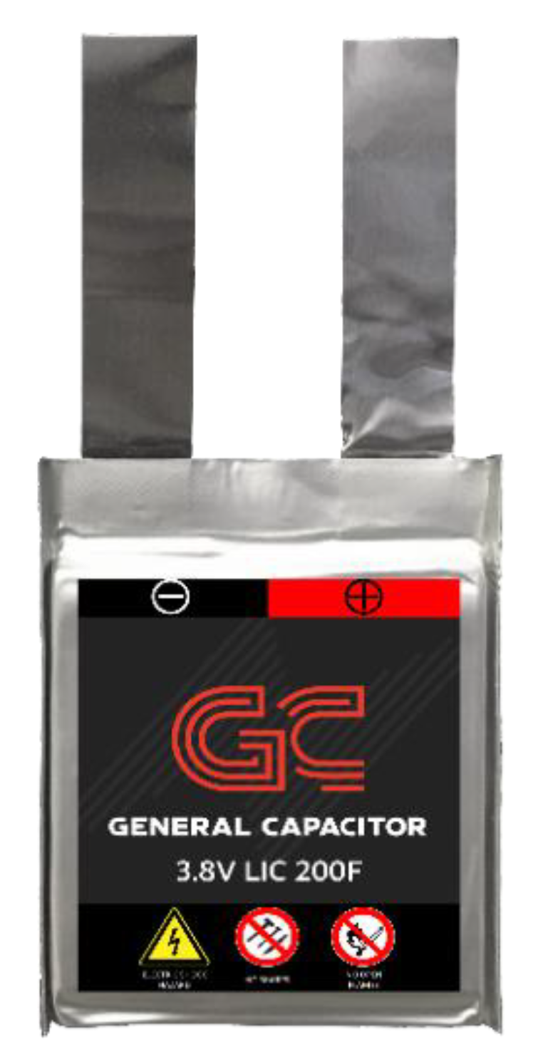
Figure 1. Lithium-ion capacitor (LIC) 200F pouch cell.
Batteries 05 00074 g001
Figure 2. Overview of abuse conditions and response of a LIC.
Batteries 05 00074 g002
Figure 3. LIC external short-circuit test.
Batteries 05 00074 g003
Figure 4. LIC overcharge test.
Batteries 05 00074 g004
Figure 5. Heat output generation during overcharge test.
Batteries 05 00074 g005
Figure 6. LIC nail-penetration test.
Batteries 05 00074 g006
Figure 7. LIC blunt crush test.
Batteries 05 00074 g007
Figure 8. LIC flat-plate crush test.
Batteries 05 00074 g008
Figure 9. LIC external heat test.
Batteries 05 00074 g009
Figure 10. (a) A swollen overcharged cell, (b) penetrated cell, (c,d) externally heated cell.
Batteries 05 00074 g010
Table 1. LIC specification.
ParametersSpecification
DimensionThickness = 4.5 mm,
Heights = 58 mm, Width = 48 mm
Weight16 g
Specific Power6 kW/kg
Specific Energy14 Wh/g
Voltage Range2.2–3.8 V
Maximum Voltage4.0 V
Capacitance200 F