Article

Improved Discharge Capacity of Zinc Particles by Applying Bismuth-Doped Silica Coating for Zinc-Based Batteries

1
Department of Materials Processing, University of Bayreuth, 95447 Bayreuth, Germany
2
Keylab Glass Technology, University of Bayreuth, 95447 Bayreuth, Germany
3
Department of Functional Materials, Bayerisches Zentrum für Batterietechnik (BayBatt), Zentrum für Energietechnik (ZET), University of Bayreuth, 95447 Bayreuth, Germany
*
Author to whom correspondence should be addressed.
Batteries 2019, 5(1), 32; https://doi.org/10.3390/batteries5010032
Submission received: 11 January 2019 / Revised: 8 March 2019 / Accepted: 11 March 2019 / Published: 14 March 2019

Abstract

:
Corrosion and discharge behavior of battery-grade zinc particles coated with a silica layer doped with bismuth was investigated and compared with untreated zinc powder. Electrochemical investigations were carried out in half-cell configuration. The electrolyte was 6 M KOH in excess. Coated zinc particles provided a discharge capacity of 737 mAh g−1 (89.9% DoD) versus 633 mAh g−1 (77.2% DoD) of untreated zinc particles after a dwell time of 1 h in KOH. The silica coating reduced the direct contact of the zinc surface with the electrolyte and thus minimized the hydrogen evolution reaction, which led to an increased discharge capacity. Additionally, bismuth doping enhanced conductivity within the silica coating and increased zinc utilization. Those coated zinc particles inhibited corrosion, i.e., corrosion efficiency reached 87.9% compared to uncoated zinc. Additionally, the coating achieved a capacity retention of 90.9% (670 mAh g−1) after 48 h dwell time in 6 M KOH. The coatings were prepared by sol-gel technology and characterized by Fourier transform infrared spectroscopy (FTIR), X-ray diffractometry (XRD), X-ray photoelectron spectroscopy (XPS), scanning electron microscopy (SEM), and Brunauer-Emmett-Teller (BET) surface determination.

1. Introduction

Through the worldwide expansion of renewable energies, the development of energy storage technologies has become an essential part of research and development activities nowadays. In particular, electrochemical storage systems such as batteries are in focus. Due to their long cycle life and high specific energy density, mainly Li-ion batteries are used today to store energy electrically. However, they also have disadvantages such as use of toxic materials, restricted resource availability, high costs, and safety problems due to the use of inflammable solvents and electrolytes. Consequently, research is increasingly being focused on alternative battery systems like metal-air batteries [1,2,3]. Among metal-air batteries, the zinc-air battery shows significant advantages such as high specific energy (1350 Wh kg−1), low costs, high availability of raw materials, good material recyclability, and safety [4,5,6,7,8,9]. Despite these beneficial properties, zinc-air batteries are not preferred as rechargeable but as primary batteries, especially in hearing aids, due to their low cycle life [4,10,11]. Especially the zinc anode does not meet the requirements for secondary zinc-air batteries due to degradation mechanisms such as dendritic growth, shape change, and passivation [12,13,14]. Various measures such as modifications of the electrolyte, addition of composites, and functional coatings of zinc were investigated to overcome these limitations recently [9,15,16,17,18,19,20,21,22,23].
Corrosion of zinc in the alkaline electrolyte affects both, primary and secondary zinc-air batteries, because zinc has a more negative reduction potential than hydrogen. This leads to evolution of hydrogen gas on the surface of the zinc particles. The hydrogen evolution reaction is expressed by Equation (1).
Zn + 2 H 2 O Zn ( OH ) 2 + H 2
Hydrogen evolution is an unwanted side reaction during discharge and during storage in the alkaline electrolyte. As a result, zinc is partially consumed during shelf life, i.e., the electrochemical efficiency is reduced [11,13].
One measure to overcome this problem is alloying of zinc. Lee et al. [24] demonstrated that alloying Zn with 2.5% indium and 7.5% nickel is favorable to raise the hydrogen overpotential and reduce the hydrogen evolution. However, alloying elements such as Pb, Ca, Hg, or Bi have also shown their ability to reduce the hydrogen evolution reaction [2,25]. In particular Bi is used as alloying element due to its higher environmental compatibility compared to Pb. Moreover, Zhang et al. [26] were able to show by adding Bi to zinc electrodes that the discharge capacity was increased due to an electronic network caused by the dispersed metallic Bi particles. Another promising strategy for minimizing self-discharge is the coating of zinc particles. Schmid et al. [27] applied a silica shell on zinc particles by chemical vapor deposition, resulting in a 20 nm thick Zn2SiO4 layer. This layer improved the discharge capacity of zinc due to reduced passivation and corrosion. Cho et al. [28] prepared zinc particles with a Li2O-2B2O3 coating, thus increasing discharge capacity and decreasing the hydrogen evolution reaction. Lee et al. [29] found that zinc particles with an Al2O3 coating were significantly more resistant to hydrogen evolution reaction than uncoated zinc particles mixed with Al2O3 powder.
In our previous paper, we showed that coating of zinc particles with a Bi2O3-Li2O-ZnO glass is able to reduce the passivation of zinc during charging cycles due to effective immobilization of discharge products in the glass layer and formation of metallic bismuth and zinc phases, which form a conductive network spread over the glass coating [9]. In contrast to [27], our approach focuses on coating battery-grade zinc with a silica coating doped with bismuth by sol-gel technology. The silica coating prevents direct contact of the electrolyte with the zinc particle surface, thus minimizing the hydrogen evolution reaction. The bismuth doping increases the hydrogen overvoltage and consequently reduces the hydrogen evolution. Besides, it shall create an electronically conductive network in situ in the oxidized zinc phases in order to increase the discharge capacity. The combination of these materials is studied analytically and electrochemically with the aim of investigating its effect on discharge capacity, self-discharge, and capacity retention in KOH after dwell times of 1 and 48 h, respectively. A schematic illustration of this concept is provided in Figure 1.
The resulting coating was characterized by Fourier transform infrared spectroscopy (FTIR), X-ray diffractometry (XRD), X-ray photoelectron spectroscopy (XPS), scanning electron microscopy (SEM), and Brunauer-Emmett-Teller (BET) surface determination. Electrochemical analysis was performed by galvanostatic discharge analysis in half-cell configuration with excess electrolyte.

2. Experimental Setup

2.1. Synthesis of Zinc Composite Material

Battery-grade zinc alloy powder from Grillo Werke AG (as received: d50 = 30 μm; alloying agents were determined by ICP-OES: Pb 28 ppm, In 215 ppm, Bi 220 ppm; BET surface area: 0.0455 m2 g−1) was used with d ≥ 25 µm as reference material. The coating of zinc particles was carried out by a sol-gel process according to the following procedure: 10 g zinc powder was mixed with 23.98 g ethanol absolute (C2H5OH, Merck Millipore, Burlington, MA, USA), 11.07 g H2O and 5.48 g tetramethylammonium hydroxide solution (TMAH, (CH3)4NOH, Alfa Aesar, Ward Hill, MA, USA, 25 wt.% in methanol) for 10 min at room temperature. Subsequently, 2.08 g tetraethyl orthosilicate (TEOS, (C2H5O)4Si, Alfa Aesar, 99.9%) was added. For the bismuth-doped silica coating 0.1 or 0.21 g of bismuth-isopropoxide (Bi[OCH(CH3)2]3, Alfa Aesar) was added to the TEOS solution. The mixture was kept for 2 h under stirring at room temperature. Afterward, ethanol was slowly evaporated at 80 °C. The coated zinc powder was then washed with ethanol absolute until the filtrate became colorless. Finally, the coated zinc particles were dried at 80 °C for 24 h.

2.2. Analytical Methods

Polycondensation of silica on the zinc particles was confirmed using Fourier transform infrared spectroscopy (FTIR, Vertex 70, Bruker Corporation, Billerica, MA, USA) in the wave number range from 600 to 3600 cm−1. Furthermore, X-ray diffraction (X’Pert-MPD System PW 3040/00, Philips Analytical X-ray B.V., EA Almelo, The Netherlands) was used to identify bismuth phases in the coating. Diffraction patterns were acquired with Cu Kα radiation at scattering angles from 20° to 65° in increments of 0.02°. In addition, X-ray photoelectron spectroscopy (XPS, PHI 5000 VersaProbe II, Physical Electronics GmbH, Ismaning, Germany) was used to determine the chemical state of Bi in the coating. For surface analysis, monochromatic Al Kα X-rays (1486.6 eV) were used. The X-ray beam voltage was set to 15 kV with a power of 50 W. The pass energy was 26 eV with a step time of 50 ms and a step size of 0.05 eV. Scanning electron microscopy (SEM, JSM-840A, JEOL, Tokyo, Japan) in combination with energy dispersive X-ray spectroscopy (EDX, INCA 4.05 EDS, Oxford Instruments Microanalysis Limited, Abingdon, UK) was used to determine the coating quality and the structure of zinc particles. In addition, the layer thickness of the coating was determined graphically using SEM pictures. Hence, coated zinc particles were embedded in epoxy resin, and cross sections were prepared by polishing. Further, BET surface area was calculated from nitrogen adsorption isotherms (ASAP 2020, Micromeritics, Norcross, GA, USA).

2.3. Electrochemical Characterization

Electrochemical measurements were performed in a half-cell configuration (Potentiostat Bio-Logic, VMP3, Seyssinet-Pariset, France). The electrode material (100 mg) was placed as powder bed on a copper conductor. The electrolyte was 6 M KOH was added in high excess (80 mL in a 100 mL glass beaker). An Ag/AgCl electrode (3.5 M KCl) and a platinum plate (3 × 3 cm) were applied as reference or counter electrode, respectively. Galvanostatic polarization was carried out between −1.45 and −1.65 V vs. Ag/AgCl reference electrode at 0.1 mVs−1 in order to analyze the corrosion behavior of uncoated and coated zinc particles. Additionally, electrical impedance spectroscopy (EIS) with an AC voltage (amplitude 20 mV) in a frequency range from 20 mHz to 1 MHz was applied to investigate the anode before discharge. The internal resistance, Ri, was calculated from the real part of the complex impedance in Nyquist plots. In order to characterize the self-discharge behavior, the zinc particles were discharged after 1 h dwell time in 6 M KOH at room temperature, and after 48 h dwell time, respectively. The anode was galvanostatically discharged up to a cell cutoff voltage of U = −0.9 V vs. Ag/AgCl at a current rate of C/20.

3. Results and Discussion

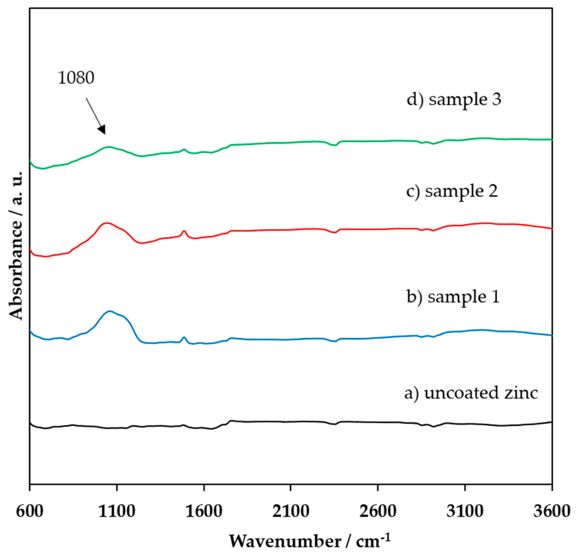
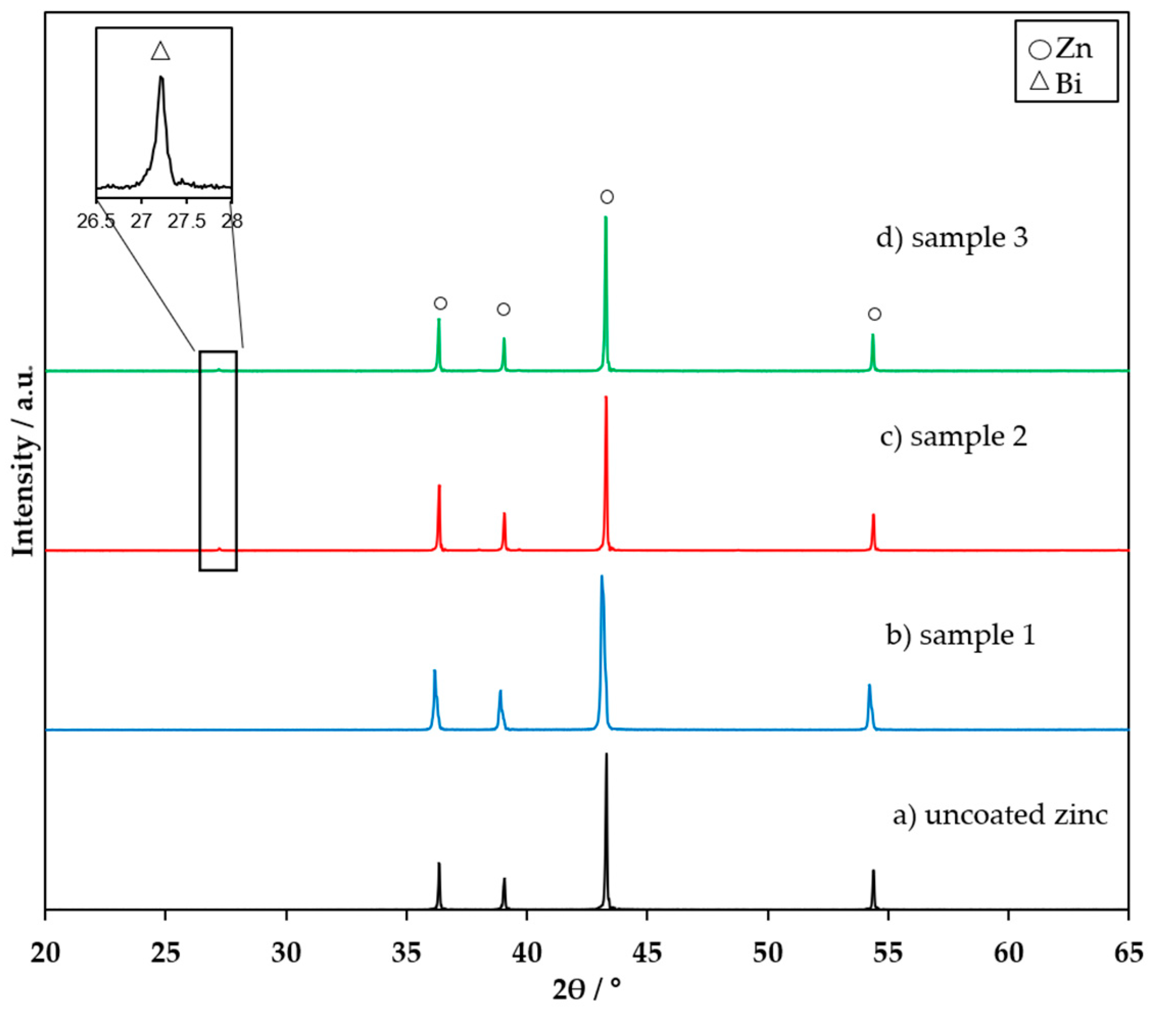
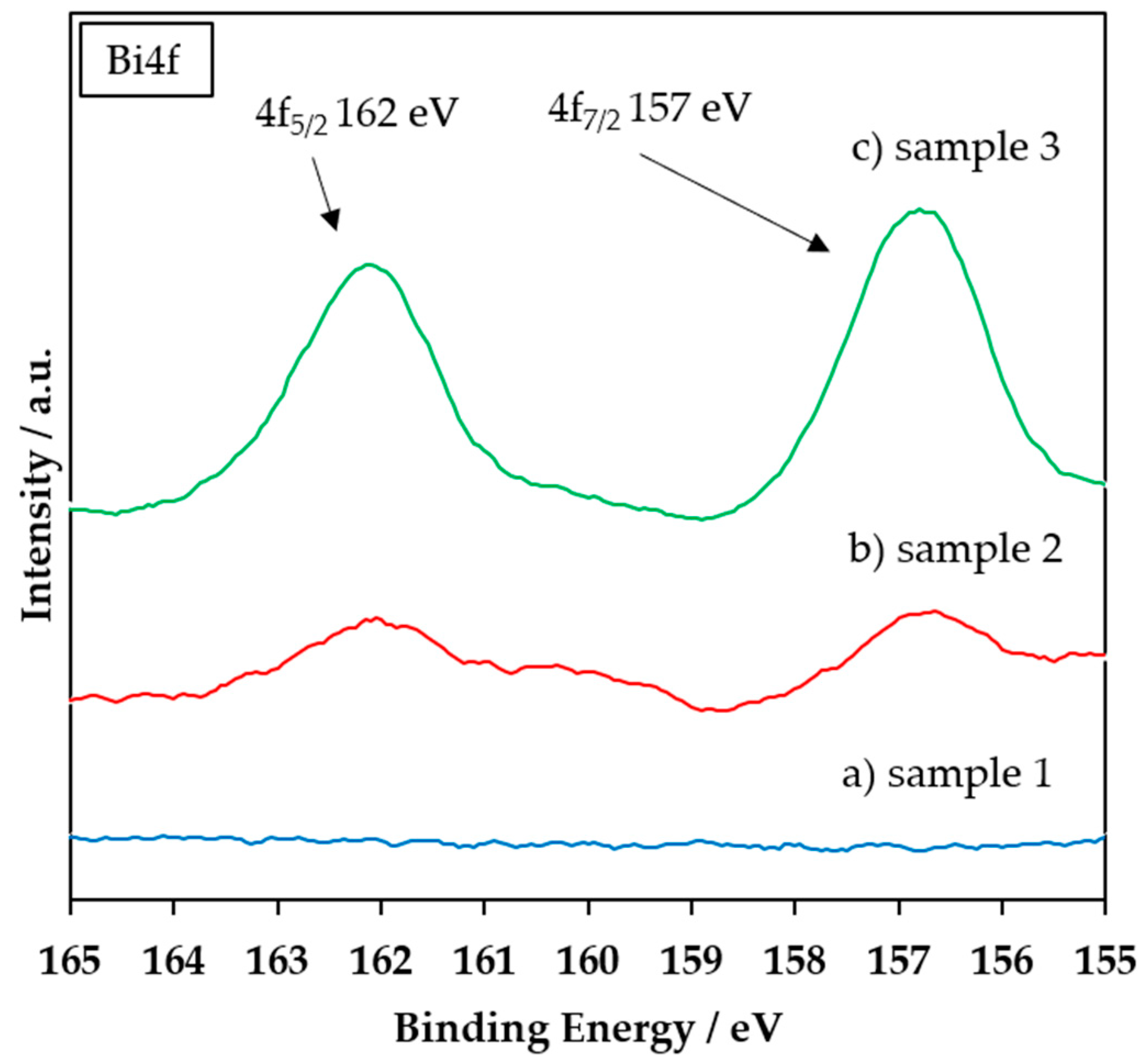
3.1. FTIR, XRD, and XPS Characterization of the Coating

In order to investigate silica coating formation and doping of the same with Bi, the particles were analyzed using FTIR, XRD, and XPS analyses. Table 1 provides a schematic overview of the characteristics of the investigated coatings, consecutively referenced as samples 1–3. Figure 2 compares the FTIR spectra of uncoated and coated zinc.
The FTIR spectra in Figure 2 show a broad peak around 1080 cm−1 for all coated samples in contrast to uncoated zinc. This peak is assigned to Si–O–Si bonds, representing the silica framework [30]. Thus, we assumed that indeed polycondensation of silica deposits on the zinc surface was achieved. Furthermore, we observed that the addition of bismuth did not affect silica formation. However, bismuth is inactive under infrared radiation. Therefore, it is indiscernible by FTIR. Instead, Bi is X-ray sensitive while silica is X-ray amorphous, which allows clear recognition of Bi from X-ray diffraction. Figure 3 illustrates the XRD patterns of uncoated and coated zinc (samples 1–3).
Characteristic XRD peaks for hexagonal zinc, found at 2θ = 43.23°, 36.29°, 38.94°, and 53.33°, are fully expressed for uncoated and coated zinc. Sample 2 and sample 3 show a tiny peak at 27.16°. This reflex is assigned to rhombohedral Bi. Due to the low concentration of Bi, Bi doping was confirmed by XPS measurements. The result is presented in Figure 4.
According to the Bi 4f spectra of sample 2 and sample 3, peaks for metallic Bi appear at 157 and 162 eV [31]. The presence of these Bi metal peaks demonstrates that the doping of the silica coating with metallic bismuth for sample 2 and sample 3 was successful. These peaks at 157 and 162 eV were not found in sample 1 as it is a pure silica coating. Therefore, it can be excluded that the Bi found in sample 2 and sample 3 originated from the alloying of zinc raw material.

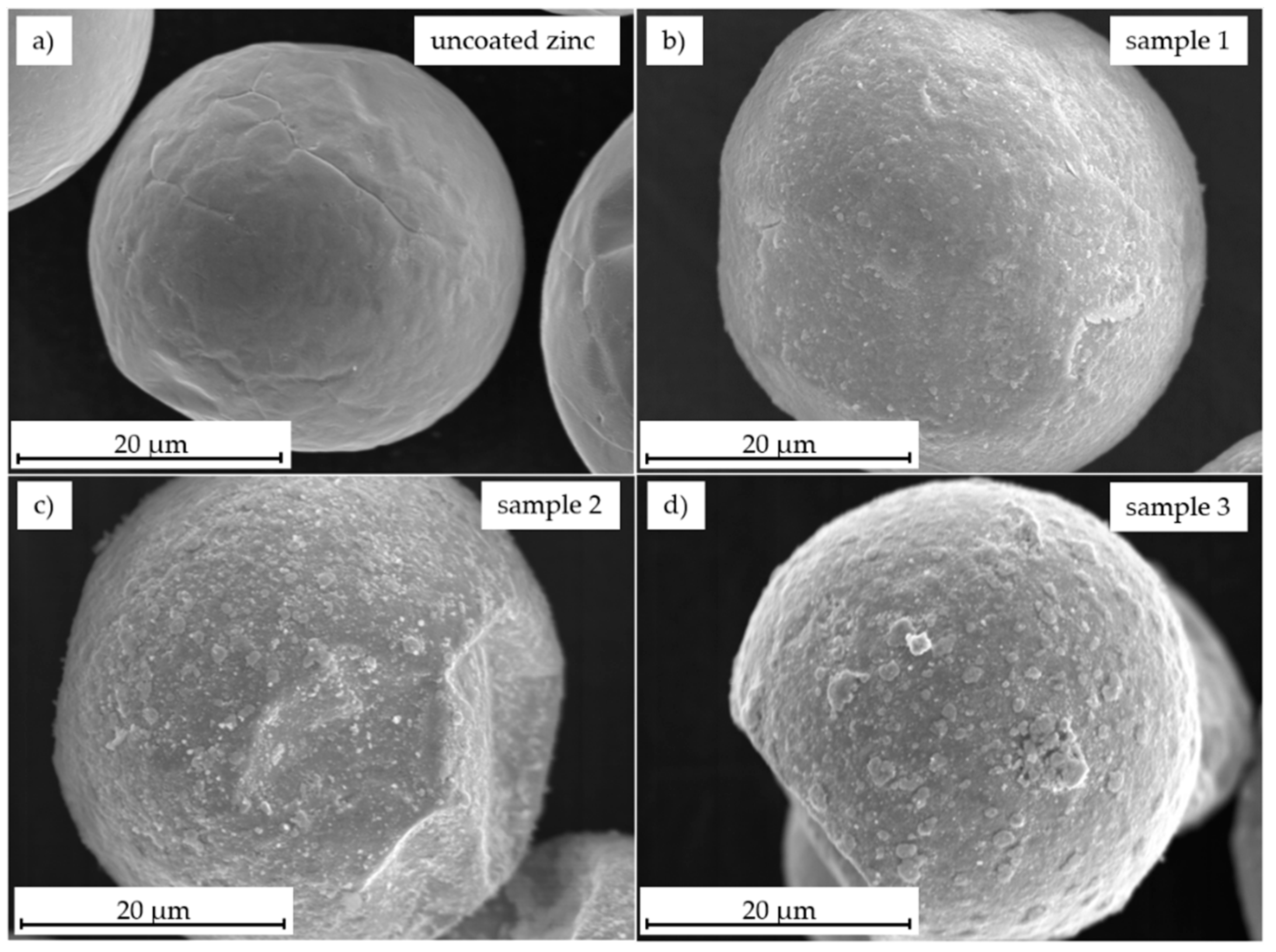
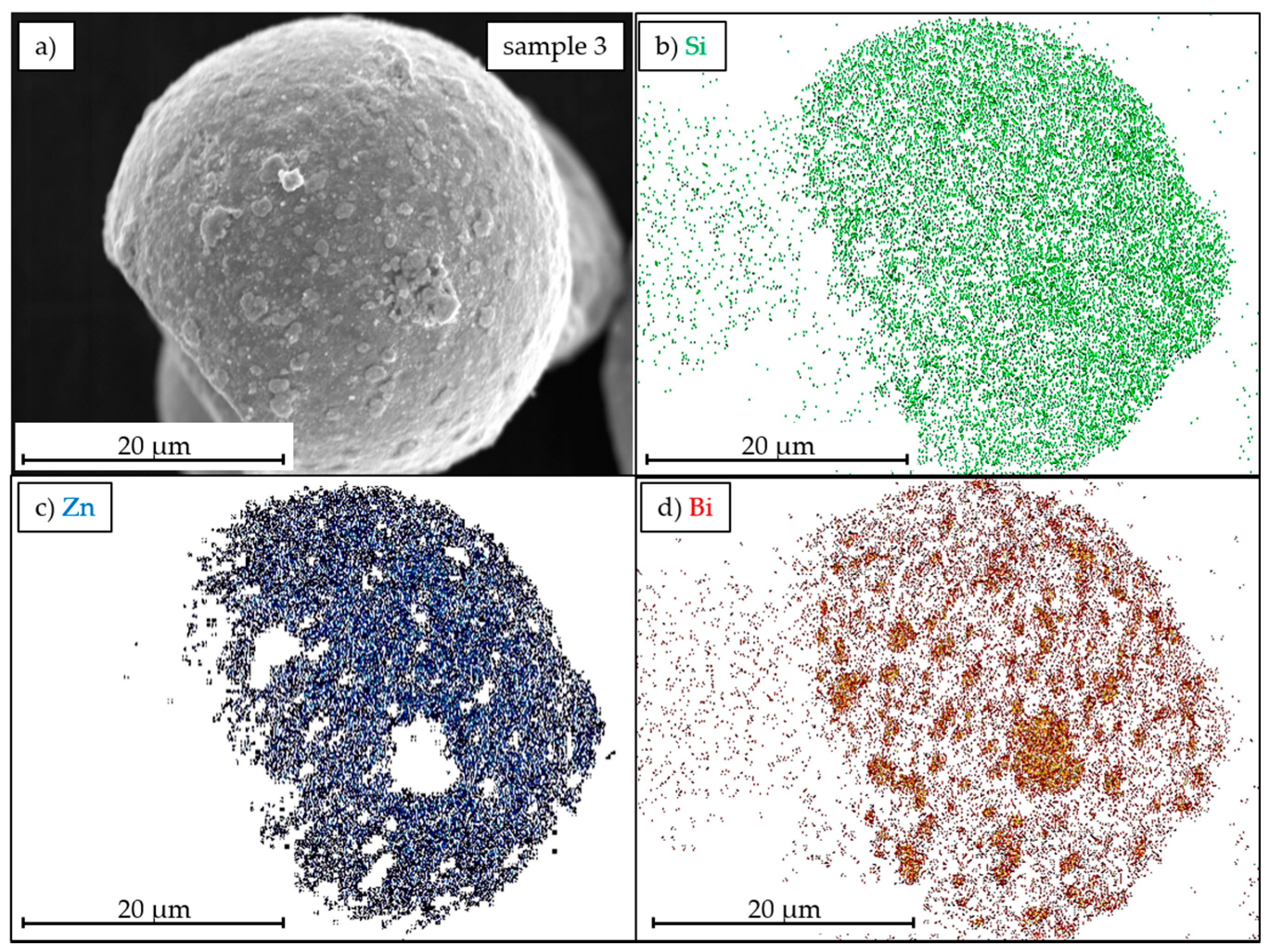
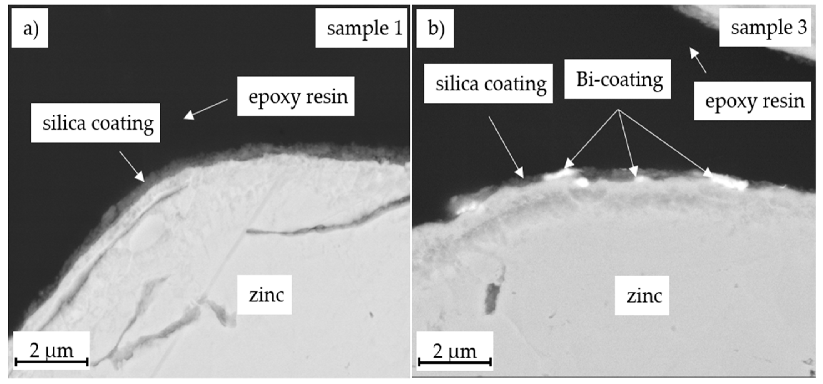
3.2. Morphology Characterization

An indication for the coating quality is the homogeneity of coating and an even distribution of bismuth on the zinc surface. SEM micrographs were taken to study the coating morphology. The SEM images of the uncoated and coated zinc powders are shown in Figure 5.
Figure 5b shows a homogeneous and uniform particle surface. There are no uncoated spots detectable, i.e., a smooth silica coating was achieved. In contrast, the coatings with Bi doping show a rougher surface as illustrated in Figure 5c (sample 2) and Figure 5d (sample 3). Increasing the bismuth content (Figure 5d, sample 3) obviously led to an increase in surface roughness. Agglomerates were probably formed, as indicated in Figure 5d. The increase in roughness is supported by the BET measurements presented in Table 1 inasmuch as the BET surface area increases from (0.257 ± 0.003) m2 g−1 of sample 1 to (0.327 ± 0.003) m2 g−1 for sample 2, and finally to (0.448 ± 0.015) m2 g−1 for sample 3. Nevertheless, we assume that a homogeneous silica coating entirely covers all coated samples.
In order to evaluate the elemental distribution of Si and Bi on the zinc surface, EDX mappings were prepared for sample 3, in addition to the SEM micrograph in Figure 5d. The mappings for, Si, Zn, and Bi are presented in Figure 6b–d.
The distribution of elemental Si in Figure 6b indicates that silicon is distributed uniformly over the surface of the zinc particle, confirming the assumption of a homogeneous, closed silica layer. Figure 6d however shows spots of aggregated Bi in the micrometer scale. Nevertheless, Bi is roughly present all over the zinc surface. Those Bi clusters may be caused due to the deposition process. As the Bi precursor is a powder and insoluble in the used solvent, the deposition of Bi on zinc is a solid-state reaction and most likely dependent on the initial particle size distribution.
In order to investigate coating thickness and distribution of Bi inside the silica layer, cross-sections of sample 1 and sample 3 were prepared. The layer thickness was determined graphically by using SEM images and measuring at seven points along the layer. Mean value and standard deviation were calculated from these measurements. The SEM images are presented in Figure 7.
Figure 7a shows the pure silica coating (sample 1). The layer is evenly thick with an average thickness of (286 ± 23) nm. Figure 7b shows the silica coating with Bi doping (sample 3). Again, an evenly thick silica coating is observed. The bright dots in the coating indicate Bi aggregates. The Bi aggregates are placed both, on the surface and inside the silica layer. Thus, we consider the doping of the silica coating with Bi as a success even though a more homogeneous distribution would have been favored.

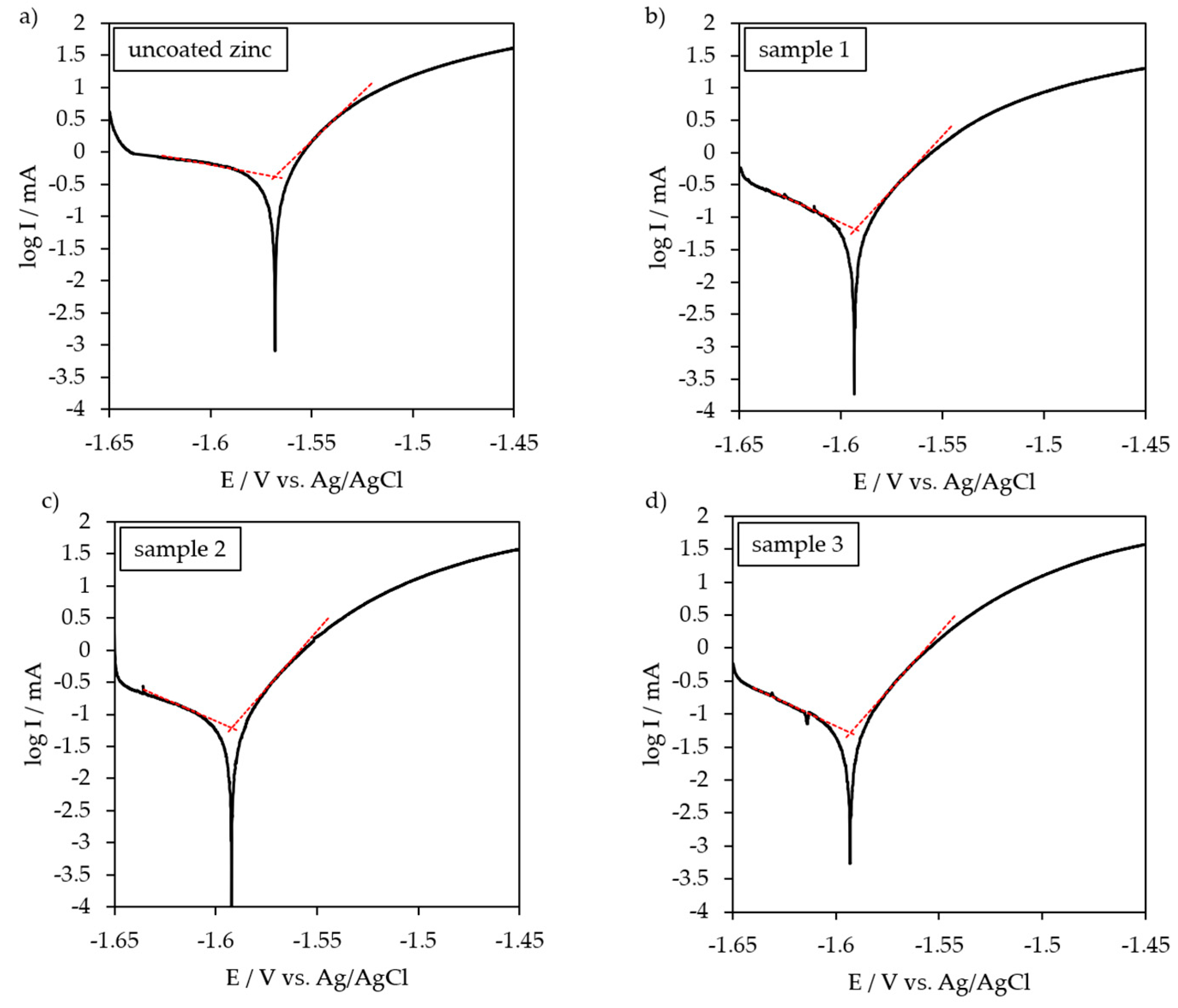
3.3. Potentio-Dynamic Polarization Behavior

In order to study the influence of silica coating and additional Bi doping on the corrosion behavior of zinc particles, galvanostatic polarization was used. Polarization curves for uncoated and coated zinc in 6 M KOH are presented in Figure 8. The corrosion potential (Ecorr) and corrosion current (Icorr) were derived from Figure 8 by extrapolation of anodic and cathodic Tafel lines. Additionally, the protective efficiency of the coatings was calculated according to Equation (2),
η = 100 % ( I corr uncoated I corr coated ) I corr uncoated ,
where I corr uncoated and I corr coated are the corrosion currents of uncoated and coated zinc materials, respectively. The results are summarized in Table 2.
The uncoated zinc powder shows a corrosion potential of −1.568 V vs. Ag/AgCl (Figure 8a) and a corrosion current of 419.8 µA (Table 2). Sample 1 shows a shift in corrosion potential toward a more negative potential (−1.593 V), as indicated in Figure 8b. In addition, the corrosion current was reduced to 65.7 µA (Table 2).
The doping of silica coating with bismuth (sample 2 and sample 3) had no effect on the corrosion potential. However, the bismuth coating decreased the corrosion current of sample 2 and sample 3 to 61.2 and 50.9 µA, respectively. The results indicated that corrosion of zinc particles in 6 M KOH was effectively reduced by the coating as hydrogen evolution was suppressed. We assume that the unwanted side reaction of zinc and electrolyte was partially suppressed by the silica/Bi coating. Therefore, the layer acted like a passivation barrier and prevented direct contact of the zinc surface with the electrolyte. Additionally, Bi has a high hydrogen overpotential, which reduced hydrogen evolution [26].
In summary, the combination of silica coating and bismuth doping achieved in the best case a protective efficiency of 87.9% (see sample 3 in Table 2). Based on these results, a lower self-discharge and thus an improved zinc utilization of zinc particles coated with Bi-doped silica is expected.

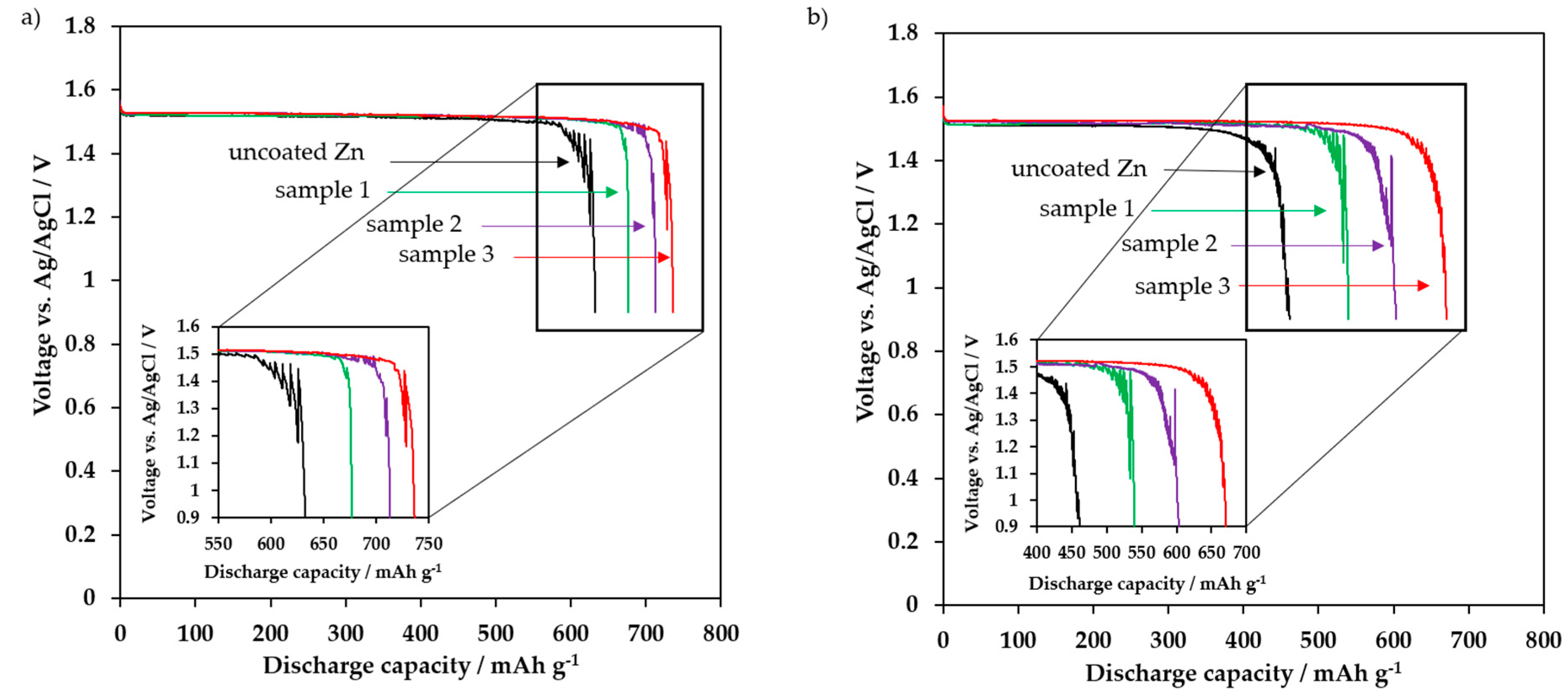
3.4. Electrochemical Discharge Behavior

To demonstrate the reduced self-discharge and the expected increase in discharge capacity, the discharge behavior was investigated in a half-cell configuration. The samples were dwelled for either 1 or 48 h in 6 M KOH before being completely discharged to a cutoff voltage of 0.9 V vs. Ag/AgCl. In order to check the protective efficiency of the coating, the capacity retention (Cr) was calculated using Equation (3)
C r = 100 · c 48 h   dwell   time c 1 h   dwell   time ,
where C48h dwell time and C1h dwell time are the discharge capacities after 48 and 1 h dwell times, respectively. The discharge curves are shown in Figure 9a,b. The corresponding discharge capacities and capacity retentions are summarized in Table 3. The discharge capacity was related to the total electrode mass, i.e., mass of zinc mass plus mass of coating. However, the mass of coating at a layer thickness of (286 ± 23) nm was almost negligible compared to mass of the particle.
After 1 h dwell time (Figure 9a) uncoated zinc powder had a specific discharge capacity of 633 mAh g−1, which corresponds to a zinc utilization of 77.2%, in relation to the theoretical specific capacity of zinc. Sample 1 showed a discharge capacity of 677 mAh g−1, which is already equivalent to a zinc utilization of 82.6%. The additional doping of the coating with bismuth increased the discharge capacity for sample 2 and sample 3 to 713 mAh g−1 and 737 mAh g−1, respectively. As a result, zinc utilization of samples 2 and 3 rose to 87.0% and 89.9%, respectively.
The enhanced discharge capacities of the coated zinc particles confirm the Tafel results in Figure 8 and Table 2. The coating reduced self-discharge of the active material due to decreased hydrogen evolution, thus preventing premature zinc oxide formation, i.e., preventing zinc from becoming inactive. As a result, more active material was available for the electrochemical discharge reaction. Furthermore, the increased discharge capacity of Bi-doped coatings was achieved by improved conductivity of the electrode. Table 4 illustrates the internal resistance before the discharge. Related Nyquist plots are presented in the Supplementary File, see Figure S1.
According to Table 4, the coatings do not clearly change the internal resistance. Nevertheless, a slight decrease from (1.09 ± 0.07) Ω for uncoated zinc and (1.10 ± 0.05) Ω for silica coated zinc (sample 1) toward (0.98 ± 0.05) Ω for sample 2 and (0.97 ± 0.03) Ω for sample 3 was seen, probably due to the increased layer conductivity in the presence of metallic bismuth, which in turn increased discharge capacities of sample 2 and sample 3.
After a dwell time of 48 h (Figure 9b) both, uncoated zinc powder and the coated zinc powder, showed a decrease in discharge capacity due to extended self-discharge in 6 M KOH. Uncoated zinc had a specific discharge capacity of 461 mAh g−1 (56.2% DoD), which corresponded to a capacity retention of 72.8%. Silica-coated zinc (sample 1) showed a discharge capacity of 540 mAh g−1 (65.9% DoD) and a capacity retention of 79.8%. The increased capacity retention of sample 1 indicated that the coating acts as a protective barrier during dwelling in KOH, thus reducing the self-discharge of the zinc anode. This result can be improved by a Bi-doped silica coating due to an increase in the hydrogen overvoltage. Sample 2 and sample 3 show discharge capacities of 603 mAh g−1 (73.5% DoD) and 670 mAh g−1 (81.7% DoD), respectively, which in turn means a capacity retention of 84.6% or 90.9%, respectively.

4. Conclusions

Battery-grade zinc for zinc-air battery anodes corrode in alkaline electrolyte during shelf life and discharge. In order to reduce corrosion, those zinc particles were coated with silica by a wet-chemical sol-gel process in order to prevent the direct contact of the zinc surface with the electrolyte. Additionally, the coating was doped with bismuth to increase hydrogen overvoltage, electrical conductivity, and discharge capacity. We confirmed by FTIR, XRD, BET, and XPS that the zinc particles were coated entirely with a silica layer. SEM micrographs demonstrated a homogeneous coating with a layer thickness of about (286 ± 23) nm. In contrast, Bi-doped coatings were rougher with large aggregates of Bi due to solid-state reaction. However, improved homogeneity of Bi is considered favorable for battery application. The silica coating with higher amount of Bi reduced hydrogen evolution and achieved a protective efficiency of 87.9%. That means the parasitic side reaction was suppressed, and the DoD of coated zinc after 1 h dwelling in 6 M KOH was increased from 77.2% to 89.9%. Due to the protective effect of the coating against the electrolyte, an enhanced discharge capacity was achieved, even if the dwell time in 6 M KOH was increased to 48 h. The capacity retention was more than 90% compared to only 72.8% for uncoated zinc.
In conclusion, the combined strategy with a protective silica coating and doping with electrically conductive Bi, improved discharge capacity and capacity retention significantly compared to as-received battery-grade zinc, i.e., it is a promising material combination for zinc anodes in zinc-based batteries.
Further studies are in preparation with the aim to reduce passivation and corrosion of rechargeable zinc-air batteries by combining glass-coated zinc particles as described in [9] with the herein presented work on silica/Bi coating.

Supplementary Materials

The following are available online at https://www.mdpi.com/2313-0105/5/1/32/s1, Figure S1: a) Exemplary Nyquist plots of uncoated zinc, sample 1, sample 2 and sample 3. b–d) Zoom on high-frequency region of EIS to determine Ri from three measurements for sample 1, sample 2, and sample 3.

Author Contributions

T.M. performed the experiments and wrote the paper; T.M. and A.R. analyzed the data; R.M., A.R., and T.G. provided guidance and helped in manuscript preparation. All authors discussed the data and decided on next steps.

Funding

This research was funded by Bundesministerium für Bildung und Forschung within the project “PrintEnergy” (grant number 13XP5015A). The APC was funded by the German Research Foundation (DFG) and the University of Bayreuth in the funding program Open Access Publishing.

Acknowledgments

Financial support is gratefully acknowledged. The authors would like to thank the project partners at VARTA Microbattery GmbH and Grillo Werke AG. The authors thank Angelika Mergner from the Chair of Functional Materials (University of Bayreuth) for sample preparation as well as Sebastian Lehmann and Lukas Zielbauer from the Chair of Materials Processing (University of Bayreuth) for performing XPS measurements.

Conflicts of Interest

The authors declare no conflicts of interest.

References

  1. Lu, W.; Xie, C.; Zhang, H.; Li, X. Inhibition of Zinc Dendrite Growth in Zinc-Based Batteries. ChemSusChem 2018, 11, 3996–4006. [Google Scholar] [CrossRef] [PubMed]
  2. Yi, J.; Liang, P.; Liu, X.; Wu, K.; Liu, Y.; Wang, Y.; Xia, Y.; Zhang, J. Challenges, mitigation strategies and perspectives in development of zinc-electrode materials and fabrication for rechargeable zinc-air batteries. Energy Environ. Sci. 2018, 11, 3075–3095. [Google Scholar] [CrossRef]
  3. Parker, J.F.; Chervin, C.N.; Pala, I.R.; Machler, M.; Burz, M.F.; Long, J.W.; Rolison, D.R. Rechargeable nickel-3D zinc batteries: An energy-dense, safer alternative to lithium-ion. Science 2017, 356, 415–418. [Google Scholar] [CrossRef] [PubMed]
  4. Pei, P.; Wang, K.; Ma, Z. Technologies for extending zinc-air battery’s cyclelife: A review. Appl. Energy 2014, 128, 315–324. [Google Scholar] [CrossRef]
  5. Fu, J.; Cano, Z.P.; Park, M.G.; Yu, A.; Fowler, M.; Chen, Z. Electrically rechargeable zinc-air batteries: Progress, challenges, and perspectives. Adv. Mater. 2017, 29, 1604685. [Google Scholar] [CrossRef] [PubMed]
  6. Xu, M.; Ivey, D.G.; Xie, Z.; Qu, W. Rechargeable Zn-air batteries: Progress in electrolyte development and cell configuration advancement. J. Power Sources 2015, 283, 358–371. [Google Scholar] [CrossRef]
  7. Larsson, F.; Rytinki, A.; Ahmed, I.; Albinsson, I.; Mellander, B.-E. Overcurrent Abuse of Primary Prismatic Zinc-air Battery Cells Studying Air Supply Effects on Performance and Safety Shut-Down. Batteries 2017, 3, 1. [Google Scholar] [CrossRef]
  8. Garcia, G.; Schuhmann, W.; Ventosa, E. A Three-Electrode, Battery-Type Swagelok Cell for the Evaluation of Secondary Alkaline Batteries: The Case of the Ni–Zn Battery. ChemElectroChem 2016, 3, 592–597. [Google Scholar] [CrossRef]
  9. Michlik, T.; Schmid, M.; Rosin, A.; Gerdes, T.; Moos, R. Mechanical Coating of Zinc Particles with Bi2O3-Li2O-ZnO Glasses as Anode Material for Rechargeable Zinc-Based Batteries. Batteries 2018, 4, 12. [Google Scholar] [CrossRef]
  10. Ma, H.; Wang, B.; Fan, Y.; Hong, W. Development and Characterization of an Electrically Rechargeable Zinc-Air Battery Stack. Energies 2014, 7, 6549–6557. [Google Scholar] [CrossRef] [Green Version]
  11. Franke-Lang, R.; Arlt, T.; Manke, I.; Kowal, J. X-ray tomography as a powerful method for zinc-air battery research. J. Power Sources 2017, 370, 45–51. [Google Scholar] [CrossRef]
  12. Stamm, J.; Varzi, A.; Latz, A.; Horstmann, B. Modeling nucleation and growth of zinc oxide during discharge of primary zinc-air batteries. J. Power Sources 2017, 360, 136–149. [Google Scholar] [CrossRef] [Green Version]
  13. Lee, J.S.; Tai Kim, S.; Cao, R.; Choi, N.S.; Liu, M.; Lee, K.T.; Cho, J. Metal-air batteries with high energy density: Li–air versus Zn–air. Adv. Energy Mater. 2011, 1, 34–50. [Google Scholar] [CrossRef]
  14. Garcia, G.; Ventosa, E.; Schuhmann, W. Complete prevention of dendrite formation in Zn metal anodes by means of pulsed charging protocols. ACS Appl. Mater. Interfaces 2017, 9, 18691–18698. [Google Scholar] [CrossRef]
  15. Mainar, A.R.; Colmenares, L.C.; Grande, H.-J.; Blázquez, J.A. Enhancing the Cycle Life of a Zinc-air Battery by Means of Electrolyte Additives and Zinc Surface Protection. Batteries 2018, 4, 46. [Google Scholar] [CrossRef]
  16. Liu, Z.; Cui, T.; Pulletikurthi, G.; Lahiri, A.; Carstens, T.; Olschewski, M.; Endres, F. Dendrite-Free Nanocrystalline Zinc Electrodeposition from an Ionic Liquid Containing Nickel Triflate for Rechargeable Zn-Based Batteries. Angew. Chem. Int. Ed. 2016, 55, 2889–2893. [Google Scholar] [CrossRef]
  17. McBreen, J.; Gannon, E. Bismuth oxide as an additive in pasted zinc electrodes. J. Power Sources 1985, 15, 169–177. [Google Scholar] [CrossRef]
  18. Huang, H.; Gu, S.J.; Gan, Y.P.; Tao, X.Y.; Zhang, W.K. ZnO/ZnO-Bi2O3 Nanocomposite as an Anode Material for Ni-Zn Rechargeable Battery. Adv. Mater. Res. 2012, 396, 1725–1729. [Google Scholar] [CrossRef]
  19. Yuan, Y.F.; Yu, L.Q.; Wu, H.M.; Yang, J.L.; Chen, Y.B.; Guo, S.Y.; Tu, J.P. Electrochemical performances of Bi based compound film-coated ZnO as anodic materials of Ni-Zn secondary batteries. Electrochim. Acta 2011, 56, 4378–4383. [Google Scholar] [CrossRef]
  20. Stock, D.; Dongmo, S.; Miyazaki, K.; Abe, T.; Janek, J.; Schröder, D. Towards zinc-oxygen batteries with enhanced cycling stability: The benefit of anion-exchange ionomer for zinc sponge anodes. J. Power Sources 2018, 395, 195–204. [Google Scholar] [CrossRef]
  21. Stock, D.; Dongmo, S.; Walther, F.; Sann, J.; Janek, J.; Schroder, D. Homogeneous Coating with an Anion-Exchange Ionomer Improves the Cycling Stability of Secondary Batteries with Zinc Anodes. ACS Appl. Mater. Interfaces 2018, 10, 8640–8648. [Google Scholar] [CrossRef]
  22. Clark, S.; Latz, A.; Horstmann, B. Rational Development of Neutral Aqueous Electrolytes for Zinc-Air Batteries. ChemSusChem 2017, 10, 4735–4747. [Google Scholar] [CrossRef]
  23. Ingale, P.; Sakthivel, M.; Drillet, J.F. Test of Diethylmethylammonium Trifluoromethanesulfonate Ionic Liquid as Electrolyte in Electrically Rechargeable Zn/Air Battery. J. Electrochem. Soc. 2017, 164, 5224–5229. [Google Scholar] [CrossRef]
  24. Lee, C.W.; Sathiyanarayanan, K.; Eom, S.W.; Yun, M.S. Novel alloys to improve the electrochemical behavior of zinc anodes for zinc/air battery. J. Power Sources 2006, 160, 1436–1441. [Google Scholar] [CrossRef]
  25. Huot, J.Y.; Boubour, E. Electrochemical performance of gelled zinc alloy powders in alkaline solutions. J. Power Sources 1997, 65, 81–85. [Google Scholar] [CrossRef]
  26. Zhang, C.; Wang, J.M.; Zhang, L.; Zhang, J.Q.; Cao, C.N. Study of the performance of secondary alkaline pasted zinc electrodes. J. Appl. Electrochem. 2001, 31, 1049–1054. [Google Scholar] [CrossRef]
  27. Schmid, M.; Willert-Porada, M. Electrochemical behavior of zinc particles with silica based coatings as anode material for zinc air batteries with improved discharge capacity. J. Power Sources 2017, 351, 115–122. [Google Scholar] [CrossRef]
  28. Cho, Y.D.; Fey, G.T.K. Surface treatment of zinc anodes to improve discharge capacity and suppress hydrogen gas evolution. J. Power Sources 2008, 184, 610–616. [Google Scholar] [CrossRef]
  29. Lee, S.M.; Kim, Y.J.; Eom, S.W.; Choi, N.S.; Kim, K.W.; Cho, S.B. Improvement in self-discharge of Zn anode by applying surface modification for Zn-air batteries with high energy density. J. Power Sources 2013, 227, 177–184. [Google Scholar] [CrossRef]
  30. Lucovsky, G.; Yang, J.; Chao, S.S.; Tyler, J.E.; Czubatyj, W. Oxygen-bonding environments in glow-discharge-deposited amorphous silicon-hydrogen alloy films. Phys. Rev. B 1983, 28, 3225. [Google Scholar] [CrossRef]
  31. Chastain, J.; Moulder, J.F.; Stickle, W.F.; Sobol, P.E.; Bomben, K.D. Handbook of X-ray Photoelectron Spectroscopy: A Reference Book of Standard Spectra for Identification and Interpretation of XPS Data; Perkin-Elmer Corporation: Eden Prairie, MN, USA, 1992; pp. 190–191. [Google Scholar]
Figure 1. Schematic illustration of (a) uncoated zinc and (b) coated zinc with a protective silica layer doped with Bi.
Batteries 05 00032 g001
Figure 2. FTIR spectra of (a) uncoated zinc and coated zinc particles, referenced as (b) sample 1, (c) sample 2, and (d) sample 3 according to Table 1.
Batteries 05 00032 g002
Figure 3. X-ray diffraction patterns of (a) uncoated zinc and coated zinc: (b) Sample 1, (c) sample 2, and (d) sample 3. The identified diffraction peaks are assigned to Zn (ICDD-PDF-4-2018-00-004-0831) and rhombohedral Bi (ICDD-PDF-4-2018-01-071-4642).
Batteries 05 00032 g003
Figure 4. Bi 4f X-ray photoelectron spectroscopy (XPS) of (a) sample 1, (b) sample 2, and (c) sample 3.
Batteries 05 00032 g004
Figure 5. SEM micrographs (secondary electron detector) of (a) uncoated zinc and coated zinc: (b) Sample 1, (c) sample 2, and (d) sample 3.
Batteries 05 00032 g005
Figure 6. SEM micrographs (secondary electron detector) of (a) sample 3, including the energy dispersive X-ray spectroscopy (EDX) element maps for (b) Si, (c) Zn, and (d) Bi.
Batteries 05 00032 g006
Figure 7. SEM micrographs (back scattered electron detector) of cross sections of zinc coated with (a) pure silica layer (sample 1) and coated with (b) silica layer doped with Bi (sample 3).
Batteries 05 00032 g007
Figure 8. Polarization curves of (a) uncoated zinc and coated zinc in 6 M KOH: (b) Sample 1, (c) sample 2, and (d) sample 3.
Batteries 05 00032 g008
Figure 9. Discharge curves of uncoated and coated zinc powder (samples 1–3) after a dwell time of (a) 1 h and (b) 48 h in 6 M KOH.
Batteries 05 00032 g009
Table 1. Characteristics of investigated coated zinc particles (samples 1–3) including amount of educts and Brunauer-Emmett-Teller (BET) surface areas.
ParameterValue
Sample NameSample 1Sample 2Sample 3
Schematic illustration Batteries 05 00032 i001 Batteries 05 00032 i002 Batteries 05 00032 i003
Input mass:
Zinc powder/g101010
Si Precursor/g2.08 (   0.28   Si ) 2.08 (   0.28   Si ) 2.08 (   0.28   Si )
Bi Precursor/g-0.10 (   0.05   Bi ) 0.21 (   0.11   Bi )
BET surface area/m2 g−1 0.257 ± 0.0030.327 ± 0.0030.448 ± 0.015
Table 2. Corrosion parameters and protective efficiency of uncoated and coated zinc powders.
Sample NameParameter
Ecorr in V vs. Ag/AgClIcorr in µAη in %
Uncoated zinc−1.568419.8-
Sample 1−1.59365.784.3
Sample 2−1.59261.285.4
Sample 3−1.59350.987.9
Table 3. Discharge capacities, zinc utilization (DoD) after 1 and 48 h dwell times, and capacity retention of uncoated and coated zinc (samples 1–3).
Sample NameParameter
c (mAh g−1)
1 h Dwell Time
DoD in %
1 h Dwell Time
c (mAh g−1)
48 h Dwell Time
DoD in %
48 h Dwell Time
Capacity Retention in %
Uncoated zinc63377.246156.272.8
Sample 167782.654065.979.8
Sample 271387.060373.584.6
Sample 373789.967081.790.9
Table 4. Internal resistance, Ri, as determined in Section 2.3 for uncoated and coated zinc (samples 1–3) after a dwell time of 1 h in 6 M KOH.
ParameterSample Name
Uncoated ZincSample 1Sample 2Sample 3
Ri/Ω1.09 ± 0.071.10 ± 0.050.98 ± 0.050.97 ± 0.03

