Communication

Novel Approaches for Solving the Capacity Fade Problem during Operation of a Vanadium Redox Flow Battery

1
Energy Research Institute, Nanyang Technological University, 1 Cleantech Loop, Singapore 637141, Singapore
2
Vflowtech Pte Ltd., 32 Carpenter Street, Singapore 059911, Singapore
3
Interdisciplinary Graduate School, Nanyang Technological University, 50 Nanyang Avenue, Singapore 639798, Singapore
4
Gildemeister Energy Storage GmbH, Wiener Neudorf A-2355, Austria
5
SGL Carbon GmbH, 86405 Meitingen, Germany
6
TUM Create, Singapore 138602, Singapore
7
School of Material Science and Engineering, Nanyang Technological University, Singapore 637141, Singapore
*
Author to whom correspondence should be addressed.
Current address: redT Energy plc., Wokingham RG 41 2QZ, UK.
Current address: 5607 Hägglingen, Switzerland; [email protected].
Batteries 2018, 4(4), 48; https://doi.org/10.3390/batteries4040048
Submission received: 10 August 2018 / Revised: 11 September 2018 / Accepted: 12 September 2018 / Published: 1 October 2018
(This article belongs to the Special Issue Vanadium Redox Flow Battery and Its Applications)

Abstract

:
The vanadium redox flow battery (VRFB) is one of the most mature and commercially available electrochemical technologies for large-scale energy storage applications. The VRFB has unique advantages, such as separation of power and energy capacity, long lifetime (>20 years), stable performance under deep discharge cycling, few safety issues and easy recyclability. Despite these benefits, practical VRFB operation suffers from electrolyte imbalance, which is primarily due to the transfer of water and vanadium ions through the ion-exchange membranes. This can cause a cumulative capacity loss if the electrolytes are not rebalanced. In commercial systems, periodic complete or partial remixing of electrolyte is performed using a by-pass line. However, frequent mixing impacts the usable energy and requires extra hardware. To address this problem, research has focused on developing new membranes with higher selectivity and minimal crossover. In contrast, this study presents two alternative concepts to minimize capacity fade that would be of great practical benefit and are easy to implement: (1) introducing a hydraulic shunt between the electrolyte tanks and (2) having stacks containing both anion and cation exchange membranes. It will be shown that the hydraulic shunt is effective in passively resolving the continuous capacity loss without detrimentally influencing the energy efficiency. Similarly, the combination of anion and cation exchange membranes reduced the net electrolyte flux, reducing capacity loss. Both approaches work efficiently and passively to reduce capacity fade during operation of a flow battery system.

1. Introduction

Vanadium redox flow batteries (VRFBs) are attractive for large-scale energy storage application due to their long life, environmentally-friendly chemistry, stable and high roundtrip efficiency and cheapest levelized cost per kWh compared to other available battery technologies [1,2].
The anolyte and catholyte solutions in a VRFB are hindered from mixing by means of ion exchange membranes, which also facilitate the ionic transport necessary to maintain the electrochemical reactions. The ion exchange membrane has to be efficient in proton conductivity (to maintain a high voltage efficiency) and ion selectivity (to minimize electrolyte imbalance and capacity loss) [3]. During the redox reactions in a VRFB, protons migrate through the membrane together with water molecules during both charging and discharging. This results in a volume imbalance between the two tanks. In addition to water transport, and depending upon the type of membrane used, certain vanadium species, sulphate and bisulphate ions are also transported through the membrane at different rates [4,5]. This imbalance typically causes a gradual capacity loss, which must be redressed by frequent full or partial mixing of the electrolytes.
Various experimental and simulation studies have been performed to investigate the rate of water and vanadium ion transport across the different membranes. Sun et al. [5] studied the diffusion co-efficient of vanadium ions in four oxidation states across Nafion 115 and found them to decrease in the order of V 2 + > VO 2 + > VO 2 + > V 3 + . Their study showed that 75% of the net water transport is caused by the osmosis. In other work by Qingtao et al. [6], the iron redox couples as the electroactive species were employed to investigate the transport behavior of vanadium ions in the presence of an electric field. Their results show the influence of an applied electric field on vanadium ion transport rates. Similarly, Mohammadi et al. [7] reported that with the use of anion exchange membranes, the permeation of V2+ and V3+ was restricted, predominantly neutral VOSO4 and negative VO 2 SO 4 ions in the positive half-cell permeated through the membranes, resulting in a net water transport from the positive half-cell to negative half-cell. In another work by Qingtao et al. [8], the relationship between the electrochemical performance of VRFBs and electrolyte composition was studied. They reported that one reason for capacity fading over repeated charge/discharge cycles was the resulting asymmetrical valency of vanadium ions in positive and negative electrolytes. Chieng [9] in his PhD thesis briefly investigated the net volumetric transfer of electrolytes using different membranes for alternate cells, for the first time. They employed a combination of an anion exchange membrane (AMV) and cation exchange membrane (Flemion). This concept was subsequently patented by VRB power [10].
To solve this reversible capacity loss in commercial systems, automatic rebalancing of electrolyte by pumping through a by-pass pipe is common. However, this process results in an immediate loss of usable energy, and requires extra hardware such as level sensors, pumps, etc. [2].
A lot of research has been conducted towards minimizing the reversible capacity loss in a VRFB, of which a major effort is spent on the membrane modification. Mohammadi et al. [11] in 1996 first modified the anion exchange membrane (Selemion) by using the concentrated sulphuric acid and reported that sulfonation leads to the incorporation of some cation exchange capacity into the membrane, which resulted in a reduction in water transfer across the membrane. Later, Sukkar and Skyllas-Kazacos [12] investigated the use of different types of polyelectrolytes (both anionic and cationic) to improve the selectivity and stability of the membrane. Both membranes exhibited improved water transfer properties, but these were not maintained upon longer exposure to vanadium electrolyte. Amphoteric membranes, developed by radiation grafting, are suggested to reduce the net vanadium flux and hence have been proposed for minimizing the capacity loss compared to commonly used anion exchange membranes (AEMs) and cation exchange membranes (CEMs) [13,14,15]. In addition, bifunctional ion conducting (bipolar) membranes have been developed [16,17]. Mechanically, reduction of capacity decay by an electrolyte-reflow method was proposed [18,19,20]. Two electrolyte tanks were connected through a tube near the electrolyte upper level in the tanks to allow the excess electrolyte (due to crossover) to divert back to the tank containing a low volume of electrolyte. Qingtao et al. [8] reported that by transferring surplus positive vanadium species back to the negative half-cell in a cell assembled with Nafion membrane, the lost capacity due to crossover during cycling can be restored, thus enabling long-term operation to be carried out without substantial loss of energy from the periodic total remixing of electrolyte. A recent work by Schafner et al. [21] evaluated the electrolyte overflow method at different flow rates for capacity balancing. Their results showed that a continuous overflow of excess electrolyte was beneficial for capacity retention and electrolyte stability. Other approaches include the use of asymmetric electrolyte volume on tanks [14] and variation in charging and discharging current to minimize the net flux [22]. Few patents [23,24,25] claimed the rebalancing of electrolyte by using stacks assembled with combination of anion and cation exchange membrane, and through a continuous hydraulic communication. However, no experimental verification has been presented in peer-reviewed literature to date.
In this study, we present a detailed investigation of two approaches for minimizing the capacity decay using commercial membranes and electrode materials that are used in commercial systems. The first approach includes a hydraulic shunt connecting the two tanks permanently. The effectiveness of the auto-rebalancing compared to no rebalancing in terms of stack efficiencies (coulombic, energy and voltage) and discharge capacity has been explored in a 100 cm2 and 1 kW size stack. The second approach employs a stack assembled using a combination of AEM and CEM type membranes. The capacity loss and efficiencies in a stack assembled with two different types of membrane have been studied for the first time and compared with stack performance assembled entirely with either AEM or CEM.

2. Materials and Methods

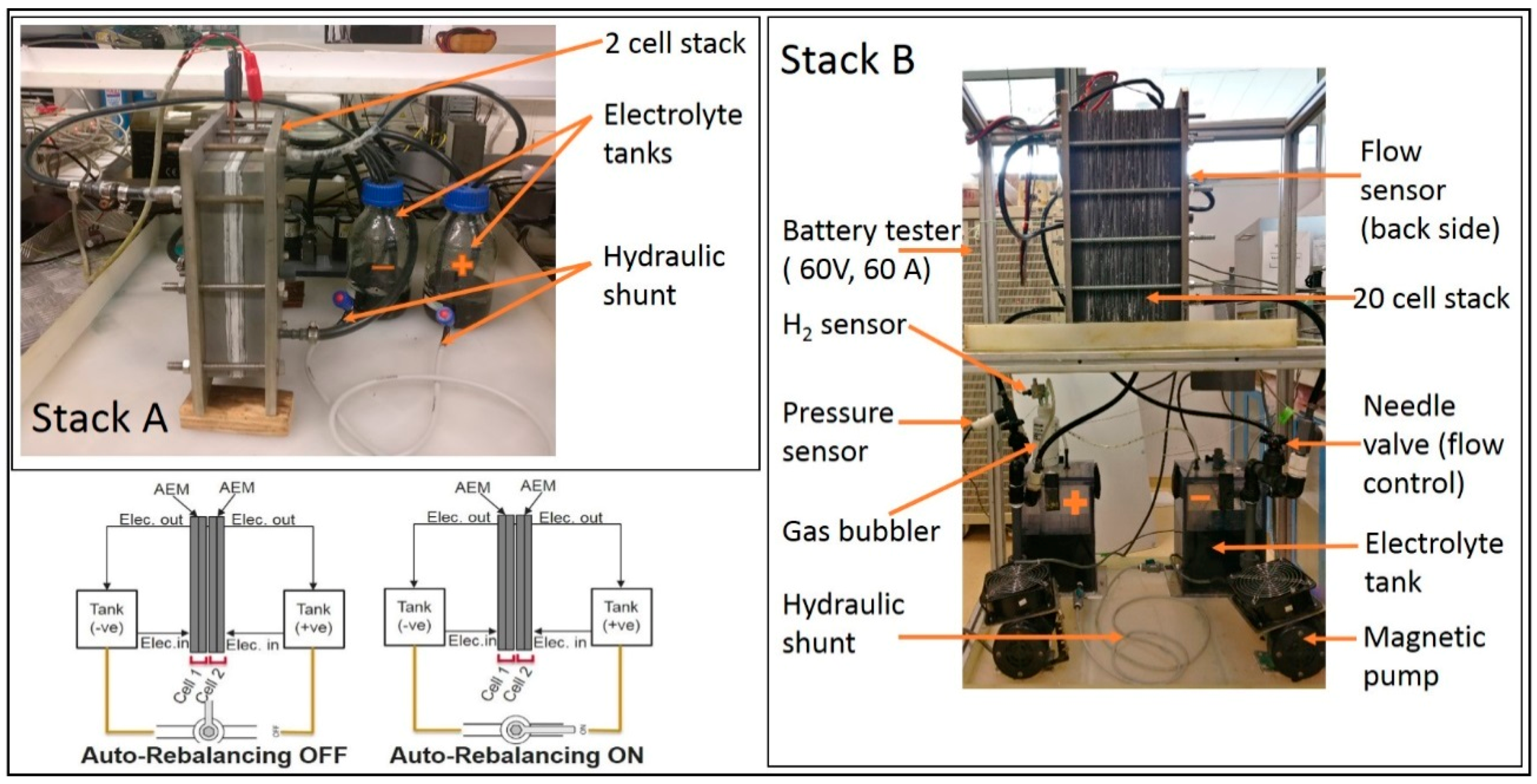
2.1. Hydraulic Shunt Test

The effectiveness of the use of hydraulic shunt for minimizing the capacity loss was tested on two different sizes of stacks, as shown in Figure 1.
Stack A and Stack B were assembled with 2-cell of 100 cm2 (10 cm × 10 cm) active area per cell and 20-cell of 625 cm2 (25 cm × 25 cm) active area per cell, respectively. Both stacks were assembled using partially fluorinated AEMs (FAP 450, Fumatech GmbH, Bietigheim, Germany), PAN-based carbon felt electrodes (SIGRACELL® GFD 4.6 EA from SGL Carbon, 86405 Meitingen, Germany, thermally treated at 600 °C for 5 h in air) and expanded graphite bipolar plates (SIGRACELL PV 15® from SGL Technic LLC, Valencia, California, USA). The electrolyte concentration was 1.6 M V3.5+ (i.e., 0.8 M V(III) and 0.8 M V(IV) ions) in 4.5 M total sulphate (GFE, Nuremberg, Germany). The electrolyte volume was 0.3 and 10 L per tank for Stack A and B, respectively. The electrolyte flow rate was maintained constant at 0.1 and 0.4 L·min−1 per cell for stack A and B, respectively. (The flow of positive and negative electrolytes were equal). For stack A, two diaphragm type DC pumps (KNF Neuberger Inc., Freiburg im Breisgau, Germany) were used and the electrolyte tanks were placed nearly at the same level of the stack. For Stack B, magnetic type ac pumps (IWAKI, Japan) were used and the electrolyte tanks were located underneath the stack similar to commercial systems. Paraffin oil (1 cm thick layer) was used on Stack A to prevent the aerial oxidation of V2+. In Stack B, air tight tanks filled with inert gas and a gas bubbler system was used for protecting the aerial oxidation of V2+.
The bottom part of each tank in both cases were fitted with a nozzle (ID = 2 mm) and needle valve, as shown in Figure 1. The two tanks were hydraulically shunted together using a flexible tube (Teflon) of 2 mm internal diameter. The length of the tube was 0.5 m in Stack A and 2 m in Stack B. Automatic level balancing between the tanks could be controlled by means of the valve. A schematic of the opening and closing of the auto-rebalancing in Stack A is shown in Figure 1.
The efficacy of the auto-rebalancing approach was evaluated by cell cycling (short-term and long-term).

2.2. Stack with a Combination of AEM and CEM

The 2-cell stack (Stack A, Figure 1) was assembled with a partially-fluorinated AEM (FAP 450, Fumatech GmbH, Bietigheim, Germany) and a per-fluorinated CEM (NafionTM 117, Du Pont, Wilmington, DE, USA). The auto-rebalancing was turned off i.e. the valve was closed. An equal flow rate of the electrolyte was maintained at each cell. Cell cycling was repeated over a range of current densities.

3. Results and Discussion

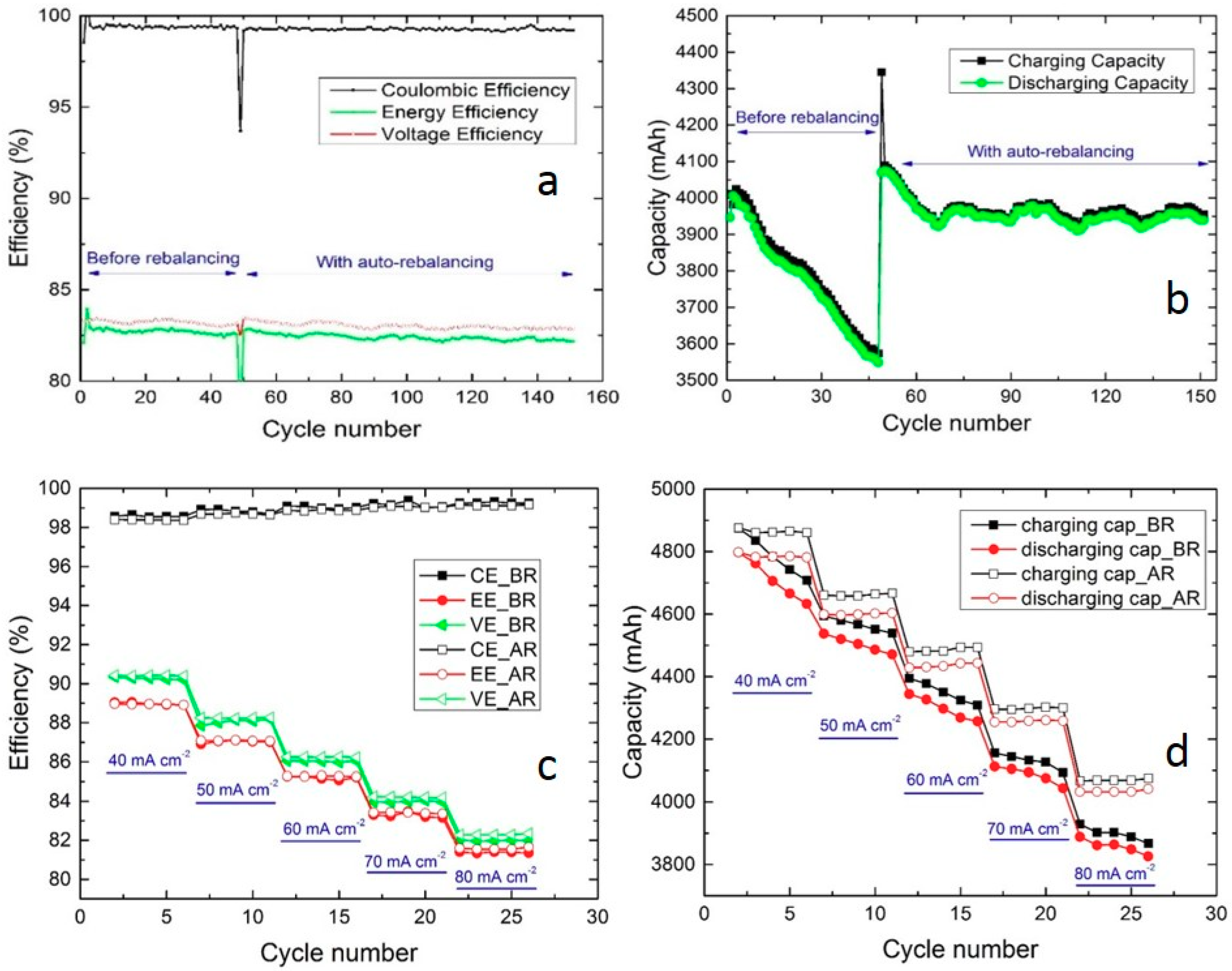
3.1. Hydraulic Shunt of Electrolyte Tanks

The Stack A was cycled at 80 mA cm−2 continuously for 50 cycles with the rebalancing deactivated. Afterwards, the valve was opened for auto-rebalancing and cycling was continued for another 100 cycles. The efficiencies and capacity, before and after the rebalancing, are compared in Figure 2a,b, respectively. The stack was further cycled at current densities of 40, 50, 60, 70 and 80 mA cm−2, with six cycles at each current density, to monitor the effect of variation in current density on capacity loss. The test was performed with and without auto-rebalancing. The efficiencies and capacities for both cases are compared in Figure 2c,d, respectively.
During long-term cycling, the coulombic efficiency (CE), energy efficiency (EE) and voltage efficiency (VE) remained similar before and after the valve was opened. However, the capacity decreased at ~0.2% (10 mAh) per cycle before rebalancing and stabilized after the auto-rebalancing. This provides evidence that the hydraulic shunt is effective in passively resolving the continuous capacity loss without detrimentally influencing the energy efficiency. Capacity loss was observed before rebalancing, mainly through differences in concentration of the sulfate and vanadium ions between the two tanks. This led to a continual narrowing of the state of charge (SOC) window over time. With an AEM, since the net volume transfer is to the negative tank, the positive electrolyte contains a smaller amount of total vanadium at a higher SOC than the negative electrolyte. Therefore, charging is limited by the positive electrolyte and discharging by the negative. The extent of volume imbalance dictates the width of the usable SOC range in each electrolyte. By routine overflow of the excess electrolyte or by continual volume balancing using a hydraulic shunt, the amount and hence SOC of vanadium remains balanced between the two tanks.
Compared to CEMs, AEMs have better ion selectivity for vanadium ions due to the Donnan effect, therefore partial or continuous remixing works more effectively for AEM than CEM cells, in retaining capacity. For a cell assembled with CEM (Nafion 117), Schafner et al. [21] observed that the overflow of the excess electrolyte effectively rebalanced the capacity, however, for extended period of cycling, a complete remixing will be needed for complete balancing of concentration and oxidation states of vanadium and sulfate ions.
The CE, EE and VE during short-term cycling also remained unchanged for both conditions at all current densities studied (Figure 2c). However, capacity fade was found to be almost independent of current density, although it decreased massively after activating the hydraulic shunt (Figure 2d). As expected, a drop in capacity with increasing current density was observed due to cycling between fixed voltage limits.
This simple concept is advised to flow battery researchers to implement while testing lab scale size cells operated with a small volume of electrolyte, to eliminate the effects arising from electrolyte crossover (such as small decrement in EE, VE, capacity (Ah) and energy (Wh) during cycling). In our earlier work [19,26], the EE was reduced by 2.3% in 45 cycles. Such fluctuation in EE, VE and capacity can mislead the information gained while conducting various research related to material development, design etc. In addition, the continual volume increment in the negative tanks due to the use of AEM membranes results in gradual concentration increment of vanadium ions in the positive tank. This can increase the risk of precipitation of the V2O5 in the positive tank and stack. Therefore, a routine or continuous rebalancing is important.
Figure 3 shows the efficiencies and capacity plot of an in-house developed 1 kW size stack tested over 250 cycles with auto-rebalancing of electrolyte.
In a larger system, the hydraulic shunt approach also worked efficiently as a stable CE, EE, VE, charging capacity and discharging capacity was observed. A negligible capacity decay was observed during 260 cycles. The length and diameter of the tube can be further optimized. A too short tube (or larger diameter) may lead to a quick mixing of electrolyte between two tanks, decreasing EE and CE, whilst a too long tube (or too small diameter) would result in discontinuous mixing. A tube length to diameter ratio of more than 10 was proposed in the patent literature [23]. During testing in a 1 kW stack, it was also realized that the air bubbles must be avoided from entering the tube, otherwise that would stop the auto-rebalancing.
Hence, our results show that hydraulic shunt approach can be directly implemented in commercial systems and solve the problem of frequently requiring full or partial remixing of electrolyte.

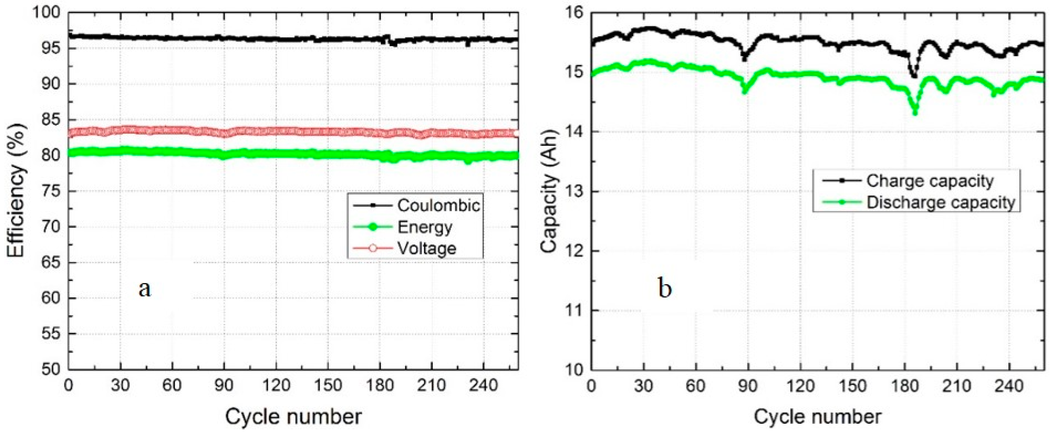
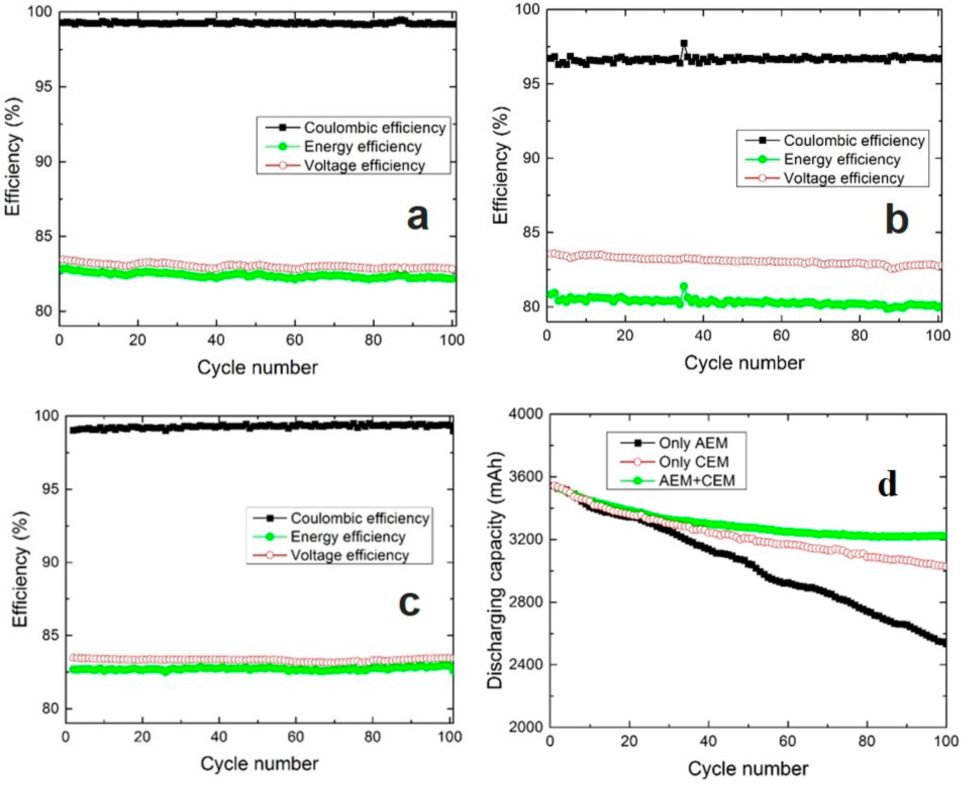
3.2. Use of a Combination of AEM and CEM

With a CEM, the net transfer of electrolyte occurs from negative to positive electrolytes, whereas the opposite is true for an AEM. Therefore, it is proposed that a combination of both membranes should result in a lower imbalance of electrolyte and hence lower capacity loss. However, no experimental proof is available to date.
Figure 4 shows the performance of a 2-cell stack assembled with (a) only AEM, (b) only CEM and (c) AEM + CEM. Figure 4d shows the comparison of capacity decay for all three combinations.
The CE of the stack assembled with Nafion membrane (Figure 4b) is slightly inferior to that of FAP 450 (Figure 4a). This well-known behavior is due to a higher vanadium transport through the Nafion membrane. AEMs are more attractive than CEMs due to their fundamental property of restricting the crossover of cationic active species by Donnan effects [20]. In an AEM, the positively charged fixed ionic groups repel positively charged vanadium ions and hence reduce the crossover of vanadium ions as compared to CEMs. However, AEMs usually suffer from poor conductivity, stability and selectivity [27]. Therefore, the VE of a cell employing a Nafion CEM (Figure 4b) is higher as the membrane has a lower resistivity. The performance of a cell assembled with a combination of AEM and CEM showed a stable and similar performance to that of cells assembled with identical membranes. The short-term cycling test, at different current densities of a cell assembled with combination of AEM/CEM also showed stable performance (Figure S1 in Supplementary Materials). Hence, this study demonstrates the viability of using a combination of AEM and CEM for the first time.
The capacity loss was higher for the cell assembled with only AEM (FAP450) compared to the cell assembled with only CEM (Nafion 117). The results are in close agreement with the literature [7]. As observed from Figure 4d, the capacity loss reduced with a combination of AEM and CEM. This further proves that a combination of AEM and CEM can be used in a stack to reduce the net electrolyte flux. However, in a multi-cell stack, the number of AEM and CEM have to be optimized for achieving stable capacity over prolonged operation. The resistivity and the rate of crossover should match to obtain a best performance.
The auto-rebalancing approach was also tested on a stack assembled with a combination of AEM and CEM. With continuous rebalancing of electrolyte through a hydraulic shunt, the capacity remained stable over 125 cycles (Figure S2 in Supplementary Materials).
Both methods (auto-rebalancing and use of AEM and CEM in a stack) are passive and therefore easier in practice than alternatives involving SOC monitoring and pumping [28], and certainly easier than trying to find new membrane chemistries.

4. Conclusions

Two simple approaches were proposed in order to minimize the electrolyte imbalance and reversible capacity loss in VRFB. The auto-rebalancing of electrolyte was accomplished by means of a hydraulic shunt between two tanks. A narrow and long tube was connected at the bottom of the two tanks in order to continuously balance the volumes. This approach was found to be very effective in both 100 cm2 size stack and 1 kW size stack. The capacity fade during 100 cm2 size stack testing was ~0.2% (10 mAh) per cycle, which after auto-rebalancing remained stable for 100 cycles with no drop in stack efficiency. Similarly, a 1 kW stack tested with a small volume of electrolyte, to reduce the testing time, the auto-rebalancing approach resulted in stable capacity and efficiencies for 260 cycles. This method is simple to adopt in both laboratory and commercial size cells/stacks.
The use of a combination of AEM and CEM is similarly effective with respect to capacity retention. As compared to stack assembled with solely AEM or CEM, the stack assembled with a combination of AEM and CEM resulted in lower capacity loss.

Supplementary Materials

The following are available online at: https://www.mdpi.com/2313-0105/4/4/48/s1, Figure S1: CE, EE and VEs at different current density of a 2-cell stack assembled with a combination of AEM and CEM. Figure S2: Charging and discharging capacity over 125 cycles after auto-rebalancing of a 2-cell stack assembled with a combination of AEM and CEM.

Author Contributions

Conceptualization, A.B. and A.W.; methodology, A.B., P.C.G. and N.W.; validation, A.W. and R.S.; writing: original draft preparation, A.B. and P.C.G., editing, G.G.S. and H.H.H., supervision, H.H.H.

Funding

This research was funded by SGL Carbon GmbH, Germany and Nanyang Technological University, Singapore.

Conflicts of Interest

The authors declare no conflict of interest. The funders had no role in the design of the study; in the collection, analyses, or interpretation of data; in the writing of the manuscript, and in the decision to publish the results.

Abbreviations

AcronymDefinition
VRFBVanadium redox flow battery
CEMCation exchange membrane
AEMAnion exchange membrane
PANPolyacrylonitrile
CECoulombic efficiency
EEEnergy efficiency
VEVoltage efficiency
SOCState of charge

References

  1. Poullikkas, A. A comparative overview of large-scale battery systems for electricity storage. Renew. Sustain. Energy Rev. 2013, 27, 778–788. [Google Scholar] [CrossRef]
  2. Alotto, P.; Guarnieri, M.; Moro, F. Redox flow batteries for the storage of renewable energy: A review. Renew. Sustain. Energy Rev. 2014, 29, 325–335. [Google Scholar] [CrossRef]
  3. Parasuraman, A.; Lim, T.M.; Menictas, C.; Skyllas-Kazacos, M. Review of material research and development for vanadium redox flow battery applications. Electrochim. Acta 2013, 101, 27–40. [Google Scholar] [CrossRef]
  4. Cao, L.; Kronander, A.; Tang, A.; Wang, D.-W.; Skyllas-Kazacos, M. Membrane Permeability Rates of Vanadium Ions and Their Effects on Temperature Variation in Vanadium Redox Batteries. Energies 2016, 9, 1058. [Google Scholar] [CrossRef]
  5. Sun, C.; Chen, J.; Zhang, H.; Han, X.; Luo, Q. Investigations on transfer of water and vanadium ions across Nafion membrane in an operating vanadium redox flow battery. J. Power Sources 2010, 195, 890–897. [Google Scholar] [CrossRef]
  6. Luo, Q.; Li, L.; Nie, Z.; Wang, W.; Wei, X.; Li, B.; Chen, B.; Yang, Z. In-situ investigation of vanadium ion transport in redox flow battery. J. Power Sources 2012, 218, 15–20. [Google Scholar] [CrossRef]
  7. Mohammadi, T.; Chieng, S.; Kazacos, M.S. Water transport study across commercial ion exchange membranes in the vanadium redox flow battery. J. Membr. Sci. 1997, 133, 151–159. [Google Scholar] [CrossRef]
  8. Luo, Q.; Li, L.; Wang, W.; Nie, Z.; Wei, X.; Li, B.; Chen, B.; Yang, Z.; Sprenkle, V. Capacity decay and remediation of Nafion-based all-vanadium redox flow batteries. ChemSusChem 2013, 6, 268–274. [Google Scholar] [CrossRef] [PubMed]
  9. Chieng, S.C. Membrane Processes and Membrane Modification for Redox Flow Battery Applications. Ph.D. Thesis, University of New South Wales, Sydney, Australia, 1993. [Google Scholar]
  10. Yan, Y.; Gu, S.; Gong, K. Multiple-Membrane Multiple-Electrolyte Redox Flow Battery Design. U.S. Patent 9,640,826, 14 June 2013. [Google Scholar]
  11. Mohammadi, T.; Kazacos, M.S. Modification of anion-exchange membranes for vanadium redox flow battery applications. J. Power Sources 1996, 63, 179–186. [Google Scholar] [CrossRef]
  12. Sukkar, T.; Skyllas-Kazacos, M. Modification of membranes using polyelectrolytes to improve water transfer properties in the vanadium redox battery. J. Membr. Sci. 2003, 222, 249–264. [Google Scholar] [CrossRef]
  13. Qiu, J.; Zhang, J.; Chen, J.; Peng, J.; Xu, L.; Zhai, M.; Li, J.; Wei, G. Amphoteric ion exchange membrane synthesized by radiation-induced graft copolymerization of styrene and dimethylaminoethyl methacrylate into PVDF film for vanadium redox flow battery applications. J. Membr. Sci. 2009, 334, 9–15. [Google Scholar] [CrossRef]
  14. Oldenburg, F.J.; Schmidt, T.J.; Gubler, L. Tackling capacity fading in vanadium flow batteries with amphoteric membranes. J. Power Sources 2017, 368, 68–72. [Google Scholar] [CrossRef]
  15. Hu, G.; Wang, Y.; Ma, J.; Qiu, J.; Peng, J.; Li, J.; Zhai, M. A novel amphoteric ion exchange membrane synthesized by radiation-induced grafting α-methylstyrene and N,N-dimethylaminoethyl methacrylate for vanadium redox flow battery application. J. Membr. Sci. 2012, 407–408, 184–192. [Google Scholar] [CrossRef]
  16. Franken, T. Bipolar membrane technology and its applications. Membr. Technol. 2000, 2000, 8–11. [Google Scholar] [CrossRef]
  17. Nibel, O.; Schmidt, T.J.; Gubler, L. Bifunctional ion-conducting polymer electrolyte for the vanadium redox flow battery with high selectivity. J. Electrochem. Soc. 2016, 163, A2570. [Google Scholar] [CrossRef]
  18. Sekiguchi, S.; Furusato, K.; Miyabayashi, M.; Satou, K.; Tanimoto, T.; Naitou, S. Redox Flow Battery. U.S. Patent 6,764,789, 27 September 1999. [Google Scholar]
  19. Wang, K.; Liu, L.; Xi, J.; Wu, Z.; Qiu, X. Reduction of capacity decay in vanadium flow batteries by an electrolyte-reflow method. J. Power Sources 2017, 338, 17–25. [Google Scholar] [CrossRef]
  20. Skyllas-Kazacos, M.; Menictas, C. The vanadium redox battery for emergency back-up applications. In Proceedings of the Telecommunications Energy Conference, Melbourne, Australia, 2–5 April 1997; pp. 463–471. [Google Scholar] [CrossRef]
  21. Schafner, K.; Becker, M.; Turek, T. Capacity balancing for vanadium redox flow batteries through electrolyte overflow. J. Appl. Electrochem. 2018, 48, 639–649. [Google Scholar] [CrossRef]
  22. Agar, E.; Benjamin, A.; Dennison, C.R.; Chen, D.; Hickner, M.A.; Kumbur, E.C. Reducing capacity fade in vanadium redox flow batteries by altering charging and discharging currents. J. Power Sources 2014, 246, 767–774. [Google Scholar] [CrossRef]
  23. Pellegri, A.; Broman, B.M. Redox Flow Battery System and Cell Stack. U.S. Patent 6475661B1, 28 January 1998. [Google Scholar]
  24. Mou, L.; Huang, M.; Andy, C.; Mclennan, H.M.A. Redox Flow Battery and Method for Enabling Battery to Operate Continuously for Long Time. Patent CN102055000, 14 December 2009. [Google Scholar]
  25. Genders, J.D.; Hennessy, T.D.J.; Symons, P.G. Vanadium Redox Battery cell Stack. WO Patent 2,007,040,545, 23 September 2005. [Google Scholar]
  26. Bhattarai, A.; Wai, N.; Schweiss, R.; Whitehead, A.; Lim, T.M.; Hng, H.H. Advanced porous electrodes with flow channels for vanadium redox flow battery. J. Power Sources 2017, 341, 83–90. [Google Scholar] [CrossRef]
  27. Cha, M.S.; Jeong, H.Y.; Shin, H.Y.; Hong, S.H.; Kim, T.-H.; Oh, S.-G.; Lee, J.Y.; Hong, Y.T. Crosslinked anion exchange membranes with primary diamine-based crosslinkers for vanadium redox flow battery application. J. Power Sources 2017, 363, 78–86. [Google Scholar] [CrossRef]
  28. Corcuera, S.; Skyllas-Kazacos, M. State-of-charge monitoring and electrolyte rebalancing methods for the vanadium redox flow battery. Eur. Chem. Bull. 2012, 1, 511–519. [Google Scholar] [CrossRef]
Figure 1. Test setups used for hydraulic shunt measurement.
Batteries 04 00048 g001
Figure 2. Comparison of efficiencies (a) and capacity (b) during cycling at 80 mA cm−2, and efficiencies (c) and capacity (d) during cycling at different current densities, before and after the auto-rebalancing of Stack A. (BR = before rebalancing, AR = after rebalancing).
Batteries 04 00048 g002
Figure 3. Performance of an in-house developed 1 kW stack tested with auto-rebalancing of electrolyte (a) coulombic efficiency, energy efficiency and voltage efficiency and (b) charge and discharge capacity (in Ah).
Batteries 04 00048 g003
Figure 4. Coulombic, energy and voltage efficiency of a 2-cell stack with, only anion exchange membrane (AEM+AEM) combination (a), only cation exchange membrane (CEM + CEM) combination (b), an anion and a cation exchange membrane (AEM + CEM) combination (c) and capacity decay during cycling of cells with all three membrane combinations (d).
Batteries 04 00048 g004

