Article

Electron Backscatter Diffraction Studies on the Formation of Superlattice Metal Hydride Alloys

1
Department of Chemical Engineering and Materials Science, Wayne State University, Detroit, MI 48202, USA
2
BASF/Battery Materials—Ovonic, 2983 Waterview Drive, Rochester Hills, MI 48309, USA
3
School of Materials and Metallurgy, Inner Mongolia University of Science and Technology, Baotou 014010, Inner Mongolia, China
4
Department of Chemistry, Wayne State University, Detroit, MI 48202, USA
*
Author to whom correspondence should be addressed.
Batteries 2017, 3(4), 40; https://doi.org/10.3390/batteries3040040
Submission received: 2 October 2017 / Revised: 4 December 2017 / Accepted: 5 December 2017 / Published: 13 December 2017
(This article belongs to the Special Issue Nickel Metal Hydride Batteries 2017)

Abstract

:
Microstructures of a series of La-Mg-Ni-based superlattice metal hydride alloys produced by a novel method of interaction of a LaNi5 alloy and Mg vapor were studied using a combination of X-ray energy dispersive spectroscopy and electron backscatter diffraction. The conversion rate of LaNi5 increased from 86.8% into 98.2%, and the A2B7 phase abundance increased from 42.5 to 45.8 wt % and reduced to 39.2 wt % with the increase in process time from four to 32 h. During the first stage of reaction, Mg formed discrete grains with the same orientation, which was closely related to the orientation of the host LaNi5 alloy. Mg then diffused through the ab-phase of LaNi5 and formed the AB2, AB3, and A2B7 phases. Diffusion of Mg stalled at the grain boundary of the host LaNi5 alloy. Good alignments in the c-axis between the newly formed superlattice phases and LaNi5 were observed. The density of high-angle grain boundary decreased with the increase in process time and was an indication of lattice cracking.

Graphical Abstract

1. Introduction

Rare earth (RE)/Mg-based superlattice metal hydride (MH) alloys are employed extensively in the consumer nickel/metal hydride (Ni/MH) batteries because of the following improvements over the conventional AB5 MH alloys: higher hydrogen storage capacities, better high-rate dischargeability (HRD), superior low-temperature and charge-retention performances, and improved cycle stability [1,2,3,4,5,6,7,8]. Out of the six available superlattice phases (three hexagonal and three rhombohedral), Ce2Ni7 was found to be the most desirable phase considering general battery performance [9], and the A2B7 stoichiometry shows the best HRD, charge retention, and cycle life [10]. Although the superlattice MH alloys are very attractive to battery engineers, their fabrication is difficult because of the high vapor pressure of Mg [11]—an indispensable ingredient to maximize the capacity and stabilize the structure [12,13]. In the conventional melt-and-cast method, Mg was added as a late addition in the form of MgNi2 [14]. Extra Mg needs to be added to compensate for the loss to vapor, which is a difficult factor to control precisely. A new method of making the Mg-containing superlattice MH alloys [15] was proposed using a gaseous-state Mg-diffusion into the AB5 MH alloys, which can be easily produced by vacuum induction melting with a furnace size as large as one ton [16]. Early electron microscope studies indicated the feasibility of transporting Mg into the La0.8Ni3 alloy and forming the Mg-containing superlattice phases, but the constituent phases have not yet been confirmed [15].
Electron backscatter diffraction (EBSD) is a microstructural-crystallographic technique that allows the user to examine the crystallographic orientations of constituent phases in very localized areas (one square micron or less) of a polycrystalline material in a scanning electron microscope (SEM). Capability of EBSD can be further enhanced by including the chemical composition information gathered by X-ray energy dispersive spectroscopy (EDS) [17]. In the past, we employed EBSD in the studies of a Zr7Ni10 [18], a C14-based AB2 [19], and a C14/body-centered-cubic MH alloys [20]. In the last two cases, EBSD was used to confirm the cleanliness of the grain boundary from the strong alignment of crystallographic orientations of neighboring phases. In the current study, EBSD was used to identify the new phases formed by the Mg-diffusion into the LaNi5 alloy and study the nature of grain boundary and alignment of crystallographic orientations of neighboring phases.

2. Experimental Setup

The LaNi5 alloy was synthesized by induction melting La and Ni (both with purity higher than 99.5%) under an argon atmosphere. Solidification of the LaNi5 alloy was operated by a rapid quenching equipment to ensure the slice thickness to be between 0.2 to 0.4 mm. The Mg-absorption alloying process was operated in a sealed internal isolation stainless-steel retort. Slices of Mg and LaNi5 were placed into each side of the retort in a weight ratio of Mg:LaNi5 = 1:30 and separated by foraminiferous septa. The retort was placed in an annealing furnace under an inert atmosphere (argon). Annealing (reaction) temperature was increased from the ambient temperature to 1273 K with a heating rate of 10 K·min−1. Afterward, the vessel was cooled to room temperature in the furnace.
4-h, 8-h, 16-h, and 32-h annealed alloy samples were mounted in resin holders. The samples were polished using metallographic silicon carbide sandpapers in the sequence of 400-, 800- and, finally, 1200-grit (Buehler, Lake Bluff, IL, USA), and they were then finely polished with Buehler MicroPolish II Suspension 1-µm alumina suspension and PACE Technologies SIAMAT2 0.02-µm colloidal silica (PACE Technologies, Tucson, AZ, USA) to obtain a mirror finish. The prepared samples were kept in a sealed tank with high vacuum and low O2 and moisture content to avoid surface oxidization and physical and chemical absorptions.
To investigate the phase distribution, samples were studied by a JEOL JSM-7600 field emission SEM (JEOL USA, Inc., Peabody, MA, USA) equipped with an EDAX Pegasus Apex 2 Integrated EDS and EBSD System (EDAX Inc., Mahwah, NJ, USA). The EBSD data was collected and analyzed with TSL OIM data Collection 7 and TSL OIM Analysis 7 program (EDAX Inc., Mahwah, NJ, USA)., respectively. - All the measured points have confidence indices greater than 0.6, which corresponds to an accuracy higher than 95%. Fit parameter is the averaged angular difference between the detected and recalculated bands. In this case, the fit parameter is less than 0.8, showing a high degree of matching.

3. Results and Discussion

3.1. Phase Identification

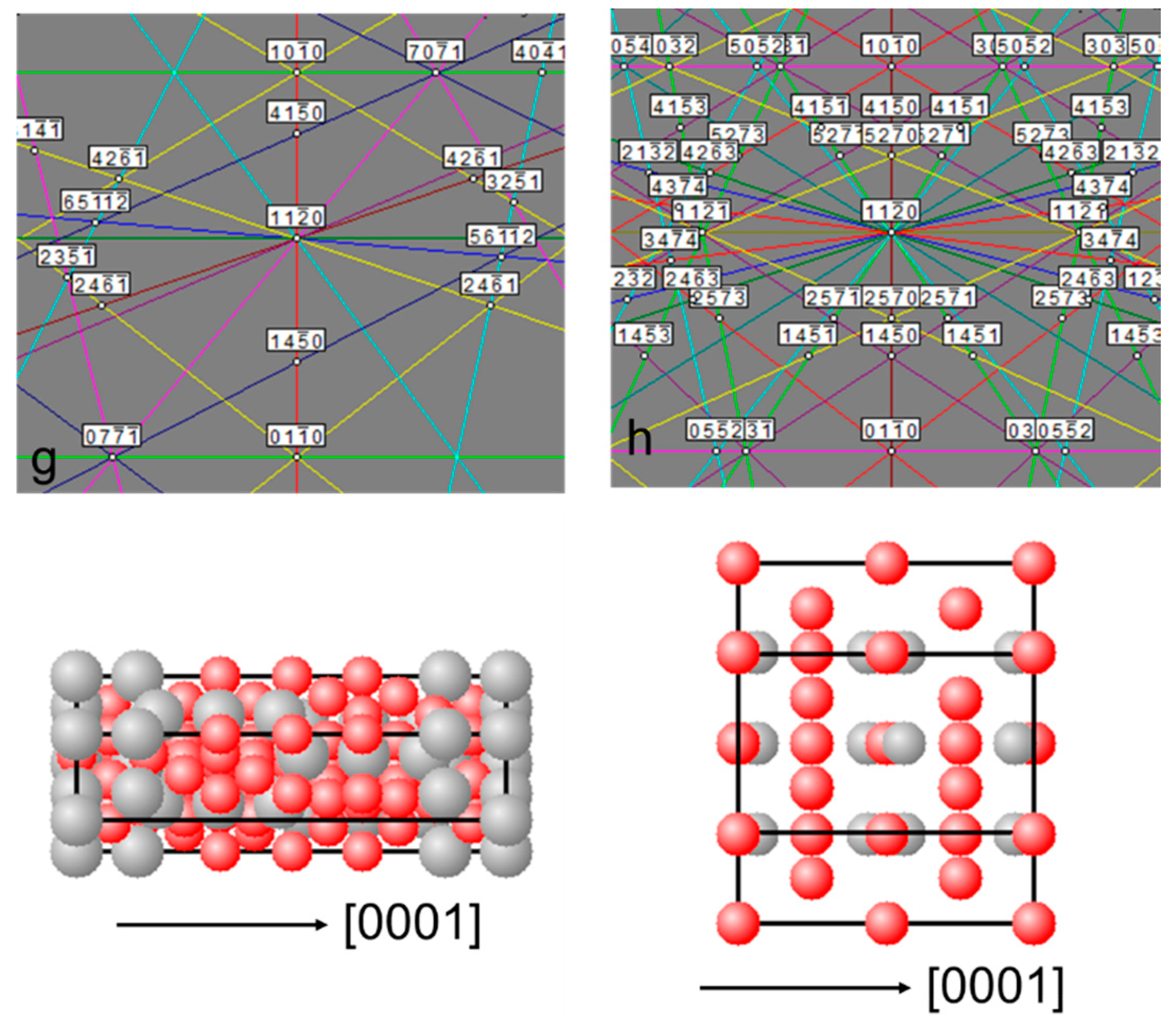
As stated in the Introduction, the La-Mg-Ni-type alloys were based on the La-Ni binary intermetallic alloys. The presence of Mg destabilizes the hydride, making it suitable for room-temperature battery applications [13]. Phases commonly reported in the La-Mg-Ni superlattice alloys are (La,Mg)Ni5, (La,Mg)5Ni19, (La,Mg)2Ni7, (La,Mg)Ni3, and (La,Mg)Ni2. [21]. Basic subunits for these phases are the AB5 and A2B4 slabs, which alternatively stack along the c-axis in different patterns to form the structures [21,22]. Six types of the La-Mg-Ni superlattice phases are Pr5Co19 (PDF: 04-004-1477), Nd5Co19 (PDF: 04-004-1478), Ce2Ni7 (PDF: 04-007-1092), Pr2Ni7 (PDF: 01-081-8491), CeNi3 (PDF: 04-007-1090), and PuNi3 (PDF: 04-007-1091), and their structures are either hexagonal or rhombohedral and are generally difficult to distinguish in the X-ray diffraction patterns [21,22,23,24,25]. Furthermore, the AB5 (PDF: 00-055-0277) and AB2 (PDF: 04-001-2137) phases are also hexagonal, which adds to the difficulty in identifying the phases. EBSD provides a powerful approach to study the lattice structures of individual phases and their alignments in certain orientations in the multi-phase La-Mg-Ni superlattice alloys. Figure 1 shows the crystal structures and computer-generated EBSD diffraction patterns of the (11 2 0) planes of LaNi5, Pr5Co19, Nd5Co19, Ce2Ni7, Pr7Ni2, CeNi3, PrNi3, and NbCr2 (hexagonal), which are used as the base patterns in this study. Lattice parameters of the seven types of structures are different and, therefore, their EBSD patterns are different, especially away from the (0001) plane.
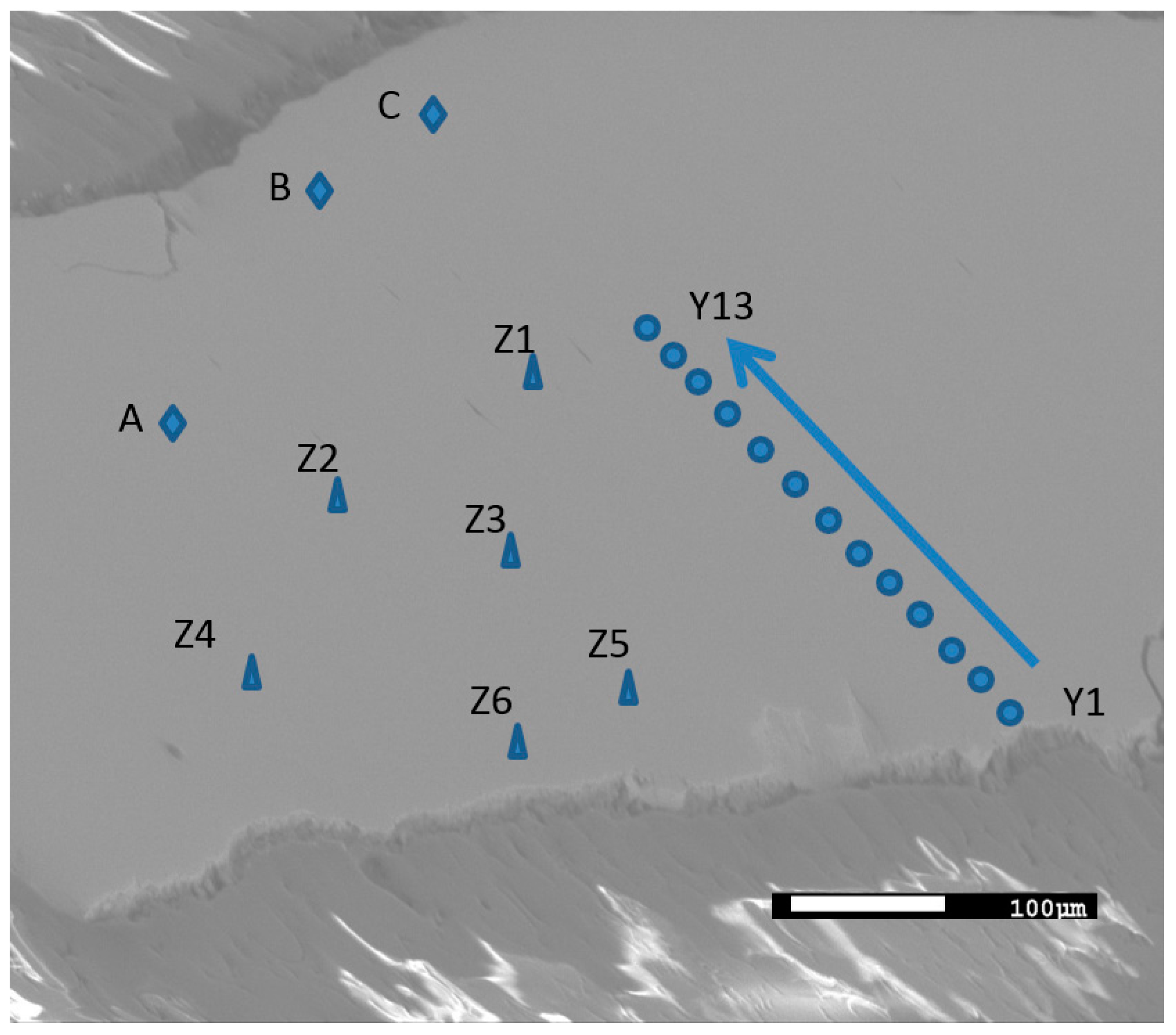
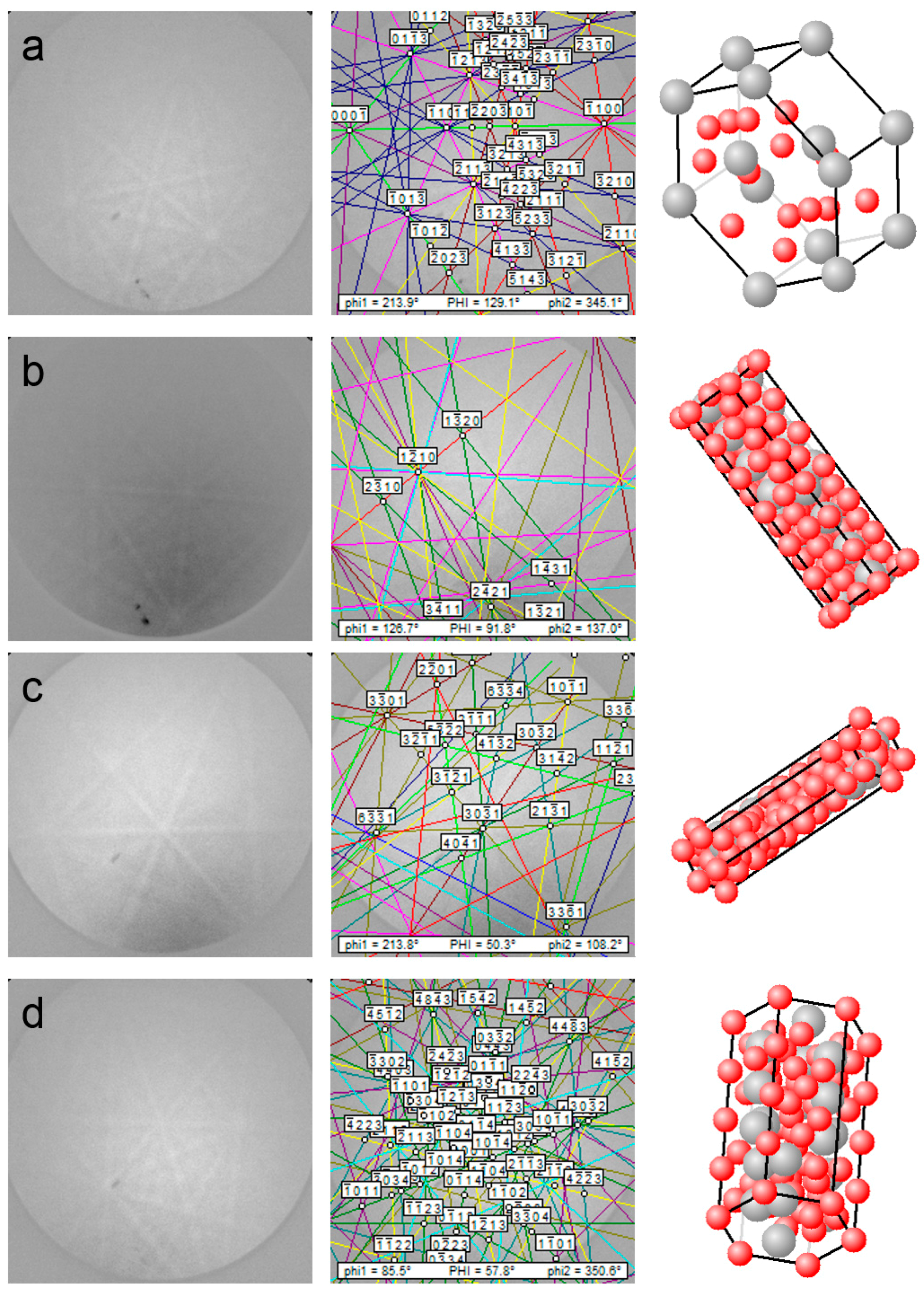
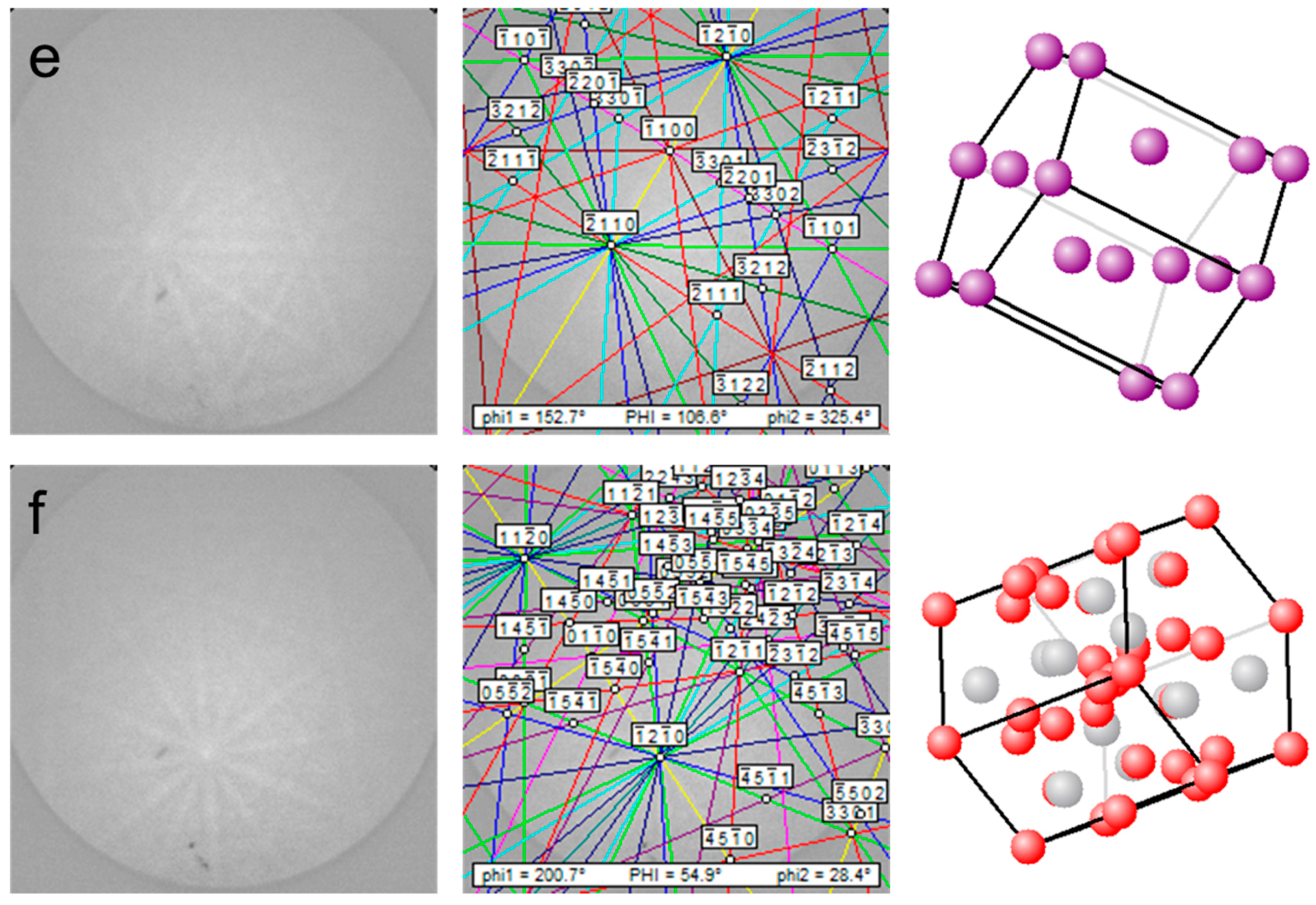
SEM-backscattered electron image (BEI) of the 8-h annealed sample is shown in Figure 2, and several spots were studied in detail (spots Z1 to Z6, A to C, and Y1 to Y13). For spots Z1 to Z6, their original EBSD patterns, fitted patterns, and simulations of grain orientation are shown in Figure 3. Other than the base structure (LaNi5, spot Z1), both the A2B7 (spots Z2 and Z3) and AB3 (spot Z4) superlattice structures, Mg metal (spot Z5), and AB2 (spot Z6) phases are found as the new phases. All the patterns are blurry, which can be caused by multiple factors: besides the issues of imperfection in the sample polish and limited camera resolution, strains in the alloy can also influence the band contrasts.
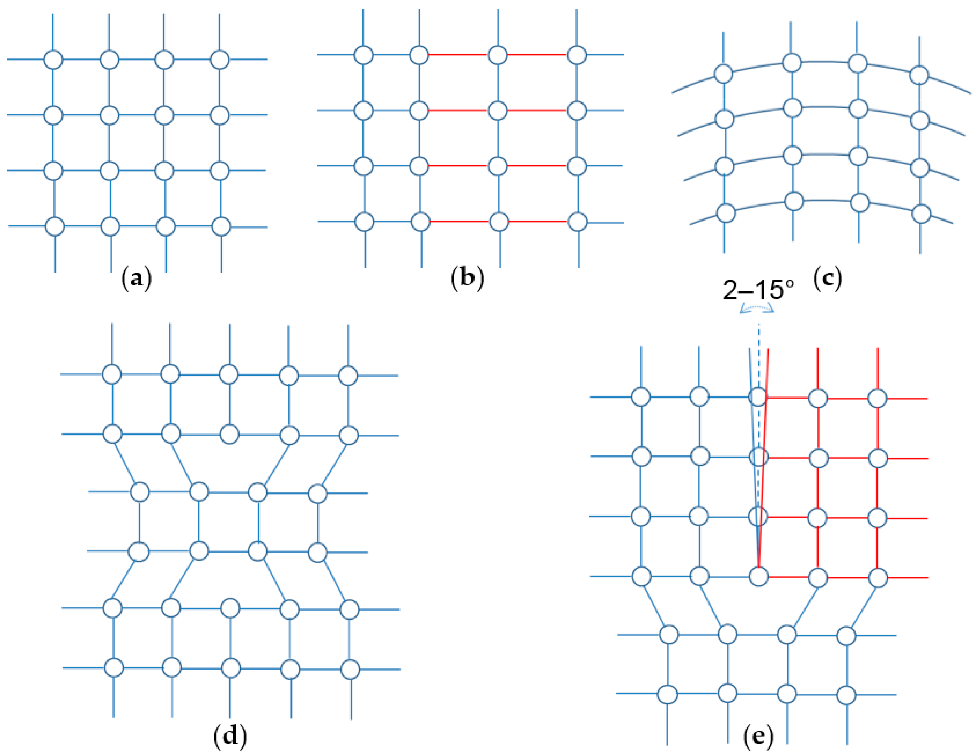
Elastic and plastic strains have been reported to cause other changes in the EBSD patterns [26]. Figure 4 shows the EBSD patterns from spots A to C, and they are identified as LiNi5, Ce2Ni7, and Pr2Ni7, respectively. Except for the blurriness, a new band (B2 in Figure 4b) and bands with a slight rotation (A1 in Figure 4a), a shift (A2 in Figure 4a), a narrower diffraction width (B1 in Figure 4b), and a wider diffraction width (C1 in Figure 4c) are observed. Figure 5 shows the schematic diagrams of a few lattice distortions that may cause the changes in the EBSD patterns. Elastic strains distort the crystal lattice. Winkelmann reported that if the elastic strains uniformly dilate the lattice, changes in the EBSD patterns only occur in bandwidth [27]. If other lattice distortions exist, such as partially-lengthened bonds in the lattice (Figure 5b), shifts in some zone axes in the EBSD patterns can occur [26]. Keller et al. [28] reported that a “bent” crystal, as shown in Figure 5c, leads to a slight degradation in pattern quality and a minor band rotation. Since the planes within the diffraction volume are no longer exactly parallel to each other, blurring of diffraction bands and band rotation occur and are caused by the slight changes in Bragg angles. Plastic strains lead to dislocations in the crystal lattice, and Figure 5d,e demonstrate two types of dislocations. The region in the material with a high dislocation density with a net Burgers vector of zero is considered to have statistically stored dislocations (SSD) (Figure 5d). The resulting pattern in the area containing SSDs is degraded because of the local perturbations of diffracting lattice planes that result in incoherent scattering [26]. The area with dislocations with a net-nonzero Burgers vector have geometrically-necessary dislocations (GND). Arrays of GNDs can form subgrain boundaries (Figure 5e) and degrade the EBSD pattern quality by the superposition of patterns from neighboring subgrains with a small rotation in between [26,28]. The influences of misorientation on the quality of EBSD pattern are further elaborated in Supplemental 1 with a SEM micrograph showing three locations with small misorientations (Figure S1) and the corresponding EBSD patterns (Figure S2).
In this study, the La-Mg-Ni alloys were prepared by a solid-state method with Mg diffusing into the LaNi5 alloy. Therefore, both elastic and plastic strains were formed during the Mg-diffusion process and have strong influences on the EBDS pattern clarity. During the Mg-diffusion process, defects in the raw LaNi5 alloys were generated while new phases were formed. Physical and chemical properties of the La-Mg-Ni alloys prepared by this method are affected by the distribution of defects, and compositions and abundances of constituent phases. Therefore, investigating the alloys’ microstructures by the EBSD technique becomes important.

3.2. Phase Distribution

3.2.1. Element Distribution

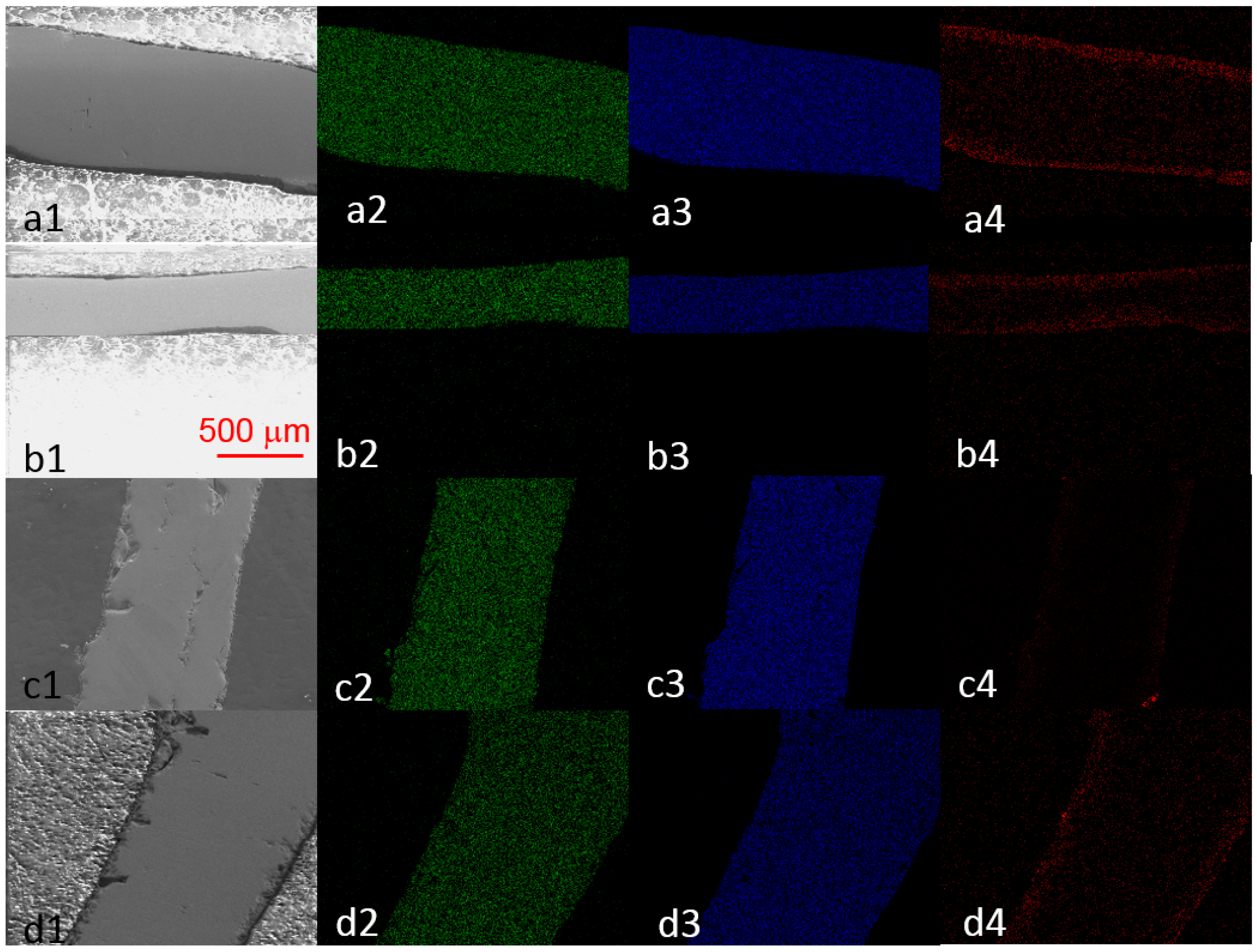
To fully characterize the alloys’ microstructures, EDS elemental mappings were conducted on all four alloys (4 h-, 8 h-, 16 h-, and 32-h annealed samples), and the results are shown in Figure 6. While La and Ni distribute uniformly in all alloys, Mg shows a high concentration at the edges of all alloys. The EDS results of spots Y1 to Y13 in the SEM micrograph of the 8-h annealed sample (Figure 2) are listed in Table 1, which demonstrate the uneven distribution of Mg from the edge to center of alloy. Penetration of Mg into the 8-h annealed sample is about 100 microns. The value of Ni/(La + Mg) varies from 1.49 to 5.32, and the varying trend indicates that the phase changes along the longitudinal section (from one surface to another) of alloy. However, it must be stated that EDS is a semi-quantitative analysis method, so other technologies have to be combined with EDS to validate the phase distribution.

3.2.2. Phase Distribution

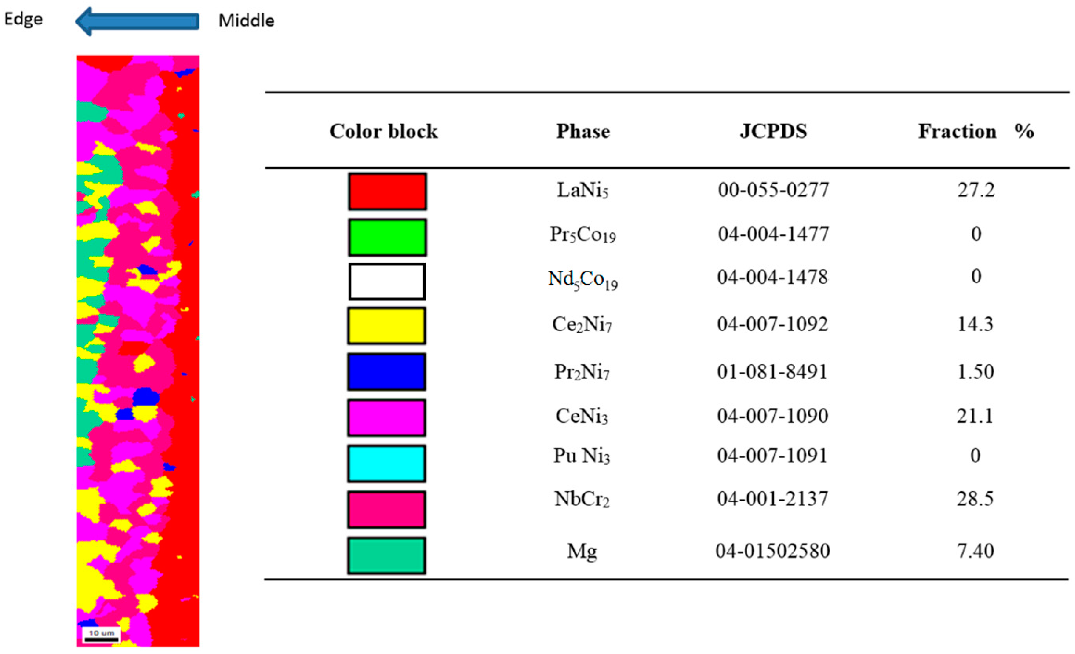
As an example, phase identification mapping by EBSD of the 16-h annealed sample is shown in Figure 7. Six phases, including LaNi5, Ce2Ni7, Pr2Ni7, CeNi3, NbCr2 (hexagonal), and Mg, can be identified. In the investigated area of the 16-h annealed sample, the Pr5Co19, Nd5Co19, and PuNi3 structures are not found. A gradient of phase abundance can be observed for most phases. LaNi5, the unreacted material, is concentrated in the center. While the diffuse-in Mg is concentrated at the edge, Ce2Ni7, one of the important target products [9], is also concentrated at the edge. Existence of pure Mg phase is validated in Supplement 2 with SEM micrographs (Figure S3) and EDS results showing high-Mg contents (Table S1). Pr2Ni7, another one of the target products, is located mainly between the LaNi5 and Mg phases. Abundances of the six phases in the investigated area are summarized in the table included in Figure 7. The LaNi5 abundance is 27.2%, and the combined abundance of Ce2Ni7 and Pr2Ni7 is 15.8%. The CeNi3 and NbCr2 phases are products from the overreaction of Ce2Ni7 and Pr2Ni7 with Mg. Future work will focus on increasing the Ce2Ni7 and Pr2Ni7 phase abundances.

3.2.3. LaNi5 and Mg Grain Distributions and Orientations

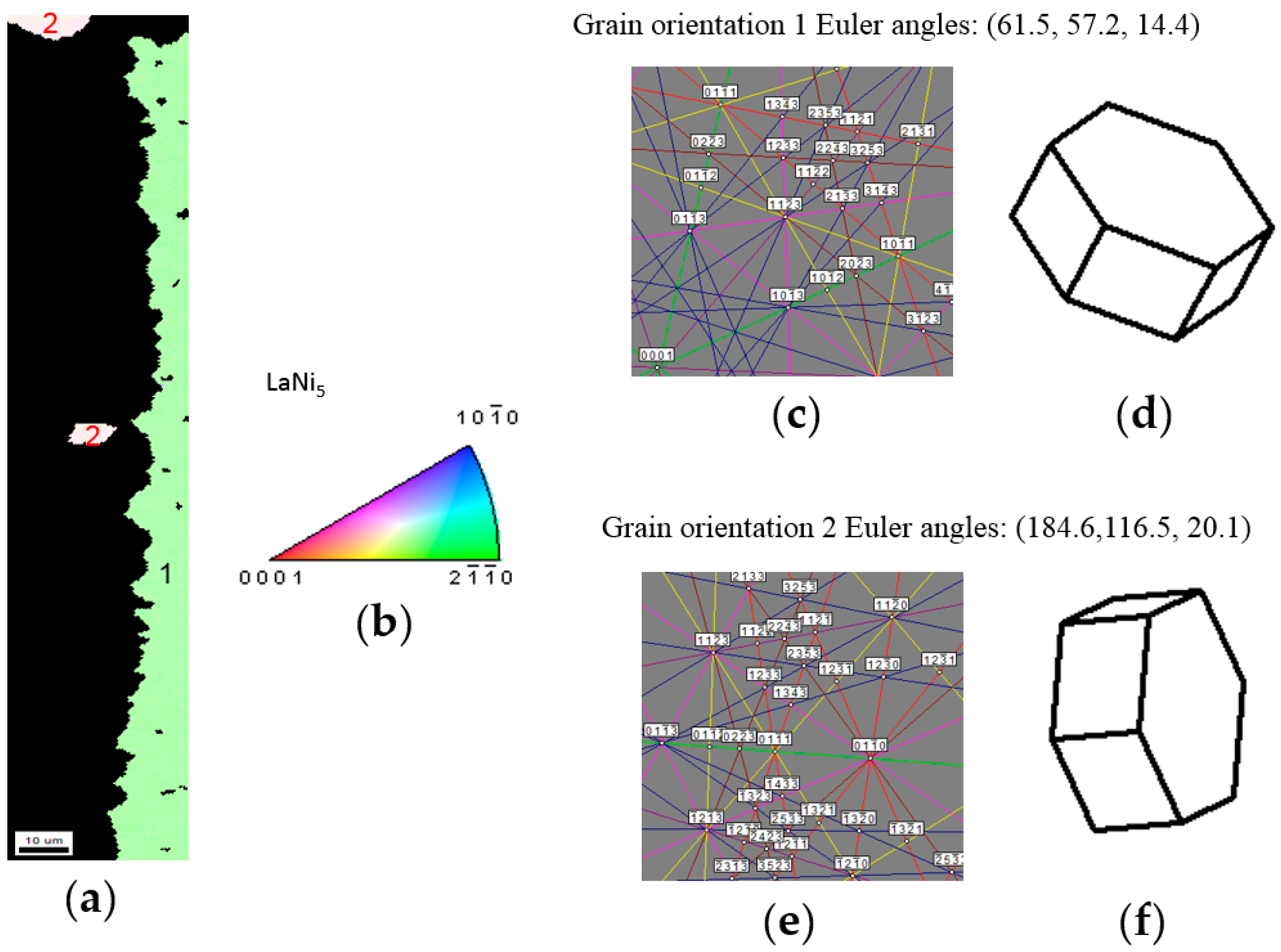
Inverse pole figure (IPF) and EBSD mapping, EBSD diffraction patterns, and crystal simulations of LaNi5 of the 16-h annealed sample are shown in Figure 8. In Figure 8a,b, color channels in red, green, and blue represent, [0001], [10 1 0], and [2 1 1 0] of LaNi5. Figure 8a shows only two grain orientations for LaNi5. Grain orientations are described in the form of the Euler angle in Figure 8c,e. Figure 8a shows that grains with orientation 2 are isolated and much smaller in abundance than those with orientation 1. The right side of Figure 8a (the center of alloy) is a single LaNi5 grain without reacting with Mg. The interaction with Mg stopped at the grain boundary between the LaNi5 phase with orientation 1 and the LaNi5 phase with orientation 2. This is the proof that the inter-diffusion of Mg into the host LaNi5 alloy is through a specific direction (presumable along the ab-plane) and stops at the grain boundary. Therefore, increasing the grain size of the host LaNi5 alloy can enhance the diffusion of Mg into the bulk.
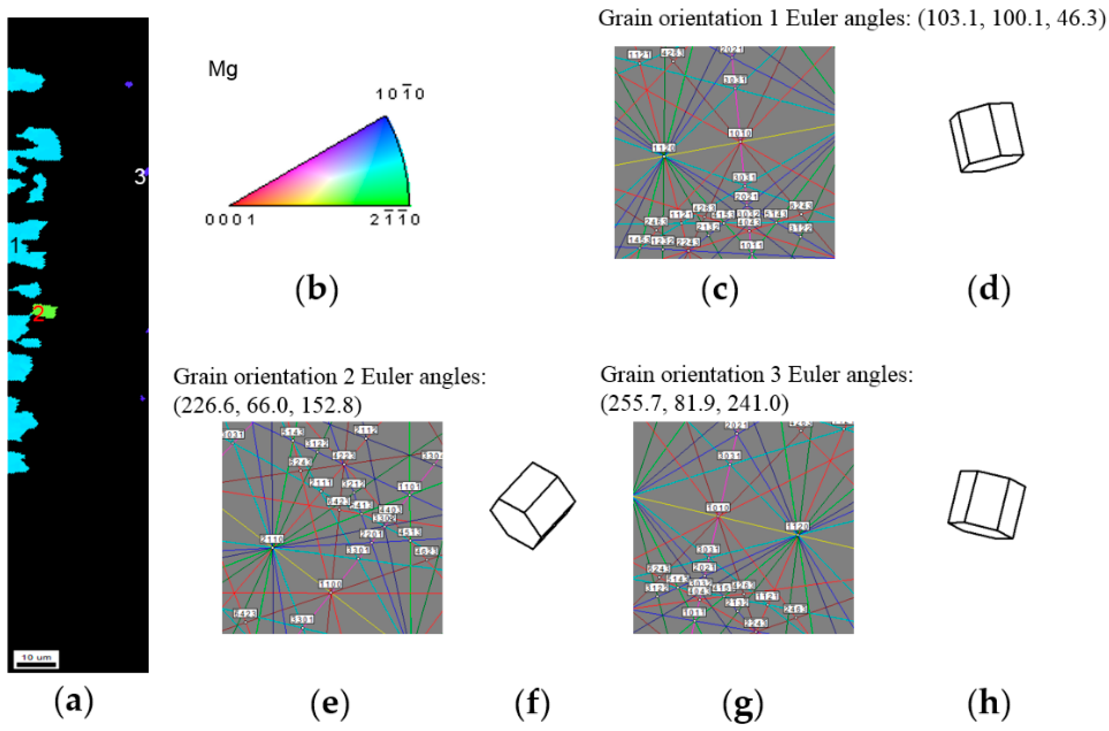
IPF and EBSD mapping, EBSD diffraction patterns, and crystal simulations of Mg of the 16-h annealed sample are shown in Figure 9. Three different crystallographic orientations are found for Mg. Grains with orientation 1 distribute at the edge of alloy and are the largest in size. Grains with orientation 3 distribute close to the center of alloy and are the smallest. After diffusing into the host, Mg first agglomerates into individual grains with the same crystallographic orientation (related to the host orientation) before reacting with the host to form the superlattice phases. It is interesting to find that the superlattice phases are formed by the reaction of LaNi5 with the Mg crystal but not the Mg vapor.

3.2.4. Ce2Ni7 and Pr2Ni7 Grain Distributions and Orientations

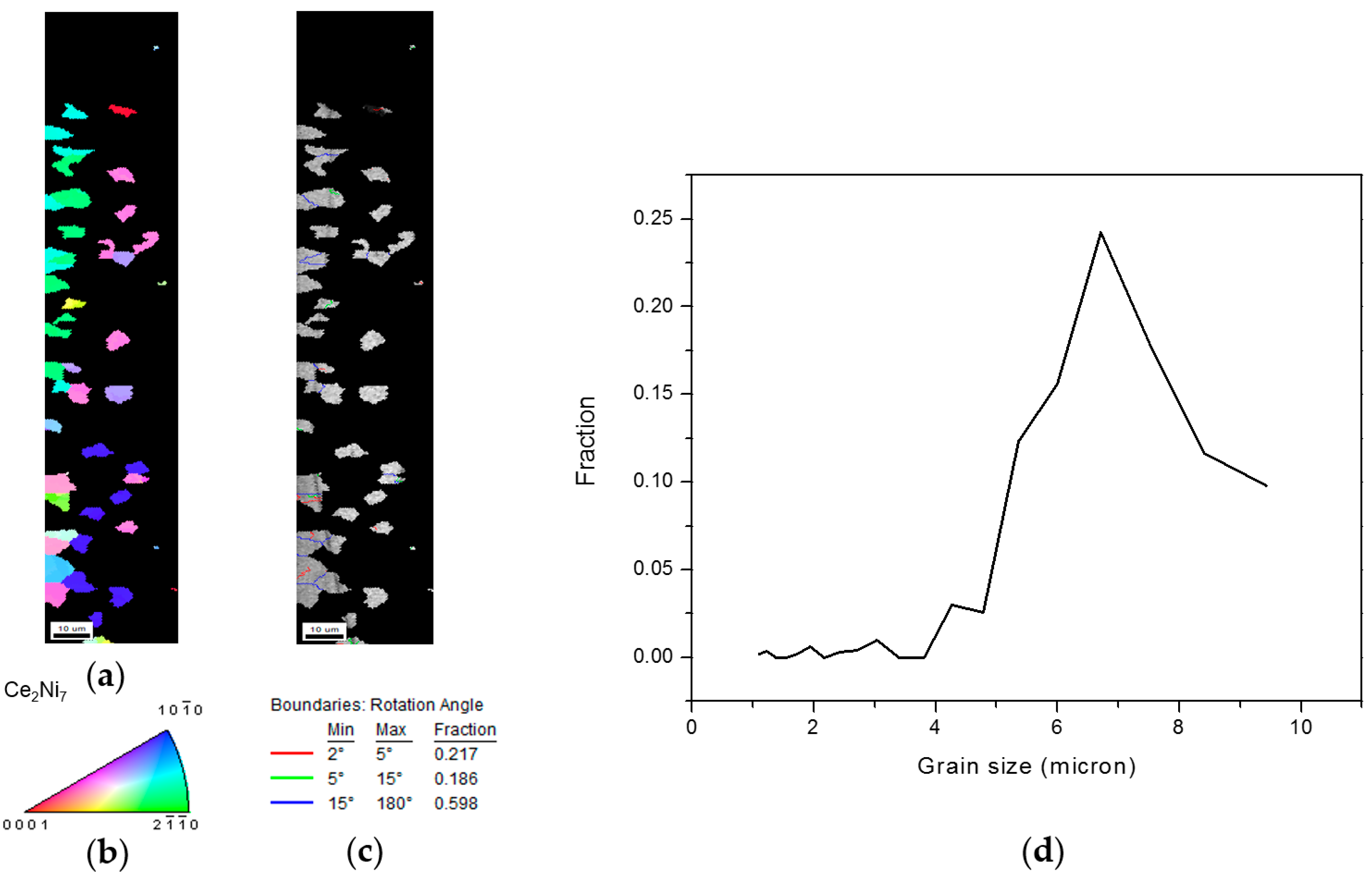
IPF and EBSD mapping, image quality (IQ) diffraction pattern and grain boundary map, and grain size distribution of Ce2Ni7 of the 16-h annealed sample are shown in Figure 10. Unlike LaNi5 and Mg, the Ce2Ni7 phase shows more grain orientations (Figure 10a). IQ patterns can be used to characterize the defect distribution in grains and is especially useful for the strain mapping [20]. Figure 10c shows that some grains are darker than the others, which indicates that concentrated defects and residual strains exist in these darker grains. A grain boundary is formed by the accumulation of edge dislocations. In this study, two types of boundaries are characterized: low-angle grain boundary (LAGB) and high-angle grain boundary (HAGB). LAGB subdivides a grain into two equiaxial cells and forms subgrains, which may increase the plastic deformation. In this study, we define the lattice misorientation of LAGB-separated grain zones to be from 2° to 15°. A grain boundary with a misorientation ≥ 15° is denoted as HAGB, which differentiates a grain from its initial microstructure and creates a new grain. Figure 10c indicates the grain boundary distribution of the Ce2Ni7 phase in the 16-h annealed sample. Amount of LAGBs in the Ce2Ni7 phase is 40.3%, which is much higher than that in the LaNi5 or Mg phase and suggests a high density of defects in the Ce2Ni7 grains. Grain size distribution is shown in Figure 10d. Average grain diameter of the Ce2Ni7 phase is 7 µm. IPF and EBSD mapping, EBSD diffraction patterns, and crystal simulations of Pr2Ni7 in the 16-h annealed sample are shown in Figure 11. Unlike Ce2Ni7, the Pr2Ni7 phase has only two different orientations and a smaller grain size of about 4 µm.

3.3. Alignment in Crystallographic Orientations

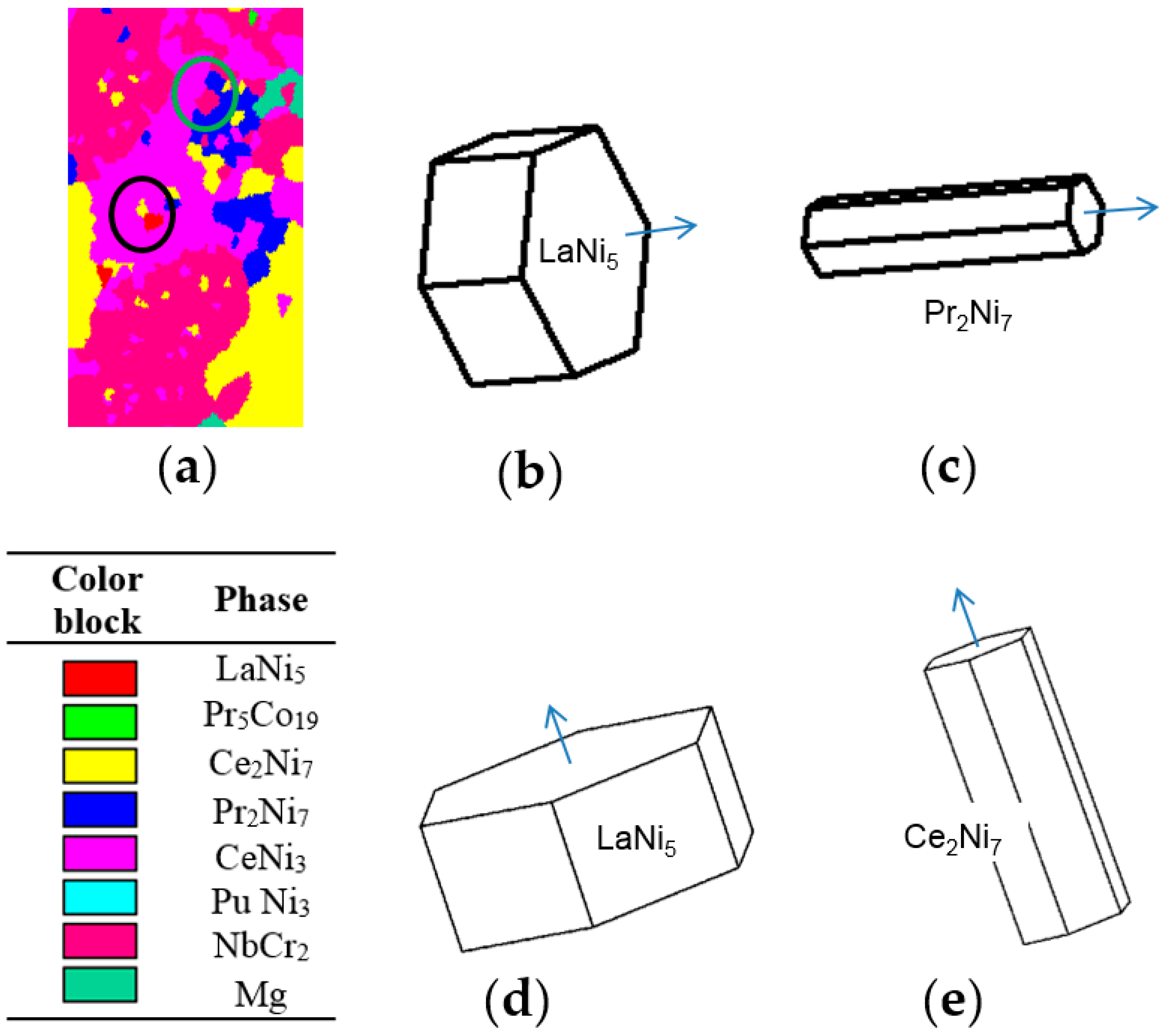
Figure 12a shows the EBSD phase identification mapping of the 8-h annealed sample. [0001]s of LaNi5 and Pr2Ni7 in the green circle are found to be parallel to each other, and [0001]s of LaNi5 and Ce2Ni7 in the black circle are also parallel (Figure 12b–e). This information gives a hint about the grain growth mechanism of the A2B7-type phases during the diffusion of Mg into the AB5 alloy. Structures of the La-Mg-Ni superlattice phases are composed of the A2B4 and the AB5 slabs [23]. The alignments of LaNi5 and Pr2Ni7 in the c-axis and LaNi5 and Ce2Ni7 in the c-axis imply that Mg diffuses into LaNi5 and forms the A2B4 slab through the ab-plane and, therefore, the c-axis orientation remains unchanged after the superlattice phase formation.

3.4. Effect of Process Temperature on Phase Development

EBSD mapping was performed in an area of 30 × 100 square microns close to the edge of each sample. The results may not be very accurate because of the limited sampling areas and large variations in distribution of the superlattice phases. Nevertheless, the calculated phase abundances are compared in Table 2. The conversion from LaNi5 to other phases is more complete with the increase in process time and reaches 98.2 wt % at a processing time of 32 h. Abundance of the most desirable Ce2Ni7 phase is about 25 wt % and not very sensitive to the processing time. Abundance of the A2B7 phases (both Ce2Ni7 and Pr2Ni7) increases from 42.5 to 45.8 wt % and reduces to 39.2 wt % as the processing time increases from 4 to 32 h. The unwanted AB2 and AB3 phases (with excessive Mg-content) cannot be eliminated with the increase in processing time. Future development work will focus on the reduction of the Mg-supply and/or addition of a second annealing treatment without Mg.
Grain size distributions of all four samples are also compared and listed in Table 3. The 4-h annealed sample has a heavy proportion of medium-size grains (5–12 μm) while the 8-h annealed sample has a much higher percentage of small grains (1–5 μm). Longer processing time (16- and 32-h) recovers the percentage of medium-size grains. The reason for the grain size evolution is not clear and requires further studies. The last comparison is on the distribution of misorientation angle in the grain boundary, which is shown in Table 4. Amount of HAGBs (15 to 180°) decreases with the increase in process time, which suggests the occurrence of lattice cracking.

4. Conclusions

A gaseous-state Mg-diffusion into an AB5 metal hydride alloy is demonstrated as an effective method to convert a LaNi5 alloy to a multi-phase superlattice alloy. Four La-Mg-Ni superlattice phases are identified by EBSD in the products: Ce2Ni7, Pr2Ni7, CeNi3, and PuNi3. Additionally, Mg and AB2 (with the hexagonal NbCr2 structure) phases are also found. Longer process time increases the LaNi5 conversion rate but shows no significant effect on increasing the abundance of the most desirable Ce2Ni7 phase. Defects are found abundantly in the Ce2Ni7 and Pr2Ni7 phases by EBSD, and distributions of the superlattice phases are not uniform. Future activities in reducing the Mg-loading, addition of a second annealing treatment, and increasing the initial grain size of the host alloy are suggested based on the findings in this study.

Supplementary Materials

The following are available online at https://www.mdpi.com/2313-0105/3/4/40/s1.

Acknowledgments

The authors would like to thank the following individuals for their help: Alan Chan, Jean Nei, and Diana Wong from BASF—Ovonic.

Author Contributions

Xin Zhao prepared the sample and Shuli Yan performed the EBSD study. Kwo-Hsiung and Simon Ng provided guidance and helped in manuscript preparation.

Conflicts of Interest

The authors declare no conflict of interest.

Abbreviations

RERare earth
MHMetal hydride
Ni/MHNickel/metal hydride
HRDHigh-rate dischargeability
EBSDElectron backscatter diffraction
SEMScanning electron microscope
EDSEnergy dispersive spectroscopy
BEIBackscattered electron image
SSDStatistically stored dislocations
GNDGeometrically necessary dislocations
IPFInverse pole figure
IQImage quality
LAGBLow-angle grain boundary
HAGBHigh-angle grain boundary

References

  1. Yasuoka, S.; Magari, Y.; Murata, T.; Tanaka, T.; Ishida, J.; Nakamura, H.; Nohma, T.; Kihara, M.; Baba, Y.; Teraoka, H. Development of high-capacity nickel-metal hydride batteries using superlattice hydrogen-absorbing alloys. J. Power Sources 2006, 156, 662–666. [Google Scholar] [CrossRef]
  2. Teraoka, H. Development of Low Self-Discharge Nickel-Metal Hydride Battery. Available online: http://www.scribd.com/doc/9704685/Teraoka-Article-En (accessed on 9 April 2016).
  3. Kai, T.; Ishida, J.; Yasuoka, S.; Takeno, K. The effect of nickel-metal hydride battery’s characteristics with structure of the alloy. In Proceedings of the 54th Battery Symposium in Japan, Osaka, Japan, 7–9 October 2013; p. 210. [Google Scholar]
  4. Takasaki, T.; Nishimura, K.; Saito, M.; Fukunaga, H.; Iwaki, T.; Sakai, T. Cobalt-free nickel-metal hydride battery for industrial applications. J. Alloys Compd. 2013, 580, S378–S381. [Google Scholar] [CrossRef]
  5. Teraoka, H. Development of Ni-MH EThSS with Lifetime and Performance Estimation Technology. In Proceedings of the 34th International Battery Seminar & Exhibit, Fort Lauderdale, FL, USA, 20–23 March 2017. [Google Scholar]
  6. Teraoka, H. Ni-MH Stationary Energy Storage: Extreme Temperature & Long Life Developments. In Proceedings of the 33th International Battery Seminar & Exhibit, Fort Lauderdale, FL, USA, 21–24 March 2016. [Google Scholar]
  7. Teraoka, H. Development of Highly Durable and Long Life Ni-MH Batteries for Energy Storage Systems. In Proceedings of the 32th International Battery Seminar & Exhibit, Fort Lauderdale, FL, USA, 9–12 March 2015. [Google Scholar]
  8. Ouchi, T.; Young, K.; Moghe, D. Reviews on the Japanese Patent Applications regarding nickel/metal hydride batteries. Batteries 2016, 2, 21. [Google Scholar] [CrossRef]
  9. Young, K.; Ouchi, T.; Nei, J.; Koch, J.M.; Lien, Y. Comparison among constituent phases in superlattice metal hydride alloys for batter applications. Batteries 2017, 3, 34. [Google Scholar] [CrossRef]
  10. Young, K.; Yasuoka, S. Past, present, and future of metal hydride alloys in nickel-metal hydride batteries. In Proceedings of the 14th International Symposium on Metal-Hydrogen Systems, Manchester, UK, 21–25 July 2014. [Google Scholar]
  11. Hayakawa, H.; Enoki, H.; Akiba, E. Annealing conditions with Mg vapor-pressure control and hydrogen storage characteristic of La4MgNi19 hydrogen storage alloy. Jpn. Inst. Met. 2006, 70, 158–161. (In Japanese) [Google Scholar] [CrossRef]
  12. Crivello, J.-C.; Zhang, J.; Latroche, M. Structural stability of ABy phases in the (La,Mg)–Ni system obtained by density functional theory calculations. J. Phys. Chem. 2011, 115, 25470–25478. [Google Scholar]
  13. Crivello, J.-C.; Gupta, M.; Latroche, M. First principles calculations of (La,Mg)2Ni7 hydrides. J. Alloys Compd. 2015, 645, S5–S8. [Google Scholar] [CrossRef]
  14. Young, K.; Ouchi, T.; Huang, B. Effects of annealing and stoichiometry to (Nd, Mg)(Ni, Al)3.5 metal hydride alloys. J. Power Sources 2012, 215, 152–159. [Google Scholar] [CrossRef]
  15. Zhao, X.; Li, B.; Zhu, X.; Han, S.; Yan, H.; Ji, L.; Wang, L.; Li, J.; Xiong, W.; Jia, T. Preparation Method of Low-Melting Point Metal Alloy. Chinese Patent Application 201,511,015,059, 31 December 2015. [Google Scholar]
  16. Young, K.; Chang, S.; Lin, X. C14 Laves phase metal hydride alloys for Ni/MH batteries applications. Batteries 2017, 3, 27. [Google Scholar] [CrossRef]
  17. Matiland, T.; Sitzman, S. Electron backscatter diffraction (EBSD) technique and materials characterizations examples. In Scanning Microscopy for Nanotechnology Techniques and Applications; Zhou, W., Wang, Z.L., Eds.; Springer: New York, NY, USA, 2007. [Google Scholar]
  18. Young, K.; Ouchi, T.; Liu, Y.; Reichman, B.; Mays, W.; Fetcenko, M.A. Structural and electrochemical properties of TixZr7‒xNi10. J. Alloy. Compd. 2009, 480, 521–528. [Google Scholar] [CrossRef]
  19. Liu, Y.; Young, K. Microstructure investigation on metal hydride alloys by electron backscatter diffraction technique. Batteries 2016, 2, 26. [Google Scholar] [CrossRef]
  20. Shen, H.; Young, K.; Meng, T.; Bendersky, L.A. Clean grain boundary found in C14/body-center-cubic multi-phase metal hydride alloys. Batteries 2016, 2, 22. [Google Scholar] [CrossRef]
  21. Liu, J.; Han, S.; Li, Y.; Zhang, L.; Zhao, Y.; Yang, S. Phase structures and electrochemical properties of La–Mg–Ni-based hydrogen storage alloys with superlattice structure. Int. J. Hydrogen Energy 2016, 41, 20261–20275. [Google Scholar] [CrossRef]
  22. Buschow, K.H.; Van Mal, H.H. Phase relations and hydrogen absorption in the lanthanum-nickel system. J. Less Common Met. 1972, 29, 203–210. [Google Scholar] [CrossRef]
  23. Young, K.; Nei, J. The current status of hydrogen storage alloy development for electrochemical applications. Materials 2013, 6, 4574–4608. [Google Scholar] [CrossRef] [PubMed]
  24. Chang, S.; Young, K.-H.; Nei, J.; Fierro, C. Reviews on the US Patents regarding nickel/metal hydride batteries. Batteries 2016, 2, 10. [Google Scholar] [CrossRef]
  25. Young, K.; Ouchi, T.; Nei, J.; Yasuoka, S. Fe-substitution for Ni in misch metal-based superlattice hydrogen absorbing alloys—Part 1. Structural, hydrogen storage, and electrochemical properties. Batteries 2016, 2, 34. [Google Scholar] [CrossRef]
  26. Wright, S.I.; Nowell, M.M.; Field, D.P. A review of strain analysis using electron backscatter diffraction. Microsc. Microanal. 2011, 17, 316–329. [Google Scholar] [CrossRef] [PubMed]
  27. Winkelmann, A. Dynamical effects of anisotropic inelastic scattering in electron backscatter diffraction. Ultramicroscopy 2008, 108, 1546–1550. [Google Scholar] [CrossRef] [PubMed]
  28. Keller, R.R.; Roshko, A.; Geiss, R.H.; Bertness, K.A.; Quinn, T.P. EBSD measurement of strains in GaAs due to oxidation of buried AlGaAs layers. Microelecron. Eng. 2004, 75, 96–102. [Google Scholar] [CrossRef]
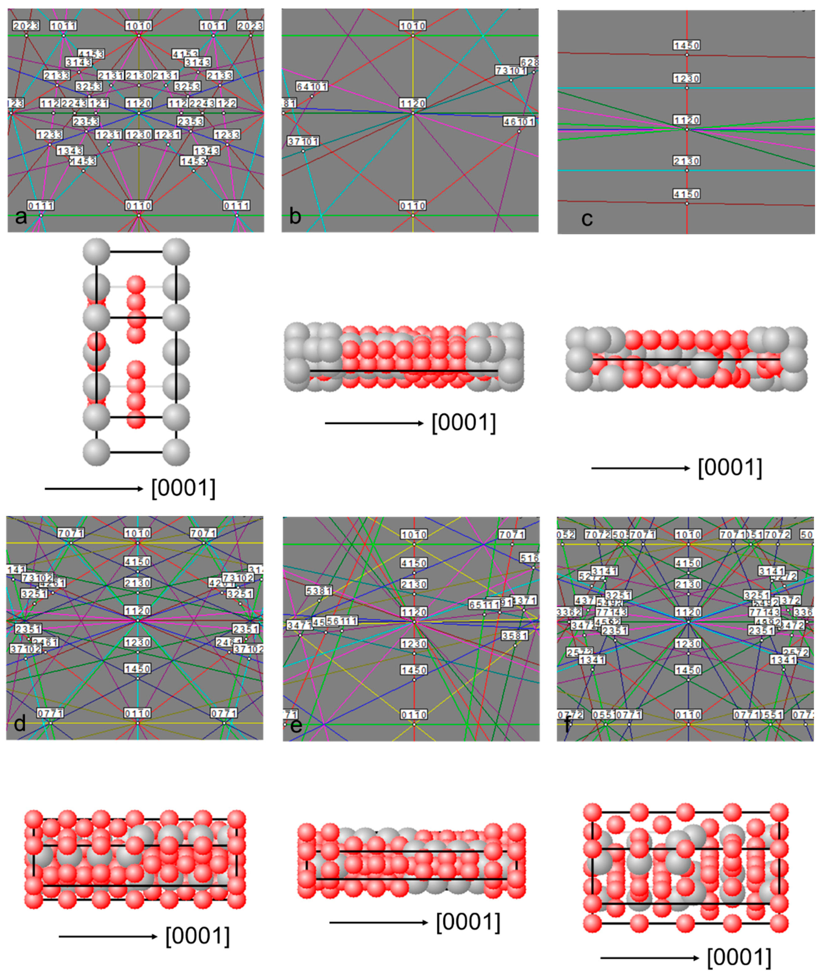
Figure 1. Computer-generated EBSD patterns for the (11 2 0) planes of (a) LaNi5; (b) Pr5Co19; (c) Nd5Co19; (d) Ce2Ni7; (e) Pr2Ni7; (f) CeNi3; (g) PrNi3; and (h) NbCr2 (hexagonal).
Batteries 03 00040 g001aBatteries 03 00040 g001b
Figure 2. SEM-BEI of the 8-h annealed sample. Structures of spots Z1 to Z6 and A to C were studied by EBSD. Compositions of spots Y1 to Y13 were measured by EDS.
Batteries 03 00040 g002
Figure 3. Original EBSD patterns, fitted patterns, and simulations of grain orientation from spots (a) Z1: LaNi5; (b) Z2: Ce2Ni7; (c) Z3: Pr2Ni7; (d) Z4: CeNi3; (e) Z5: Mg; and (f) Z6: NbCr2 of the 8-h annealed sample (Figure 2).
Batteries 03 00040 g003aBatteries 03 00040 g003b
Figure 4. Comparison of original and computer-generated EBSD patterns from spots (a) A: LaNi5; (b) B: Ce2Ni7; and (c) C: Pr2Ni7 of the 8-h annealed sample (Figure 2). Solid-color lines indicate the width of computer-generated band. Dashed-black lines show the width of actual band. A new band (B2) and bands with a slight rotation (A1), a shift (A2), a narrower width (B1), and a wider width (C1) are observed.
Batteries 03 00040 g004
Figure 5. Schematic diagrams of (a) a regular crystal lattice; (b) a strained lattice with uniaxial lengthened bonds; (c) a bent lattice; (d) a distorted lattice with symmetric vacancy defects; and (e) a lattice with a subgrain boundary.
Batteries 03 00040 g005
Figure 6. (a1,b1,c1,d1) SEM-BEIs and elemental mappings of (a2,b2,c2,d2) La, (a3,b3,c3,d3) Ni, and (a4,b4,c4,d4) Mg of the 4 h-, 8 h-, 16 h-, and 32-h annealed samples, respectively.
Batteries 03 00040 g006
Figure 7. EBSD phase identification mapping and quantification of the 16-h annealed sample. The grain tolerance angle is 15°, and the minimum grain size is 3 μm.
Batteries 03 00040 g007
Figure 8. (a) IPF and EBSD mapping; (b) color assignment; (c) EBSD pattern for grain orientation 1 and (d) its corresponding crystal simulation; and (e) EBSD pattern for grain orientation 2 and (f) its corresponding crystal simulation of the LaNi5 phase of the 16-h annealed sample.
Batteries 03 00040 g008
Figure 9. (a) IPF and EBSD mapping; (b) color assignment; (c) EBSD pattern for grain orientation 1 and (d) its corresponding crystal simulation; (e) EBSD pattern for grain orientation 2 and (f) its corresponding crystal simulation; and (g) EBSD pattern for grain orientation 3 and (h) its corresponding crystal simulation of the Mg phase of the 16-h annealed sample.
Batteries 03 00040 g009
Figure 10. (a) IPF and EBSD mapping; (b) color assignment; (c) IQ diffraction pattern and grain boundary map; and (d) grain size distribution of the Ce2Ni7 phase of the 16-h annealed sample.
Batteries 03 00040 g010
Figure 11. (a) IPF and EBSD mapping; (b) color assignment; (c) EBSD pattern for grain orientation 1 and (d) its corresponding crystal simulation; and (e) EBSD pattern for grain orientation 2 and (f) its corresponding crystal simulation of the Pr2Ni7 phase of the 16-h annealed sample.
Batteries 03 00040 g011
Figure 12. Crystallographic orientation alignments in [0001] demonstrated by (a) an IPF-EBSD map; orientations of (b) LaNi5 and (c) neighboring Pr2Ni7 in the green circle; and orientations of (d) LaNi5 and (e) neighboring Ce2Ni7 in the black circle of the 8-h annealed sample.
Batteries 03 00040 g012
Table 1. Chemical compositions (in at%) from spots Y1 to Y13 of the 8-h annealed sample (Figure 2).
SpotMgLaNiNi/(La + Mg)
Y124.0116.1959.791.49
Y216.4212.9470.642.41
Y313.1214.0972.782.67
Y41.2916.1182.64.75
Y50.0016.4583.555.08
Y60.2816.2783.455.04
Y70.2916.1083.615.10
Y80.0016.7183.294.98
Y90.0015.8284.185.32
Y100.0016.7283.284.98
Y110.0016.2483.765.16
Y121.0016.2682.744.79
Y138.3215.1676.543.26
Table 2. Phase abundances (in wt %) obtained by EBSD mapping of the 4-h, 8-h, 16-h, and 32-h annealed samples with a grain tolerance angle of 5° and a minimum grain size of 2 μm.
Phase4 h8 h16 h32 h
LaNi513.25.54.21.8
Ce2Ni723.527.327.625.5
Pr2Ni719.018.516.313.7
CeNi322.619.526.421.0
PuNi30.50.20.50.5
NbCr216.225.522.330.3
Mg4.93.42.87.2
Table 3. Grain size distributions of the 4-h, 8-h, 16-h, and 32-h annealed samples.
Grain Size (μm)4 h8 h16 h32 h
1 to 524%79%35%37%
5 to 1261%16%48%49%
>1215%5%16%14%
Table 4. Grain boundary distributions of the 4-h, 8-h, 16-h, and 32-h annealed samples.
Grain Boundary (°)4 h8 h16 h32 h
2 to 511.3%14.4%22.3%22.1%
5 to 154.3%2.5%0.7%11.4%
15 to 18084.4%83.1%77.0%55.5%