Article

Fault Tree Analysis of Lithium-Ion Battery Pack Fire Risk for Electric Vehicle Applications

1
University Grenoble Alpes, CEA, LITEN, DEHT, 38000 Grenoble, France
2
Aix Marseille University, Centrale Marseille, CNRS, LMA, 13453 Marseille, France
*
Author to whom correspondence should be addressed.
Batteries 2026, 12(7), 252; https://doi.org/10.3390/batteries12070252
Submission received: 18 June 2026 / Revised: 7 July 2026 / Accepted: 8 July 2026 / Published: 13 July 2026

Abstract

Battery pack fires remain a critical safety concern for lithium-ion battery systems. This study presents a comprehensive application of Fault Tree Analysis (FTA) to identify and structure the sequences of failures that may lead to a battery pack fire. A detailed fault tree is developed for a cell–module–pack architecture equipped with a thermal management system, enabling a clear representation of failure pathways. The analysis highlights four main origins of battery pack fire. Each intermediate scenario is described through dedicated branches of the fault tree to enhance clarity and facilitate its adoption for other battery pack designs and use-cases. As most failure modes involved in battery pack fire do not have reliable probability data available or exhibit strong dependency on usage conditions, a fuzzy logic-based expert approach is employed. Probabilistic data are collected through a questionnaire, allowing the assignment of probabilities to undocumented failure events. A quantified use-case is presented for an electric vehicle, illustrating the practical application of the methodology. The objective of this work is to demonstrate a structured and adaptable methodology for applying FTA to lithium-ion battery pack fire risk analysis. The resulting fault tree, provided as open-access supplementary material, aims to support safety analysis, highlight critical protection failures, and identify current limitations in battery pack safety systems. It can also help identify critical components in order to support the development of rapid and targeted diagnostic strategies for battery packs throughout their lifetime.

1. Introduction

The global adoption of electric vehicles (EVs) has been increasing steadily worldwide, and this growth is expected to accelerate in the coming years. As a key enabler of transport sector de-carbonization, EVs play a crucial role in reducing greenhouse gas emissions and dependence on fossil fuels [1]. Lithium-ion batteries, which are the predominant energy storage technology in EVs [2,3], have undergone significant advancements in terms of energy density [4], charging time [5,6], and cost reduction [4]. These continuous improvements have greatly contributed to enhancing user acceptance. Today, electric vehicles account for approximately one-fifth of all new vehicle sales worldwide [7].
They are equipped with lithium-ion battery packs, a technology associated with specific safety challenges. Alongside the increasing number of electric vehicles, a rise in safety-related incidents has also been observed [8]. Indeed, the use of lithium-ion cells, the primary components of these batteries, outside their specified operating conditions such as overcharging [9,10], deep discharging [10,11], excessively fast charging [11] or exposure to high and low temperatures [9,11] can lead to degradation mechanisms and thermal runaway. These risks have significant implications for the safety of both people and goods [12], and they can strongly constrain the storage and transportation of batteries.
In this context, understanding the failure causes of battery packs, as well as their interactions, is essential. Recent studies have increasingly used Fault Tree Analysis (FTA) to examine the safety and reliability of lithium-ion batteries. Gravante et al. [13] introduce a graph-based method to track failure paths within a pack, while Chauhan et al. [14] propose a component-level Failure Modes and Effects Analysis (FMEA) that considers operational and environmental factors. Jiang et al. [15] combine polymorphic theory, fuzzy logic, group decision-making, and the classical FTA model for both functional and degraded-state failures. Hu et al. [16] develop a fuzzy FTA framework with experimental tests to identify the most critical EV (electric vehicle) battery failure, and Huang et al. [11] apply fuzzy FTA to battery transport by sea, providing a reference for different batteries and scenarios.
This study presents a Fault Tree Analysis of a lithium-ion battery pack, developed by a panel of battery-pack experts. The primary objective is to identify the sequences of events that can lead to a battery pack fire, in order to highlight critical components, propose safety redundancies, and support targeted battery diagnostics. The FTA method is adopted because it provides a clear visual representation of failure paths. A detailed explanation of the FTA methodology is provided in Section 2.1.
A key step in the methodology consists of assigning probabilities to the different failure events represented in the fault tree. For battery pack fire, a major challenge is the lack of reliable probabilistic data for many failure modes: most are either unavailable in the literature or highly dependent on battery design and operating conditions. To overcome this limitation and to obtain probabilities applicable to the use-case, a fuzzy logic-based method was employed. A questionnaire was distributed to a panel of 150 battery experts to estimate probabilities for failure modes that are not documented. The fuzzy logic approach is described in Section 2.2. While this study focuses on an electric vehicle use-case described in Section 2.2, the methodology and the resulting fault tree can be extended to other applications.
Finally, the presentation of the resulting fault tree, along with the details of each branch and the associated failure sequences, is provided in Section 3.1. A case study applying probabilities collected from the literature and via a fuzzy logic approach is presented in Section 3.2. The main objective of this study is therefore to present a detailed fault tree and provide a framework for its interpretation, making it applicable to any case study.

2. Materials and Methods

2.1. Fault Tree Analysis Methodology

Fault Tree Analysis (FTA) is an analytical method used to identify and evaluate the combinations of faults and events that can lead to a predefined undesired system-level event, defined as the top event. It represents the logical relationships between basic events and intermediate events using Boolean logic gates, such as AND and OR, enabling the assessment of system reliability and safety [17]. The representation of the elements constituting an FTA is shown in Figure 1.
An FTA can be used to estimate the probability of the top event based on the probabilities of the individual basic events by combining them through AND and OR gates. The probability associated with an AND gate is given by Equation (1), while the probability associated with an OR gate is given by Equation (2).
P E A N D = i = 1 n P ( E i )
where P(EAND) is the probability of the output event EAND, and P(Ei) the probability of occurrence of the input event Ei.
P E O R = i = 1 n P ( E i )
where P(EOR) is the probability of the output event EOR, and P(Ei) the probability of occurrence of the input event Ei.

2.2. Basic Event Probability Determination Based on Fuzzy Logic

In a first step, an initial group of RTO (Research and Technology Organization) experts with knowledge in lithium-ion technologies from different domains (electrical architecture, lithium-ion cell chemistry, thermal management, assembly, disassembly and mechanical design) is constituted to develop a Failure Modes and Effects Analysis (FMEA), which is not discussed here. This analysis enabled the identification of potential failure modes that may occur in a lithium-ion battery pack. A literature review is conducted for all identified failure modes but for most of these failures, no associated probabilistic data are available. Consequently, a fuzzy logic-based approach is used to collect probabilistic data using the expertise of lithium-ion battery pack specialists. Although effective, this approach relies on multiple and often imprecise criteria, making it difficult for experts to assign exact numerical values. Fuzzy logic therefore provides a relevant solution, as it allows expert judgments to be expressed using linguistic terms that are converted into numbers. Consequently, the combination of FTA with fuzzy logic is well suited to risk evaluation and identification. To apply this technique, all identified failure modes are subsequently compiled into a questionnaire and distributed to a panel of approximately 150 battery experts, who also represent diverse areas of expertise. For each failure mode the experts were asked to assess its likelihood of occurrence by selecting one of five predefined linguistic terms: very likely, likely, unlikely, very unlikely, or unknown. A numerical probability is predefined but not disclosed to the questionnaire respondents; the corresponding quantification is presented in Table 1. The correspondence scale is established based on failure values reported in the literature, in particular the failure rate of a lithium-ion cell, which is on the order of 1 × 10⁻⁸ h−1 (per hour) [18]. After collecting the questionnaires, the linguistic assessments were converted into their corresponding numerical values using the predefined fuzzy scale. For each basic event, the numerical values obtained from the experts were aggregated using the arithmetic mean to determine the final occurrence probability used in the quantitative Fault Tree Analysis. It should be noted that the linguistic terms used in Table 1 represent relative likelihood levels within the proposed fuzzy scale and should not be interpreted as absolute failure frequencies. Due to the limited availability of statistical data for specific lithium-ion battery failure modes, these categories are used to translate expert knowledge into quantitative values suitable for Fault Tree Analysis.
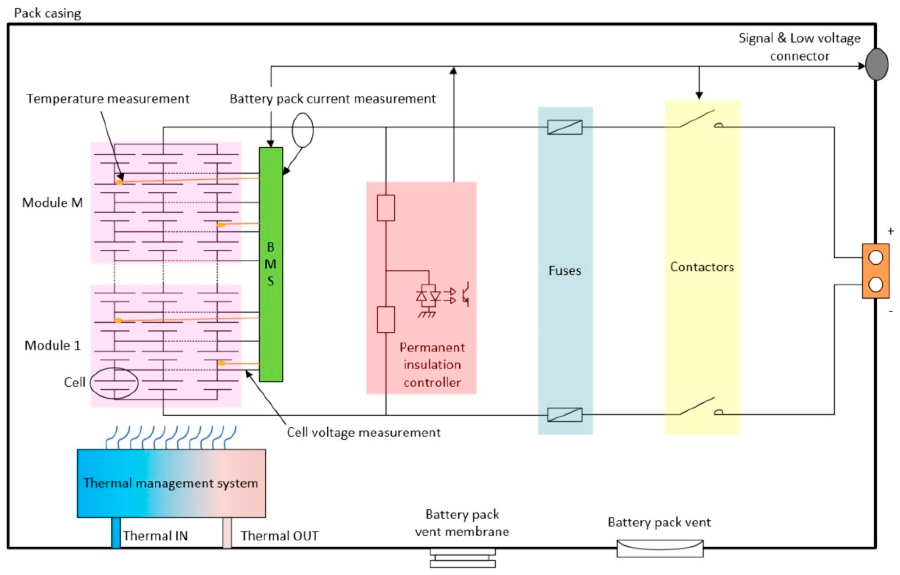
Along with the questionnaire, the experts are provided with the following use-case context: “an electric vehicle with a driving range of 400 km, equipped with a battery pack based on a cell–module–pack architecture and a thermal management system, operating in the Isère department, in France.” In addition, an electrical architecture of the battery pack under study is supplied, as shown in Figure 2.
This approach therefore makes it possible to estimate probabilities for failure modes for which data are not available in the literature. However, this technique involves several sources of uncertainty. The objective of this study is not to discuss the absolute values obtained, but rather to illustrate the application of the FTA methodology to a lithium-ion battery pack. The calculation of the overall probabilities must be reassessed for each battery pack and each specific application. A representative example is provided in Section 3.2.

3. Results and Discussions

3.1. Detailed Description of Fault Tree Branches

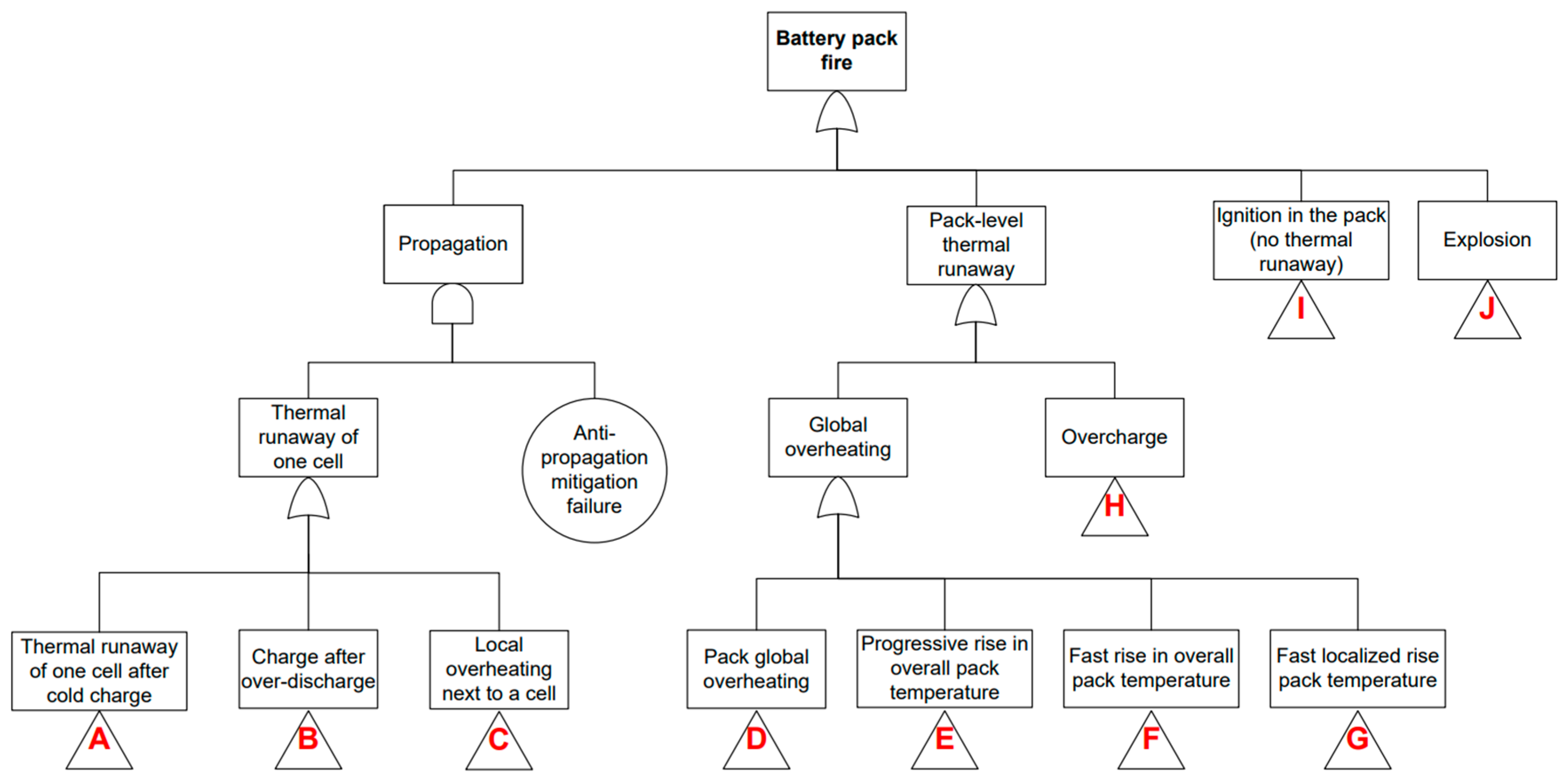
The global fault tree, which describes the sequences of failures that may lead to the top event, the “battery pack fire”, is shown in Figure 3. The battery pack considered in this study follows a cell–module–pack architecture and is equipped with a thermal management system, as illustrated in Figure 2.
There are four distinct possible causes for battery pack fire. First, it may arise from the propagation of a cell thermal runaway. Thermal runaway is directly associated with an internal short-circuit which occurs in the case of an insulation fault, leading to the release of a large amount of energy from the cell [18]. An insulation fault may result from charging at cold temperature [branch A], charging after over-discharging [branch B], or the presence of local overheating [branch C]. Once an internal short-circuit occurs, the cell goes into thermal runaway, which can propagate to neighboring cells in the event of a failure of the anti-propagation mitigation system.
Moreover, certain events can lead to thermal runaway and a generalized battery pack fire: global overheating at the pack level [branch D], a progressive rise in overall pack temperature [branch E], a fast rise in overall pack temperature [branch F], or a fast localized rise in pack temperature [branch G]. In addition, thermal runaway may also be triggered by battery pack overcharge [branch H]. Finally, the battery pack fire may occur as a result of ignition in the battery pack without thermal runaway [branch I], or an explosion [branch J].
All branches from A to J are detailed in the remainder of the article. The fault tree is provided as open-access Supplementary Materials associated with this publication and is available in the Supplementary Materials section.

3.1.1. Thermal Runaway of One Cell After Cold Charge (Branch A)

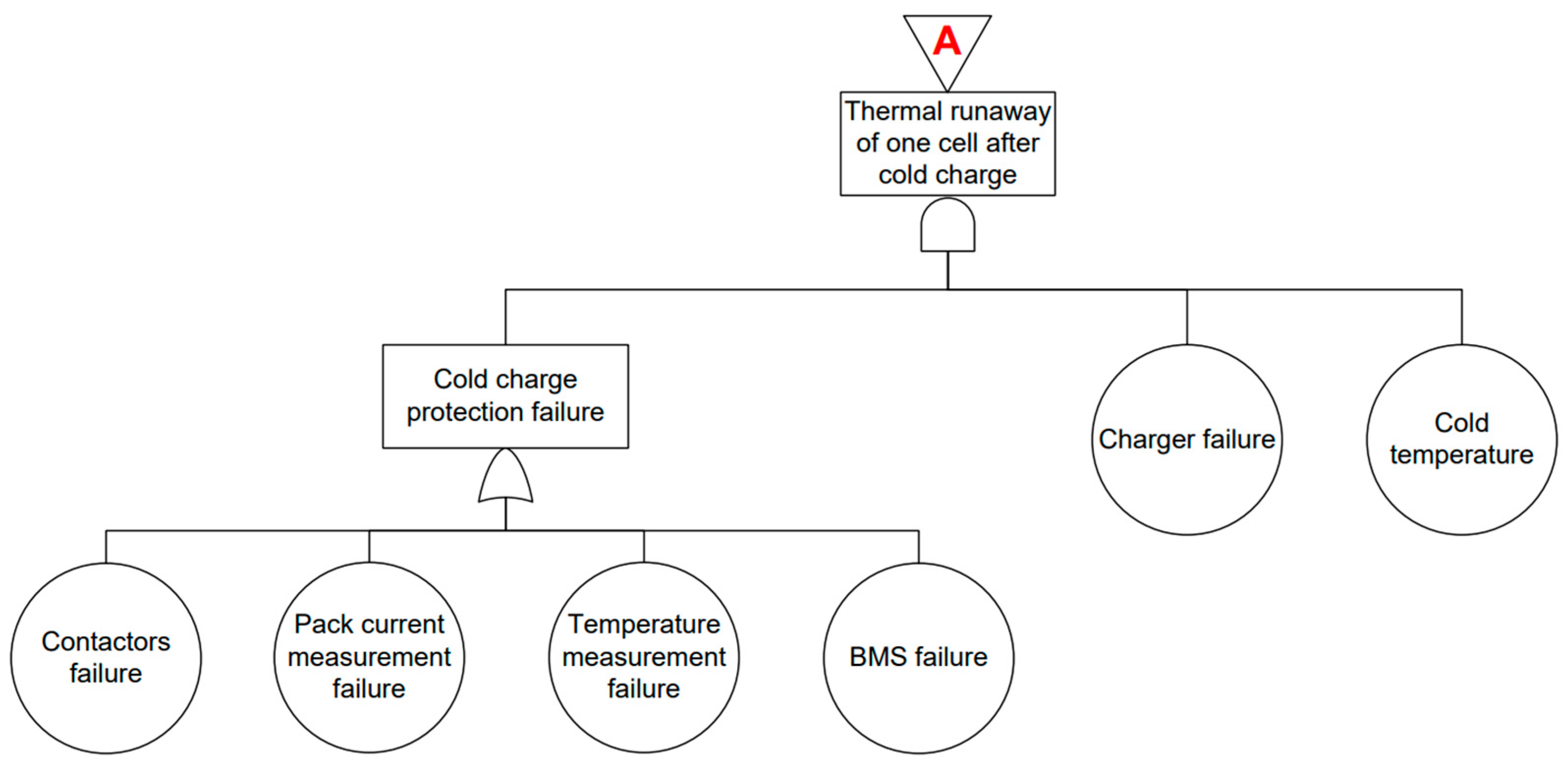
Thermal runaway of one cell after cold charging may occur when the cold charge protection is ineffective. During charging, the Battery Management System (BMS) monitors the battery pack temperature and the pack current. If the measured temperature or current exceeds predefined limits, the BMS can command the opening of the contactors to protect the battery pack. Under normal conditions, the BMS also controls the charger to prevent charging at low temperatures. In case of malfunction, this protective action may not be applied, and charging at temperatures below 0 °C can occur, leading to a cold-charging failure [19]. Charging at low temperatures promotes lithium plating at the anode and the growth of lithium dendrites. These dendrites may penetrate the separator, causing an internal short-circuit that can trigger thermal runaway of the cell. The FTA of thermal runaway of one cell after cold charge is shown in Figure 4.

3.1.2. Charge After Over-Discharge (Branch B)

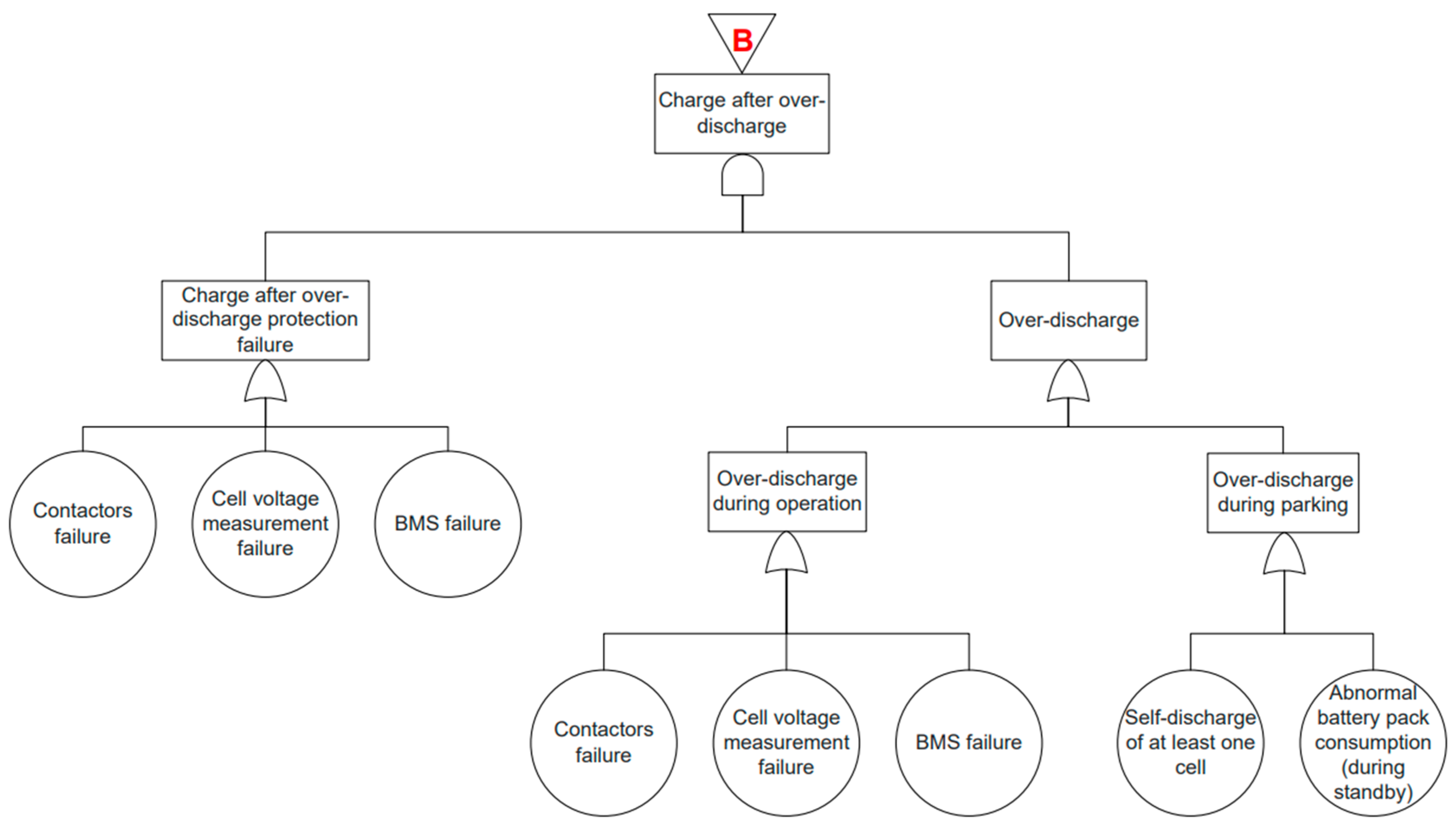
An over-discharge may occur either during vehicle operation or while the vehicle is parked. During operation, the BMS monitors cell voltages and commands the opening of the contactors when necessary. During normal operation, this function prevents cells from being discharged below safe limits but if any of these components malfunction, over-discharge may occur. While the vehicle is parked, prolonged storage may lead to over-discharge due to the self-discharge of at least one cell or abnormal battery pack consumption during the standby. Over-discharge conditions promote an increase in the anode potential, leading to the dissolving of the copper collector and the formation of copper dendrites on the cathode side. When over-discharge occurs, the BMS may inhibit recharging by monitoring cell voltages and preventing contactor closure if any cell voltage falls below a predefined threshold. The FTA of charge after over-discharge is shown in Figure 5.

3.1.3. Local Overheating (Branch C)

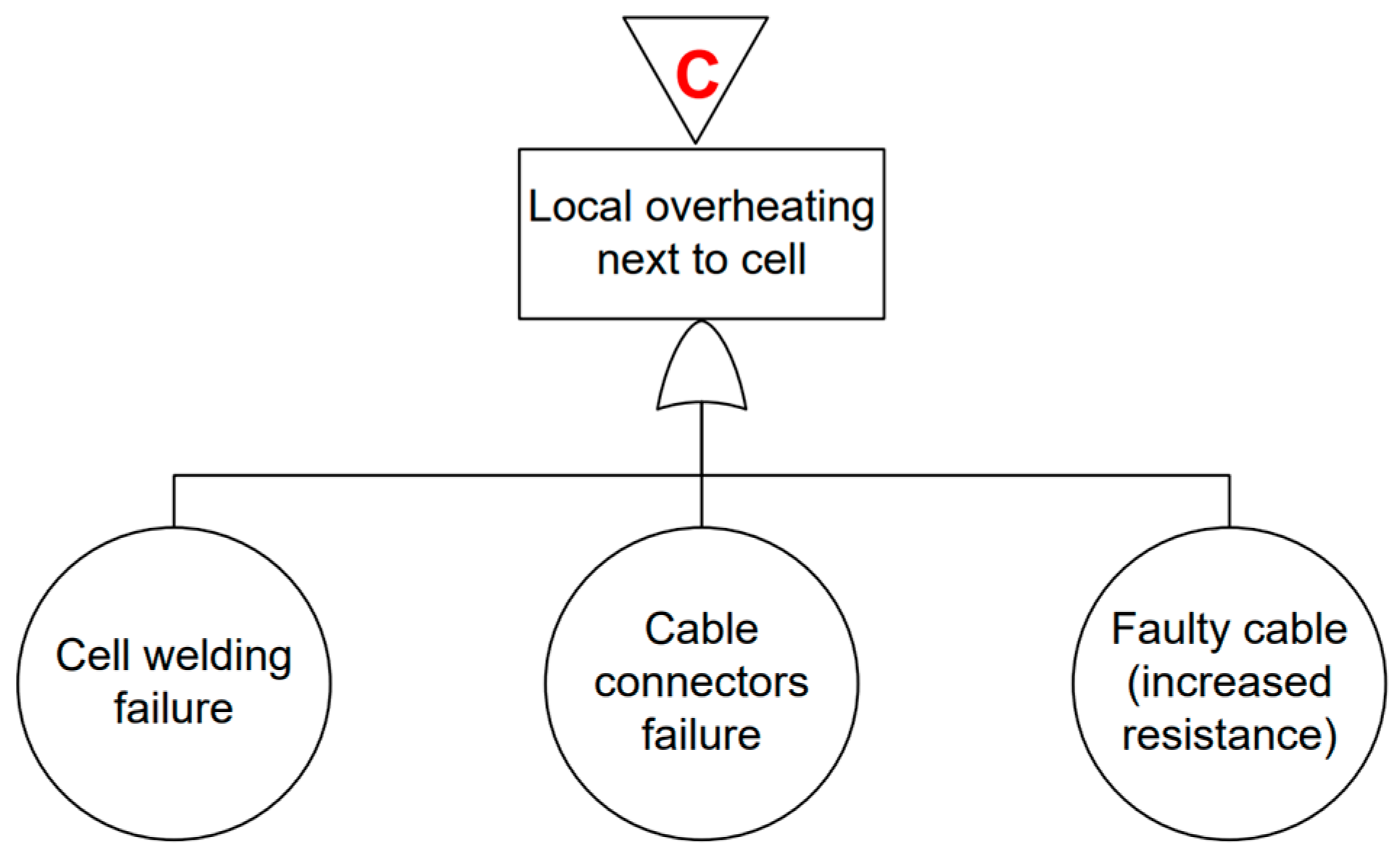
Local overheating, or a hot spot, may occur due to Joule heating and corresponds to a localized increase in electrical resistivity within the battery pack. In the absence of faults, cell welding, cables and connectors ensure low-resistance current paths. An electrical degradation of these components can locally increase resistance. When this phenomenon occurs next to a cell, the resulting heat generation can lead to a significant over-temperature, potentially initiating further cell degradation or failure.
The FTA of local overheating is shown in Figure 6.

3.1.4. Pack Global Overheating (Branch D)

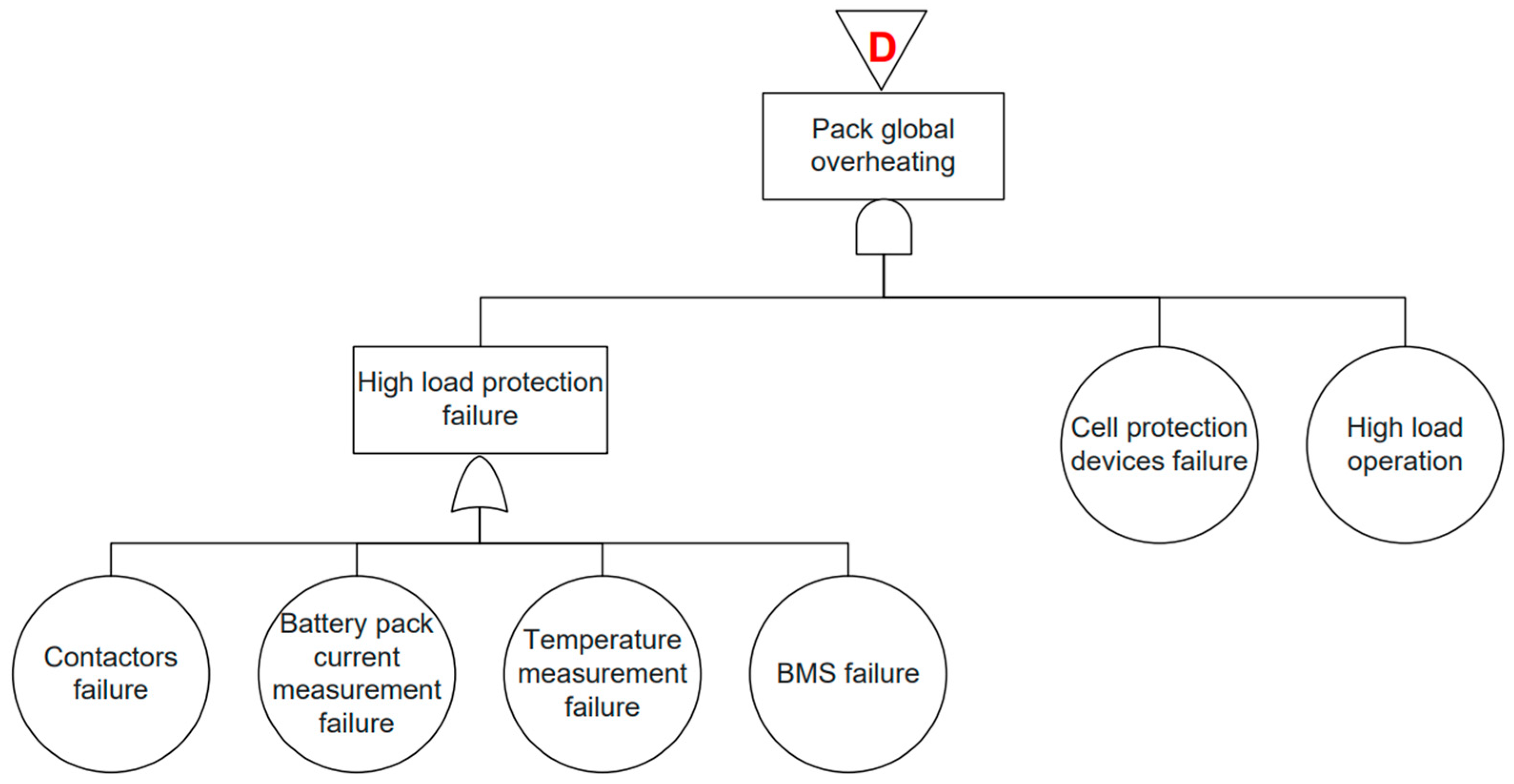
Pack global overheating may occur in the event of high load operation, combined with the failure of cell protection devices and high load protection failure. The BMS continuously monitors the battery pack current and temperature and commands the opening of the contactors when predefined limits are exceeded. If any of these components malfunction, high-load operation may persist without limitation, leading to a global overheating of the battery pack. This can lead to the separator melting or cathode destabilization, potentially resulting in an internal short-circuit.
The FTA of pack global overheating is shown in Figure 7.

3.1.5. Progressive Rise in Overall Pack Temperature (Branch E)

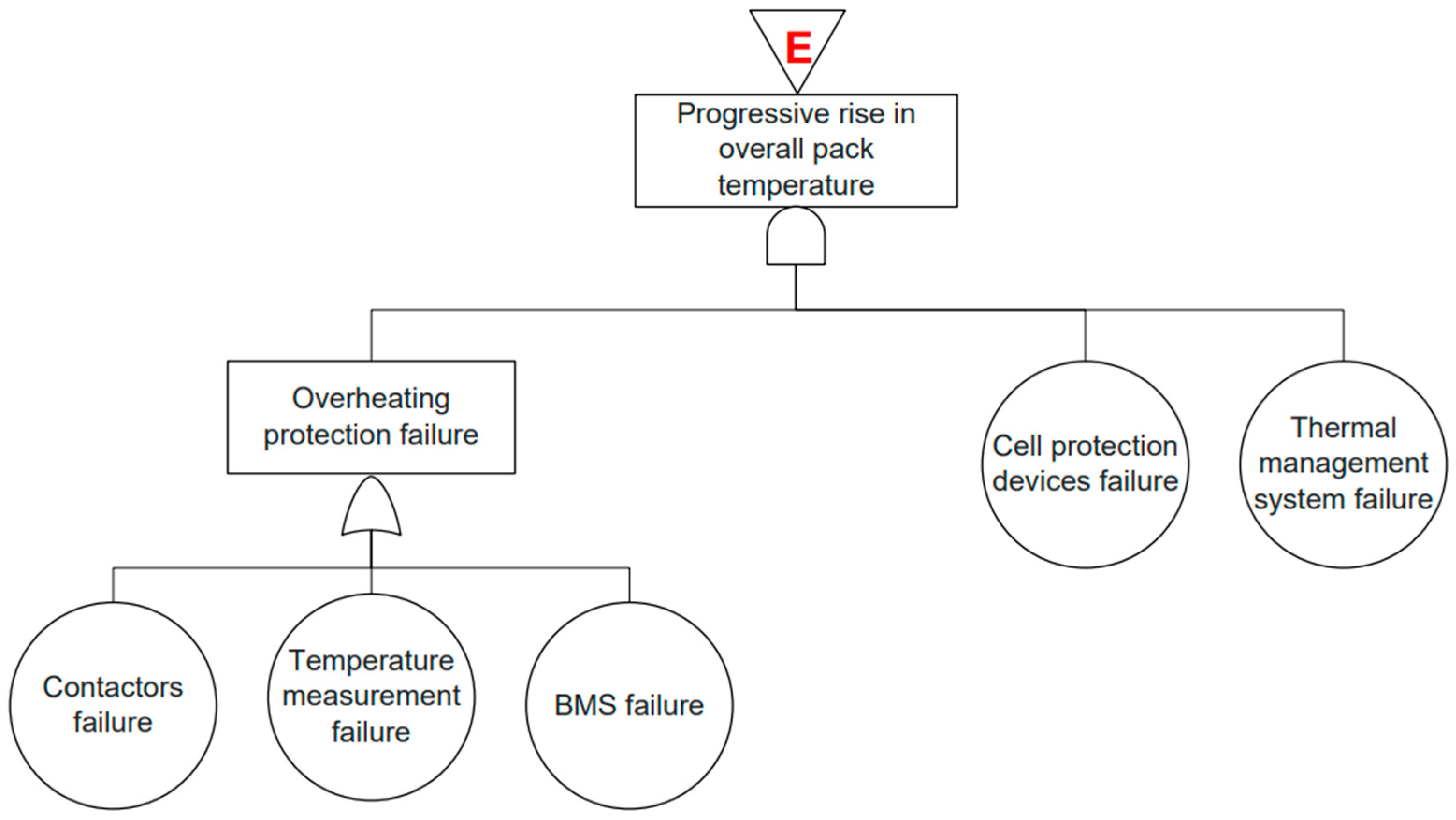
Progressive battery pack overheating may occur in the event that the thermal regulation of the pack is ineffective, combined with the failure of cell protection devices and overheating protection failure. When the thermal management system (TMS) fails, for example by stopping its operation or by heating the pack instead of cooling it, the overall pack temperature gradually increases. Under normal conditions, the BMS monitors the pack temperature and opens the contactors to interrupt operation and limit the temperature rise. If any of these components malfunction, this protective action cannot be ensured, allowing a progressive rise in overall pack temperature. The FTA of a progressive rise in overall pack temperature is shown in Figure 8.

3.1.6. Fast Rise in Overall Pack Temperature (Branch F)

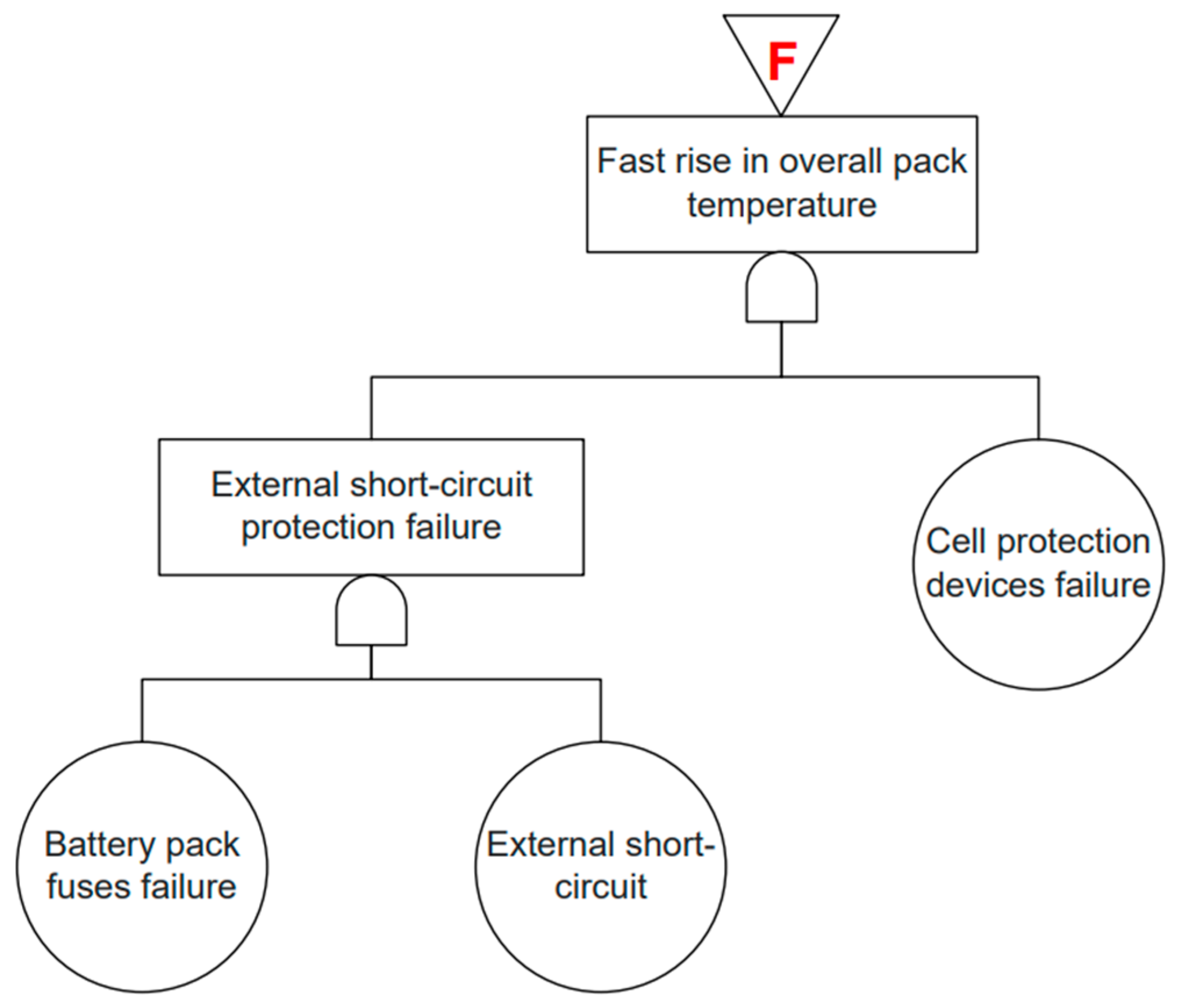
A fast rise in overall pack temperature may occur if an external short-circuit is not properly interrupted. An external short-circuit in the battery pack can generate thousands of amperes, causing an immediate and significant temperature rise due to Joule heating, particularly in the cables and busbars. During normal operation, the battery pack fuses are designed to melt and interrupt the short-circuit. If the fuses fail and the cell protection devices are also defective, the short-circuit can lead to a fast and uncontrolled temperature rise in the overall battery pack. The FTA of a fast rise in overall pack temperature is shown in Figure 9.

3.1.7. Fast Localized Rise Pack Temperature (Branch G)

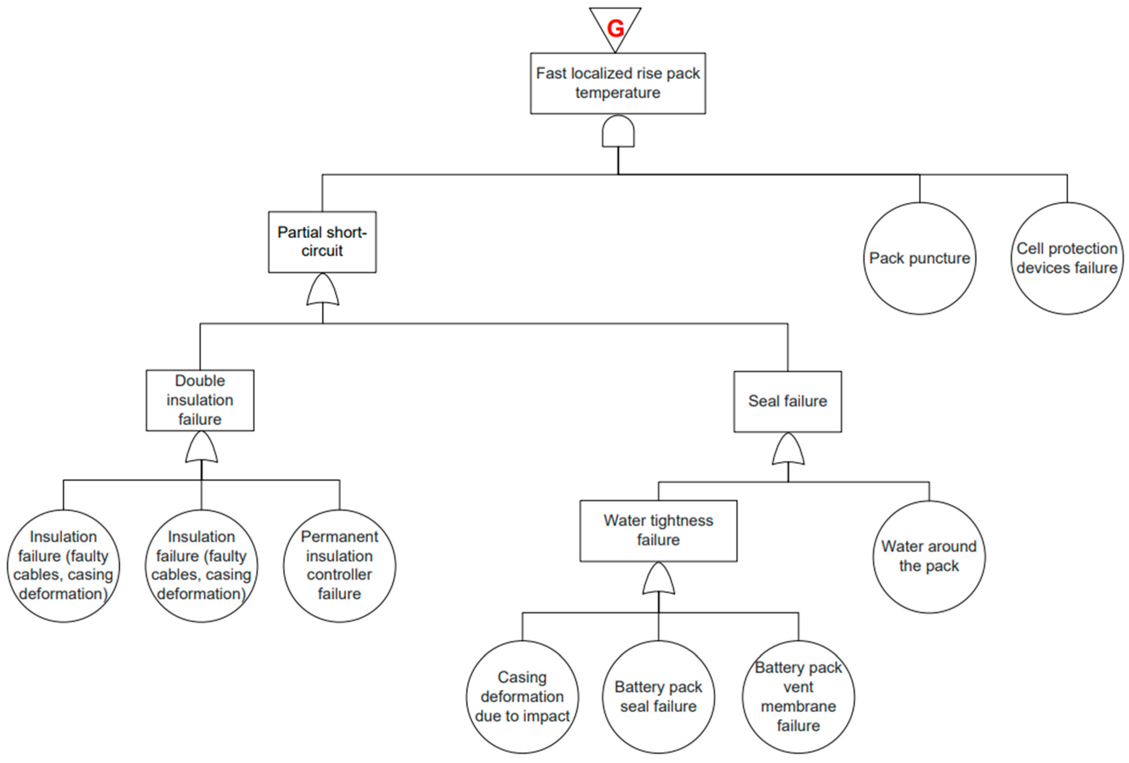
A partial short-circuit may occur when an internal short-circuit develops in a portion of the battery pack. Internal short-circuits can be caused by a double insulation fault, when two insulation defects (such as faulty cables or casing deformation) occur and are not detected by the Permanent Insulation Controller (PIC). They can also result from a sealing defect, for example when water enters into the pack due to a failed seal, a casing deformation or a malfunctioning pack vent membrane. More directly, penetration of the pack by a conductive or non-conductive object can also induce a partial short-circuit by creating direct or indirect contact between two different potentials within the battery pack. Under normal conditions, cell protection devices can prevent excessive local heating; if these protections fail, the partial short-circuit can lead to a fast localized rise in battery pack temperature. The FTA of a fast localized rise pack temperature is shown in Figure 10.

3.1.8. Overcharge (Branch H)

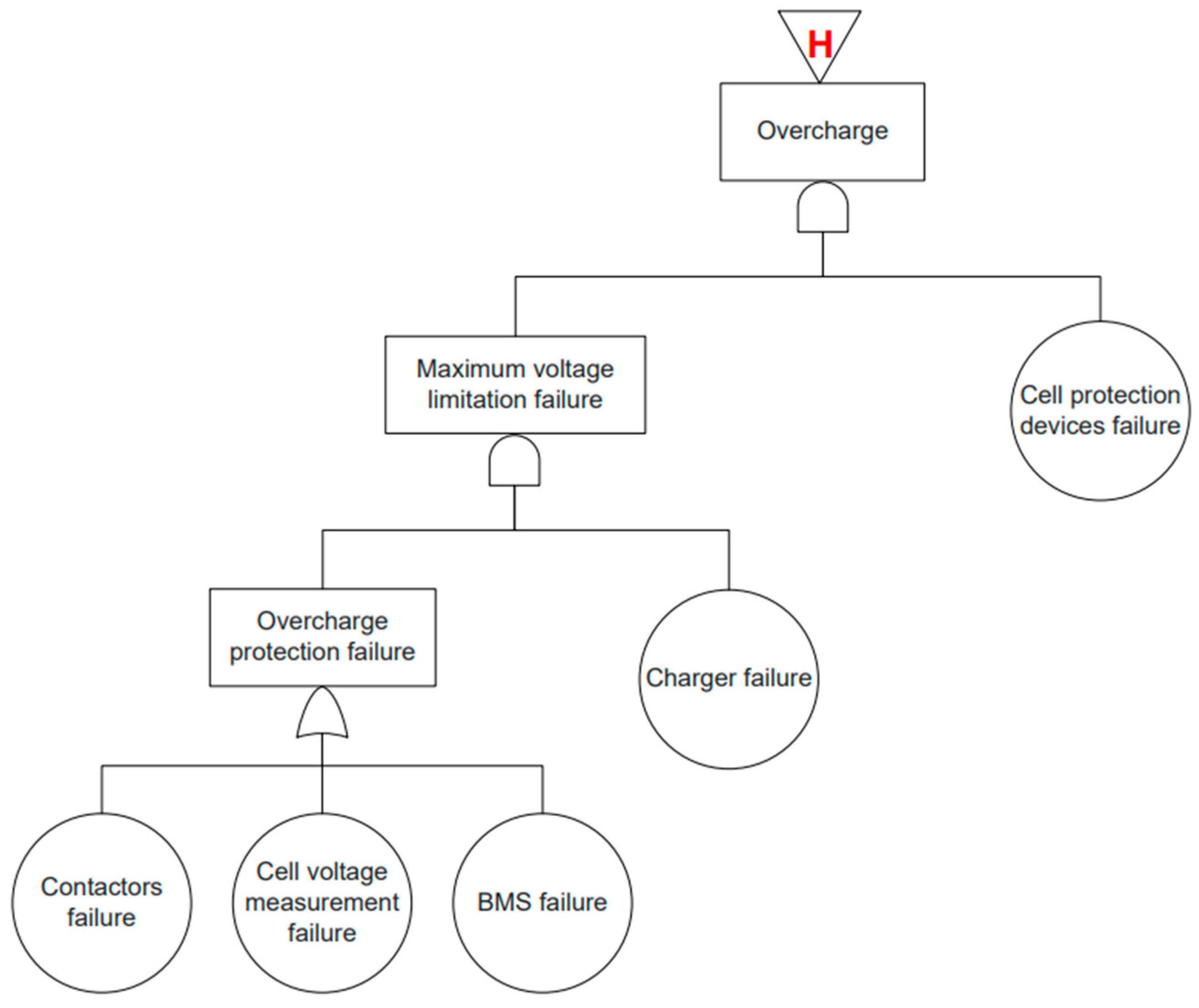
An overcharge may occur if the maximum cell voltage is not properly limited. When cells are overcharged, internal pressure rises, which can trigger the activation (opening) of the cell protection devices. Under normal operating conditions, the charger is limited in the maximum voltage it can deliver and therefore cannot overcharge the battery pack, except in the case of an internal malfunction. In addition, the BMS monitors the cell voltages and can open the contactors to prevent or stop an overcharge condition. The FTA of overcharge is shown in Figure 11.

3.1.9. Ignition in the Battery Pack (Without Thermal Runaway—Branch I)

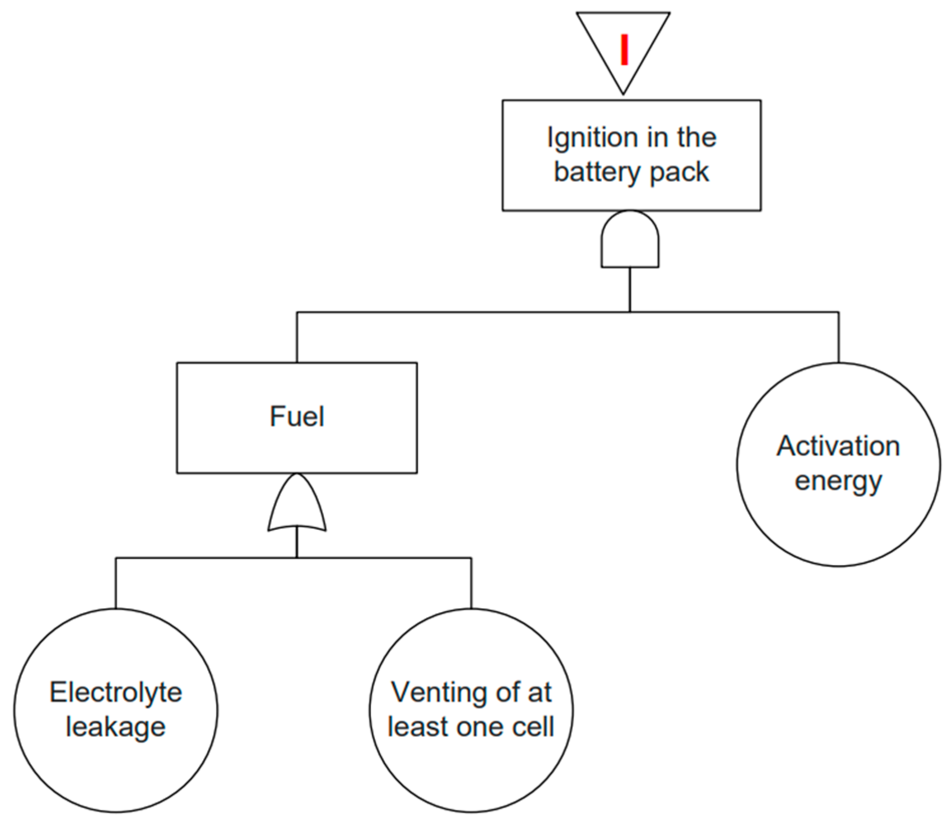
A fire may occur within the battery pack in the event of electrolyte leakage or venting of at least one cell. When this happens, the released compounds act as fuel, and in the presence of an activation source, a fire can start. The resulting fire heats the cells and may ultimately trigger a full battery pack fire. The FTA of ignition in the battery pack is shown in Figure 12.

3.1.10. Explosion (Branch J)

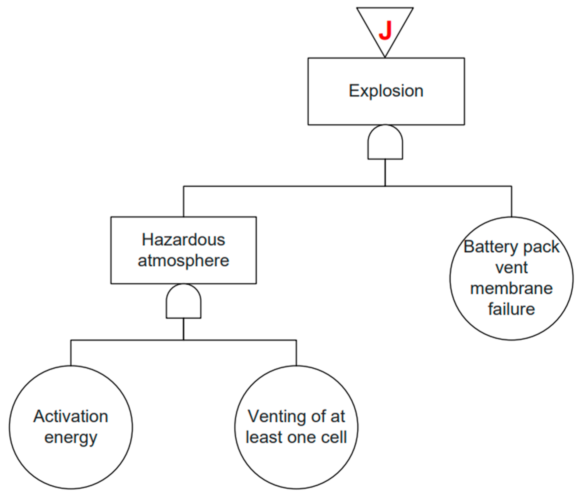
An explosion may occur if a hazardous atmosphere is formed due to the presence of an activation source and the venting of at least one cell. This atmosphere, combined with the failure of the pack vent membrane, can lead to an explosion when the battery pack casing ruptures. The hot gases expelled from the pack may then ignite upon contact with ambient oxygen, potentially resulting in a generalized battery pack fire. The FTA of an explosion is shown in Figure 13.

3.2. Application of the FTA to Use-Case Context Using Probabilities Collected with a Fuzzy Logic Approach and the Literature

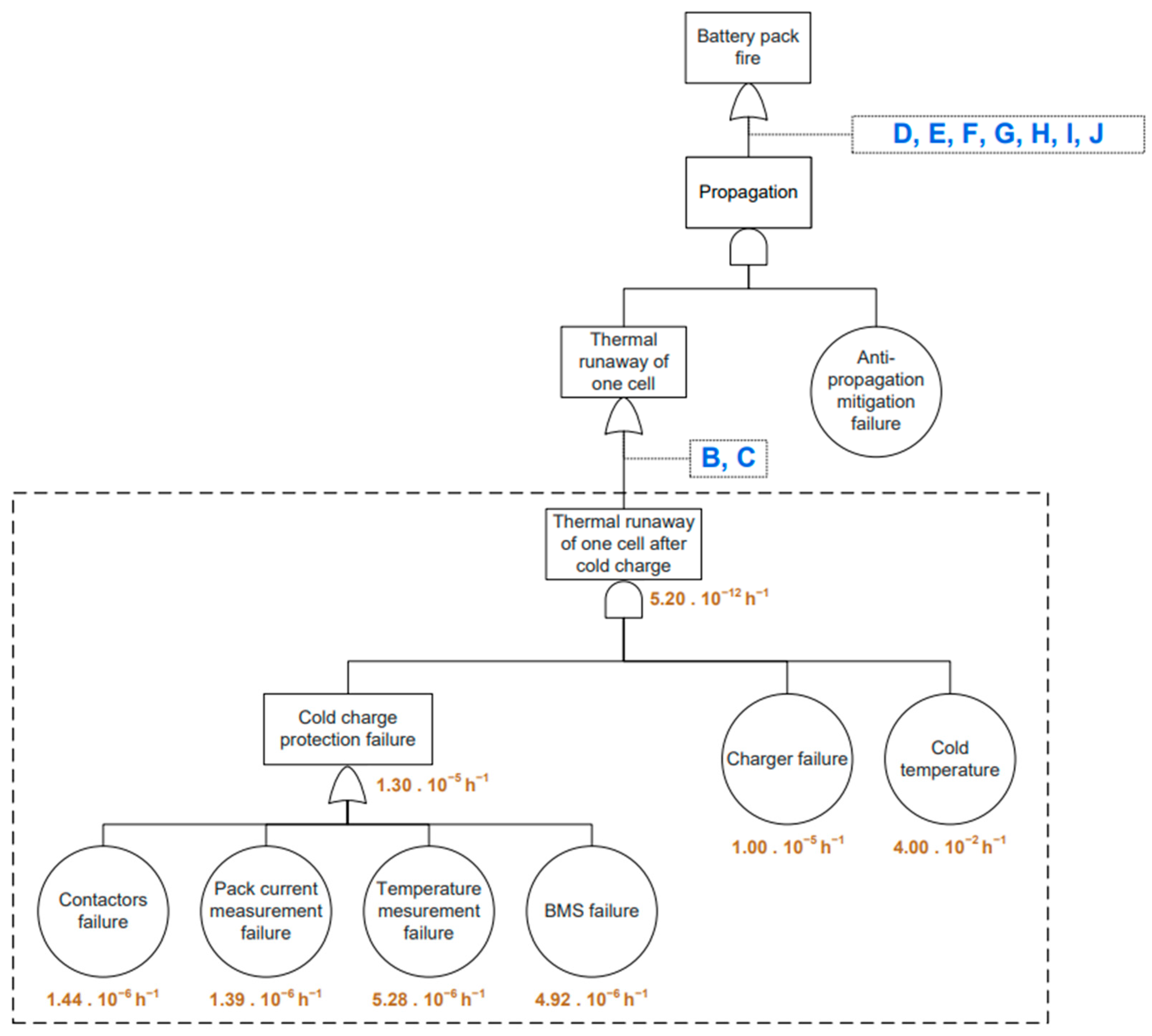
To illustrate the use of the fault tree presented in Section 3.1, a focus on branch A—thermal runaway of one cell after cold charge—is shown in Figure 14. This figure provides an overview of the complete fault tree leading to a battery pack fire, while explicitly developing branch A down to the basic events that may result in the thermal runaway of one cell after cold charge. The probabilities associated with this branch are indicated on the fault tree at both the basic-event level and the intermediate-event level corresponding to branch A. The probabilities associated with this branch are also detailed in Table 2.
The failures related to contactors, current and temperature measurement as well as the BMS were collected using the expert questionnaire and the fuzzy logic approach described in Section 2.2. The charger-related failure corresponds to the electrical failure rate applied to electrical components which is assumed to be 1.00 × 10⁻⁵ h−1, consistent with predictions derived from the MIL-HDBK-217 [20] and FIDES [21] reliability assessment methods. The probability associated with the “cold temperature” failure is highly variable and must be adjusted according to the operating context of the battery pack under study. In this work, the battery pack is assumed to be located in Isère, at Grenoble. A cold condition is defined as an ambient temperature below 0 °C. Based on climatic data over the past 20 years, the average number of hours with temperature below 0 °C in Grenoble is 344 h per year. This corresponds to a probability of 4.00 × 10⁻² h−1. Based on the equations presented in Section 1 and the probabilities listed in Table 2, the probability of the intermediate event “Cold charge protection failure” is estimated to be 1.30 × 10⁻⁵ h−1, while the overall probability associated with branch A—thermal runaway of a cell after cold charge—is 5.20 × 10⁻¹² h−1.
To go further, FTA can be used to study multiple levels of protection against given failure. In very cold climates, battery packs may be equipped with a battery preconditioning system, whose purpose is to heat the battery above 0 °C to protect it from cold charging and potential degradation caused by sub-zero temperatures [22,23]. In this case, the battery preconditioning function can be added to the fault tree, as it represents an additional safety element that help prevents the thermal runaway of one cell after cold charge failure. Assuming a probability of 1.00 × 10⁻⁵ h−1, the preconditioning system reduces the probability of thermal runaway of one cell after cold charge from 5.20 × 10⁻¹² h −1 to 5.20 × 10⁻¹⁷ h−1. Conversely, the absence of protection against cold charging significantly increases the probability of failure, which relies only on the charger and rises to 4.00 × 10⁻⁷ h−1.
FTA can also be used to study the degradation of protection systems over time. For instance, temperature measurement is often performed at only a few points within the battery pack, which can make the estimation of the global temperature inaccurate. In addition, some components involved in temperature sensing, such as thermal paste used to attach temperature sensors, may degrade over time. In such a case, the probability of temperature measurement failure increases, for example up to 5.28 × 10⁻⁴ h−1, which increases the probability of cold charge protection failure to 5.04 × 10⁻⁴ h−1 and the probability of thermal runaway of one cell after cold charge to 2.10 × 10⁻¹⁰ h−1.
Finally, FTA highlights not only the failures most critical to safety but also existing gaps and limitations in current protection systems. In particular, FTA identifies critical components that act as the final barriers before the occurrence of the top event. For example, the anti-propagation mitigation system appears to be a critical safety component for the battery pack because it serves as the final measure to prevent propagation, and providing an effective solution remains a major challenge.

4. Conclusions

This study presents a comprehensive and system-level fault tree for lithium-ion battery pack fire in electric vehicles, which, to the author’s knowledge, has not been previously reported in the open literature in such a global form. By structuring all major failure pathways leading to a battery pack fire, this fault tree provides a common reference for understanding interactions between electrical, thermal, and mechanical failure mechanisms. Made available as open-access material, it represents a valuable tool that can support the design of battery packs and guide future safety-oriented developments. An original aspect of this study is the use of a fuzzy logic-based expert approach to address the lack of probabilistic data for many battery failure modes. By combining information extracted from the literature with the expertise of a large panel of battery specialists, this method enables the estimation of probabilities that would remain inaccessible. The comparison between literature-based data and expert assessments shows a good level of consistency, indicating that expert judgment provides coherent inputs. Beyond the quantified results, the main contribution of this work is methodological. The proposed approach demonstrates how Fault Tree Analysis can be applied to a lithium-ion battery system. The fault tree structure is intentionally generic and adaptable, allowing it to be used, refined or extended for different battery architectures, applications and operating conditions. Future work will focus on refining probability estimates through experimental feedback, reducing uncertainties and using this framework to compare alternative battery designs and safety strategies.

Supplementary Materials

The following supporting information can be downloaded at: https://www.mdpi.com/article/10.3390/batteries12070252/s1.

Author Contributions

Conceptualization, A.D. and C.W.; methodology, A.D.; software, A.D.; validation, J.D., R.V., C.W., D.G., C.P. and C.B.; formal analysis, A.D., J.D., R.V., C.W. and D.G.; investigation, A.D.; resources, C.B.; data curation, A.D.; writing—original draft preparation, A.D.; writing—review and editing, J.D., R.V., C.W., D.G., C.P. and C.B.; visualization, A.D.; supervision, C.W.; project administration, C.B. and C.P. All authors have read and agreed to the published version of the manuscript.

Funding

This research received no external funding.

Data Availability Statement

The data presented in this study are available on request from the corresponding author.

Conflicts of Interest

The authors declare no conflict of interest.

References

  1. Sahoo, M.; Kaushik, S.; Gupta, M.; Islam, M.K. EVs and renewables: Navigating future sustainability with symmetry and asymmetry. Transp. Res. D Transp. Environ. 2024, 132, 104233. [Google Scholar] [CrossRef]
  2. Ngoy, K.R.; Lukong, V.T.; Yoro, K.O.; Makambo, J.B.; Chukwuati, N.C.; Ibegbulam, C.; Eterigho-Ikelegbe, O.; Ukoba, K.; Jen, T.-C. Lithium-ion batteries and the future of sustainable energy: A comprehensive review. Renew. Sustain. Energy Rev. 2025, 223, 115971. [Google Scholar] [CrossRef]
  3. Joshi, A.; Saini, S.; Chand, P. Li-ion batteries for energy storage. In Low-Dimensional Multifunctional Hybrid Nanostructured Materials: Energy and Environmental Applications; Sonker, R.K., Singh, K., Sonkawade, R., Eds.; Springer Nature: Berlin/Heidelberg, Germany, 2025; pp. 77–101. [Google Scholar] [CrossRef]
  4. Li, J.; Du, Z.; Ruther, R.E.; Jin AN, S.; David, L.A.; Hays, K.; Wood, M.; Phillip, N.D.; Sheng, Y.; Mao, C.; et al. Toward lowcost, high-energy density, and high-power density lithium-ion batteries. JOM 2017, 69, 1484–1496. [Google Scholar] [CrossRef]
  5. Zhu, G.-L.; Zhao, C.-Z.; Huang, J.-Q.; He, C.; Zhang, J.; Chen, S.; Xu, L.; Yuan, H.; Zhang, Q. Fast charging lithium batteries: Recent progress and future prospects. Small 2019, 15, 1805389. [Google Scholar] [CrossRef] [PubMed]
  6. Zentani, A.; Almaktoof, A.; Kahn, M.T. A comprehensive review of developments in electric vehicles fast charging technology. Appl. Sci. 2024, 14, 4728. [Google Scholar] [CrossRef]
  7. IEA. Trends in Electric Car Markets—Global EV Outlook 2025—Analysis, IEA. Available online: https://www.iea.org/reports/global-ev-outlook-2025 (accessed on 16 January 2026).
  8. Aalund, R.; Diao, W.; Kong, L.; Pecht, M. Understanding the non-collision related battery safety risks in electric vehicles a case study in electric vehicle recalls and the LG chem battery. IEEE Access 2021, 9, 89527–89532. [Google Scholar] [CrossRef]
  9. Tong, L.; Wu, S.; Luan, W.; Chen, H. Impact of temperature-dependent aging on overcharge-induced thermal runaway in lithium-ion batteries. J. Power Sources 2025, 652, 237466. [Google Scholar] [CrossRef]
  10. Zhao, Y.; Wang, Z.; Yan, L.; Sun, Z.; Liu, P.; Zhang, L.; Li, W. Bridging battery degradation and safety: Challenges and opportunities. eTransportation 2025, 26, 100497. [Google Scholar] [CrossRef]
  11. Huang, Y.; Zhao, Y.; Bai, W.; Cao, Y.; Xu, W.; Shen, X.; Wang, Z. Study on the influence of high rate charge and discharge on thermal runaway behavior of lithium-ion battery. Process Saf. Environ. Prot. 2024, 191, 1483–1494. [Google Scholar] [CrossRef]
  12. Gong, C.; Liu, J.; Han, Y.; Hu, Y.; Yu, H.; Zeng, R. Safety of electric vehicles in crash conditions: A review of hazards to occupants, regulatory activities, and technical support. IEEE Trans. Transp. Electrif. 2022, 8, 3870–3883. [Google Scholar] [CrossRef]
  13. Gravante, E.; D’Arpino, M. FMEA-graph-based approach for the identification of critical cascading failure events in li-ion battery packs. In Proceedings of the 2025 IEEE/AIAA Transportation Electrification Conference and Electric Aircraft Technologies Symposium (ITEC+EATS), Anaheim, CA, USA, 18-20 June 2025; IEEE: Piscataway, NJ, USA, 2025. [Google Scholar] [CrossRef]
  14. Chauhan, N.; Yang, S.; Thiede, S. Risk assessment of retired lithium-ion battery packs: FMEA and pugh matrix integration. Procedia CIRP 2025, 135, 1320–1325. [Google Scholar] [CrossRef]
  15. Jiang, H.; Lin, C.; Feng, G.; Xu, E.; Zheng, W. Reliability analysis of the highvoltage power battery system based on the polymorphic fuzzy fault tree. J. Sens. 2022, 2022, 2455345. [Google Scholar] [CrossRef]
  16. Hu, G.; Huang, P.; Bai, Z.; Wang, Q.; Qi, K. Comprehensively analysis the failure evolution and safety evaluation of automotive lithium ion battery. eTransportation 2021, 10, 100140. [Google Scholar] [CrossRef]
  17. Signoret, J.-P. Arbre de défaillance Contexte booléen, analyse et bases mathématiques. In Techniques de l’Ingénieur Sécurité et Gestion des Risques Base Documentaire: TIP112WEB; Ref. se4052; Editions Techniques de l’Ingénieur: Paris, France, 2017; Available online: https://www.techniques-ingenieur.fr/base-documentaire/environne-ment-securite-th5/methodes-d-analyse-des-risques-42155210/arbr e-de-defaillance-se4052/ (accessed on 20 January 2026). [CrossRef]
  18. Feng, X.; Ouyang, M.; Liu, X.; Lu, L.; Xia, Y.; He, X. Thermal runaway mechanism of lithium ion battery for electric vehicles: A review. Energy Storage Mater. 2018, 10, 246–267. [Google Scholar] [CrossRef]
  19. Misiani, A.N.; Oni, B.A. A review on challenges in low temperature Lithiumion cells and future prospects. Appl. Energy 2025, 393, 125987. [Google Scholar] [CrossRef]
  20. U.S. Department of Defense. MIL-HDBK-217F: Reliability Prediction of Electronic Equipment; Notice 2; U.S. Department of Defense: Washington, DC, USA, 1995.
  21. FIDES Working Group. FIDES Guide 2016: Reliability Methodology for Electronic Systems; FIDES: Paris, France, 2016. [Google Scholar]
  22. Ilies, A.I.; Jánó, R.; Fodor, A. Battery Preconditioning Methods for Electric Vehicles in Cold Climates: A Comparative Review. In Proceedings of the 2025 International Spring Seminar on Electronics Technology (ISSE), Budapest, Hungary, 14–18 May 2025; pp. 1–7, ISSN 2161-2536. [Google Scholar] [CrossRef]
  23. Ilies, A.-I.; Jánó, R. Optimizing Li-Ion Battery Preconditioning Strategies for Electric Vehicles in Cold Climates Using Thin Film and Internal Heating Approaches. In Smart Solutions in Power Engineering, Robotics and Human Centered Systems; Zielinska, T., Ed.; Springer Nature: Cham, Switzerland, 2026; pp. 129–138. [Google Scholar] [CrossRef]
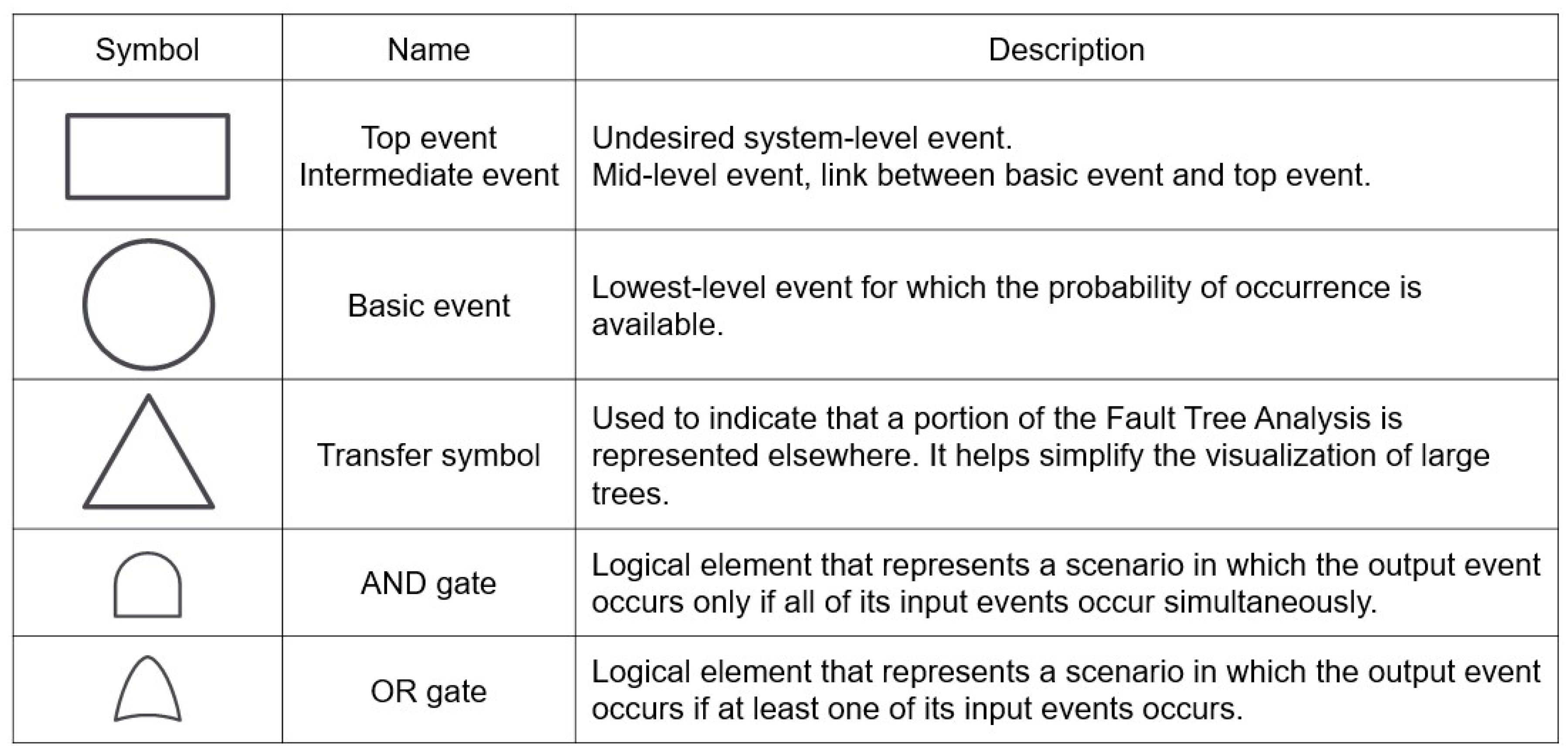
Figure 1. Representation of the elements constituting a Fault Tree Analysis (FTA).
Batteries 12 00252 g001
Figure 2. Schematic of the use-case battery pack sent to the experts with the questionnaire.
Batteries 12 00252 g002
Figure 3. Global FTA of a lithium-ion battery pack for the identified use-case.
Batteries 12 00252 g003
Figure 4. FTA of branch A—thermal runaway of one cell after cold charge.
Batteries 12 00252 g004
Figure 5. FTA of branch B—charge after over-discharge.
Batteries 12 00252 g005
Figure 6. FTA of branch C—local overheating.
Batteries 12 00252 g006
Figure 7. FTA of branch D—pack global overheating.
Batteries 12 00252 g007
Figure 8. FTA of branch E—progressive rise in overall pack temperature.
Batteries 12 00252 g008
Figure 9. FTA of branch F—fast rise in overall pack temperature.
Batteries 12 00252 g009
Figure 10. FTA of branch G—fast localized rise in pack temperature.
Batteries 12 00252 g010
Figure 11. FTA of branch H—overcharge.
Batteries 12 00252 g011
Figure 12. FTA of branch I—ignition in the battery pack.
Batteries 12 00252 g012
Figure 13. FTA of branch J—explosion.
Batteries 12 00252 g013
Figure 14. Detailed FTA of branch A—thermal runaway of one cell after cold charge.
Batteries 12 00252 g014
Table 1. Quantification of qualitative responses into probabilities for FTA evaluation.
ResponseAssociated Probability
Very likely 1 × 10⁻⁴ h−1
Likely 1 × 10⁻⁶ h−1
Unlikely 1 × 10⁻⁸ h−1
Very unlikely 1 × 10⁻¹⁰ h−1
Unknown
Table 2. Detailed probabilities related to branch A—thermal runaway of one cell after cold charge.
FailureAssociated Probability
Contactor failure1.44 × 10−6 h−1
Pack current measurement failure1.39 × 10−6 h−1
Temperature measurement failure5.28 × 10−6 h−1
BMS failure4.92 × 10−6 h−1
Charger failure1.00 × 10−5 h−1
Cold temperature4.00 × 10−2 h−1
Disclaimer/Publisher’s Note: The statements, opinions and data contained in all publications are solely those of the individual author(s) and contributor(s) and not of MDPI and/or the editor(s). MDPI and/or the editor(s) disclaim responsibility for any injury to people or property resulting from any ideas, methods, instructions or products referred to in the content.