1. Introduction
Lithium-ion batteries are designed to operate within specified temperature, voltage, and current ranges defined by manufacturer datasheets. Operating batteries beyond these rated specifications can result in battery failure and potentially lead to hazardous events such as thermal runaway [
1]. Under manufacturer-specified operating limits, lithium-ion batteries’ capacity gradually degrades over time due to electrochemical side reactions, mechanical stress, and material aging. Repeatedly cycling a lithium-ion battery at its maximum capacity and at other manufacturer limits can accelerate degradation mechanisms, resulting in a shortened life.
To satisfy lifetime requirements, battery systems are often designed to operate below manufacturer-specified limits. Derating may include reducing usable capacity, limiting charge/discharge current, narrowing voltage windows, or restricting operating temperature ranges. In practice, various “generic” derating guidelines or recommendations have been adopted across industries to establish operational limits for temperature, voltage, current, and non-rated parameters, such as state of charge (SOC). However, these approaches do not quantify the extent to which battery lifetime is extended under specific operating conditions. As a result, derating decisions are often based on engineering judgment rather than quantitative analysis.
In electric vehicle applications, manufacturers such as Tesla, BYD, and MG Motors [
2,
3,
4] recommend avoiding frequent charging to full SOC for daily use, minimizing prolonged periods at high SOC (e.g., 100%), reducing charging current or driving power under high or low temperature conditions, limiting repeated fast charging events, and preconditioning the battery before high-power operation in cold environments. Similar recommendations are provided for consumer electronics [
5], including limiting continuous charging, reducing deep-discharge cycles, and minimizing high-power usage during charging. Long-term storage guidance typically recommends maintaining a SOC below 100% and avoiding extreme temperatures.
Derating strategies have been studied from static and dynamic perspectives (see Ruan et al. [
6]). Static approaches rely on predefined operational limits, whereas dynamic strategies leverage real-time data, degradation estimates, and predictive modeling to continuously adjust derating parameters based on system conditions.
Barreras et al. [
7] reviewed derating methods for electric vehicle applications and analyzed the influence of temperature, SOC, current (C-rate), and voltage on battery safety and lifespan. They demonstrated the individual impact of these parameters through simulations and how derating can enhance battery safety.
Sun et al. [
8] introduced a method based on capacity-loss data to evaluate derating for LCO and LFP batteries, using a derating factor to represent the relationship between aging severity and operating parameters. They concluded that temperature is the most significant derating parameter to reduce the rate of capacity loss.
Schimpe et al. [
9] developed a degradation-aware electrical current derating method in which calendar and cycle aging are evaluated across a range of temperature, state of charge, and current conditions, and the resulting degradation rates are embedded into online control through lookup tables. During operation, the charge and discharge currents are dynamically adjusted to constrain the degradation rate below the predefined thresholds, thereby trading short-term power for extended lifetime. Simulation studies of residential battery energy storage systems (BESSs) have demonstrated that this method can increase the battery lifetime by 65% and total lifetime energy throughput by 49%, while reducing the annual energy throughput by 9.5%.
Sowe et al. [
10] combined semi-empirical degradation models with techno-economic optimization to extend battery life in mini-grid systems. A SOC- and temperature-based current derating method was applied, and they suggested that the battery life could be extended by 45% (or 6–7 years) with minimal impact on system performance.
Rajah et al. [
11] applied degradation-aware electrical current derating to large-scale lithium-ion battery energy storage systems. They concluded that dynamically derating charge and discharge currents could extend the battery’s lifetime by approximately 5–8 years.
Although these studies demonstrate the effectiveness of derating strategies, and the approaches are primarily developed from modeling or system-level optimization perspectives, a practical battery derating guideline for design-stage decision-making is still missing: one that clearly specifies (1) the specified rated limits, (2) the degradation data required, and (3) how key rated limits from battery datasheets (e.g., maximum voltage, current, and operating temperature) can be converted into quantitative derating levels (e.g., percentage or magnitude of stress reductions and life improvements).
The developed methodology shares the general objective of traditional electronic-component derating approaches, such as safe operating area (SOA) methods [
12] and reliability guidelines for power electronics (e.g., MIL-HDBK-1547A) [
13], which aim to improve reliability by operating components below their rated limits. However, lithium-ion batteries uniquely degrade through capacity loss and resistance growth, and their aging behavior depends strongly on operating conditions, including state of charge, temperature, voltage, and current [
14]. Therefore, battery derating requires the consideration of degradation data and lifetime objectives in addition to rated operating limits. The developed work therefore extends the concept of derating from conventional reliability-margin practices to battery-specific degradation management by linking datasheet-rated limits, degradation data, and target lifetime requirements.
During early-stage product design or battery selection, engineers rely on manufacturer datasheets and limited capacity-loss test data when determining appropriate operational limits. Therefore, an approach for utilizing datasheet-rated parameters and degradation data to generate quantitative derating recommendations is needed. The developed approach is primarily intended for system-level engineers, battery-pack designers, battery management system (BMS) developers, and product designers who must establish operational limits during battery selection and early-stage system design using manufacturer datasheets and limited degradation data.
This paper presents a quantitative derating method that integrates datasheet-rated parameter limits, degradation data inputs, analysis procedures, and target performance outcomes to estimate appropriate derating margins. The expected life improvements are quantified, enabling tailored derating strategies for different batteries and applications.
Section 2 discusses manufacturer datasheets and key rated parameters that influence battery performance.
Section 3 presents the developed derating approach. Finally, an application example of derating is presented in
Section 4.
2. Manufacturer Datasheets and Rated Parameters Relevant to Derating
Manufacturer datasheets are the primary source of information for battery selection and system integration. The datasheet includes rated information about the battery’s electrical, mechanical, and thermal characteristics. It offers performance information under various conditions, including different charge/discharge rates, temperatures, and charge-discharge cycles [
15].
Datasheets provide safety guidelines, including maximum allowable voltages, currents, and temperatures, to prevent overcharging, overheating, and thermal runaway. In addition, datasheets may include performance curves and technical specifications that support application-specific design decisions. They may also include industry certifications, compliance standards, and best practices for charging, discharging, and storage to help extend battery life.
For design-stage decision-making, the rated parameters in the datasheet represent the operating boundaries from which derating margins can be established. Typically, the recommended charging method is constant current–constant voltage (CC/CV), where the battery is charged at a constant current until a maximum charge voltage is reached, then held at that voltage until the current reduces to a fixed level. Discharging is typically achieved by maintaining a constant current until a specified cutoff voltage is reached.
A rated value, as defined by the IEC dictionary [
16], is the “value of a quantity used for specification purposes, established for a specified set of operating conditions of a component, device, equipment, or system”. The maximum-rated value is the highest value of that rated parameter.
Typical rated parameters listed in lithium-ion battery datasheets include energy (or capacity), nominal voltage, charge current, charge voltage, charge cutoff current, maximum charge voltage, maximum charge current, discharge current, discharge cutoff voltage, maximum discharge current, operating temperature during charge and discharge, and storage temperature.
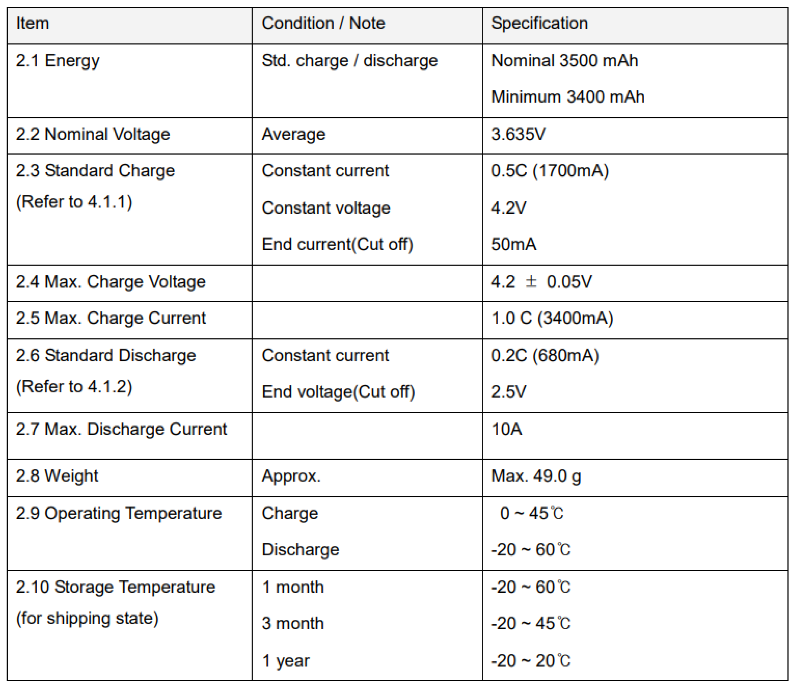
Figure 1 provides an example of the datasheet specifications for a lithium-ion INR18650 MJ1 battery [
17]. For this work, rated limits refer to the manufacturer-specified operating limits (e.g., maximum charge voltage, maximum current, and operating temperature range) rather than nominal or typical performance values, as these limits define the approved operating boundaries of the battery and provide the baseline reference conditions from which quantitative derating margins are established.
Operation within datasheet limits maintains the battery within manufacturer-defined safe operating conditions. However, operating within these limits does not eliminate battery degradation, and datasheets typically do not specify the expected lifetime (e.g., cycle life to a certain capacity loss) under all operating conditions. Exceeding the rated ranges can accelerate degradation and introduce potential safety risks, including overheating, internal short circuits, and thermal runaway. Battery derating is therefore introduced as a practical approach to mitigate both safety and reliability concerns by intentionally operating the battery below certain rated limits. Safety-oriented derating aims to maintain a sufficient margin from conditions that could lead to hazardous failures, such as thermal runaway, venting, or internal short circuits. In contrast, reliability-oriented derating seeks to reduce degradation mechanisms, such as SEI growth, lithium plating, electrolyte decomposition, and capacity loss, thereby extending the battery lifetime. The derating approach presented in this work improves reliability and battery life while maintaining operation within manufacturer-specified safety limits.
The effectiveness of derating depends on the selection of derating rate parameters, the derated values, and the battery usage case. Based on battery datasheets, the key rated parameters to consider are energy (capacity), current (C-rate), voltage, and temperature. The following subsections discuss how each rated parameter is linked to battery degradation and how it can be used as a basis for quantitative derating.
2.1. Battery Capacity and State of Charge
Datasheets specify nominal capacity and minimum capacity under defined test conditions, typically expressed in ampere-hours (Ah) or milliampere-hours (mAh). Nominal capacity represents the total charge the battery can deliver under standard test conditions when operated across the full rated voltage window.
While the existing recommendations in industry applications use state of charge (SOC) as a derating parameter, it is not a rated parameter in a datasheet. SOC defines how much of the rated capacity is available at a specified time. Operating near extreme SOC levels (close to 0% or 100%) increases the risk of electrolyte oxidation and transition metal dissolution, while deep discharge can destabilize electrode structures [
18,
19,
20].
Derating capacity can therefore be achieved by reducing the total usable capacity specified at the system design level or by limiting the allowable SOC during operation. For example, limiting operations to 20–80% SOC instead of the full 0–100% range is a form of operational capacity derating, as it reduces the portion of the rated capacity actually accessed in practice. Since nominal capacity is specified in the datasheet, the derated usable capacity can be expressed directly as a fraction of the rated value, establishing a quantitative link between the datasheet capacity and derating margin. Additionally, SOC control prevents the battery from remaining fully charged or fully discharged.
2.2. Voltage Limits
Lithium-ion batteries are designed with voltage limits, which represent the voltage range at which the battery can safely operate. Voltage limits play a critical role in determining a battery’s capacity. Operating a battery within its recommended voltage range prevents overcharging and overdischarging, which may reduce its lifespan. Overcharge increases the risk of thermal runaway by triggering electrolyte decomposition and gas generation [
21,
22], and overdischarge can lead to irreversible chemical changes, such as electrolyte degradation and electrode instability [
23]. Therefore, voltage regulation is a key component of derating strategies for ensuring safe and reliable battery operation.
Voltage thresholds should be set based on the manufacturer’s rated values, and battery management systems should be implemented to monitor and control voltage levels throughout charge–discharge cycles. During charging, exceeding the maximum voltage can cause electrolyte decomposition, especially at the cathode, generating gases that increase internal pressure and the risk of leakage [
24]. Charging above the maximum voltage may also trigger exothermic reactions, leading to rises in temperature and internal pressure, and potentially resulting in thermal runaway. During discharge, allowing the voltage to drop below the cutoff voltage can cause copper dissolution from the anode current collector. Kasnatscheew et al. [
25] recommended adopting a defined minimum discharge cutoff voltage to reduce the risk of copper dissolution.
The influence of upper cutoff voltage on capacity loss has been experimentally demonstrated by Harlow et al. [
26], who evaluated reconstructed NCA-based coin cells cycled under different voltage windows. Their results showed that reducing the upper cutoff voltage from 4.2 V to 4.0 V could mitigate cycling-induced degradation. After 800 cycles, cells cycled between 3.0–4.0 V exhibited approximately 4–5% capacity loss, whereas cells cycled between 3.0–4.2 V experienced approximately 12% capacity loss.
2.3. Current and C-Rate Limits
C-rate is the ratio of applied current to a battery’s capacity based on one hour of constant operation, as shown in the equation below. For example, a 1C rate means that the battery is charged or discharged at a current equal to its nominal capacity in one hour, while a 2C rate doubles that current for half an hour. In the lithium-ion battery datasheet presented in
Figure 1, the maximum charge current limit is 3.4 A (1C), and the maximum discharge current limit is 10 A (~2.94C) for a 3.4 Ah cell. Both current and C-rate limits are associated with battery cycling and operating conditions. Excessive charging and discharging currents can lead to adverse effects, including increased heat generation, accelerated degradation, and safety hazards.
Current limits are specified in battery datasheets based on maximum charging and discharging currents, and sometimes the peak current for short durations. Cycling and operating the battery within these limits are critical to ensuring safe and efficient operation. During charging, exceeding the recommended current or C-rate can increase internal heat generation [
23]. This heat can accelerate electrolyte decomposition and electrode degradation [
27]. It can also cause an uneven distribution of lithium ions within the electrode materials, leading to localized stress, damage over time, and lithium plating [
28].
During discharge, exceeding the maximum discharge current can lead to similar adverse effects. High discharge currents accelerate the degradation of electrode materials, particularly the cathode, by inducing mechanical stress and phase transitions in the active material [
29,
30]. Excessive discharge currents can also cause voltage drops that push the cell below its cutoff voltage, leading to copper dissolution from the anode current collector [
31,
32]. During subsequent cycling, dissolved copper may redeposit unevenly on electrode surfaces, creating localized current-density concentrations that can promote lithium plating. The resulting lithium deposits may evolve into dendritic structures, increasing the risk of internal short circuits and capacity loss [
33]. Chen [
34] tested LFP prismatic cells at discharge rates between 0.2C and 3C and observed that battery capacity decreases as a function of discharge rate. Saxena [
35] also concluded that a higher C-rate decreases the discharge capacity during cycling.
2.4. Temperature Limits
In lithium-ion battery datasheets, manufacturers specify operating temperature ranges for both charging and discharging, as well as storage temperature limits for both short-term and long-term conditions, including during shipping. Elevated temperatures accelerate both chemical and electrochemical degradation mechanisms during charge and discharge.
During charging, the increase in temperature can accelerate electrolyte decomposition [
36], thereby degrading both the cathode and anode materials through structural breakdown. During battery discharge, increasing temperature generally reduces the internal resistance due to enhanced ionic conductivity and faster electrochemical reaction kinetics. However, sustained operation at elevated temperatures accelerates degradation processes within the battery. Over time, these degradation mechanisms can result in a permanent increase in internal resistance and contribute to capacity loss. In extreme cases, exceeding the rated maximum temperature may initiate exothermic reactions inside the battery, triggering self-heating and potentially leading to thermal runaway [
37].
At temperatures below room temperature, batteries may experience increased internal resistance and higher electrolyte viscosity, both of which reduce ionic conductivity and capacity [
38,
39]. At low temperatures, reduced lithium-ion diffusion and slower charge-transfer kinetics hinder lithium intercalation into the graphite anode [
40]. As a result, lithium may deposit on the anode surface during charging rather than being intercalated into the active material. During discharging, sluggish ion transport and decreased kinetics further impair capacity [
41,
42].
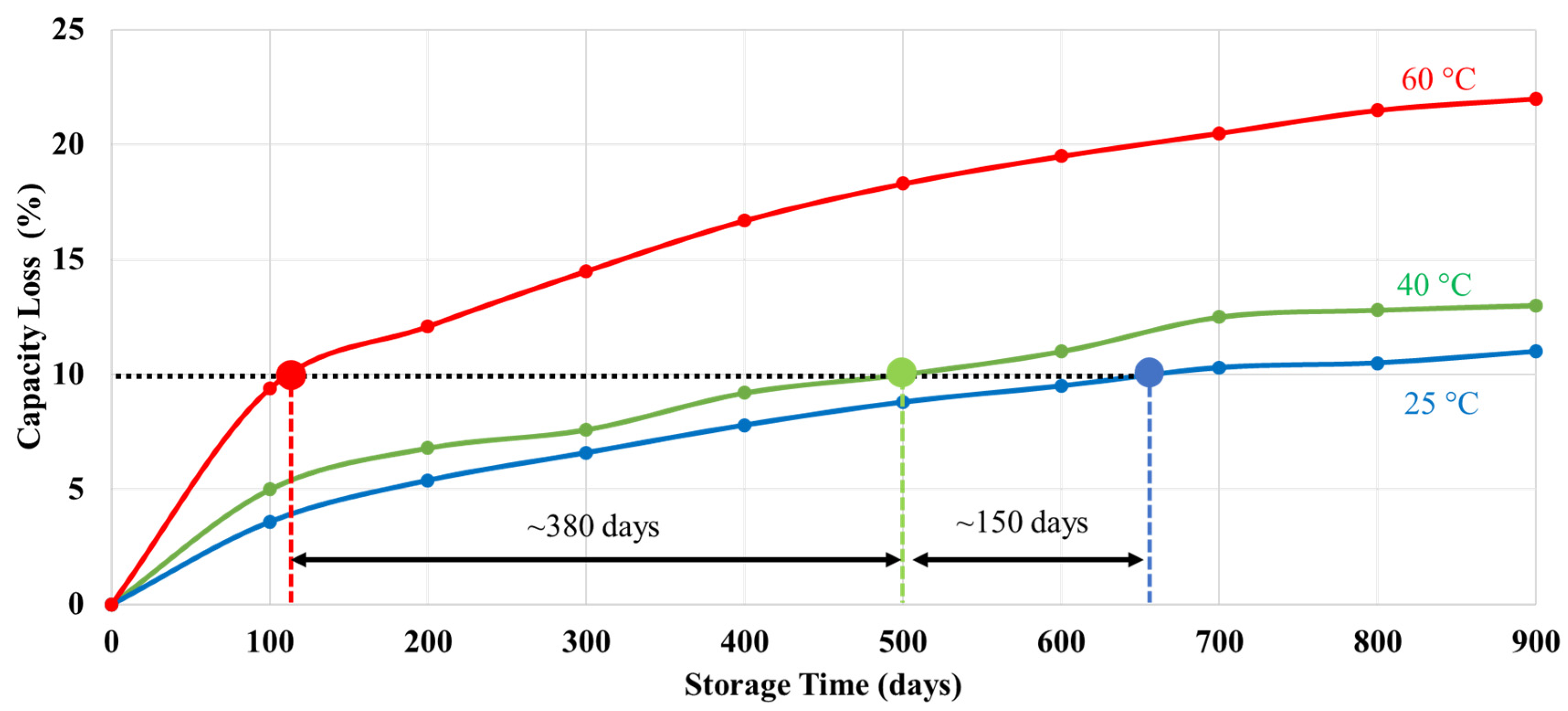
Figure 2 illustrates the effect of storage temperature on capacity loss for a lithium iron phosphate (LFP) pouch cell with a nominal capacity of 3 Ah and a rated maximum temperature of 60 °C. The batteries were stored at 100% SOC, and the data were extracted from [
43]. The results show that higher storage temperatures significantly accelerate capacity loss. For example, lowering the storage temperature from 60 °C to 40 °C extends the time required to reach 10% capacity loss by approximately 380 days, while a further reduction from 40 °C to 25 °C extends this time by an additional 150 days.
2.5. Interactions of Voltage, Current, and Temperature on Battery Degradation
Although capacity, voltage, current (C-rate), and temperature are discussed separately in the above sections, these parameters interact and jointly influence lithium-ion battery degradation [
44,
45]. In practical applications, battery aging is governed by coupled electrochemical, thermal, and mechanical processes rather than by a single stress factor [
46,
47]. For example, operating at a high state of charge or elevated voltage increases the likelihood of electrolyte oxidation and transition-metal dissolution, while elevated temperatures accelerate the kinetics of these degradation reactions. As a result, the combined effect of high voltage and high temperature produces greater degradation than either stress factor alone [
48].
The influence of current is strongly coupled with temperature [
49]. High charge and discharge currents increase internal heat generation through Joule heating, resulting in higher cell temperatures and accelerated degradation. Under low-temperature charging conditions, high charging currents can promote lithium plating due to reduced lithium-ion diffusion rates and slower intercalation kinetics. The plated lithium may subsequently form dendritic structures, increasing the risk of internal short circuits and capacity loss. Therefore, the degradation associated with current loading depends not only on the magnitude of the applied current, but also on the battery temperature and operating voltage window limits [
50].
The developed derating approach evaluates each rated parameter individually based on the available degradation data and datasheet-rated limits. When degradation data are available for multiple stress factors simultaneously, the same methodology can be extended to evaluate combined derating strategies, and the coupled effects are reflected in the degradation data used as inputs. However, the present approach does not model synergistic degradation mechanisms through a coupled electrochemical-aging model.
For design-stage decision-making, the recommended practice is to consider voltage, current, and temperature together when selecting derating margins, particularly under severe operating conditions where coupled degradation mechanisms are expected to dominate battery aging. When multiple derating options are available, priority should generally be given to the parameter that produces the greatest reduction in degradation for the intended application. In many lithium-ion battery studies, temperature and voltage (or SOC) have a greater influence on long-term degradation than current under normal operating conditions [
51]. However, from a system-control perspective, voltage and current limits are often easier to implement through battery management systems, whereas temperature control may require additional thermal-management systems. Therefore, the final derating strategy should consider both the effectiveness of degradation and the feasibility of implementation.
3. Derating Approach for Lithium-Ion Batteries
Derating is based on the rated parameters specified in a battery’s datasheet and their known impacts on performance and degradation. The inputs, analysis methods, and outputs are discussed below.
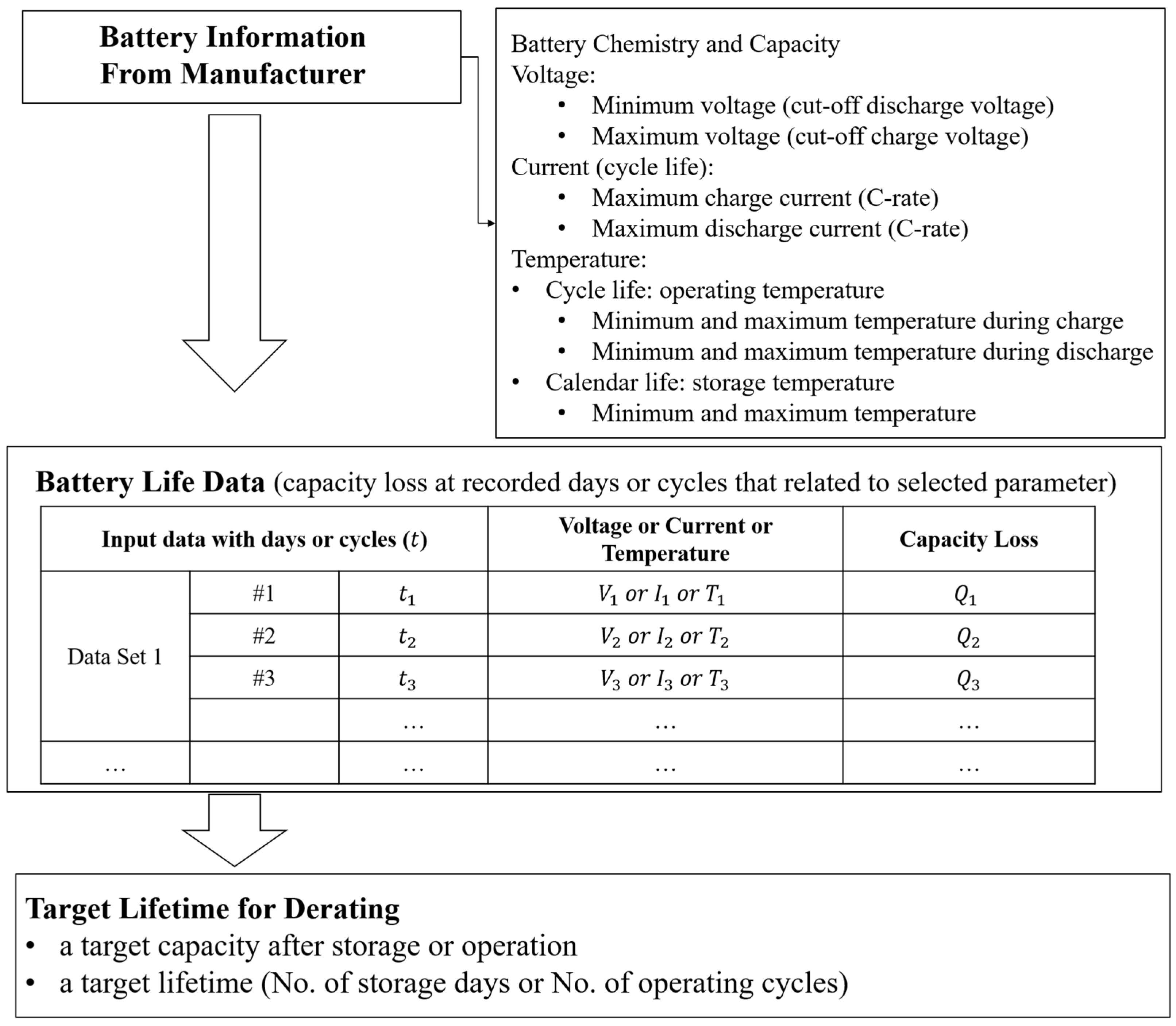
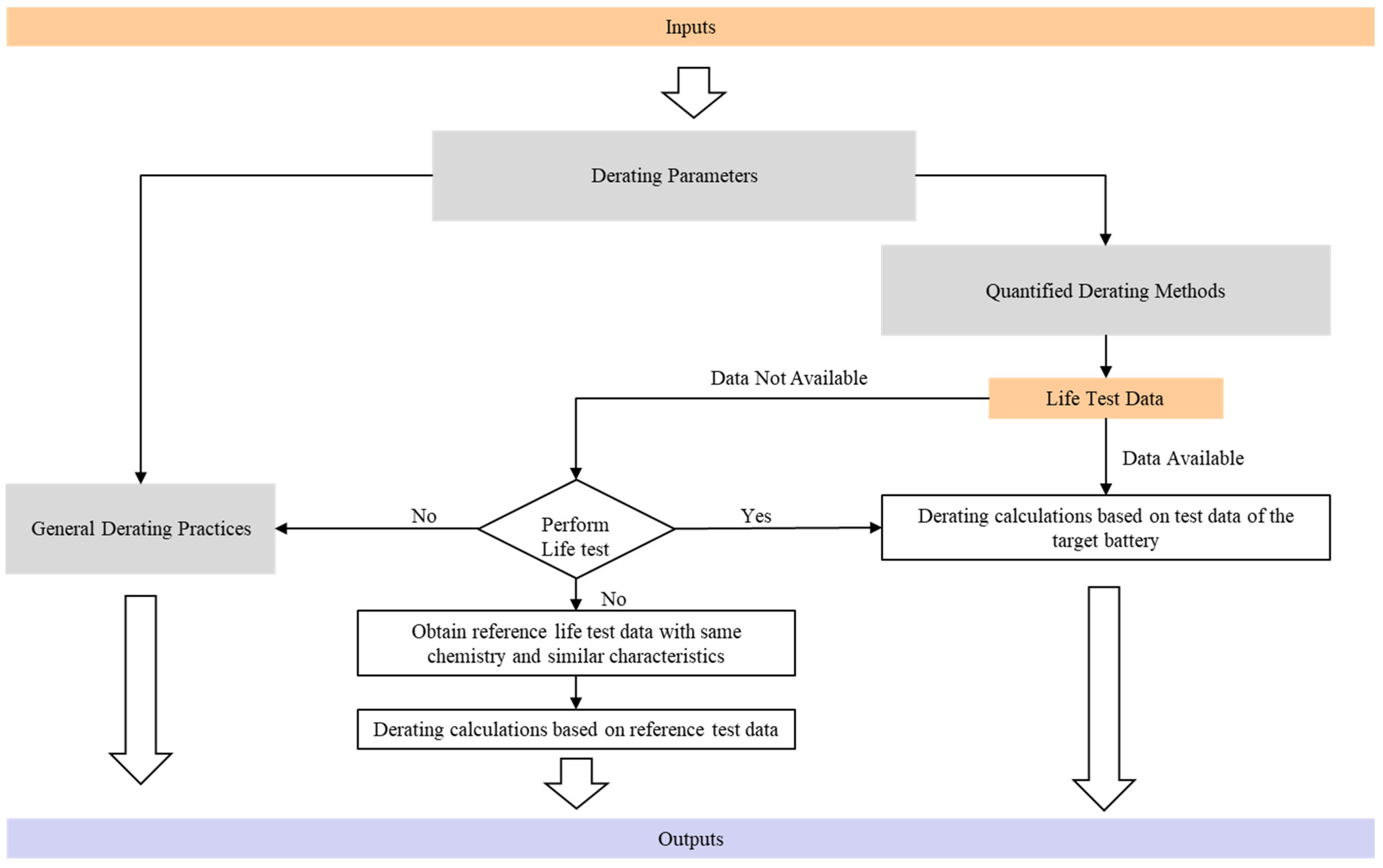
The developed methodology requires three inputs (
Figure 3): (1) battery information from the manufacturer, (2) battery degradation (life) data (typically capacity loss data), and (3) target lifetime. The battery information includes rated parameters, including capacity, voltage, current (C-rate), and temperature, all of which are provided in the datasheet. For quantitative derating, the rated value is used as the baseline (or reference) condition against which performance and degradation behavior under reduced-stress conditions are compared. The battery chemistry may also be determined, allowing for the identification of battery life data for batteries being considered for derating or for batteries with the same chemistry.
When both typical and minimum (or maximum) values are provided, the rated limits specified by the manufacturer should be used consistently with the intended design objective and applicable engineering requirements. It should also be recognized that datasheet values represent manufacturer specifications and may not fully capture cell-to-cell variation, production tolerances, or differences between manufacturing batches. Therefore, when statistical performance data, qualification-test results, or application-specific degradation data are available, they should be incorporated to refine the derating analysis. In cases where datasheet information is incomplete or test conditions are not fully reported, conservative engineering judgment and additional validation testing may be required before finalizing the derating recommendations.
Battery degradation data (life data) form the basis of the derating analysis, representing how capacity degrades under different conditions. Quantitative derating requires degradation data that link stress level to capacity loss. The most common form of degradation data includes capacity loss vs. time (calendar aging) and capacity loss vs. cycle number (cycle aging). The degradation dataset must include an identifiable stress condition (temperature, voltage, current), their initial state of charge (SOC), and measured capacity retention over time or cycles.
The minimum degradation data requirement for applying the developed method consists of one reference condition corresponding to a rated parameter limit and at least one additional condition representing a derated operating level. The reference condition provides the baseline degradation behavior, while the derated condition provides the calculation of the corresponding impact factor. Additional test conditions can improve confidence in the derating recommendation by allowing interpolation between stress levels. The selection of test conditions should be based on the rated parameter being evaluated. For example, temperature derating requires degradation data at two or more temperatures within the datasheet-specified operating range, whereas voltage or current derating requires degradation data collected at different voltage windows or C-rates. When degradation data for the target battery are unavailable, data from batteries with similar chemistry and design characteristics may be used as an initial reference.
The target lifetime or expected lifetime outcome defines the purpose of battery derating. This can be expressed as a target capacity after a defined storage period or a specified number of cycles, or as the required number of storage days or operating cycles before the capacity drops below a threshold.
The derating analysis is conducted after the derating parameters are determined (as illustrated in
Figure 4). If life-test data are not available, general derating practices can be applied, or calculations can be performed based on other life-test data that have the same chemistry and similar characteristics as the target battery.
The general derating practices for capacity, voltage, current (C-rate), and temperature limit control are intended to operate or store the battery at lower rated values (
Table 1). These practices do not evaluate the impact of derating but provide a practical way to reduce battery degradation. For capacity derating, the SOC may be held below 100% SOC on charge and above 0% SOC on discharge. For voltage derating, the inputs are the lower cutoff discharge (minimum) voltage and the upper cutoff charge (maximum) voltage. For current (C-rate) derating, the manufacturer-specified maximum allowable charge and discharge currents are considered. For temperature derating, relevant datasheet inputs include the minimum and maximum temperatures for storage, charging, and discharging. These rated parameter values from the datasheets serve as the baseline for derating strategies to achieve the desired outcomes.
In addition to supporting derating decisions, the developed approach can help optimize battery validation campaigns. Since the method identifies the rated parameters, degradation data requirements, and target lifetime objectives, testing efforts can be focused on the operating conditions most relevant to the intended application. Rather than evaluating all possible combinations of temperature, voltage, current, and state of charge conditions, engineers may prioritize degradation testing near critical rated limits and candidate derated conditions. This targeted approach can reduce the testing effort, shorten validation timelines, and improve the efficiency of battery qualification activities while still providing the information necessary to establish quantitative derating recommendations.
To quantify derating, a derating factor (DF) represents the magnitude of stress reduction relative to the rated (reference) condition specified in the battery datasheet, and an impact factor (IF) evaluates the resulting decrease in degradation.
The derating factor is defined as:
where
is the applied load under the derated condition, and
is the rated (reference) load specified in the datasheet. The stress
may represent temperature, voltage, or current (C-rate), depending on the parameter being derated. The interpretation of the derating factor is that when
DF = 1, there is no derating, and the operation is at the rated limit; when
DF < 1, a reduced stress is applied, which is a valid derating condition; when
DF > 1, the stress exceeds the rated limit and should be avoided.
The impact factor is defined as:
where
refers to the measured capacity loss (percentage) under the derated condition at time
t (or at a specified cycle number), and
refers to the measured capacity loss under rated conditions at the same time or cycle number.
The derating factor and impact factor are intended as comparative engineering metrics and are based on several assumptions. First, the analysis evaluates the influence of a selected derating parameter (e.g., temperature, voltage, or current) relative to the reference conditions, while other operating conditions are assumed to remain unchanged. Second, the impact factor is calculated using degradation data obtained at the same storage time or cycle number to ensure a consistent comparison between rated and derated conditions. Third, capacity loss is used as the primary degradation metric because it is the most commonly reported battery life indicator. Other degradation metrics, such as resistance growth or power fade, may also be incorporated when suitable data are available. Finally, the rated condition specified in the battery datasheet is treated as the reference operating condition from which derating margins are determined.
The interpretation of the impact factor is if , then . A higher impact factor means that derating results in less capacity loss. When , there is no derating being conducted and no improvements. When , derating has the benefit of a reduced capacity loss. When , derating has more negative impacts on the capacity loss, indicating that the selected condition results in greater degradation than the reference condition.
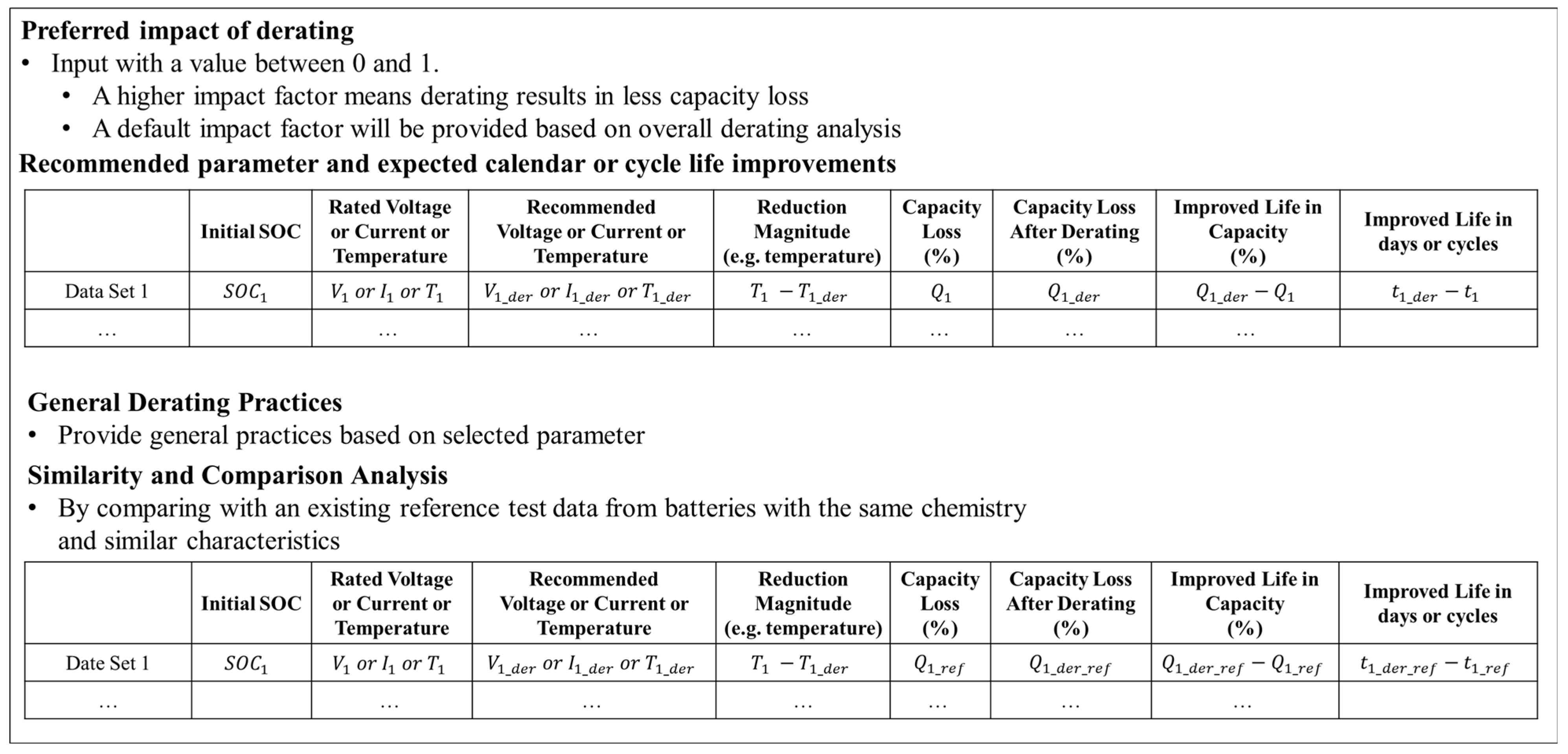
Based on the analysis, specific recommendations are generated for optimal operating conditions, including maintaining a controlled temperature range, operating the battery within a narrower voltage range, and applying reduced charge/discharge current limits. The outcome is a quantifiable extension of battery lifetime, measured through improvements in performance metrics associated with capacity over storage (calendar life) and cycling (cycle life). A summary of the derating output example is shown in
Figure 5.
Although the developed derating methodology is applicable to different lithium-ion battery chemistries, the specific derating recommendations will depend on the rated operating limits, which are chemistry-specific. For example, LFP batteries generally exhibit greater thermal stability and lower thermal runaway susceptibility than NMC or NCA batteries, whereas high-voltage chemistries such as NMC may be more sensitive to elevated voltage and high-SOC operation [
52]. Therefore, the relative importance of temperature, voltage, current, and capacity derating may vary among chemistries. The method accommodates these differences through the use of chemistry-specific degradation data and manufacturer-rated parameters while maintaining the same analysis procedure.
4. Case Study
An example of temperature derating for calendar life improvement is explained below, based on derating calculations using existing life-test data. The case study is intended to demonstrate the application of the developed methodology rather than establish a universal relationship between derating magnitude and lifetime extension. The resulting life improvement is derived from experimentally measured degradation behavior under different operating conditions rather than from a predictive aging model. Therefore, the accuracy of the derating recommendation depends on the quality and applicability of the degradation data used as inputs.
The required inputs are as follows. The battery datasheet describes the maximum storage temperature as 60 °C. Therefore, the input to the derating rated parameter is temperature, with the maximum rated value of 60 °C. The target outcome is to store the battery for 900 days, with a capacity loss of less than 10%. The life-test data were obtained from [
43] (based on existing LFP battery calendar life data for 900 days), and the required data inputs are presented in
Table 2.
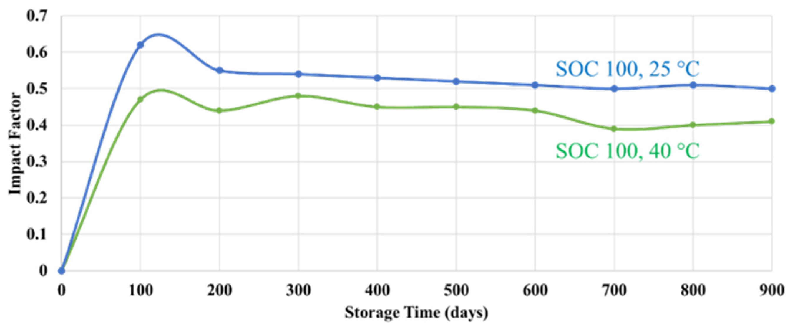
By evaluating the impact factor using the capacity loss at 60 °C as the reference condition, and 40 °C and 25 °C as derated conditions,
Figure 6 presents the impact factor over time. Derating to 25 °C produced a higher impact factor than derating to 40 °C, indicating greater reduction in capacity loss.
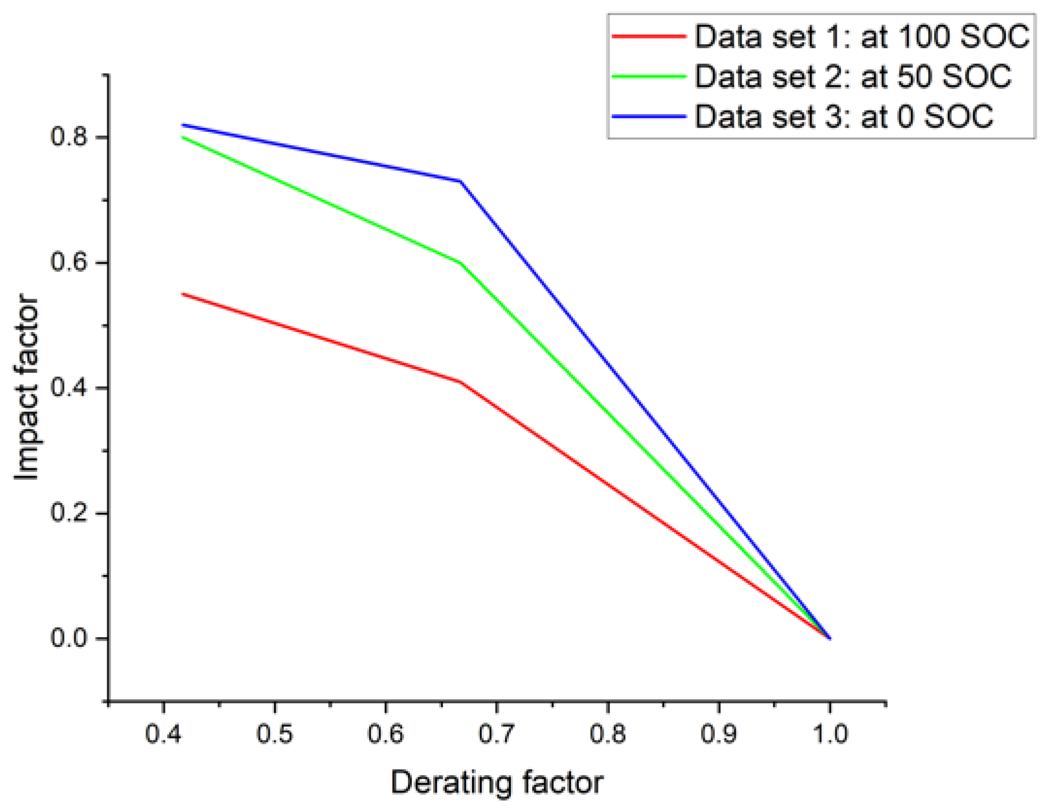
Figure 7 presents the relationship between the impact factor and the derating factor at a target lifetime of 900 days. The derating factor is calculated as 60 °C/60 °C = 1; 40 °C/60 °C = 0.67; and 25 °C/60 °C = 0.42, which scales the temperature stress ratio.
To determine the required level of derating, the impact factor threshold is derived from the target performance requirement using the quantitative derating method described in
Section 3. At the rated storage conditions of 60 °C and 100% SOC, the measured capacity loss at 900 days is 22%. The design requirement specifies that the target capacity loss is less than 10%. Therefore, the required fractional reduction in degradation relative to the rated condition can be calculated as:
which indicates that a minimum impact factor of approximately 0.55 is required to satisfy the lifetime target at 60 °C and 100% SOC.
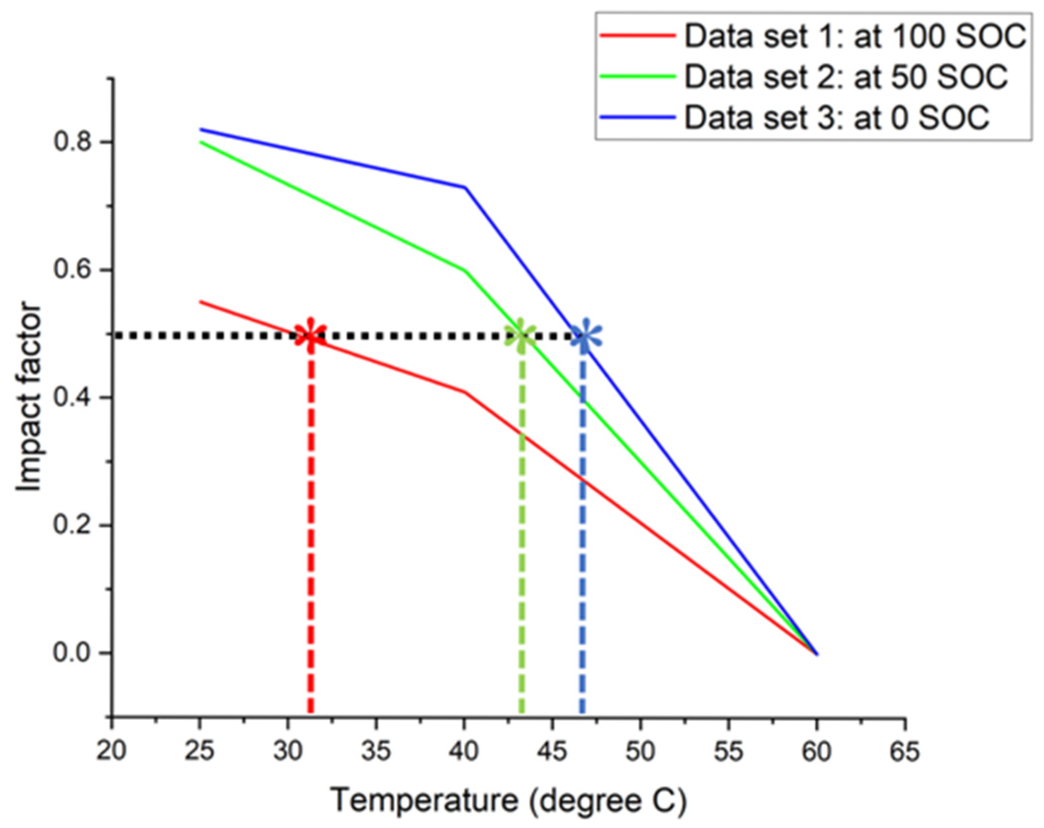
For practical graphical interpretation in the illustrative example below (
Figure 8), an impact factor value of 0.5 was used as an approximate threshold because it is close to the calculated requirement. It should be noted that the impact factor threshold is not fixed by the developed method and should be determined based on the target performance requirement and the corresponding reference degradation level. Different applications and lifetime targets may therefore require different impact factor thresholds.
Based on the degradation data, for storage at 100% SOC, the recommended temperature is 31 °C, representing a 29 °C reduction from the rated limit. This results in approximately 90% remaining capacity after 900 days, compared to 78% at 60 °C, corresponding to a 12% improvement in capacity retention. For batteries stored at 50% and 0% state of charge, the recommended temperatures are 43 °C (17 °C below 60 °C) and 47 °C (13 °C below 60 °C), resulting in increases of 10% and 1% in capacity. These outputs can also be generated if the designers prefer a higher derating impact, resulting in a greater temperature reduction from 60 °C. However, the trade-off between the cost and the feasibility and controllability must be considered.
Although derating generally reduces degradation and extends battery lifetime, the optimal derating level should also consider implementation cost and system requirements. For example, reducing the usable capacity window may require a larger battery pack to satisfy the same energy demand, while restricting charge or discharge current may reduce the available power or increase charging time. Similarly, maintaining lower operating temperatures may require additional thermal-management hardware and energy consumption. Therefore, the selection of derating margins involves a trade-off between increased capital expenditure (CAPEX) associated with battery oversizing or thermal-management systems and reduced operational expenditure (OPEX) resulting from longer battery life, improved reliability, reduced maintenance, and delayed battery replacement. The method provides quantitative estimates of degradation reduction and recommended derating margins based on available degradation data, which can support application-specific cost–benefit analyses when evaluating the trade-off between performance, lifetime, and implementation cost.
5. Conclusions
Although the concept of lithium-ion battery derating has been applied, a clear method for converting manufacturer datasheet-rated limits into quantitative derating margins has not been presented. During early-stage product design or battery selection, electrochemical aging models and real-time optimization frameworks may not be available. This study presented an approach that utilizes datasheet-rated parameters and degradation data to generate quantitative derating recommendations.
A key contribution is clarifying what information is minimally required to make derating decisions and how each input is used. Rated limits from the datasheet define the safe operating boundaries and serve as the reference condition. When life-test degradation data are available, the derating approach provides a quantitative path to estimate derating margins by comparing capacity-loss behavior under rated and reduced-load conditions. Two metrics, including the derating factor (stress reduction relative to the rated limit) and the impact factor (degradation reduction relative to the rated condition), provide an interpretable link between stress reduction and expected life improvement, and enable the selection of derating levels that satisfy a target lifetime requirement. While the case study demonstrates the derating application using temperature-based calendar aging data, the methodology is equally applicable to voltage, current, capacity, and multi-parameter derating strategies when suitable degradation data are available.