


Abstract
Owing to the increasing demand for wearable electronics, flexible energy storage devices, such as supercapacitors, have gained interest in the electronic industry. In this context, asymmetric configurations have emerged as a promising strategy for the development of wider potential window supercapacitors. On the other hand, MOF-derived synthesis of transition metal oxides is known to result in porous materials, which exhibit better electrochemical performance. In this work, a MOF-derived Fe2O3 coating on carbon fiber woven substrate is proposed as a negative supercapacitor electrode for asymmetric flexible devices. Moreover, the MOF calcination time was evaluated in order to ensure the best electrochemical performance possible, achieving for the sample calcined for 2 h a specific capacitance of 18.8 F/g at a current density of 200 mA/g and an excellent rate capability. In addition, not only was this promising material obtained, but an asymmetric flexible supercapacitor based on two MOF-derived TMO coatings on carbon fiber woven electrodes was manufactured and characterized as a proof of concept. This supercapacitor displayed a specific capacitance of 229 mF/cm2, an energy density of 0.067 mWh/cm2 and a power density of 0.11 mW/cm2 at 0.15 mA/cm2. Moreover, the flexible supercapacitor retained 94.1% of its capacitance even after being bent to 90°.
1. Introduction
Currently, the electronic market is starting to develop portable or wearable devices [1,2,3]. For the specific case of wearable devices, flexibility is interesting not only for improving the portability of current devices but also for designing devices with new functionalities [4]. Electronics with biomedical purposes are a perfect example of how flexibility invites a revolution in a field; thus, the use of wearable sensors has turned into the use of more suitable and adjustable devices that allow monitoring of biomedical responses and status [5,6]. Owing to this new significance of wearable electronics, the development of flexible energy storage devices such as batteries or supercapacitors has become a necessity [1,2,3,7]. Nevertheless, the polymeric electrolytes used in these devices inevitably decrease their electrochemical performance in comparison with those conventional devices that use liquid electrolytes. Thus, not only is it necessary to develop new polymeric electrolytes [3,8], which present better electrochemical performance, but also the compensation through the improvement of the other energy storage device components is essential. Hence, electrodes must be based on textiles or other flexible materials in order to ensure flexibility; simultaneously, they must display the best possible electrochemical performance. For this reason, one of the most commonly reported strategies for this electrode type is based on the use of a flexible subtract coated with high electrochemical performance materials [2,9,10,11,12].
In the case of supercapacitor (SC) electrodes, the electrochemical performance is mainly linked to the capacitance, the electrical conductivity and the potential window in which the material works [13]. Capacitance is due to two possible mechanisms, the electric double-layer capacitor and pseudocapacitance [14]. The first one depends primarily on the surface area [15], so nanostructured or porous coatings favor this phenomenon [16,17]. The second one depends fundamentally on the faradaic reaction between the active material and the electrolyte [18,19]. Thus, nanostructured and porous materials, which not only present a large surface area but also provide faradaic reactions, would be suitable coating materials for flexible supercapacitor electrodes. These reasons make MOF-derived transition metal oxides (TMOs) obtained through the calcination of MOFs, which partially retain their precursor porosity, appear as promising coating candidates despite their relatively low electrical conductivity due to their ceramic nature [20,21]. On the other hand, the design of the basic structure of the supercapacitor itself is essential when its performance needs to be improved. In this way, the use of electrodes made of different materials, usually called asymmetric SCs, has been widely reported as an effective way to increase the potential window [22]. Within this asymmetric supercapacitors category, the most common configuration is the hybrid asymmetric supercapacitors [23,24]. In these devices, the positive electrode acts as a pseudocapacitor and the negative one as an electric double-layer capacitor (EDLC). However, the specific capacitances displayed by common EDLC negative electrodes, such as graphene or graphite, are limited in comparison with pseudocapacitive electrodes [25], so the use of asymmetric supercapacitors based on two pseudocapacitive electrodes has emerged as an interesting alternative [26]. Some TMOs have been proposed as negative pseudocapacitive electrodes, such as MoS2 [27,28], MoOx [29] or FeMnO4 [30], with Fe-TMOs such as Fe2O3 or Fe3O4 [25,31,32,33,34,35,36,37,38] being some of the most promising ones due to their high specific capacitance, low cost and low toxicity.
In this work, carbon fiber fabrics are used as textile substrates to obtain negative electrodes for flexible devices after applying a MOF-derived Fe-TMO coating, with the aim of solving the previously described problems of the EDLC negative electrodes. The use of carbon fiber ensures the mechanical strength and flexibility of the electrode while acting as a current collector due to its high electrical conductivity. On the other hand, MOF-derived Fe-TMO nanostructured coating provides high specific capacitances due to its high porosity and pseudocapacitive behavior. Additionally, in order to ensure the most accurate electrochemical behavior, the temperature of the calcination step for TMO obtention from MOF has been optimized for this purpose. Finally, as a proof of concept, a wearable asymmetric supercapacitor was designed, fabricated, and characterized, integrating the developed negative electrode with a complementary positive counterpart. The positive counterpart consisted of a carbon fiber fabric coated with MOF-derived cobaltite spinel, widely used for this application [39,40,41,42,43,44,45,46], specifically a previously reported MOF-derived Ni-doped Co3O4 [47].
2. Materials and Methods
2.1. Materials
Plain weaving (1 × 1) (193 g/m2) of 3K AS4 GP carbon fiber supplied by Hexcel®. Iron(II) sulfate heptahydrate 99+% by Thermoscíentífíc (Fe(SO4)·7H2O). Sodium hydroxide pearls 1–2 mm purity > 98% by Labkem (NaOH). 1,3,5-Benzenetricarboxylix acid (H3BTC) 98% by Thermoscíentífíc. Sulfuric acid (H2SO4) 98% v/v. Nitric acid (HNO3) 65% v/v. Cobalt (II) nitrate (Co(NO3)2·6H2O) 98.0–102.0% by Thermoscíentífíc. 2-Methylimidazole (2-mIM) ˂ 98% by TCI. Poly(vinyl alcohol) (PVA) Mw 89.000–98.000, 99+% hydrolyzed by Sigma-Aldrich. Potassium hydroxide (KOH) 99% by Sigma Aldrich. Glass fiber E-Fiberglass plain weaving (110 g/m2) by Castro CompositesTM. All materials were used without further purification.
2.2. Synthesis of MOF-Derived Fe2O3@Fe3O4 Coating on Carbon Fiber
The manufacturing of the MOF-derived Fe2O3@Fe3O4 negative electrode was carried out according to our previous work [48]. First, prior to the coating synthesis, the carbon fiber (CF) fabrics are immersed in acetone for 48 h to remove the commercial sizing. Moreover, the CFs are also immersed in a mixture of H2SO4 and HNO3 in a proportion 3:1 in volume for 1 h. Through this treatment, the carbon fiber surface was partially oxidized, generating carbonyl, carboxyl and hydroxyl groups [49]. Then, fibers were washed with distilled water and dried overnight.
To manufacture the negative electrode, a MOF, namely MIL-100, was synthesized on the functionalized CF fabric for its future transformation into an Fe-TMO coating. At this point the MOF synthesis started, and the functionalized carbon fiber was immersed in 50 mL of an Fe(SO4)·7H2O 0.18 M solution for 10 min in order to favor the posterior MOF growth on the carbon fiber surface through electrostatic interactions between the cations and the functional groups previously generated on the fiber. Subsequently, 50 mL of a solution containing H3BTC 0.13 M and 0.36 M NaOH was added, and the mixture was stirred for 24 h, taking care to avoid damaging the fiber fabric during stirring. Finally, samples were fully washed with distilled water at 60 °C and dried at 60 °C overnight. After the carbon fiber is coated with the MOF MIL-100, calcination is necessary to obtain the Fe-TMO. The selected temperature was 350 °C, with the aim of reducing the possibility of deterioration of carbon fibers. To enhance the electrochemical performance of the samples, three different calcination times—0.5, 1 and 2 h (denoted as ox0.5, ox1, and ox2, respectively)—were studied to obtain the optimal conditions for their use as a supercapacitor negative electrode.
2.3. Manufacturing of Flexible Supercapacitor
2.3.1. Synthesis of Positive Electrode
Regarding the positive electrode manufacturing, another MOF, namely ZIF-L, was synthesized on the CF fabric for its transformation into a Ni-doped Co3O4 TMO coating similarly to a previous work [47]. To obtain the ZIF-L coating, the functionalized CF fabric was immersed in 50 mL of 0.05 M Co(NO3)2·6H2O for 10 min and another 50 mL of 0.4 M 2-mIM solution was added. After 1 h, the carbon fiber was removed, washed with distilled water, and dried overnight. Then, the MOF-coated CF fabric pieces were subjected to an ion-exchange process which consisted of immersing the pieces in a 10 mM Ni(NO3)2 solution for 10 min. At this point, it is important to note that the CF fabric pieces were cleaned with acetone and HNO3. Finally, the heat treatment required to obtain the Ni-doped Co3O4 TMO from the ZIF-L MOF was carried out in two steps. The first one was annealing at 500 °C for 1 h in Ar atmosphere to generate oxygen vacancies to improve the electrical conductivity [50], and the second one was calcination at 350 °C for 0.5 h.
2.3.2. Electrolyte and Assembly
Once both electrodes were synthesized, a flexible supercapacitor was manufactured as a proof of concept to demonstrate the applicability of the developed electrode in a flexible configuration. Fe-TMO-coated CF fabric was used as the negative electrode, while Ni-doped Co3O4-coated CF fabric was used as the positive electrode. Both electrodes were connected to copper collectors with silver ink to ensure electrical contact, and a glass fiber separator was put between them to avoid short-circuits. Finally, the aforementioned laminate sequence was embedded in a flexible polymer gel electrolyte composed of a 1 g/mL PVA and 0.1 g/mL KOH solution. After that, the samples were dried at room temperature overnight, completing the supercapacitor manufacturing process.
2.4. Material Characterization
The morphology of the coatings on the CF fabric was analyzed by scanning electron microscopy (SEM) using an S-3400 N by Hitachi (Chiyoda, Japan). Raman spectra were collected by a confocal laser micro-raman NT-MDT by NTegra Spectra (Apeldoorn, The Netherlands) with a 532 nm wavelength laser at 20 mW to determine the crystal structure of the coatings. Textural properties were studied by recording nitrogen adsorption/desorption isotherms on a Micrometrics (Norcross, USA) ASAP 2020 analyzer. Surface areas were calculated by the Brunauer, Emmett and Teller (BET) method, while pore size and volume were determined by the Barrett–Joyner–Halenda (BJH) method.
2.5. Electrochemical Characterization
The electrochemical performance of the electrodes was evaluated in a three-electrode system with a Ag/AgCl counter-electrode and a Pt electrode as the reference electrode in a KOH solution 2 M. Cyclic voltammetry (CV) and galvanostatic charge/discharge (GCD) measurements were collected on an Autolab (Utrecht, The Netherlands) PGSTAT302N potentiostat. The potential window for the Fe-TMO-based electrode was between 0 and −1 V. The stability of the Fe-TMO-based electrode was evaluated by measuring the specific capacitance after 5000 GCD cycles at 300 mA/g of current density using a NEWARE (Shenzhen, China) battery testing system, BTS4000-5V10MA. The flexible supercapacitor was also electrochemically characterized; in this case, CV and GCD measurements were obtained between 0 and 1.45 V and electrochemical impedance spectra (EIS) were acquired by applying 10 mV in a range of frequencies between 0.01 and 106 Hz. Additionally, the electrochemical performance of the flexible supercapacitor was also evaluated at various bending angles using both EIS and CV at 20 mV/s tests.
The specific capacitance values were calculated from CV tests as
where is the intensity, is the mass of the whole material, is the potential window, and is the scan rate [51].
On the other hand, the specific capacitance was calculated from GCD tests as
where is the current density, is the discharge time, and is the potential window [51].
Finally, energy density and power density of the flexible supercapacitor were calculated as [51]
3. Results and Discussion
3.1. Characterization of Fe2O3@Fe3O4 Electrodes
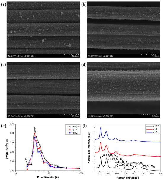
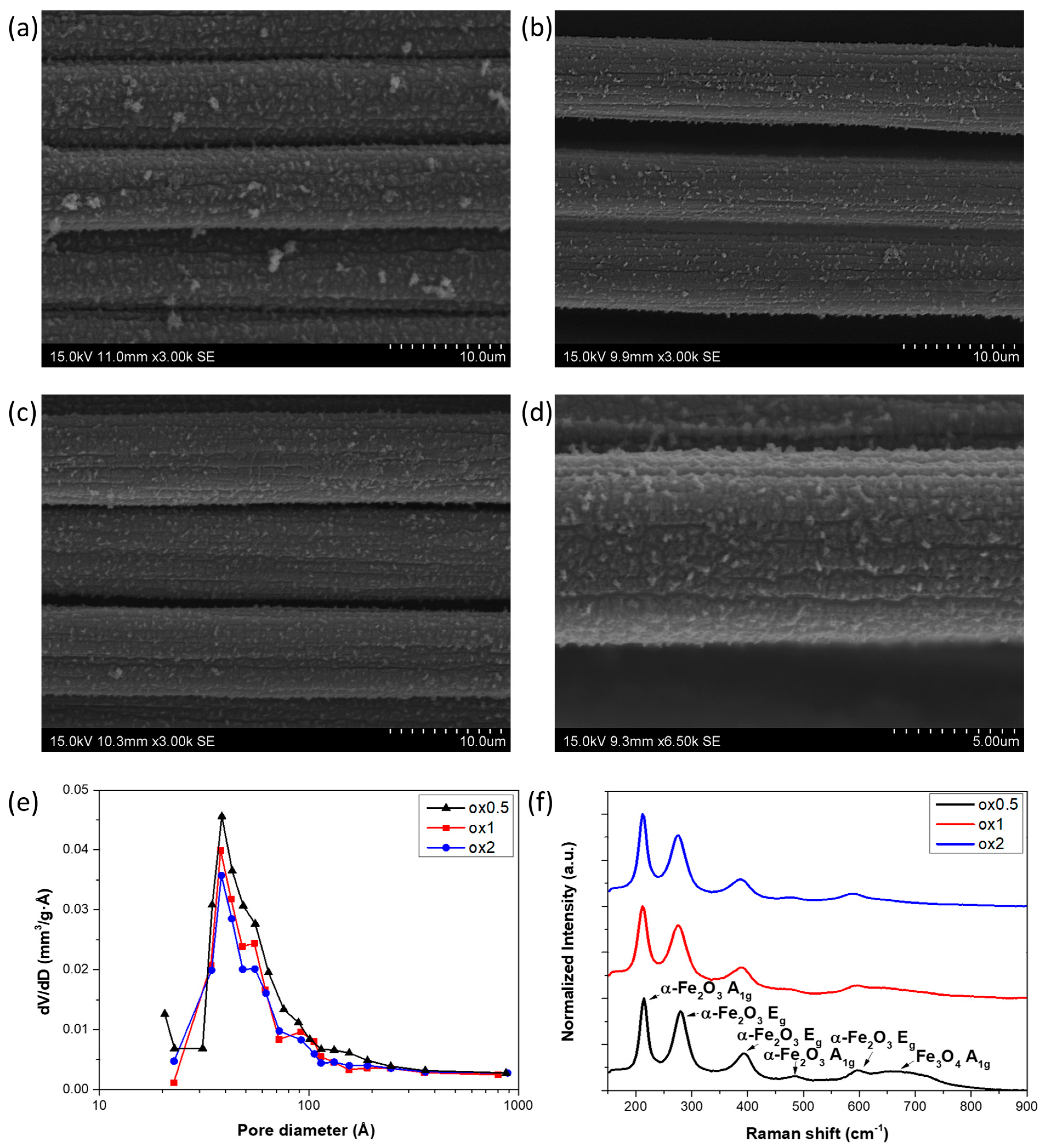
To initiate the electrode characterization, SEM images were taken with the aim of evaluating the morphology of the synthesized MOF coatings and the influence of the different calcination times in the final TMO coatings. Figure 1a, Figure 1b and Figure 1c show the SEM images of the samples ox0.5, ox1 and ox2, respectively. In all cases, a homogeneous coating that presents a large number of crystals on the carbon fiber surface can be observed, the main difference among samples being the clear tendency to reduce the size of the crystals by increasing the calcination time. The ox0.5 sample (Figure 1a) presents easily visible crystals that tend to decrease in size as the calcination time is increased, as can be seen for samples ox1 and ox2 (Figure 1b and Figure 1c, respectively). Figure 1d shows a higher-magnification SEM image of the sample ox2 to reveal the size of the crystals. In this image, the rifts among crystals are especially noticeable and suggest the crystal reduction could be related to a collapse of the structure during the calcination. This assumption was evaluated by nitrogen adsorption/desorption isotherm analysis. BET surface areas displayed by the samples in comparison with that exhibited by the virgin CF fabric used as a substrate are collected in Table 1. In this way, the obtained value for the CF was very low, only 0.2 m2/g, compared to the much higher values obtained for the coated fibers, which were 2.9 m2/g for the ox0.5 and ox1 samples, and 2.2 m2/g for the ox2 sample. From these results, it is deducible that applying a MOF-derived coating over the CF significantly increases the surface area of the samples. However, excessive calcination time can reduce the surface area, primarily due to the collapse of the MOF porous structure. The results show that all coated fibers displayed surface areas higher by an order of magnitude than the virgin carbon fiber, demonstrating the high porosity of the MOF-derived coatings. On the other hand, evaluating the second conclusion, the derivative of the pore volume with respect to the pore diameter is represented versus the pore diameter in Figure 1e. It is noticeable that there are two peaks, one at 38 Å and another at 55 Å, and both decrease as the calcination time increases, especially the second one, confirming that the structure collapses during this step. Finally, the coating composition was studied by Raman spectroscopy and the spectra are shown in Figure 1f. Raman spectra of three samples display peaks of about 227 and 497 cm−1, attributed to vibrational mode A1g of hematite, and about 290, 409 and 609 cm−1 attributed to hematite Eg [52]. However, a peak at 673 cm−1 was identified in the spectra of sample ox0.5. This peak is associated with the magnetite A1g vibrational mode [53]. Nevertheless, it is less evident as the calcination time increases. Thus, observed peaks are in agreement with other works [48], in which the obtained composition was a mixture of a main phase of hematite (α-Fe2O3) and a secondary phase of magnetite (Fe3O4), decreasing the magnetite phase as the calcination time increases.
Figure 1.
SEM images of samples (a) ox0.5, (b) ox1 and (c) ox2. (d) Detail of SEM image of sample ox2. (e) Pore volume distribution curves as a function of pore diameter, derived from the N2 adsorption/desorption isotherms. (f) Raman spectra. Reproduced from the first author’s Ph.D. thesis [54].
Table 1.
BET surface areas.
3.2. Electrochemical Performance of Fe2O3@Fe3O4 Electrodes
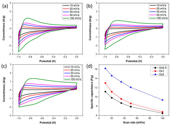
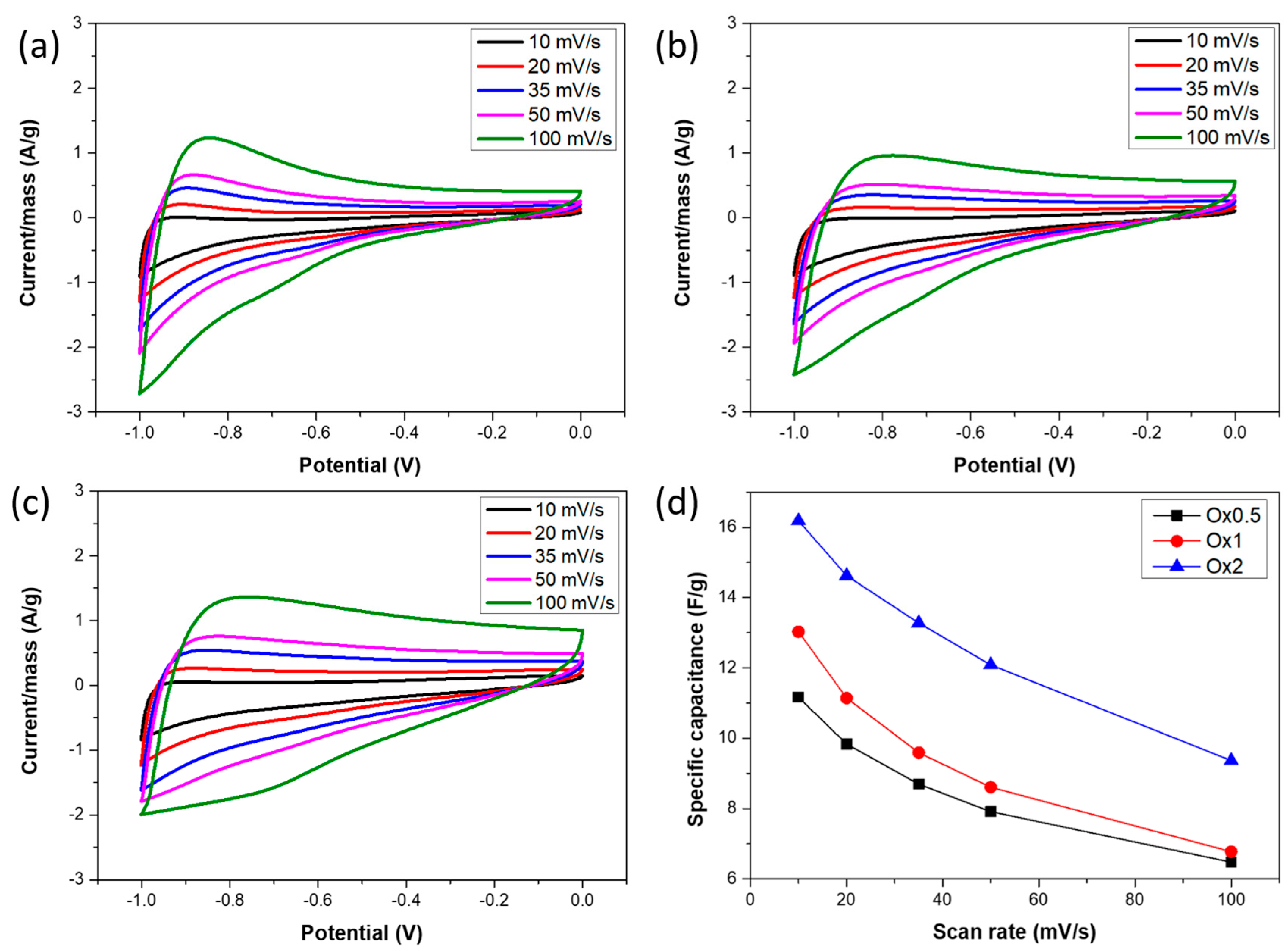
In order to study the electrochemical behavior of the samples, CV tests were carried out between 0 and −1 V at different scan rates. Figure 2a, Figure 2b and Figure 2c display the obtained CV curves for the samples ox0.5, ox1 and ox2, respectively. Based on these CV results, some peaks, which indicate pseudocapacitive behavior, can be observed at −0.85 V in the anodic process and at −0.9 V in the cathodic one. These peaks have been also observed previously in other works [55,56] and they are related to Fe reactions with OH− anions in the electrolyte. Comparing the samples among them, it is possible to observe that the main shape difference occurs in the cathodic process in the range between 0 and −0.5 V, where the iron oxide peaks are not involved. The larger the calcination time, the more enclosed area exhibits the sample material in this voltage range. Moreover, it suggests an increment of EDLC behavior as the calcination time is increased. However, according to the BET results, a larger calcination time entails a lower surface area. Thus, EDLC behavior would be expected to be lower, in contrast to what actually occurs. The reason must be associated with the electrical conductivity of the samples. The collapse of the structure during the calcination involves the contraction of the coating layer, decreasing the electron pathways to the fibers which act as a collector. Moreover, specific capacitance was calculated from the CV curves and the results are summarized in Figure 2d. As expected, according to the area curves, ox2 exhibited the largest specific capacitance followed by ox1, while ox0.5 was the sample that displayed the lowest value. The specific capacitance of the sample ox2 was 16.18 F/g at a scan rate of 10 mV/s, representing a 45% increment compared to ox0.5 and a 24% increase compared to ox1. The specific capacitance of ox2 remained 9.36 F/g even at 100 mV/s, indicating that the material retains 57.8% of its capacitance even with a tenfold increase.
Figure 2.
CV tests at different scan rates of samples (a) ox0.5, (b) ox1 and (c) ox2. (d) Specific capacitances calculated from CV. Reproduced from the first author’s Ph.D. thesis [54].
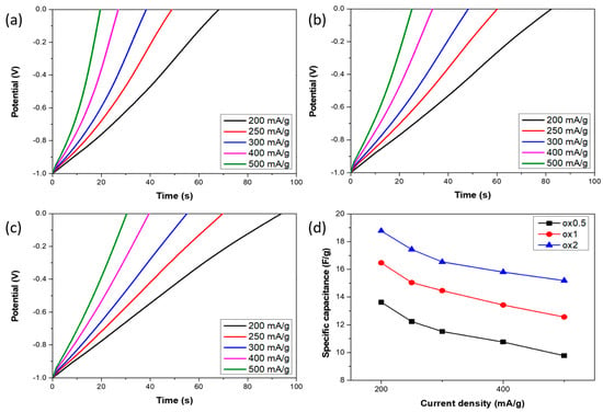
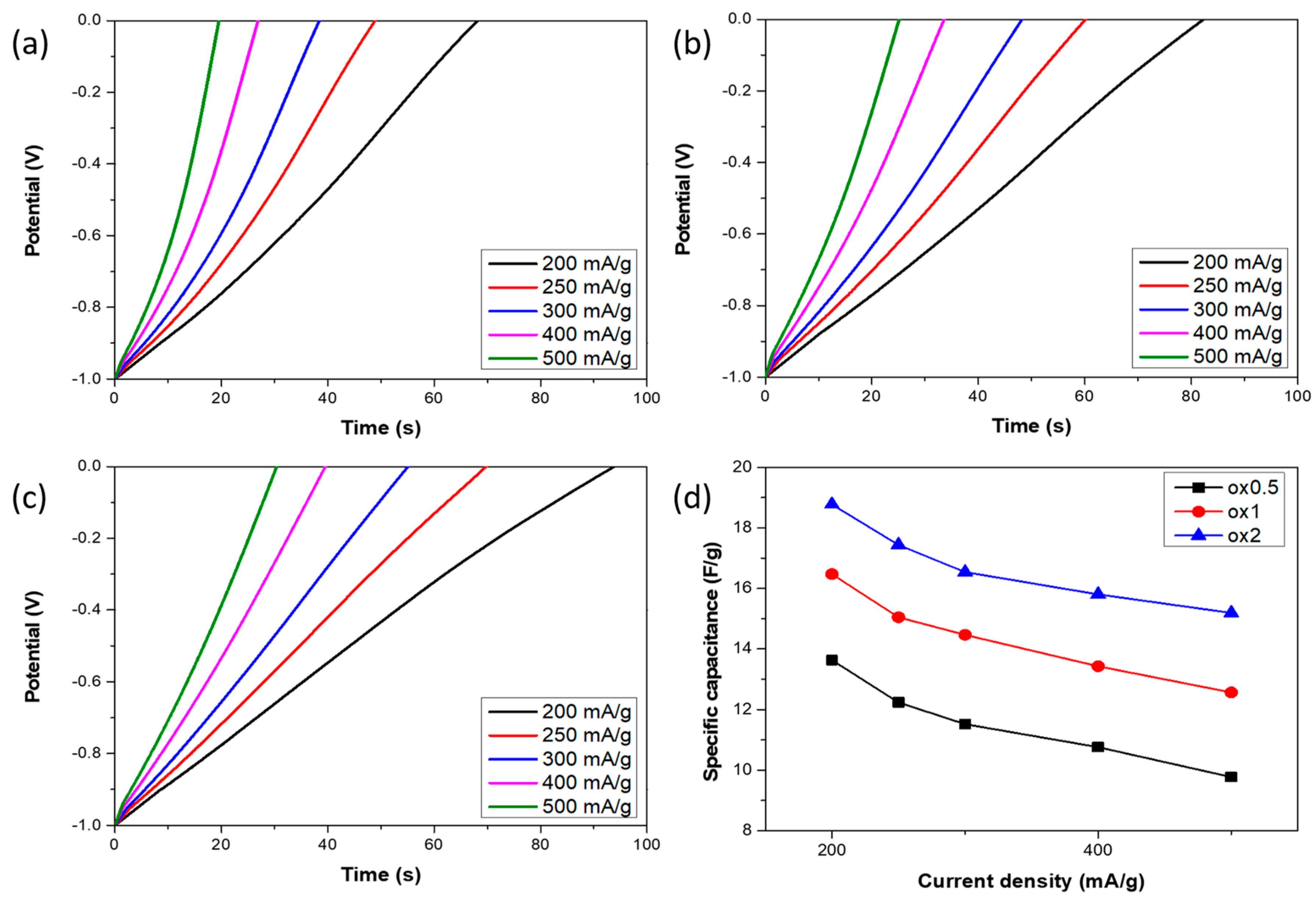
After CV analysis, GCD tests were carried out to provide information about the electrochemical performance as a negative supercapacitor electrode of the developed materials. Figure 3a, Figure 3b and Figure 3c show discharge curves at different current densities of samples ox0.5, ox1 and ox2, respectively. All of them show a non-linearity caused by a little plateau corresponding to the pseudocapacitive peak at −0.85 V in the anodic process observed in CV tests. Attending to the differences, it is possible to notice that the larger the calcination time, the less observable the plateau and the more linear the shape of the curves associated with a more EDLC behavior [14]. Moreover, the same tendency observed in the CV results is presented, so the discharge time, which is proportional to the capacitance, is larger as the calcination time increases. Thus, both specific capacitance values and discharge shapes follow the same behavior exhibited in the CV tests. Figure 3d summarizes the specific capacitance values calculated from GCD tests of each sample at different current densities. As mentioned above, sample ox2 exhibited the highest specific capacitance value, which was 18.8 F/g at a current density of 200 mA/g, while sample ox1 displayed 16.5 F/g and sample ox0.5 13.6 F/g at the same current density. These values are 12 and 28% lower than the one corresponding to the sample ox2. Moreover, the rate capability of each sample, which is related to the electrical conductivity, can also be evaluated from these values. The sample ox0.5 presented a specific capacitance of 9.8 F/g at 500 mA/g, the sample ox1 12.6 F/g and the sample ox2 15.6 F/g at this current density. Thus, the decrease in the specific capacitance value of each sample was 28% for sample ox0.5, 24% for sample ox1 and 19% for sample ox2. Hence, the greater the calcination time, the better the rate capability of the developed materials. This improvement of the rate capability is associated with an increment in the electrical conductivity, confirming the relationship between the calcination time and the electrical conductivity discussed above. The electrical conductivity improvement is associated with the shortening of electrical pathways as the coating layer contracts during the calcination.
Figure 3.
Discharge curves of GCD tests at different current densities for samples (a) ox0.5, (b) ox1 and (c) ox2. (d) Specific capacitances calculated from GCD tests. Reproduced from the first author’s Ph.D. thesis [54].
Based on the comparison of the developed material with the literature in Table 2, the obtained value of the capacitance normalized by total electrode mass could be normalized by active mass considering that the mass loading was 0.9% and by surface considering the areal density of the substrate, 193 g/m2. In this way, the obtained values were 2089 F/g and 366 mF/cm2. Comparing these values with the other reported works displayed, it is observable that the specific capacitance normalized by the active mass is noteworthy, while the specific areal capacitance is moderate due to the low mass loading value.
Table 2.
Comparison of the developed material with the literature.
Owing to the sample ox2 displaying not only a higher specific capacitance but also a better rate capability, this calcination time was selected for the development of the negative electrode of the flexible asymmetric supercapacitor and a further characterization was carried out. For this purpose, the kinetic controlling mechanism was studied through CV tests. Equation (5) shows the peak intensity (i) can be deconvoluted into two components, one kinetically controlled by capacitive surface processes, which depends proportionally on the scan rate (ν), and the other controlled by diffusion, which depends proportionally on the square of the scan rate (ν1/2) [63,64].
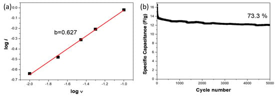
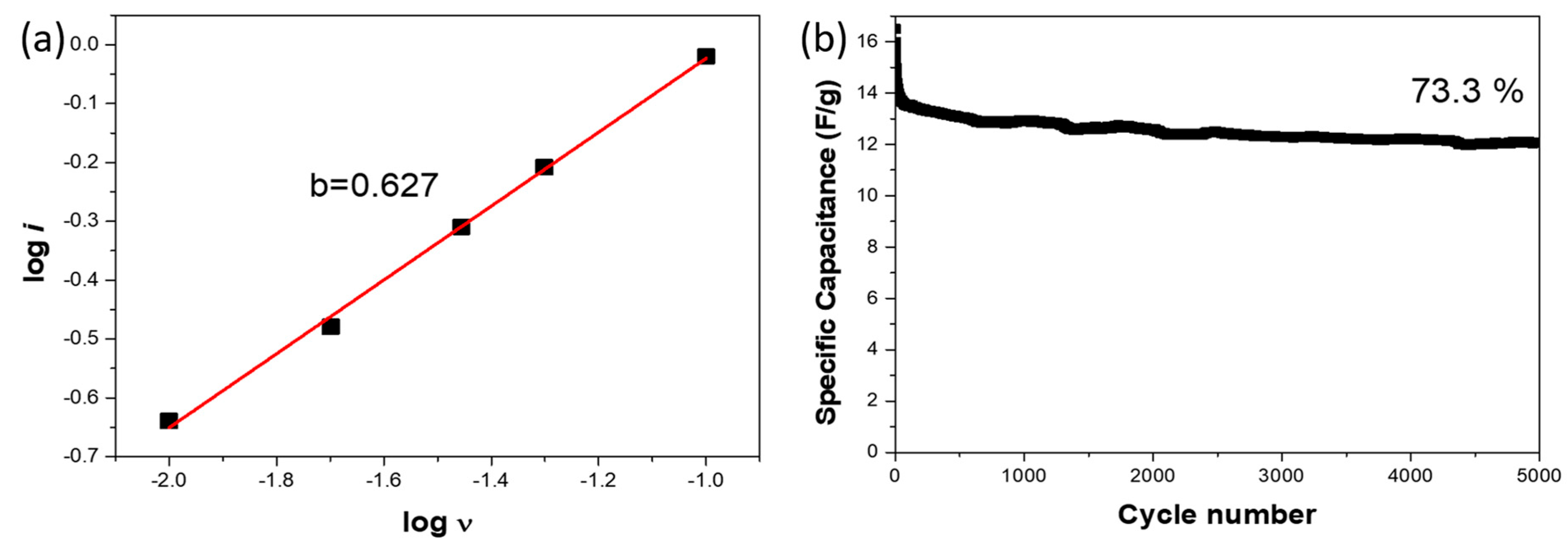
Thus, representing log(i) vs. log(ν) it is possible to evaluate the influence of each mechanism. A slope value of 1 would indicate a completely surface-controlled mechanism, while a slope value of 0.5 would indicate a completely diffusion-controlled mechanism. This representation for sample ox2 is available in Figure 4a. The obtained slope (b) value was 0.63, exhibiting a mainly diffusion-controlled behavior. Furthermore, its performance after several cycles was evaluated. Figure 4b shows the specific capacitance of the sample ox2 after 5000 GCD cycles at a current density of 300 mA/g. The total decrease in the initial specific capacitance after 5000 GCD cycles was 27%. However, this decrease was not homogeneous. A notable decrease of 11% of the capacitance after the 10 first cycles is observed. Next, between the 10th and the 1000th cycles the decrease is less evident, reducing to 13% of the initial specific capacitance and only by 3% between the 1000th and the 5000th cycles. Then, it is possible to conclude that after an initial activation stage, the capacitance stabilizes and exhibits only a minor decay (~3%) between 1000 and 5000 cycles, indicating the good long-term stability of the electrode.
Figure 4.
(a) Representation of logarithm of CV peak current vs. logarithm of scan rate and calculated b value of sample ox2. (b) Specific capacitance evolution of sample ox2 along 5000 cycles. Reproduced from the first author’s Ph.D. thesis [54].
3.3. Characterization of Asymmetric Flexible Supercapacitor
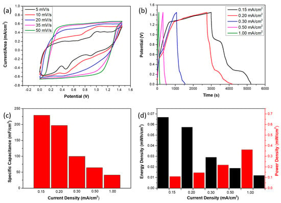
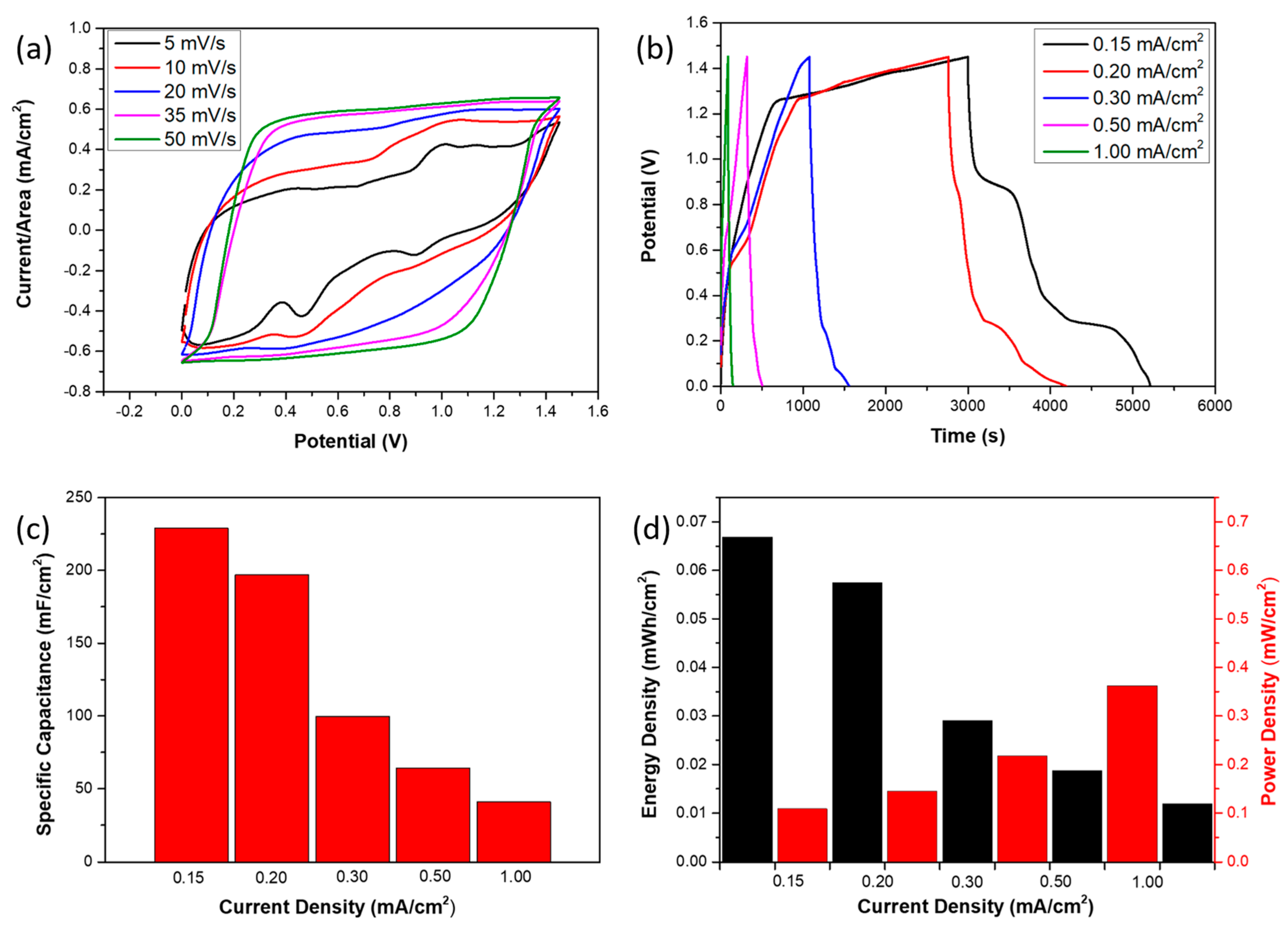
Once the flexible supercapacitor was assembled, using the Fe-TMO-coated CF fabric as the negative electrode and the Ni-doped Co3O4 TMO-coated CF fabric as the positive electrode, the supercapacitor was electrochemically characterized. The CV curves at different scan rates are displayed in Figure 5a. The presence of peaks associated with faradaic reactions is evident from the curve at 5 mV/s. The peaks that occur at about 1 V in the cathodic process and about 0.9 V in the anodic process are attributed to the MOF-derived Ni-doped Co3O4 coating on a CF fabric, the positive electrode. On the other hand, the peaks at about 0.3 in the cathodic process and about 0.4 and 0.1 V in the anodic process are attributed to the MOF-derived Fe2O3@Fe3O4 coating on the other CF fabric, the negative one. Regarding the curves at higher scan rates, it is noticeable that the higher the scan rate, the less remarkable the peaks are, indicating a lower pseudocapacitive contribution to the supercapacitor capacitance. In addition, the CV curves acquire a rectangular shape, typical of the EDLC mechanism [14]. Thus, this evolution as the scan rate increases suggests that faradaic reactions are kinetically limited at high scan rates due to the worse diffusion of OH− into the polymeric gel electrolyte in comparison with an aqueous electrolyte. These presented CV curves can be related to GCD curves at different current densities, as shown in Figure 5b. The peaks in the anodic process can be easily associated with the plateaus in the discharge step of the GCD curve. The peaks at 0.9 and 0.4 V are remarkable at 0.15 mA/cm2 of current density. However, only the second plateau at 0.20 mA/cm2 and none of them at 0.3 mA/cm2 are observable. This fact is in agreement with the previously obtained results in the CV tests, since the increment of the current density, which is equivalent to the scan rate, involves a lack of a pseudocapacitive mechanism contribution in favor of an EDLC behavior. Additionally, the specific capacitance was calculated from these GCD tests and the results are summarized in Figure 5c. The specific capacitance of the flexible supercapacitor was 229 mF/cm2 at a current density of 0.15 mA/cm2. This value was reduced by 14% to 196.8 mF/cm2 when the current density was increased to 0.20 mA/cm2. Nevertheless, the reduction was more dramatic in the increment from 0.20 to 0.30 mA/cm2 since the reduction was 49.4%, resulting in a value of 99.6 mF/cm2. The obtained values at 0.5 and 1 mA/cm2 were 64.4 and 41.0 mF/cm2, respectively, which involve a less dramatic reduction in this current density range. The pronounced reduction between the lower current densities is due to the loss of pseudocapacitive contribution observed in both CV and GCD curves. The energy density and the power density displayed during the GCD tests were also calculated and are shown in Figure 5d. The maximum energy density was 0.067 mWh/cm2 and it occurs at 0.15 mA/cm2 of current density. The power density at this current density was 0.11 mW/cm2. On the other hand, the maximum power density occurs at 1 mA/cm2 and the displayed value was 0.73 mW/cm2.
Figure 5.
(a) Flexible supercapacitor CV curves at different scan rates. (b) Flexible supercapacitor GCD curves at different current densities. (c) Calculated specific capacitances and (d) the corresponding energy and power density. Reproduced from the first author’s Ph.D. thesis [54].
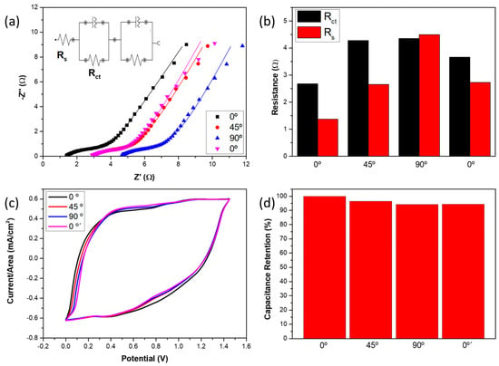
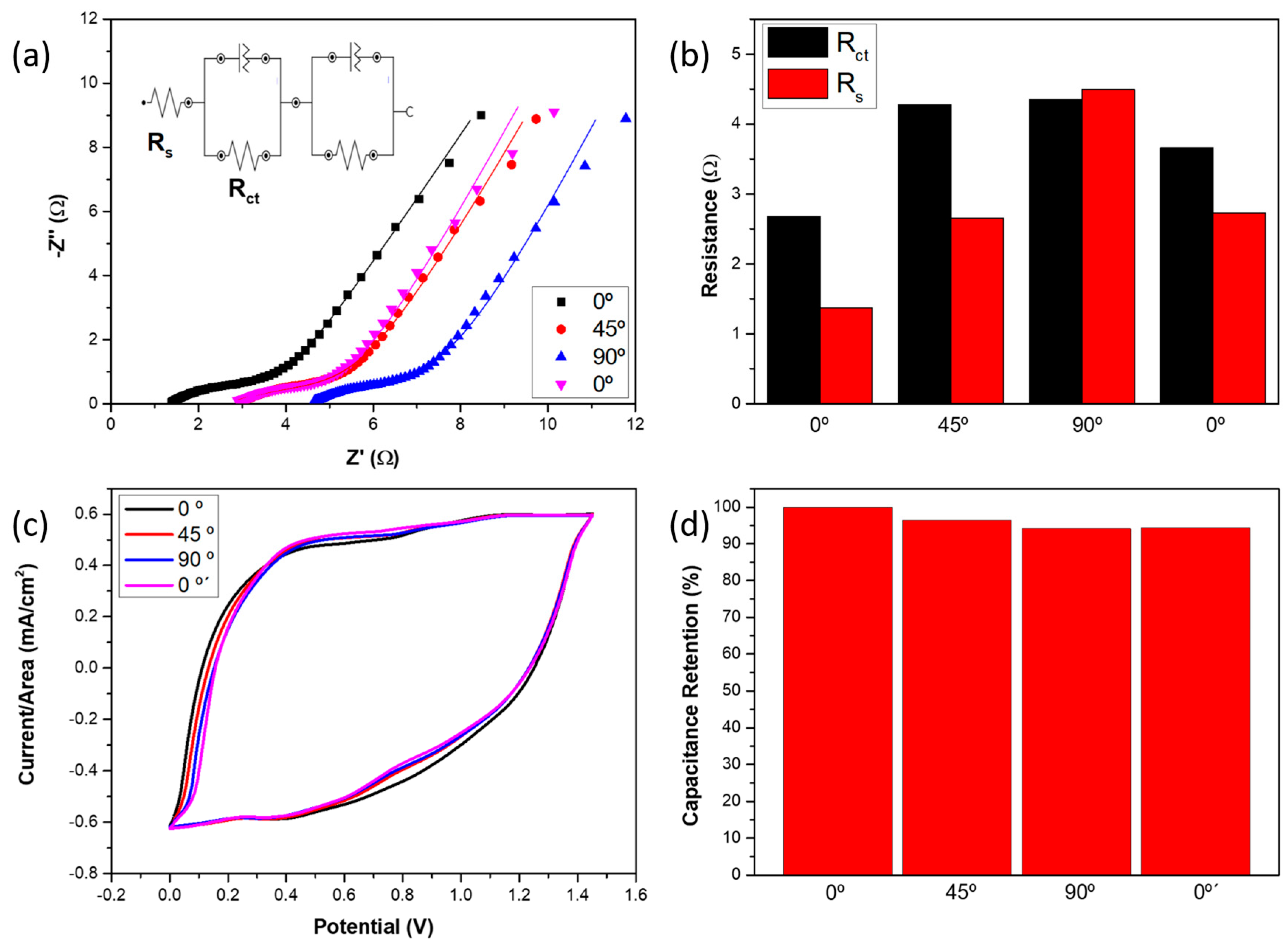
Finally, to evaluate the electrochemical performance of the flexible supercapacitor under mechanical deformation, EIS measurements were carried out at different bending angles. The Nyquist plots shown in Figure 6a were fitted using an equivalent circuit model, consisting of a series resistance (Rs), a charge transfer resistance (Rct), and an additional resistance component associated with the separator [51,65,66]. The fitted curves show good agreement with the experimental data, supporting the validity of the selected model. In this framework, Rs corresponds to the intrinsic resistance of the electrodes and current collectors, while Rct is associated with the charge transfer process at the electrode/electrolyte interface. The additional resistance is attributed to the separator contribution within the device. The extracted fitting parameters are summarized in Figure 6b. For the supercapacitor in the initial position (0°), the values obtained were Rct = 2.68 Ω and Rs = 1.37 Ω. Upon bending to 45° and 90°, the charge transfer resistance increases significantly to 4.28 and 4.35 Ω, respectively. This increase can be attributed to partial loss of effective contact between the electrode and the gel electrolyte under mechanical deformation. After returning to the initial position (0°′), the Rct value decreases to 3.66 Ω, corresponding to a recovery of approximately 41% of the resistance increase induced during bending. Regarding the series resistance, a more gradual increase with bending angle is observed, reaching 2.65 Ω and 4.49 Ω at 45° and 90°, respectively. This behavior is attributed to rearrangement and partial agglomeration of the coatings caused by the deformation of the carbon fiber substrate, which affects the conductive pathways. After releasing the bending (0°′), Rs partially recovers to 2.73 Ω, indicating that approximately 56% of the resistance increase is reversible. Finally, the capacitance retention of the supercapacitor was evaluated by CV tests at 20 mV/s. The CVs are presented in Figure 6c and the results are summarized in Figure 6d. The supercapacitor retained 96.5% of its capacitance at a 45° bending angle and 94.1% at 90°, so these values indicate good capacitance retention. Nevertheless, the recovery is minimal (0.2%).
Figure 6.
(a) Nyquist plots of the flexible supercapacitor at different bending angles. (b) The obtained serial and charge transfer resistance. (c) CV curves of the flexible supercapacitor at 20 mV/s at different bending angles. (d) Capacitance retention at different bending angles. Reproduced from the first author’s Ph.D. thesis [54].
4. Conclusions
First, the MIL-100 MOF coating on CF fabrics was successfully used as a precursor to obtain an Fe-TMO coating through a calcination step at 350 °C. Different calcination times, 0.5 h, 1 h and 2 h, were evaluated in order to optimize the Fe-TMO coating performance as a negative supercapacitor electrode. Some morphological, textural and compositional differences among samples calcinated for different times were observed. As the calcination time is increased, a reduction in the coating thickness is observed, accompanied by a collapse of the structure, and an increase in the proportion of hematite phase to magnetite. These differences influence electrochemical performance. The sample ox2 displayed not only the best specific capacitance but also the best rate capability. The specific capacitance exhibited by this sample was 18.8 F/g at a current density of 200 mA/g, this value being 12% and 28% higher than the samples ox1 and ox0.5 at the same current density, respectively. Moreover, sample ox2 remained at 81% of its specific capacitance at 200 mA/g when the current density was increased to 500 mA/g, while samples ox1 and ox0.5 only retained 76% and 72%, respectively. This better performance of the sample calcined for 2 h was attributed to the shortening of the electron pathways as the coating layer collapsed. Owing to the aforementioned better performance, 2 h was the selected calcination time to develop the negative electrode of a flexible supercapacitor.
On the other hand, the manufactured flexible supercapacitor exhibited 229 mF/cm2 at a current density of 0.15 mA/cm2, which involved an energy density of 0.067 mWh/cm2 and a power density of 0.11 mW/cm2. In addition, the performance of the flexible device was also evaluated at different bending angles, retaining 94.1% of its capacitance at a bending angle of 90°. In conclusion, not only was a MOF-derived Fe2O3@Fe3O4 coating on carbon fiber woven substrate developed as a novel negative electrode, but its functionality was demonstrated in an asymmetric flexible supercapacitor in which both electrodes were based on MOF-derived TMO coatings on carbon fiber woven substrate.
Author Contributions
Conceptualization, A.G.-B., D.M.-D., J.A.-A., B.K.M., M.S. and A.U.; methodology, A.G.-B., D.M.-D., J.A.-A. and B.K.M.; formal analysis, A.G.-B., D.M.-D. and J.A.-A.; investigation, A.G.-B., D.M.-D. and J.A.-A.; writing—original draft preparation, A.G.-B.; writing—review and editing, D.M.-D., J.A.-A., B.K.M., M.S. and A.U.; visualization, A.G.-B., D.M.-D. and J.A.-A.; supervision, B.K.M., M.S. and A.U.; project administration, M.S. and A.U.; funding acquisition, M.S. and A.U. All authors have read and agreed to the published version of the manuscript.
Funding
This research was funded by the Agencia Estatal de Investigación of the Spanish Government, grant numbers MULTISENS PID2022-136636OB-I00 and PRE2020-094255.
Data Availability Statement
The original contributions presented in the study are included in the article, further inquiries can be directed to the corresponding author.
Conflicts of Interest
The authors declare no conflicts of interest.
References
- Khan, J.; Khan, A.; Rubab, B.; Jamshaid, F.; Al-Kahtani, A.A.; Dahshan, A. Exploring the Progression of Energy Storage toward Flexibility: Metal-Organic Framework and Conducting Polymer Aspects. Appl. Mater. Today 2023, 34, 101906. [Google Scholar] [CrossRef] [Scilit]
- Yasami, S.; Mazinani, S.; Abdouss, M. Developed Composites Materials for Flexible Supercapacitors Electrode: “Recent Progress & Future Aspects”. J. Energy Storage 2023, 72, 108807. [Google Scholar] [CrossRef] [Scilit]
- Nujud Badawi, M.; Kuniyil, M.; Bhatia, M.; Kumar, S.S.A.; Mrutunjaya, B.; Luqman, M.; Adil, S.F. Recent Advances in Flexible/Stretchable Hydrogel Electrolytes in Energy Storage Devices. J. Energy Storage 2023, 73, 108810. [Google Scholar] [CrossRef] [Scilit]
- Baburaj, A.; Naveen Kumar, S.K.; Aliyana, A.K.; Banakar, M.; Bairagi, S.; Stylios, G. Factors Affecting the Performance of Flexible Triboelectric Nanogenerators (F-TENGs) and Their Sensing Capabilities: A Comprehensive Review. Nano Energy 2023, 118, 108983. [Google Scholar] [CrossRef] [Scilit]
- Hesar, M.E.; Seyedsadrkhani, N.S.; Khan, D.; Naghashian, A.; Piekarski, M.; Gall, H.; Schermuly, R.; Ghofrani, H.A.; Ingebrandt, S. AI-Enabled Epidermal Electronic System to Automatically Monitor a Prognostic Parameter for Hypertension with a Smartphone. Biosens. Bioelectron. 2023, 241, 115693. [Google Scholar] [CrossRef] [Scilit]
- del Bosque, A.; Sánchez–Romate, X.F.; Patrizi, D.; del Río Sáez, J.S.; Wang, D.Y.; Sánchez, M.; Ureña, A. Ultrasensitive Flexible Strain Sensors Based on Graphene Nanoplatelets Doped Poly(Ethylene Glycol) Diglycidyl Ether: Mask Breathing Monitoring for the Internet of Things. Sens. Actuators A Phys. 2023, 358, 114448. [Google Scholar] [CrossRef] [Scilit]
- Chang, K.F.; Panda, P.K.; Hsieh, C.-T.; Yang, P.C.; Kataria, N.; Khoo, K.S. Solid-State Lithium Batteries with Cathode-Supported Composite Solid Electrolytes Enabling High-Rate Capability and Excellent Cyclic Performance. Batteries 2023, 9, 490. [Google Scholar] [CrossRef] [Scilit]
- Qin, G.; Wu, C.; Song, X.; He, W.; Yang, J.; Yu, X.; Chen, Q. Multifunctional Enhanced Energy Density Integrated Supercapacitor Based on Self-Healing Redox-Mediated Gel Polymer Electrolyte. Fuel 2024, 357, 130033. [Google Scholar] [CrossRef] [Scilit]
- Cai, Y.; Wang, Y.; Cheng, L.; Guo, S.; Liu, T.; Hu, Z.; Yu, H.; Chen, D.; Li, Y.; Yuan, H. Structure Design and Assembly Mode of Carbon Nanotube-Based Flexible Electrode Materials and Flexible Supercapacitors. J. Energy Storage 2023, 73, 109179. [Google Scholar] [CrossRef] [Scilit]
- Yan, Y.; Zhou, Y.; Li, Y.; Liu, Y. The New Focus of Energy Storage: Flexible Wearable Supercapacitors. Carbon Lett. 2023, 33, 1461–1483. [Google Scholar] [CrossRef] [Scilit]
- Artigas-Arnaudas, J.; Muñoz, B.K.; Sánchez, M.; de Prado, J.; Utrilla, M.V.; Ureña, A. Surface Modifications of Carbon Fiber Electrodes for Structural Supercapacitors. Appl. Compos. Mater. 2022, 29, 889–900. [Google Scholar] [CrossRef] [Scilit]
- Mishra, A.; Shetti, N.P.; Basu, S.; Raghava Reddy, K.; Aminabhavi, T.M. Carbon Cloth-Based Hybrid Materials as Flexible Electrochemical Supercapacitors. ChemElectroChem 2019, 6, 5771–5786. [Google Scholar] [CrossRef] [Scilit]
- Zhang, S.; Pan, N. Supercapacitors Performance Evaluation. Adv. Energy Mater. 2015, 5, 1401401. [Google Scholar] [CrossRef] [Scilit]
- Mathis, T.S.; Kurra, N.; Wang, X.; Pinto, D.; Simon, P.; Gogotsi, Y. Energy Storage Data Reporting in Perspective—Guidelines for Interpreting the Performance of Electrochemical Energy Storage Systems. Adv. Energy Mater. 2019, 9, 1902007. [Google Scholar] [CrossRef] [Scilit]
- Conway, B.E. Electrochemical Supercapacitors: Scientific Fundamentals and Technological Applications; Springer: Berlin/Heidelberg, Germany, 1999. [Google Scholar]
- Salunkhe, R.R.; Young, C.; Tang, J.; Takei, T.; Ide, Y.; Kobayashi, N.; Yamauchi, Y. A High-Performance Supercapacitor Cell Based on ZIF-8-Derived Nanoporous Carbon Using an Organic Electrolyte. Chem. Commun. 2016, 52, 4764–4767. [Google Scholar] [CrossRef] [Scilit] [PubMed]
- Liu, B.; Shioyama, H.; Jiang, H.; Zhang, X.; Xu, Q. Metal-Organic Framework (MOF) as a Template for Syntheses of Nanoporous Carbons as Electrode Materials for Supercapacitor. Carbon N. Y. 2010, 48, 456–463. [Google Scholar] [CrossRef] [Scilit]
- Yadav, S.; Sharma, A. Importance and Challenges of Hydrothermal Technique for Synthesis of Transition Metal Oxides and Composites as Supercapacitor Electrode Materials. J. Energy Storage 2021, 44, 103295. [Google Scholar] [CrossRef] [Scilit]
- Zhu, X. Recent Advances of Transition Metal Oxides and Chalcogenides in Pseudo-Capacitors and Hybrid Capacitors: A Review of Structures, Synthetic Strategies, and Mechanism Studies. J. Energy Storage 2022, 49, 104148. [Google Scholar] [CrossRef] [Scilit]
- Pathak, M.; Jeong, S.M.; Rout, C.S. Spinel NiCo2O4 Based Hybrid Materials for Supercapacitors: Recent Developments and Future Perspectives. J. Energy Storage 2023, 73, 108881. [Google Scholar] [CrossRef] [Scilit]
- Liu, D.; Wu, Z.; Zhan, N.; Wang, Z.; Peng, Y.; Li, M.; Li, Z.; Huang, Z.; Gao, F.; Cheng, Z.; et al. Construction of Flower-like Spherical CoFe2O4@Co3O4 Based on Zeolitic Imidazolate Framework as High-Performance Electrode Materials for Supercapacitors. J. Energy Storage 2023, 73, 109158. [Google Scholar] [CrossRef] [Scilit]
- Ramachandran, T.; Sana, S.S.; Kumar, K.D.; Kumar, Y.A.; Hegazy, H.H.; Kim, S.C. Asymmetric Supercapacitors: Unlocking the Energy Storage Revolution. J. Energy Storage 2023, 73, 109096. [Google Scholar] [CrossRef] [Scilit]
- Anand, S.; Ahmad, M.W.; Hossain, S.S.; Choudhury, A. A Review on Metal-Organic Framework Hybrid-Based Flexible Electrodes for Solid-State Supercapacitors. Ionics 2023, 29, 4437–4467. [Google Scholar] [CrossRef] [Scilit]
- Du, X.; Lin, Z.; Wang, X.; Zhang, K.; Hu, H.; Dai, S. Electrode Materials, Structural Design, and Storage Mechanisms in Hybrid Supercapacitors. Molecules 2023, 28, 6432. [Google Scholar] [CrossRef] [Scilit] [PubMed]
- Li, J.; Chen, D.; Wu, Q. α-Fe2O3 Based Carbon Composite as Pure Negative Electrode for Application as Supercapacitor. Eur. J. Inorg. Chem. 2019, 2019, 1301–1312. [Google Scholar] [CrossRef] [Scilit]
- Mevada, C.; Mukhopadhyay, M. Limitations and Recent Advances in High Mass Loading Asymmetric Supercapacitors Based on Pseudocapacitive Materials. Ind. Eng. Chem. Res. 2021, 60, 1096–1111. [Google Scholar] [CrossRef] [Scilit]
- Rafique, A.; Zubair, U.; Serrapede, M.; Fontana, M.; Bianco, S.; Rivolo, P.; Pirri, C.F.; Lamberti, A. Binder Free and Flexible Asymmetric Supercapacitor Exploiting Mn3O4 and MoS2 Nanoflakes on Carbon Fibers. Nanomaterials 2020, 10, 1084. [Google Scholar] [CrossRef] [Scilit]
- Sari, F.N.I.; Ting, J.M. MoS2/MoOx-Nanostructure-Decorated Activated Carbon Cloth for Enhanced Supercapacitor Performance. ChemSusChem 2018, 11, 897–906. [Google Scholar] [CrossRef] [Scilit]
- Upadhyay, K.K.; Nguyen, T.; Silva, T.M.; Carmezim, M.J.; Montemor, M.F. Electrodeposited MoOx Films as Negative Electrode Materials for Redox Supercapacitors. Electrochim. Acta 2017, 225, 19–28. [Google Scholar] [CrossRef] [Scilit]
- Nagamuthu, S.; Vijayakumar, S.; Lee, S.H.; Ryu, K.S. Hybrid Supercapacitor Devices Based on MnCo2O4 as the Positive Electrode and FeMn2O4 as the Negative Electrode. Appl. Surf. Sci. 2016, 390, 202–208. [Google Scholar] [CrossRef] [Scilit]
- Aalim, M.; Shah, M.A. Role of Oxygen Vacancies and Porosity in Enhancing the Electrochemical Properties of Microwave Synthesized Hematite (α-Fe2O3) Nanostructures for Supercapacitor Application. Vacuum 2023, 210, 111903. [Google Scholar] [CrossRef] [Scilit]
- Cho, S.; Patil, B.; Yu, S.; Ahn, S.; Hwang, J.; Park, C.; Do, K.; Ahn, H. Flexible, Swiss Roll, Fiber-Shaped, Asymmetric Supercapacitor Using MnO2 and Fe2O3 on Carbon Fibers. Electrochim. Acta 2018, 269, 499–508. [Google Scholar] [CrossRef] [Scilit]
- Han, F.; Xu, J.; Zhou, J.; Tang, J.; Tang, W. Oxygen Vacancy-Engineered Fe2O3 Nanoarrays as Free-Standing Electrodes for Flexible Asymmetric Supercapacitors. Nanoscale 2019, 11, 12477–12483. [Google Scholar] [CrossRef] [Scilit] [PubMed]
- Li, F.; Liu, Y.L.; Wang, G.G.; Zhang, H.Y.; Zhang, B.; Li, G.Z.; Wu, Z.P.; Dang, L.Y.; Han, J.C. Few-Layered Ti3C2T: X MXenes Coupled with Fe2O3 Nanorod Arrays Grown on Carbon Cloth as Anodes for Flexible Asymmetric Supercapacitors. J. Mater. Chem. A Mater. 2019, 7, 22631–22641. [Google Scholar] [CrossRef] [Scilit]
- Tang, Q.; Wang, W.; Wang, G. The Perfect Matching between the Low-Cost Fe2O3 Nanowire Anode and the NiO Nanoflake Cathode Significantly Enhances the Energy Density of Asymmetric Supercapacitors. J. Mater. Chem. A Mater. 2015, 3, 6662–6670. [Google Scholar] [CrossRef] [Scilit]
- Chi, G.; Gong, W.; Xiao, G.; Pan, J.; Chen, J.; Su, L.; Fugetsu, B.; Sakata, I.; Zhang, X. Wire-Shaped, All-Solid-State, High-Performance Flexible Asymmetric Supercapacitors Based on (Mn,Fe) Oxides/Reduced Graphene Oxide/Oxidized Carbon Nanotube Fiber Hybrid Electrodes. Nano Energy 2023, 117, 108887. [Google Scholar] [CrossRef] [Scilit]
- Ma, J.; Guo, X.; Yan, Y.; Xue, H.; Pang, H. FeOx-Based Materials for Electrochemical Energy Storage. Adv. Sci. 2018, 5, 1700986. [Google Scholar] [CrossRef] [Scilit]
- Wan, H.; Hu, L.; Liu, X.; Zhang, Y.; Chen, G.; Zhang, N.; Ma, R. Advanced Hematite Nanomaterials for Newly Emerging Applications. Chem. Sci. 2023, 14, 2776–2798. [Google Scholar] [CrossRef] [Scilit]
- Mateen, A.; Javed, M.S.; Khan, S.; Saleem, A.; Majeed, M.K.; Khan, A.J.; Tahir, M.F.; Ahmad, M.A.; Assiri, M.A.; Peng, K.Q. Metal-Organic Framework-Derived Walnut-like Hierarchical Co-O-Nanosheets as an Advanced Binder-Free Electrode Material for Flexible Supercapacitor. J. Energy Storage 2022, 49, 104150. [Google Scholar] [CrossRef] [Scilit]
- Zhang, S.; Dai, P.; Liu, H.; Yan, L.; Song, H.; Liu, D.; Zhao, X. Metal-Organic Framework Derived Porous Flakes of Cobalt Chalcogenides (CoX, X = O, S, Se and Te) Rooted in Carbon Fibers as Flexible Electrode Materials for Pseudocapacitive Energy Storage. Electrochim. Acta 2021, 369, 137681. [Google Scholar] [CrossRef] [Scilit]
- Gong, H.; Bie, S.; Zhang, J.; Ke, X.; Wang, X.; Liang, J.; Wu, N.; Zhang, Q.; Luo, C.; Jia, Y. In Situ Construction of ZIF-67-Derived Hybrid Tricobalt Tetraoxide@Carbon for Supercapacitor. Nanomaterials 2022, 12, 1571. [Google Scholar] [CrossRef] [Scilit]
- Liu, S.; Kang, L.; Zhang, J.; Jung, E.; Lee, S.; Jun, S.C. Structural Engineering and Surface Modification of MOF-Derived Cobalt-Based Hybrid Nanosheets for Flexible Solid-State Supercapacitors. Energy Storage Mater. 2020, 32, 167–177. [Google Scholar] [CrossRef] [Scilit]
- Huang, T.; Lou, Z.; Lu, Y.; Li, R.; Jiang, Y.; Shen, G.; Chen, D. Metal-Organic-Framework-Derived MCo2O4 (M=Mn and Zn) Nanosheet Arrays on Carbon Cloth as Integrated Anodes for Energy Storage Applications. ChemElectroChem 2019, 6, 5836–5843. [Google Scholar] [CrossRef] [Scilit]
- Guan, C.; Liu, X.; Ren, W.; Li, X.; Cheng, C.; Wang, J. Rational Design of Metal-Organic Framework Derived Hollow NiCo2O4 Arrays for Flexible Supercapacitor and Electrocatalysis. Adv. Energy Mater. 2017, 7, 1602391. [Google Scholar] [CrossRef] [Scilit]
- Javed, M.S.; Aslam, M.K.; Asim, S.; Batool, S.; Idrees, M.; Hussain, S.; Shah, S.S.A.; Saleem, M.; Mai, W.; Hu, C. High-Performance Flexible Hybrid-Supercapacitor Enabled by Pairing Binder-Free Ultrathin Ni–Co–O Nanosheets and Metal-Organic Framework Derived N-Doped Carbon Nanosheets. Electrochim. Acta 2020, 349, 136384. [Google Scholar] [CrossRef] [Scilit]
- Wu, X.; Meng, L.; Wang, Q.; Zhang, W.; Wang, Y. Highly Flexible and Large Areal/Volumetric Capacitances for Asymmetric Supercapacitor Based on ZnCo2O4 Nanorods Arrays and Polypyrrole on Carbon Cloth as Binder-Free Electrodes. Mater. Lett. 2019, 234, 1–4. [Google Scholar] [CrossRef] [Scilit]
- González-Banciella, A.; Martinez-Diaz, D.; de Hita, A.; Sánchez, M.; Ureña, A. M-Doped (M = Zn, Mn, Ni) Co-MOF-Derived Transition Metal Oxide Nanosheets on Carbon Fibers for Energy Storage Applications. Nanomaterials 2024, 14, 1846. [Google Scholar] [CrossRef] [Scilit]
- González-Banciella, A.; Martinez-Diaz, D.; de Prado, J.; Utrilla, M.V.; Sánchez, M.; Ureña, A. MOF-Derived α-Fe2O3@Fe3O4 on Carbon Fiber Fabric for Lithium-Ion Anode Applications. J. Energy Storage 2024, 90, 111904. [Google Scholar] [CrossRef] [Scilit]
- Feng, M.; Wang, S.; Yu, Y.; Feng, Q.; Yang, J.; Zhang, B. Carboxyl Functionalized Carbon Fibers with Preserved Tensile Strength and Electrochemical Performance Used as Anodes of Structural Lithium-Ion Batteries. Appl. Surf. Sci. 2017, 392, 27–35. [Google Scholar] [CrossRef] [Scilit]
- Lim, G.J.H.; Liu, X.; Guan, C.; Wang, J. Co/Zn Bimetallic Oxides Derived from Metal Organic Frameworks for High Performance Electrochemical Energy Storage. Electrochim. Acta 2018, 291, 177–187. [Google Scholar] [CrossRef] [Scilit]
- González-Banciella, A.; Martinez-Diaz, D.; Artigas-Arnaudas, J.; Vázquez, M.V.; Sánchez, M.; Ureña, A. Influence of the Heat Treatment on the MOF-Derived Co3O4 Coatings on Carbon Fiber Fabrics Used for Structural Supercapacitor Applications. J. Alloys Compd. 2025, 1032, 181139. [Google Scholar] [CrossRef] [Scilit]
- Garg, P.; Mohapatra, L.; Poonia, A.K.; Kushwaha, A.K.; Adarsh, K.N.V.D.; Deshpande, U. Single Crystalline α-Fe2O3 Nanosheets with Improved PEC Performance for Water Splitting. ACS Omega 2023, 8, 38607–38618. [Google Scholar] [CrossRef] [Scilit]
- Varvara, S.; Berghian-Grosan, C.; Damian, G.; Popa, M.; Popa, F. Combined Electrochemical, Raman Analysis and Machine Learning Assessments of the Inhibitive Properties of an 1,3,4-Oxadiazole-2-Thiol Derivative against Carbon Steel Corrosion in HCl Solution. Materials 2022, 15, 2224. [Google Scholar] [CrossRef] [Scilit] [PubMed]
- Banciella, A.G. Recubrimientos de Óxidos de Metales de Transición Obtenidos a Partir de Precursores MOF Para El Desarrollo de Sistemas de Almacenamiento de Energía Multifuncionales. Ph.D. Thesis, Universidad Rey Juan Carlos, Madrid, Spain, 2025. [Google Scholar]
- Shao, W.; Li, M.; Wang, X.; Fu, N.; Yang, Z. High-Performance Cobalt-Doped Carbon Cloth Supported Porous Fe2O3 Flexible Electrode Material in Quasi-Solid Asymmetric Supercapacitors. J. Alloys Compd. 2022, 929, 167141. [Google Scholar] [CrossRef] [Scilit]
- Wei, Y.; Zhou, C.M.; Cao, X.M.; Sun, Z.J.; Wu, Q.; Liu, D.L.; Xing, Z.; Zhang, Q.G. Hierarchically Structured Fe2O3@C Hollow Acanthospheres on Carbon Cloth as Anodes for High-Performance Asymmetric Supercapacitors. J. Alloys Compd. 2022, 929, 167245. [Google Scholar] [CrossRef] [Scilit]
- Radhi, A.A.; Al-rubaiey, S.I.J.; Al-Rubaye, S. NH4F-Assisted and Morphology-Controlled Fabrication of Iron Cobaltite FeCo2O4 Nanoparticles on Carbon Fiber Cloth for Supercapacitor Applications. Chem. Pap. 2023, 78, 733–746. [Google Scholar] [CrossRef] [Scilit]
- Song, K.; Wang, X.; Wang, J.; Zhang, B.; Yang, R. Bifunctional Conducting Polymer Coated CoFe2O4 Core-Shell Nanolayer on Carbon Fiber Cloth for 2.0 V Wearable Aqueous Supercapacitors. ChemistrySelect 2019, 4, 1685–1695. [Google Scholar] [CrossRef] [Scilit]
- Song, K.; Wang, X.; Wang, J.; Zhang, B.; Yang, R. Hierarchical Structure of CoFe2O4 Core-Shell Microsphere Coating on Carbon Fiber Cloth for High-Performance Asymmetric Flexible Supercapacitor Applications. Ionics 2019, 25, 4905–4914. [Google Scholar] [CrossRef] [Scilit]
- Feng, W.; Pu, W.; Zheng, Y.; Wu, H.; Li, L.; Wei, X. Excellent Rate Capability Supercapacitor Electrodes with Highly Hydroxyl Ion Adsorption Capacity Enabled by P-Doped MnCo2O4 Nanotube Arrays. Appl. Surf. Sci. 2022, 599, 153908. [Google Scholar] [CrossRef] [Scilit]
- Shah, S.H.; Muhammad, D.; Alomar, M.; Ali, N.; Al-Hinaai, M.M.; Balushi, R.A. Al A Novel Approach of FeS/Fe2O3 and FeS/Fe3O4 Nanocomposites Electrode, Comparative Analysis of Supercapacitor Technologies for Energy Storage Applications. J. Alloys Compd. 2026, 1050, 185484. [Google Scholar] [CrossRef] [Scilit]
- Surendran, S.; Shyam, A.; Narayanan, B.N. Graphene-Assisted Nanopatterning of Fe3O4 Nanotubes Decorated with Fe2O3 for Supercapacitor Applications. J. Power Sources 2025, 657, 238204. [Google Scholar] [CrossRef] [Scilit]
- Muduli, S.; Pati, S.K.; Swain, S.; Martha, S.K. MoO3@ZnO Nanocomposite as an Efficient Anode Material for Supercapacitors: A Cost Effective Synthesis Approach. Energy Fuels 2021, 35, 16850–16859. [Google Scholar] [CrossRef] [Scilit]
- Muduli, S.; Chakraborty, R.D.; Verma, P.; Martha, S.K. Bio-Waste Derived Honeycomb Structured Activated Carbons as Anode Materials for Lead-Carbon Hybrid Ultracapacitors. J. Electrochem. Soc. 2022, 169, 090517. [Google Scholar] [CrossRef] [Scilit]
- Sánchez-Romate, X.F.; Del Bosque, A.; Artigas-Arnaudas, J.; Muñoz, B.K.; Sánchez, M.; Ureña, A. A Proof of Concept of a Structural Supercapacitor Made of Graphene Coated Woven Carbon Fibers: EIS Study and Mechanical Performance. Electrochim. Acta 2021, 370, 137746. [Google Scholar] [CrossRef] [Scilit]
- Wang, W.; Guo, S.; Lee, I.; Ahmed, K.; Zhong, J.; Favors, Z.; Zaera, F.; Ozkan, M.; Ozkan, C.S. Hydrous Ruthenium Oxide Nanoparticles Anchored to Graphene and Carbon Nanotube Hybrid Foam for Supercapacitors. Sci. Rep. 2014, 4, 4452. [Google Scholar] [CrossRef] [Scilit]

Disclaimer/Publisher’s Note: The statements, opinions and data contained in all publications are solely those of the individual author(s) and contributor(s) and not of MDPI and/or the editor(s). MDPI and/or the editor(s) disclaim responsibility for any injury to people or property resulting from any ideas, methods, instructions or products referred to in the content. |
© 2026 by the authors. Licensee MDPI, Basel, Switzerland. This article is an open access article distributed under the terms and conditions of the Creative Commons Attribution (CC BY) license.