1. Introduction
Nowadays, environmental protection and emission savings are becoming increasingly important. The transition from fossil fuels to sustainable energy storage systems is steadily increasing. Li-ion batteries (LIBs) have established themselves due to their long cycle life, high energy, and power densities and promising rate capabilities [
1,
2,
3]. Nevertheless, the expectations for batteries in various application areas have not yet been met or the demands placed on them are constantly increasing. In order to meet these expectations, batteries must be continuously improved.
Lithium–sulfur batteries (LSBs) have been researched extensively as a promising alternative to LIBs owing to their high theoretical specific capacity (1675 mAh·g
−1), low cost, environmental friendliness, and natural abundance of sulfur [
4,
5]. However, the practical application of LSB systems is still limited by several issues, namely the intrinsic electrical insulation of sulfur and its discharge product (Li
2S), the shuttle effect of intermediate lithium polysulfides (Li
2S
n, 4 ≤
n ≤ 8), and the drastic volumetric expansion of the sulfur cathode during lithiation [
6,
7]. These issues result in high capacity fading and a poor rate capability, especially when applying high C-rates [
8,
9,
10].
To overcome these challenges, a major review of the cathode design is required. In general, conventional sulfur cathodes are produced by casting a slurry mixture of sulfur as the active material, a non-conductive polymeric binder, and a non-binding conductive agent on a metal foil current collector. The binder increases the mechanical integrity, but it leads to a higher electrical resistance, which is why the carbon particles are required. The use of binder and conductive particles increases the production costs and limits the energy density. To overcome these drawbacks, binder-free cathodes are established as a good alternative. In these systems, sulfur is embedded directly in an electronically conductive and mechanically robust metal matrix, allowing the elimination of additives. Of the various production methods, composite electrodes prepared by electrochemical codeposition offer a highly effective pathway to achieving structural stability and electronic connectivity between sulfur and the current collector, as is shown in an earlier paper about the composite electroforming of functionalized sulfur into a metal matrix resulting in an additive-free alternative to the standard production methods [
11].
The most widely used metal matrix for 3D electrodes is nickel due to its high electrochemical stability, moderate cost, and nucleation behavior in aqueous systems [
12,
13,
14,
15]. While various studies have already demonstrated the potential of such composites, the majority of research approaches are still restricted to planar geometries with limited surface areas, which restrict the sulfur utilization and the cycling performance [
16].
For further performance improvement, recent efforts have focused on the development of 3D, porous current collectors. Porous frameworks reduce local current densities, enhance LIB mobility, and increase electrolyte impregnation, in addition to preventing polysulfide shuttling, therefore ensuring long-term cycling stability [
17,
18,
19,
20]. Manufacturing methods for these structures include melt diffusion [
21], sulfur infiltration [
22], chemical vapor deposition [
23,
24], wet chemical processes involving soluble sulfur-containing compounds [
25,
26], and mechanical infusion such as ball milling [
27]. Nonetheless, these methods generally require high temperatures, significant energy consumption, and poor homogeneity or toxic precursors, which restrict process scalability and environment-friendliness [
28].
In our previous work, we describe a successful approach to fabricating highly porous nickel substrates. For this, a highly porous, non-conductive high-impact polystyrene (HIPS) scaffold is 3D printed, then spray coated with a graphite-based conducting layer, and subsequently electroplated with a 5–30 µm thin layer of nickel from a nickel sulfamate electrolyte. Following the coating process, the support structure is dissolved with toluene. This method results in free-standing metallic frameworks with very competitive porosity and surface area density, while completely eliminating high-temperature processing or toxic solvents. The increased surface area of the highly porous 3D-structured electrodes, in comparison to foil electrodes, leads to short diffusion paths and high electrolyte accessibility and therefore to reduced charge transfer resistance and diffusion overpotential [
29].
The present study is a follow-up to our previous work. It reports the production of a porous nickel electrode with incorporated PTh-functionalized sulfur particles (S-PTh) for application in LSBs. The porous, non-conductive 3D-printed structure is coated with graphite and subsequently a thin pure nickel layer is deposited using pulse plating. S-PTh particles are then co-deposited into the growing nickel matrix through pulse-controlled composite plating to create a mechanically interlocked and electronically percolated Ni/S-PTh hybrid structure. Pulse plating is used to ensure a more uniform nickel layer formation by enhancing the initial seeding on the relatively poorly conducting graphite layer, which leads to more uniform layer growth [
30]. The avoidance of high-temperature treatments and hazardous reagents significantly improves the safety, energy efficiency, and scalability of the process.
By combining a scalable and low-temperature electrochemical process with the precise structural control by 3D printing, the present approach advances previous ones. The incorporation of S-PTh into the nickel structure during the electrodeposition is a notable difference from conventional sulfur infusion or melt infiltration processes. This novel process allows a mechanically stable and porous electrode without the need of adding binders or conductive additives, enabling a more efficient use of sulfur.
The manufactured Ni/S-PTh 3D cathodes are therefore characterized using digital light microscopy and galvanostatic cycling to evaluate the morphology and the electrochemical behavior. When tested in half cells, they show high sulfur utilization and promising cycling stability.
2. Materials and Methods
2.1. Preparation of the Substrate
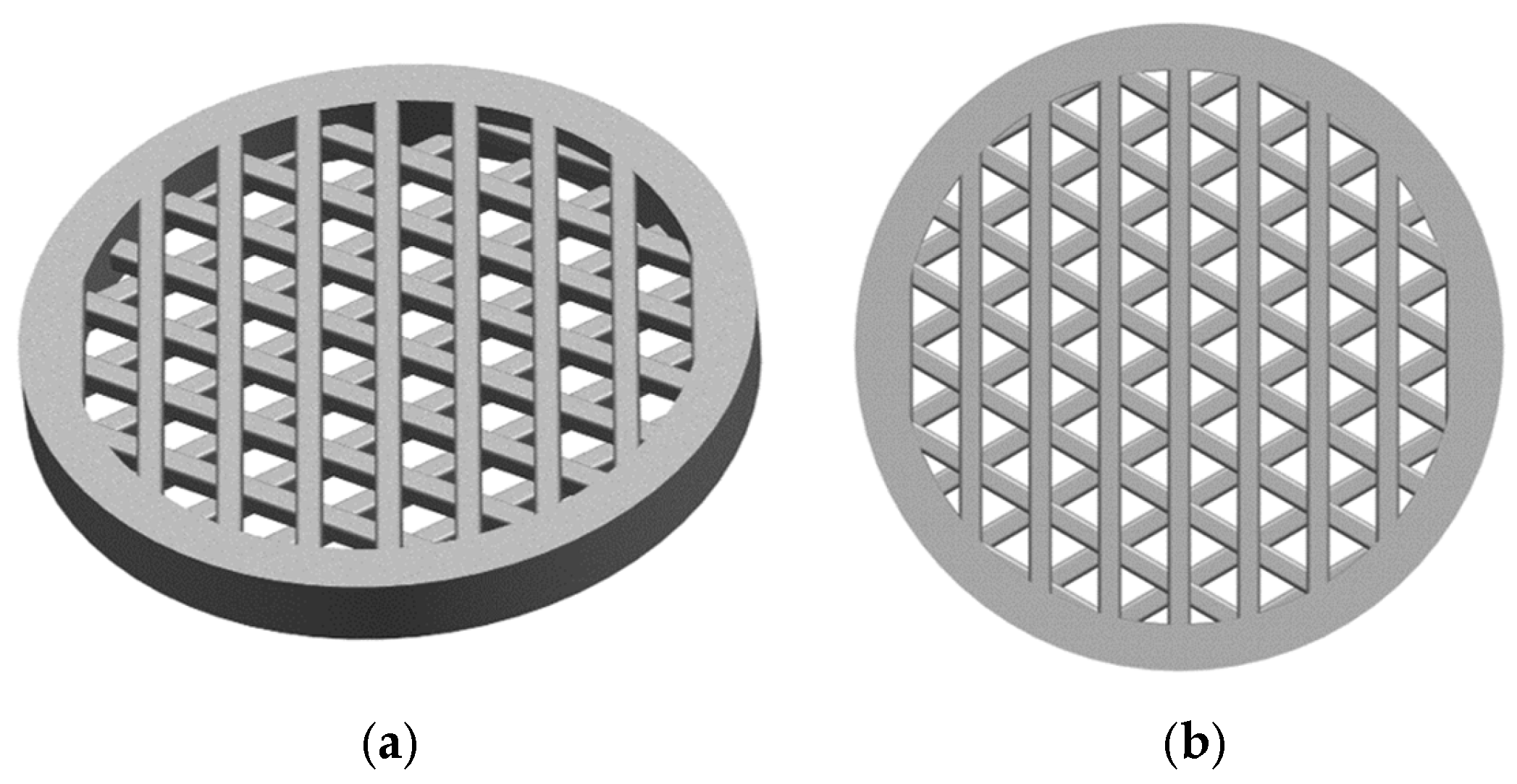
A round hollow cylinder with a diameter of 14 mm, an additional rim of 2 mm (to improve mounting), and a height of 1.4 mm was designed using CAD software (NX 12.0, Siemens Digital Industries Software, Plano, TX, USA). The inside of the hollow cylinder was filled with a grid structure consisting of three levels, each incorporating seven evenly spaced round struts, to ensure high surface area and porosity. The strut width is 0.5 mm and the resulting model is shown in
Figure 1, which illustrates the final CAD geometry.
The substrate shape and diameter are chosen in a way that the resulting electrode can be directly used in the coin cell configuration.
The substrates are manufactured using a simple FDM (fused deposition modelling)-based 3D printer (Anycubic Mega X, Anycubic Technology Co., Hong Kong, China) with a polyvinyl butyl (PVB) filament (Polymaker PolySmooth™, Polymaker, Shanghai, China). To ensure dimensional accuracy and mechanical stability during the printing process, a temporary support structure was constructed underneath the substrate, which was then removed with a cutter after the printing. Prior to electroplating, the non-conductive PVB substrates are made conductive by spray coating with a graphite-based lacquer (Graphite 33, Kontakt Chemie, Zele, Belgium). The conductive coating enabled uniform current distribution for the subsequent electrochemical deposition.
2.2. Electrochemical Deposition
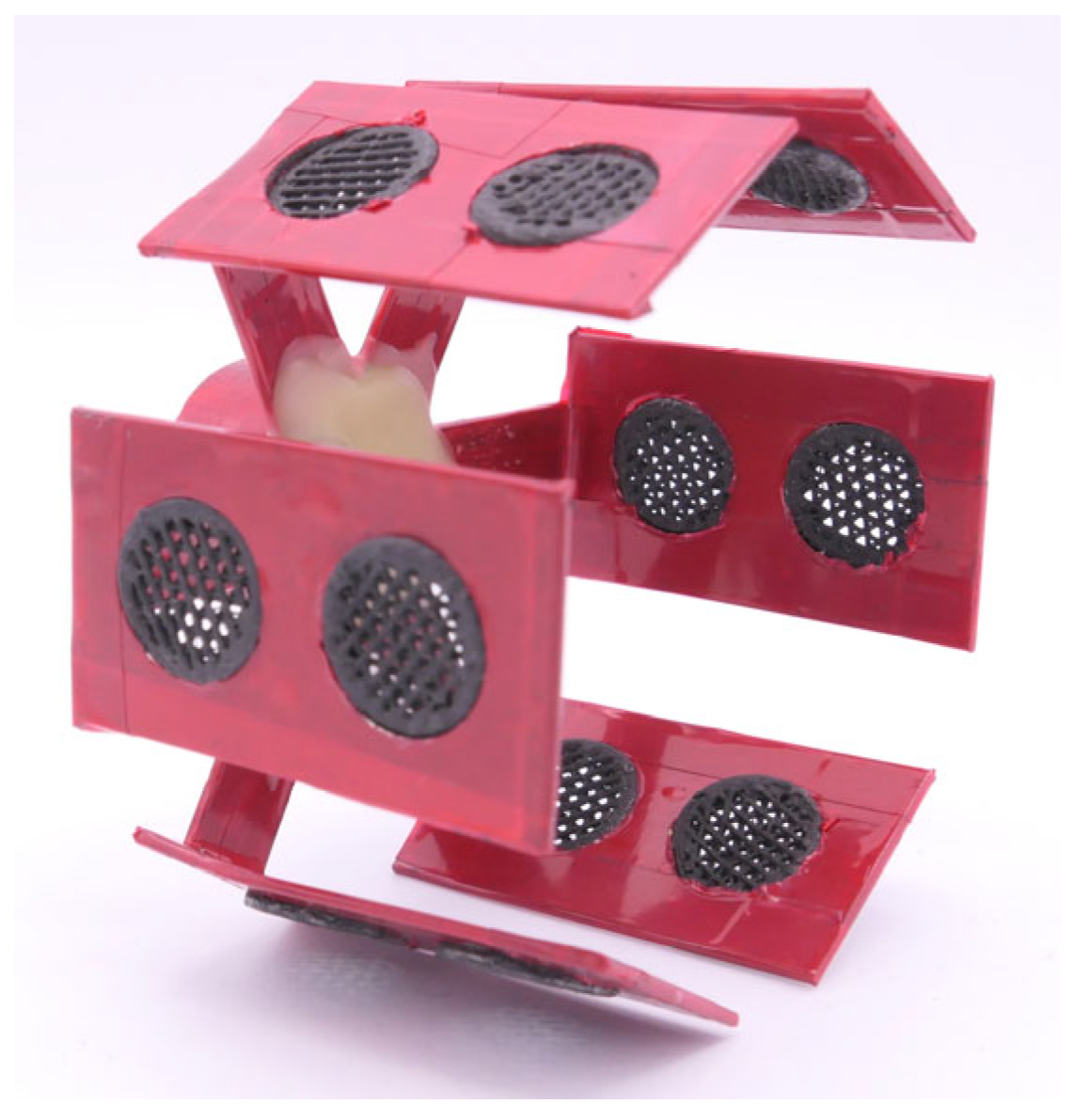
For the electrochemical deposition, a custom-made stainless steel holder is produced. In order to avoid any undesirable metallic deposition on the holder surface, and to electrically isolate it from the electrolyte, it is covered with a red masking tape (4154, 134 tesa SE, Norderstedt, Germany) and sealed with a layer of protective wax. The holder has six evenly spaced radial arms, each with two holes in which the substrates are inserted. This allows 12 substrates to be coated simultaneously.
Figure 2 illustrates the overall configuration, including the stainless steel holder with the inserted graphite-coated polymer substrates prior to the electrochemical plating process.
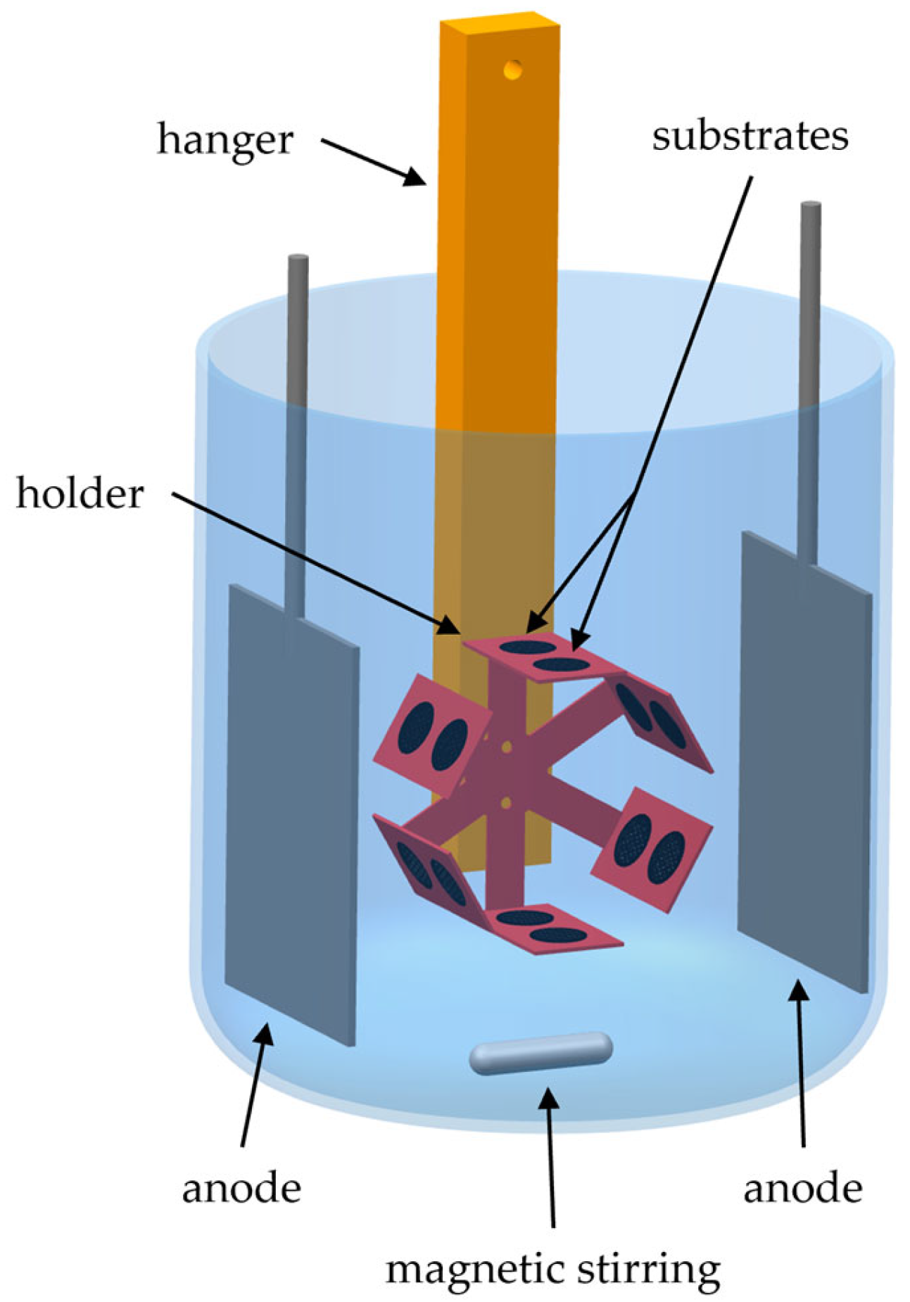
During the electrochemical depositions, the holder was centrally positioned between two sulfur-depolarized nickel anodes to achieve uniform current distribution and deposition on all of the mounted substrates. Electrical contact is established using a suspended metal hanger. In addition, the holder is mechanically connected to a stepper motor that ensures continuous rotation at 1 revolution per minute (rpm). To further improve the electrolyte homogeneity and the deposition uniformity, magnetic stirring is applied throughout the deposition process.
Figure 3 schematically illustrates the complete setup utilized during the electrochemical depositions.
A 6 µm thick nickel layer is deposited onto the graphite-coated polymer substrates using pulse plating, a technique selected to achieve a high nucleation rate, leading to a homogeneous and dense seeding of the surface with nickel grains, which subsequently can grow further. Additionally, pulse plating prevents dendritic growth and consequently ensures a homogeneous dense layer thickness across the 3D complex geometry of the substrates [
30]. A Watts nickel electrolyte (SLOTONIK 20, Dr.Ing. Max Schlötter GmbH & Co., KG, Geislingen, Germany) is prepared without the addition of wetting agents in order to prevent contamination of the surface or interference with the deposition uniformity. The electrolyte consists of high-purity nickel sulfate hexahydrate NiSO
4·6H
2O (DIN 50970 [
31], Wocklum, Balve, Germany) as the main nickel source, nickel chloride hexahydrate NiCl
2·6H
2O (DIN 50970, Wocklum, Balve, Germany) to improve anode dissolution and conductivity, and boric acid B(OH)
3 (DIN 50970, Wocklum, Balve, Germany) as a pH buffer [
32]. Pulse plating is carried out at a peak current density of 50 A·dm
−2 with an on-time of 20 ms and an off-time of 180 ms, resulting in a duty cycle of 10 %. The electrolyte temperature is maintained at 50 °C, and the magnetic stirring is held at 600 rpm. The process parameters are summarized in
Table 1.
Following the deposition of the initial nickel layer, a 9 µm thick Ni/S-PTh composite layer is co-deposited. For this purpose, a freshly prepared Watts nickel electrolyte is used with an identical base composition to that described earlier. No organic additives or wetting agents are included.
To increase dispersion stability and interfacial compatibility with the metal matrix, the sulfur particles are pre-functionalized with polythiophene; the specific synthesis and characterization route of the functionalization is described by Wu et al. [
33]. The functionalized sulfur particles are added to the electrolyte at a concentration of 10 g·L
−1. The composite deposition is carried out under galvanostatic conditions at a current density of 8 A·dm
−2 and the electrolyte temperature is regulated at 50 °C. For the acquisition of homogeneous sulfur particle suspension, as well as uniform co-deposition, magnetic stirring at 325 rpm is employed throughout the process (
Table 2). These operating conditions are optimized to maximize the mechanical entrapment of the functionalized sulfur particles within the growing nickel layer, and at the same time to preserve coating uniformity and adhesion.
2.3. Follow-Up Treatment
Following the composite electroplating process, the internal 3D-printed polymer scaffold is chemically dissolved. The substrates are immersed in technical-grade isopropanol (Stierand GmbH, Waldstetten, Germany) at room temperature for at least 12 h to ensure sufficient time for the dissolution of the PVB template material. For complete removal of the remaining polymer, the substrates are dipped in a fresh isopropanol bath and heated at 60 °C for an additional 2 h to ensure full dissolution of all of the residual filament pieces from the inner porous structure.
After dissolution, the substrates are dried for at least 12 h in reduced pressure, employing a vacuum oven at 40 °C and 200 mbar to remove residual solvent and moisture. After drying, the substrates are directly transferred into an argon-filled MBraun LabMaster glovebox (H2O, O2 < 0.1 ppm) (M. Braun Inertgas-Systeme GmbH, Garching, Germany) to prevent their contamination prior to electrochemical testing.
2.4. Electrochemical Setup and Measurements
Galvanostatic cycling measurements are carried out using CR2032 coin cells (MTI Corp., Richmond, VA, USA), assembled inside an argon-filled MBraun LabMaster glovebox (H2O, O2 < 0.1 ppm) (M. Braun Inertgas-Systeme GmbH, Garching, Germany).
The 3D, porous Ni–S electrode, manufactured with a diameter of 14 mm, can be directly used without any further mechanical modification, and it is placed in the positive casing of the coin cells. A Celgard 2500 separator (Celgard, Charlotte, NC, USA) of 16 mm diameter is placed on top of the cathode and wetted with 75 μL of electrolyte. The latter is composed of dimethoxyethane (DME, 99.5%) and 1,3-dioxolane (DOL, 99.8%) with 1:1 volume ratio, in which lithium bis(trifluoromethanesulfonyl)imide (LiTFSI, 99.95%) and lithium nitrate (LiNO3, 99.99%) are dissolved to achieve concentrations of 1 M and 0.5 M, respectively. All of the electrolyte components are supplied by Sigma Aldrich, Steinheim, Germany. A lithium metal disc (99.9 %, Sigma-Aldrich Chemie GmbH, Taufkirchen, Germany) of 14 mm diameter and 1 mm thickness is used and serves as counter and reference electrode, respectively. A stainless steel spacer and a wave spring are added to ensure uniform stack pressure and electrical contact within the cell. The coin cells are hermetically sealed by using a crimping tool (MTI Corp., Richmond, VA, USA) and applying a weight force of 0.9 tons.
3. Results and Discussion
3.1. Morphological Characterization of the Electrodes by Digital Light Microscopy
The surface morphology of the Ni/S electrodes is assessed by a digital light microscope (VHX-6000, Keyence Deutschland GmbH, Neu-Isenburg, Germany) under controlled illumination conditions, issued by a ring light, to ensure homogeneous lighting and to reduce surface reflection artifacts.
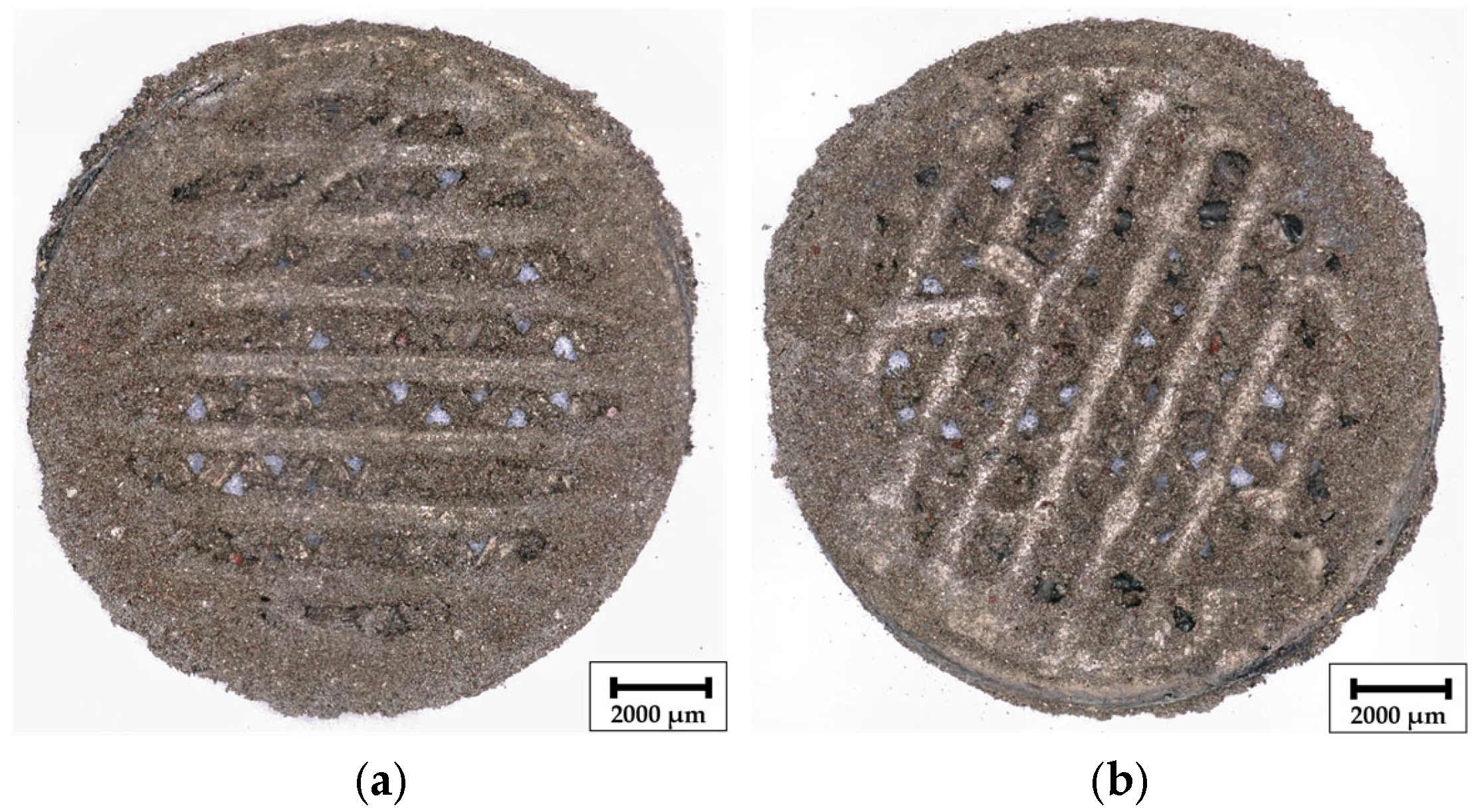
As shown in
Figure 4, digital light microscope panorama images at 30× magnification display the surface structure of manufactured composite Ni/S-PTh electrodes after the dissolution of the filling material. During coatings, side in
Figure 4a is positioned facing the Ni anodes and side in
Figure 4b faces the central axis of the rotating holder, resulting in potentially different local current density distributions during deposition. Unlike conventional Ni coatings, which typically display a bright metallic sheen, the surface of the composite electrode appears matte and brownish due to incorporation of S-PTh particles into the Ni matrix. The characteristic brown tone originates from the conjugated PTh layer, which not only improves sulfur dispersion and compatibility with the electrolyte but also alters the optical appearance of the composite layer [
33].
Both sides of the electrode, regardless of whether it is exposed to the anode or to the central cavity, exhibit a uniform distribution of functionalized sulfur particles, indicating successful particle suspension and consistent entrapment throughout the plating process. Such a uniformity suggests that the rotation of the holder, combined with the magnetic stirring, can effectively minimize the concentration gradients and support a symmetrical deposition of Ni and S-PTh, independent of the orientation.
These observations validate the compatibility of S-PTh particles with composite electroplating and confirm that the method enables uniform particle embedding and controlled microstructure, which is essential for a reproducible electrochemical performance.
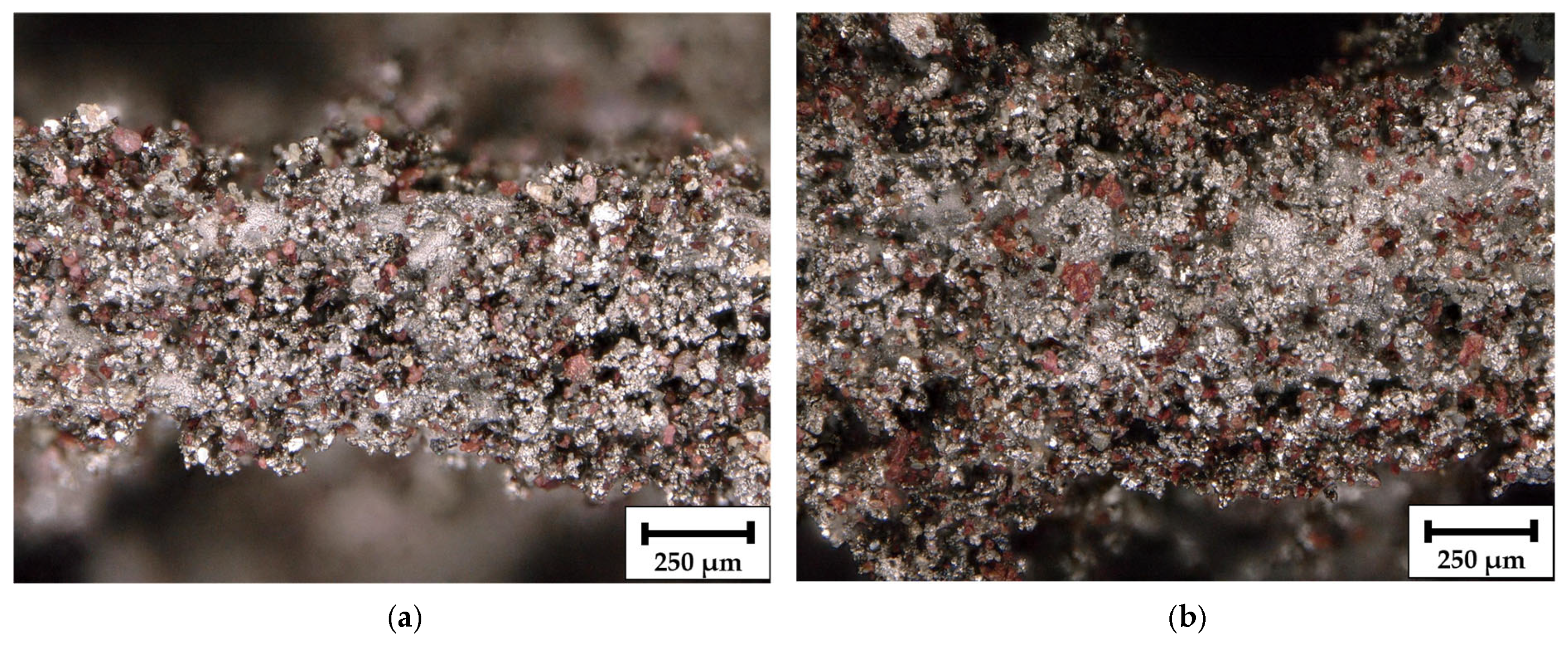
Figure 5 presents high-magnification digital light microscope images (200×) of individual struts from the porous Ni/S-PTh electrode, illustrating the surface morphology and particle distribution after composite electroplating.
Figure 5a corresponds to the surface oriented towards the nickel anodes, while
Figure 5b represents the surface facing inward towards the center of the rotating holder. In both views, brown-toned domains, attributed to S-PTh particles, are clearly embedded within the silvery metallic nickel matrix.
The Ni matrix does not grow as a smooth surface; rather, it forms buds. These buds indicate higher local current densities caused by geometrical inhomogeneities, which are also due to the lack of levelling additives; therefore, they are continuously reinforced. They may also originate from incorporated S-PTh particles.
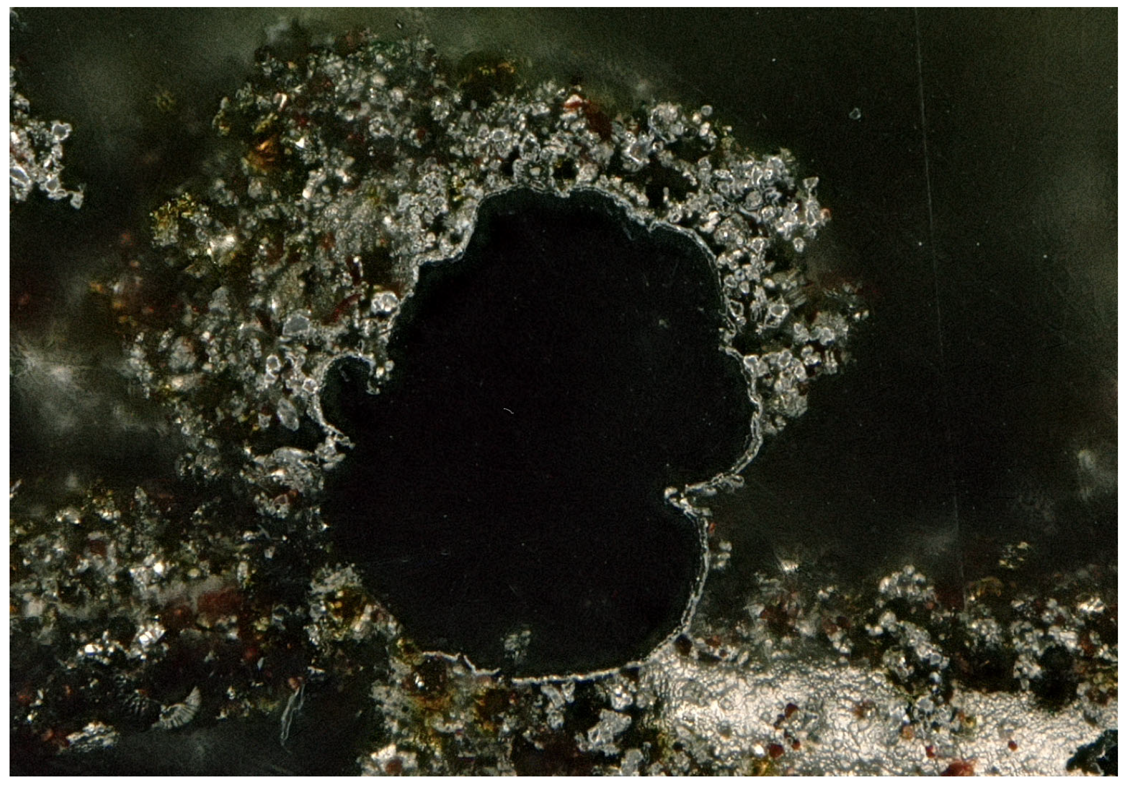
Figure 6 displays a digital light microscope cross-sectional image at 200× magnification of the Ni/S-PTh composite electrode. The image reveals the internal structure of the electrode after the template removal. The inner cavity is completely free of residual polymeric scaffolding, indicating the complete dissolution of the PVB-based 3D-printed support structure after the isopropanol treatment described earlier. This confirms that the sacrificial templating and the solvent removal process are successful in preserving the integrity of the porous nickel framework.
The black coloration on the inside of the hollow structure corresponds to the layer of conductive graphite applied to the polymer template prior to pulse plating. This layer, which facilitated electron conduction during the initial nickel deposition, remains partially adhered to the inner surface of the hollow structure, contributing to the contrast observed in the image. A distinct interface between two regions of different morphology and brightness is evident in the image. The inner compact layer, adjacent to the black cavity, corresponds to the pure nickel layer deposited by pulse plating. This region has a dense, uniform structure, which is typical of pulse-controlled nucleation and growth under low duty cycle conditions [
30]. The structure progresses beyond the compact nickel layer to a more porous, granular morphology, associated with the co-deposition of S-PTh particles. This outer layer displays a nodular-shaped structure and brownish embedded particles, confirming the incorporation of S-PTh particles into the metal matrix during the composite deposition step.
For electrochemical applications, such a layered structure, consisting of a mechanically stable nickel base layer and a high-surface-area composite outer layer, is advantageous. The compact inner nickel layer ensures good electrical contact and mechanical integrity, while the porous composite surface improves sulfur accessibility and electrolyte diffusion, which can improve cyclability when used in Li–S batteries.
3.2. Electrochemical Characterization of the Electrodes
To evaluate the electrochemical performance of the 3D-structured Ni/S-PTh composite cathodes, galvanostatic cycling measurements are conducted. Prior to the standard cycling, coulometric titration at a low current of 25 μA is performed in order to precisely quantify the electrochemically active mass in the absence of kinetics or mass transport constraints. Such a slow-rate activation procedure allows more lithiation of the sulfur and enables homogeneous wetting of the porous structure by the electrolyte. Based on the capacity provided during this titration step, the electrochemically active sulfur mass in the nickel matrix is calculated to be 4.7 mg.
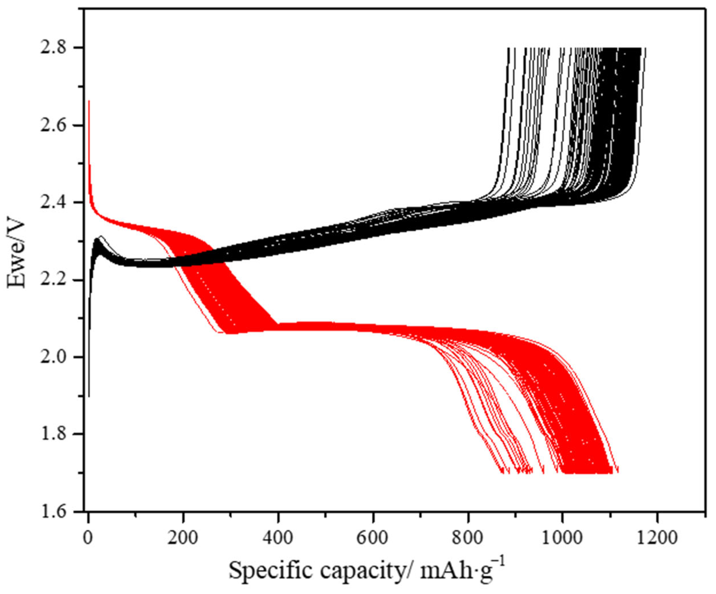
Figure 7 presents the galvanostatic charge–discharge voltage profiles of the 3D-structured Ni/S-PTh composite cathodes recorded during the first 200 cycles at a C/10 rate. The voltage profiles exhibit the two-step discharge plateaus characteristic of Li–S chemistry. The upper plateau at approximately 2.35 V vs. Li/Li
+ is associated with the reduction of elemental cyclic sulfur (S
8) to higher-order soluble polysulfides (Li
2S
6–Li
2S
4), while the lower plateau at approximately 2.05 V is associated with further reduction of these species to insoluble short-chain polysulfides and ultimately to Li
2S. The well-defined shape of the plateaus indicates the improved electrochemical accessibility of the sulfur and its homogeneous dispersion in the nickel matrix, as it benefits from the structural porosity of the electrode as well as the electronic percolation provided by the conducting skeleton.
The initial discharge capacity is approximately 1120 mAh·g−1. Such a high value confirms the effectiveness of the sulfur functionalization with PTh and the electrode architecture in enhancing active material accessibility.
Upon cycling, the voltage profiles are well maintained without any significant plateau position deviation or sloping trend, and the specific capacity stabilizes at about 910 mAh·g−1 even after 200 cycles with a capacity retention of ~81%. This stability indicates the great mechanical integrity of the Ni matrix. The very low capacity fade and maintained plateau morphology throughout cycling also indicate uniform dispersion and the electrochemical integration of the functionalized sulfur particles in the network of nickel.
All in all, the findings in the present study confirm that the composite electroplating method produces structurally and electrochemically stable cathodes. The combination of pulse-plated nickel scaffolding, the homogeneous S-PTh embedding, and the binder-free design results in an outstanding cycling stability and performance.
4. Conclusions
In the present work, a novel manufacturing method for porous, binder-free Ni/S-PTh composite cathodes for Li–S batteries is created and demonstrated to be effective, enabling precise control of the electrode architecture while avoiding high-temperature processes and toxic chemicals. A sacrificial polymer template is 3D printed, then coated with a graphite-based conductive layer followed by the deposition of nickel via pulse electroplating to form a homogeneous and dense nickel scaffold. S-PTh particles are co-deposited into the growing metal matrix by a second low-temperature composite electrodeposition process. Upon dissolution of the polymer template, a mechanically stable porous Ni/S-PTh electrode architecture is obtained.
A detailed morphological characterization by digital light microscopy confirmed complete elimination of the inner polymeric support and homogenous dispersion of sulfur within the porous matrix. Cross-section imaging distinguished the dense pulse-plated nickel underlayer from the more nodular, sulfur-rich composite outer layer.
Electrochemical evaluation by galvanostatic cycling at C/10 revealed an initial discharge capacity of approximately 1120 mAh·g−1, a stabilized capacity of ~910 mAh·g−1 after 200 cycles, and a capacity retention of ~81%. The Li–S battery characteristic plateaus are preserved, confirming the electrochemical accessibility of sulfur and the structural stability of the electrode. These results attest to the electrochemical efficiency of Ni/S-PTh composite architecture and emphasize the advantages of PTh functionalization for minimizing capacity fade and the polysulfide shuttle effect.
