Article

Influence of Lithium Plating on the Mechanical Properties of Automotive High-Energy Pouch Batteries

by
Syed Muhammad Abbas
1,*,
Gregor Gstrein
1,*,
Alois David Jauernig
1,2,
Alexander Schmid
1,2,
Emanuele Michelini
1,2,
Michael Hinterberger
3 and
Christian Ellersdorfer
1,2
1
Vehicle Safety Institute, Graz University of Technology, 8010 Graz, Austria
2
Battery4Life GbmH, Inffeldgasse 13/6, 8010 Graz, Austria
3
AUDI AG, 85057 Ingolstadt, Germany
*
Authors to whom correspondence should be addressed.
Batteries 2025, 11(9), 330; https://doi.org/10.3390/batteries11090330
Submission received: 16 July 2025 / Revised: 29 August 2025 / Accepted: 30 August 2025 / Published: 3 September 2025
(This article belongs to the Collection Feature Papers in Batteries)

Abstract

Lithium plating (LP), as a specific degradation mechanism in lithium-ion batteries (LIBs), has been thoroughly investigated regarding formation conditions and potential safety hazards, but it is yet unknown how this effect influences the mechanical properties of batteries in the case of mechanical deformation. To address this issue, pouch cells used in EVs were artificially aged (AA) to a state of health of 80–82% in conditions that predominantly cause the formation of LP. These cells were subjected to a mechanical abuse load, and safety-relevant parameters, such as tolerated deformation level, failure force, and the process of thermal runaway (TR), were analyzed and compared with respective fresh (F) and aged cells of the same type. Complementary microscopy analyses were carried out to compare the found changed mechanical response with the different layer morphology caused by LP. The tests did exhibit a significantly different mechanical response of cells in the three states but also clearly altered short-circuiting behavior. The tolerated peak force at discharge state dropped by −28% and at charge state by −37% compared to fresh cells, while the deformation at failure slightly increased by +6% for the AA cells. A clear reduction in stiffness (−16%) of the LP cells was attributed to the formed layer, identified as mossy LP. The significantly stronger voltage drop at failure, seen for the LP cells, was associated with severe exothermal reactions of LP in contact with air and moisture during TR. This study revealed the strong influence of LP on the mechanical properties of LIBs. However, the transferability of the findings to other cell chemistries or formats is unclear, emphasizing the need for further investigations in this research field.

Graphical Abstract

1. Introduction

Lithium-ion batteries (LIBs) are currently at the forefront as an alternative fuel/power source for automobiles, aiming to replace fossil fuels. Extensive research and development efforts, both past and ongoing, have been directed towards improving their energy density and cycle life [1,2]. The consumer application of LIBs was predicted to increase [2] in a variety of applications, which highlights the demand for the safety and performance improvement of LIBs. Thus, mobile applications are considered particularly safety-critical due to their high energy density and size, especially in electric vehicles (EVs), plug-in hybrids (PHEVs), and hybrid vehicles (HEVs).
The performance of LIBs fades over the operational lifetime, which is referred to as aging or electrochemical degradation [3]. Different degradation mechanisms have been identified, categorized as the loss of lithium inventory (LLI), the loss of anode-active material (LAMNE), and the loss of cathode-active material (LAMPE) [4]. Lithium plating (LP), the specific degradation mode that is the focus of this study, falls under the LLI category. LP occurs during charging under particular conditions, such as high charging currents, low temperatures, high localized pressures, and elevated states of charge (SOCs) [5,6,7,8,9,10,11]. During such conditions that retard the diffusion of the lithium (Li) ions into the anode structure, high local concentrations of lithium ions on the anode surface lead to the polarization of the anode and the formation of metallic Li. This drops the anode voltage below 0 V vs. Li+/Li [12,13] and mossy or dendritic LP form [5,6] on the anode surface instead of Li intercalating into the active material. Unfavorable combinations of the indicated conditions can lead to LP, even if the single factors are still in “normal” operation conditions. This is considered a safety-critical aging mechanism, as the reaction of the electrolyte with plated lithium leads to electrolyte decomposition and gas formation [14]. Additionally, the dendritic growth of lithium can puncture the separator and cause internal short circuits [15,16,17], and the non-uniform growth of an additional metallic layer on the electrode surface can result in the formation of degradation hot-spots that lead to greater safety risk.
Already, a number of studies have reported that during the operational lifetime, along with the capacity fade, a significant change in safety and mechanical properties of LIBs occurs [18,19,20,21,22,23]. These changes are highly relevant for the behavior in the case of a crash of an electric vehicle, where damage and deformation to LIBs can cause short circuits, which can lead to fire as a result of thermal runaway (TR) [24,25,26,27]. Several studies have been conducted on the change in the mechanical properties of fresh and aged pouch cells under different impact loads and velocities [18,19,20,28,29,30,31]. Kovachev et al. [18] investigated the mechanical properties of 41 Ah graphite/NMC-LMO pouch cells that were artificially aged (AA) for 700 cycles. Quasi-static cylindrical indentation tests at 100% SOC revealed an increased failure force and displacement for aged cells compared to fresh cells. The study attributed the findings to an increase in the thickness of the solid–electrolyte interface (SEI) layer and the consumption of electrolyte, leading to dried-out regions in the cell. Sprenger et al. [19] also investigated pouch cells (nominal capacity of 74 Ah and graphite/NMC chemistry) that were artificially aged based on a real driving profile until 90% state of health (SOHc). Quasi-static cylindrical indentation tests at 0% and 100% SOC showed that aged cells failed at lower forces and higher displacements compared to fresh cells, particularly at 0% SOC. The findings were attributed to stresses induced by decomposition products and reduced mechanical strength of the separator. In a different study conducted by Sprenger et al. [20], decreased cell stiffness, reduced failure force, and an increase in failure displacement were related to SEI thickness increase and anisotropic failure behavior of the anode and separator layers. Liu et al. [32] investigated 25 Ah graphite/NMC pouch cells at 25% SOC under quasi-static spherical indentation. The cells were artificially aged to SOHc 90%, 80%, and 70% under generic cycles at 0 °C. The result was a shift in the failure displacement to higher values for aged as compared to fresh cells, and the failure force remained similar. The findings were attributed to shear fracture behavior of the cell and the compression properties of anode, which failed at higher displacements as the aging increased.
This study investigates the specific aging mechanism of LP and its impact on the behavior of LIBs under mechanical abuse conditions. LP is regarded as a highly relevant degradation pathway [33,34], despite occurring only under certain operational conditions. A typical scenario for LP formation is fast charging at low temperatures, such as during winter operation. To mitigate this risk, battery thermal management systems monitor pack-level cell temperatures and limit charging currents when temperatures are too low [35,36]. However, not all individual cells within a pack are monitored [37], and sensor malfunctions may occur, potentially allowing the boundary conditions (BCs) for LP formation to be met.
LP is suspected to alter the mechanical properties of LIBs, as lithium deposits form inhomogeneous metallic layers on the anode surface, likely modifying the interactions between electrode stack components under mechanical load. In addition, due to its high chemical reactivity, LP represents a considerable safety hazard: contact with air or humidity during an electrical short circuit can trigger severe exothermic reactions.
A review of the literature reveals a significant lack of studies addressing the mechanical properties of aged pouch cells exhibiting LP. One reason for this gap is that LP forms predominantly during charging but can partially dissolve during discharge [33,38,39], which introduces substantial challenges for reliable characterization:
  • First of all, the presence of LP must be confirmed beforehand, which requires a determination of the operational conditions under which LP forms must first be determined for the cells under study. Verification can be achieved indirectly through voltage and current signal analysis during charging, discharging, or relaxation phases, or directly via post-mortem analytical methods, as demonstrated in our previous work [40,41].
  • It is in principle, Without disassembling the cell, the exact location of LP formation remains unclear, as it depends on pressure variations within the electrode stack, current density distribution, temperature, and C-rate [7,42,43]. These factors must be considered when defining the shape of the impactor and the location of mechanical loading in abuse tests.
  • LP partially dissolves during discharge [33,38,39]. Therefore, post-mortem analysis requires cells to be opened in a fully charged state, which poses considerable safety risks in high-capacity automotive cells. In contrast, analysis of discharged cells only provides indirect and limited insights.
  • LP forms and dissolves throughout the operational cycle [33]. Even in fully charged state, the plated lithium content does not remain constant after charging is complete, complicating efforts to establish repeatable and robust characterization.
In this study, we aimed to overcome these challenges and address the identified knowledge gaps. Specifically, LP was first identified in commercial high-energy pouch cells (nominal capacity: 64.6 Ah; cell chemistry: graphite-SiOx/NMC 712) using non-destructive electrochemical analysis during cycling, as detailed in [40]. Subsequently, LP formation on the anode was confirmed through post-mortem analysis [41]. The relationship between this prior work and the present investigation is illustrated in Figure 1. For the current study, cells were cycled under LP inducing BCs until the SOHc dropped below 85%. These cells are referred to as AA. The SOHc was calculated based on the nominal capacity of the fresh (F) cells. Quasi-static cylindrical indentation tests were then applied to both fully charged and discharged cells, and the mechanical properties of AA cells were compared with those of F and real-aged (RA) cells.

2. Materials and Methods

To address the aforementioned challenges, a research approach was designed to (i) identify the boundary conditions (BCs) leading to LP formation in the tested cells, (ii) confirm the presence and localization of LP, and (iii) quantify its influence on the mechanical properties of LIBs. Figure 1 outlines this workflow; the steps targeted in the present study are highlighted and enclosed by a boundary. Figure 1 also indicates how F, RA, and AA cell groups were employed during the investigations.
In this study, fresh graphite–SiOx/NMC pouch cells with a nominal capacity of 64.4 Ah and dimensions of 354 mm × 101 mm × 11.25 mm (L × W × H), were used as in our previous studies [40,41]. These served as the baseline for comparison with AA cells (artificially aged under LP-inducing BCs) and RA cells of the same type. The RA cells were operated in a vehicle according to a test-track protocol, representing a typical driving distance of 160,000 km [44]. Table 1 summarizes the analyzed cell groups, their nomenclature as used in the results, and their respective states.
The AA cells were cycled under controlled conditions to induce LP as the predominant degradation mode. Cycling was performed at a constant cell temperature of 10 °C with a charging C-rate of 1.5 C. The constant temperature of 10 °C is considered the main accelerating factor of the degradation. To reach a capacity fade of approximately 18–20% (considered “close” to the end of life), 20 consecutive constant current-constant voltage (CC-CV) cycles were performed between SOC 0% and 90%. The presence of LP was confirmed through non-destructive methods [40] and selected post-mortem analytical techniques [41]. Detailed BCs and cycling protocols are provided in our previous studies [40,41].
LP is more likely to form in regions subjected to elevated surface pressure, as shown from Fuchs et al. and others [7,9,11]. This effect was exploited by placing a cathode sheet impactor (thickness: 142 µm) at the center of the cell surface. During cycling, a nominal pre-tension force of 300 N is uniformly applied across the entire cell; however, beneath the area of the impactor, the local pressure was amplified by a factor of approximately 23, thereby creating a region with a high probability of LP formation. For later experiments, the impactor shape was modified from circular to rectangular while keeping the contact area constant, thereby maintaining the same pressure amplification.
The mechanical behavior of the described AA cells was compared with identical cells taken from a battery pack operated in a test vehicle for >160,000 km. The vehicle followed a representative driving profile, and the cells retained approximately 93% residual capacity. A detailed comparison of the mechanical response of fresh and RA cells, including degradation mechanisms at the cell-component level, is provided in a separate study [44].
Due to differences in degradation state, the analyzed cells exhibited varying thicknesses. Prior to mechanical abuse testing, the thickness of each cell was measured using a Vernier caliper in both the discharged and fully charged states.
The primary objective of this study was to assess the influence of LP on the mechanical properties of LIBs, with particular attention to safety-relevant characteristics such as tolerable load, deformation before failure, and short-circuit behavior. To this end, quasi-static indentation tests were performed to simulate mechanical abuse scenarios representative of EV crash conditions.
These tests were conducted in the Battery Safety Center Graz (BSCG) at TU Graz, using an in-house built hydraulic press with a maximum force of 420 kN. This test rig features a displacement measurement system (linear glass scale encoder) with an accuracy of ±1 µm. The indentation force is measured using a GTM Series K 500 kN load cell (GTM Testing and Metrology GmbH, Bickenbach, Germany) and recorded by NI-9237 Bridge input module (National Instruments, Austin, TX, USA) with 2 kHz sampling frequency. Moreover, the cell voltage was recorded by NI-9229 voltage module (National Instruments, Austin, TX, USA) in order to detect cell failure during the test. The described test bed was already used and described in detail in the studies conducted by Kovachev et al. [18] and Sprenger et al. [20] for quasi-static indentation tests of pouch cells. The SOC 100% quasi-static results of F cells used as a reference in this study were already published by Schmid et al. [45].
The test setup for this study is illustrated in Figure 2a,b. A cylindrical steel impactor 30 mm diameter × 70 mm in length, with edges rounded to 5 mm radius was used for the quasi-static tests. This impactor was used to exclude the cell edges from deformation [45]. The cells were tested along the long side of the cell, and the impactor was positioned in the center of the cell (localized pressure area). The cells were mounted on a 20 mm steel plate, placed on the bottom plate of the test bed, and an insulating 3 mm Pertinax® sheet (Dr. Dietrich Mueller GmbH, Ahlhorn, Germany) was placed between the cell and steel plate, to avoid a short circuit with the test bed. The indentation speed was 1 mm/s and test were performed at ambient temperature (22–25 °C). The abort criterion was set to 8 mm indentation depth (equivalent to approximately 60% of the cell thickness) to ensure the complete failure of the cells.
For each cell type (F, RA, and AA) three test repetitions were carried out at 0% SOC and 100% SOC. In order to compensate for the different initial thicknesses of the cells in the experiments and to achieve a good repeatability of the initial force onset, the point of contact was set, when a force of 500 N was reached.
The analysis focused on differences in the mechanical response during load application, the peak force and corresponding cell deformation, and the compression stiffness. Stiffness was determined in the linear region of the force–displacement curve between 15 kN and 25 kN. In addition, the depth of the voltage drop at failure was monitored and compared across cell types to assess differences in short-circuit behavior.
Observed differences in the mechanical behavior of F and aged cells should be justified by means of a subsequent post-mortem analysis of the cells. Therefore, cells were discharged to SOC 0% and dissected inside a glove box in an inert (argon) atmosphere instantly after cycling. The cells were dissected at 0% SOC for the safety of the personnel and glove box in an event of short circuit. Firstly, a layer-wise visual inspection was carried out to identify traces of LP. In this study, particular attention is drawn to morphology differences between the differently aged anodes, subsequently samples were examined through field emission scanning electron microscopy (FESEM). It was considered to be important to also highlight the differences in morphology of SEI layer (RA cell) and LP in order to conclude on different mechanical properties of the AA cells. Further detailed post-mortem analysis including inductively coupled plasma optical emission spectroscopy (ICP-OES), nuclear magnetic resonance spectroscopy (NMR) and scanning electron microscopy (SEM), has already been conducted in our previous study [41] to verify the presence of LP in the AA cells and to highlight differences to the F and RA cell’s anode samples. SEM analysis are described in detail in our separate study [41].

3. Results

A total of 18 indentation tests were performed on cells at varying degradation states to investigate the influence of LP on the mechanical properties of LIBs under mechanical abuse conditions. The focus of the analysis was to assess the effect of LP by comparing the mechanical behavior to that of F cells. Results from these tests, complemented by post-mortem analyses to explain the observed behavior are presented below, beginning with cell thickness measurements.
During cycling under LP conditions, the AA cells showed a significant increase in thickness compared with F cells, as shown in Table 2. The irreversible thickness increase (also referred to as “swelling”) of AA cells amounts for 9.1% and the thickness gain during charging the cell from discharged to fully charged state (also referred to as “breathing”) slightly reduced from 4.4% to 3.7% in comparison with the F cell’s results. Significantly less swelling (+4.7%) was observed for the analyzed RA cells, which was expected given the higher SOHc.
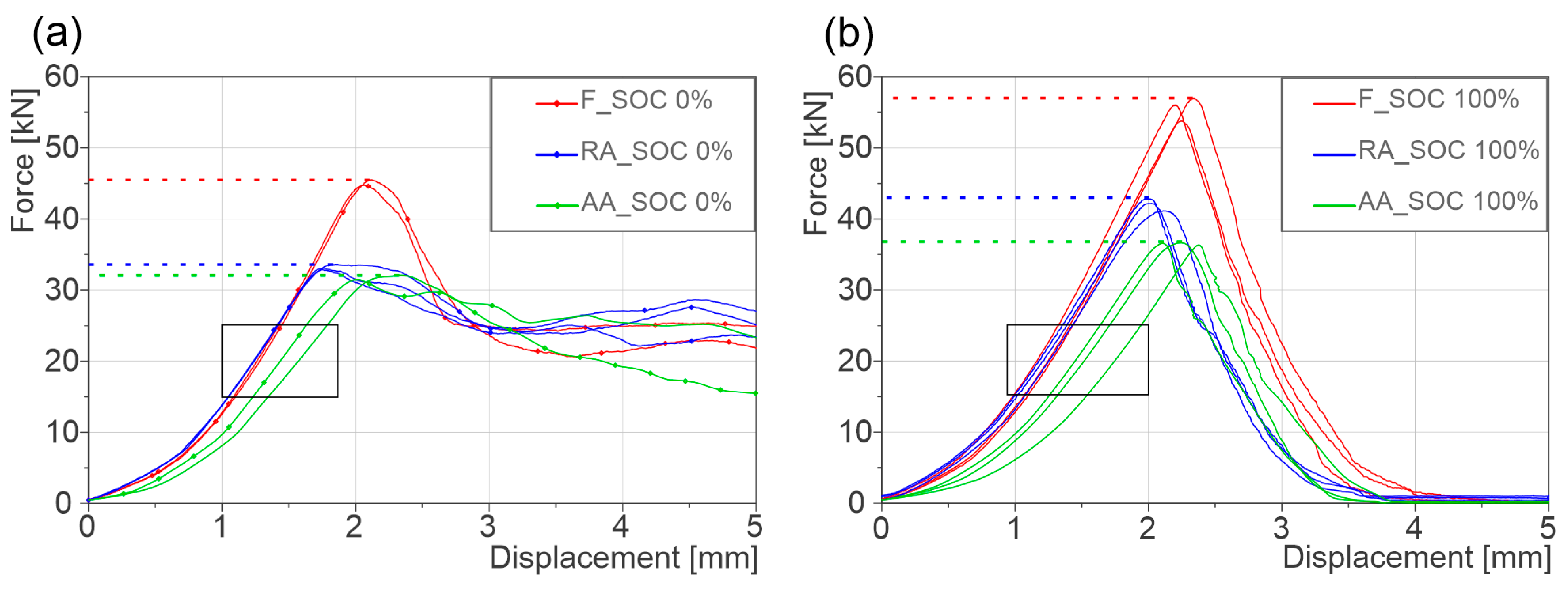
When subjected to the defined abusive mechanical loading, the cells in different degradation states showed significantly different mechanical responses. However, independent of the charge state of the examined cells, the failure of the cells is indicated by a clear drop in the cell voltage signal, coincided with the observed peak force. From Figure 3a, it can be seen that F cells at 0% SOC fail at approximately 45 kN indentation force, whereas for AA cells fail at approximately 32 kN, which is a significant reduction of about −28%. The indentation depth at failure increases slightly (+0.14 mm, +6%) for the AA cells as compared with respect to the F cell. For the analyzed RA cells, a similar drop of failure force (−12 kN, −26%) is observed, whereas in this case, the deformation at failure significantly reduces by −0.31 mm, representing a drop of approximately −15%. After the failure of the cell short circuit within cell layup due to the direct electrical contact of cell components—the captured force level settles at about 25 kN. For the tested discharged cells, the damaged structure still provides resistance to the applied force at higher deformation levels (exceeding failure deformation), with no clear differences for all the analyzed cells. However, the force drop at failure was found to be much more prominent for the F cells in comparison with both type of aged cells. In the series of tests with discharged cells, two results had to be excluded as outliers, as they did show clearly differing characteristics compared to the remaining cells at same state, which, in general, did show a good reproducibility.
Quasi-static compression results at 100% SOC are shown in Figure 3b. In a fully charged state, F cells failed at a peak force of approximately 57 kN, with t corresponding to an intrusion depth of 2.24 mm. The AA cells failed at similar intrusion depths, although at significantly lower intrusion forces (−21 kN, −37%). The examined RA cells exhibited a reduction in tolerable peak force of about −15 kN (−26%) as compared to the respective F cells and failed at slightly lower intrusion of about 0.2 mm (−11%). In contrast to the discharged cells, at 100% SOC all the cells undergo TR at failure and the cell structure is destroyed completely, resulting in a drop of force to 0 kN after failure. Table 3 shows average failure force and displacement values at different SOC levels, comparison to F cell is also provided.
In addition to the change in the peak tolerable forces and deformation, a significant reduction in stiffness of the AA cells is observed in comparison to F cells, highlighted in the black rectangles in Figure 3a,b. The stiffness is calculated between 15 kN and 25 kN. The stiffness of the AA cells decreased by 16% at 0% SOC and by 13.5% at 100% SOC, in comparison to F cells. Similar tendencies were also observed for the examined RA cells. The respective average stiffness values as well as the changes relative to the F cells are shown in Table 4.
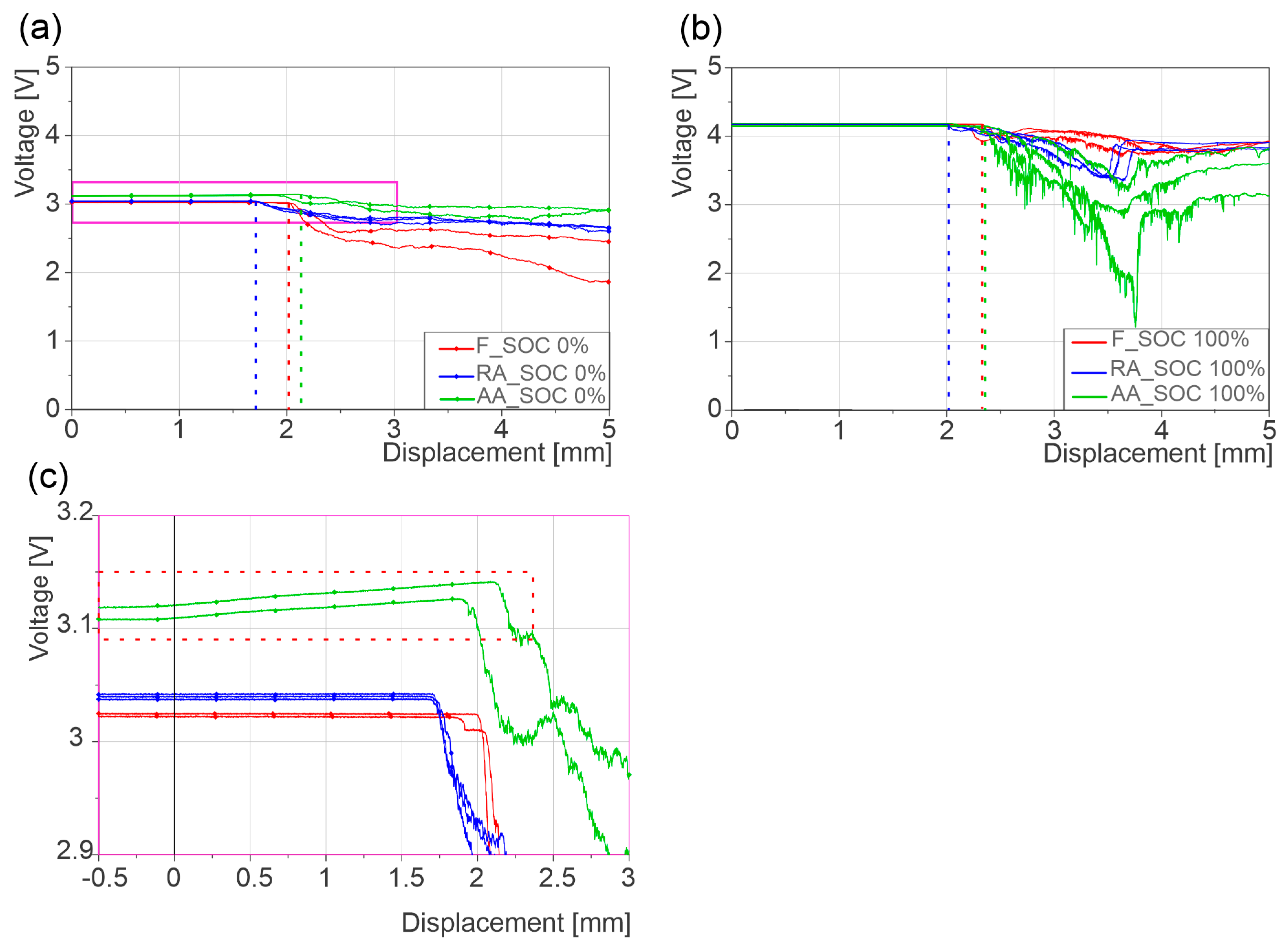
During the mechanical abuse tests, the voltage drop associated with internal short circuit (ISC) coincided with the failure force of the cells, consistent with previously reported in the literature [14,18,19,20,28,30]. In discharged state, the RA and AA cells exhibited a more gradual and lower voltage drop at failure in comparison with the respective F cells, which fail instantaneously, Figure 4a. In contrast, fully charged AA cells showed a drastic voltage collapse relative to both F and RA cells (Figure 4b). However, fully charged F cells also displayed an abrupt voltage drop, although less severe than that of AA cells. It was also observed that the voltage of RA and AA cells recovers partly after dropping initially, as seen in Figure 4b. Particular attention is drawn to a slight increase in the cell voltage of the AA cells at 0% SOC during the loading phase until the failure point is reached, as shown in Figure 4c.
To understand and justify the observed differences in behavior at the cell level, complementary post-mortem analyses were carried out. This was undertaken for the following reasons: firstly, to confirm the presence of LP in the tested regions, as reported in [41], and secondly, to identify morphological differences on the anode surfaces of the AA cells as a result of LP. The analysis focuses exclusively on the anodes, as LP occurs on this electrode.
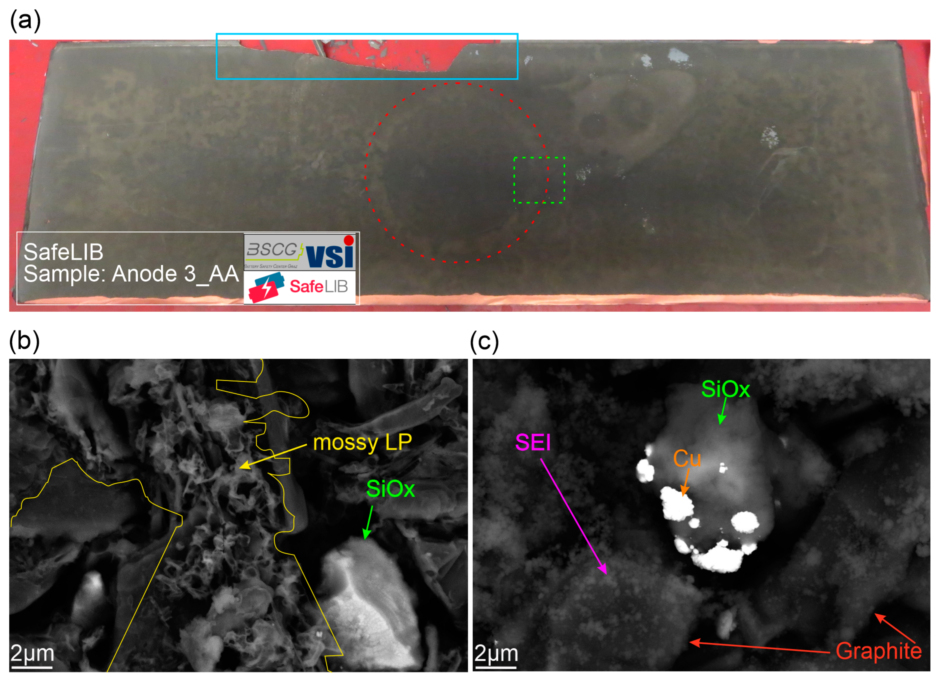
The visual inspection of the AA cells under an inert atmosphere (Figure 5a) revealed randomly distributed light gray areas on the anode surfaces, as well as a ring-shaped light gray area at the boundaries of the impactor at the center of the layer. These regions are identified as LP in our previous work [41] and also in other studies [7,43]. Furthermore, the partial delamination of the anode active material from the current collector was observed at the layer boundaries. This effect was similarly observed for the RA cells as well as the F cells.
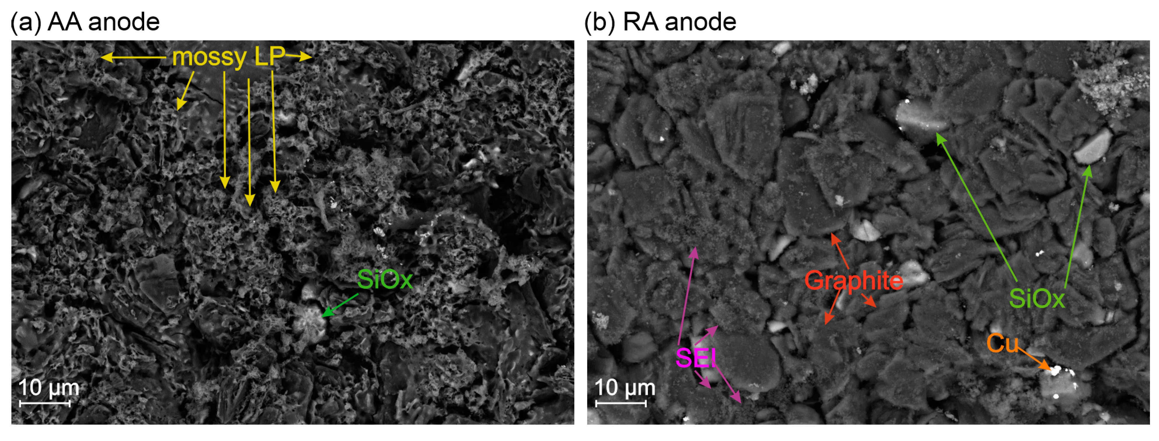
To examine the surface morphology, high-magnification SEM backscattered electron images were obtained from samples of the F, RA, and AA cells. Significant differences were observed, in particular for the AA cells exhibiting LP, as shown in Figure 5b,c. In Figure 5b, the AA anode exhibits an additional layer (enclosed in the yellow lines) on top of the graphite particles. This layer exhibited a mossy or sponge-like structure with numerous voids, consistent with descriptions in [46,47,48,49]. This layer can be found randomly distributed over the surface of the AA anode and was identified as LP in [41]. However, since Li itself cannot be visualized in SEM, the visual appearance in the figure only represents reaction products of Li (mainly with oxygen and fluorine). No comparable layer was observed on the RA anode, as seen in Figure 5c. Here a granular layer on the graphite particles was seen, which was identified as SEI layer [50,51]. Additionally, copper (Cu) deposits were detected, although their origin remains unclear, as no corrosion of the current collector was evident [44]. For overview of the surface morphology, lower magnification SEM images are provided in Appendix A.

4. Discussion

Based on the results of the conducted cell tests, it was demonstrated that LP as specific degradation mechanism, significantly influenced the mechanical properties of a cell when subjected to a deformation load. When compared to differently aged cells (RA) of the same type, partly similar but in some cases contrasting behavior was observed, emphasizing the significant role of the aging history. In the following section, different aspects of these results are discussed in detail.
In recent studies, there is no clear trend regarding the dependence of the SOC on the tolerable peak forces in mechanical abuse [18,19,20,30]. In these studies, the failure behavior was attributed to SEI layer thickness, whereas no clear relation between failure force and SOC was reported. In the present study, in which F cells are compared with two differently aged cells of the same type, the SOC dependence varies significantly among the analyzed cells. At 100% SOC in Figure 3b, the observed peak force increases by approx. 12 kN (+27%) for the F cells but only by about 2 kN (+6%) for the AA LP cells. For the analyzed RA cells, the increase of approx. 8 kN (+24%) is still comparable to the respective F samples. This indicates that the SOC dependency of the peak force is influenced by the predominant degradation mode, such as LP in the case of the AA cell. It is likely also influenced by the SOHc; lower SOHc cells exhibit a weak dependency of peak force on SOC of the cell, and thus, lower peak force increases for RA and almost negligible peak force increases for AA at 100% SOC. The analyzed RA cells retained high residual capacity (93% SOHc) in contrast to the AA LP cells that were close to end of life (80–82% SOHc).
For the discharged cells, a different mechanical response is seen for the F cells in comparison with both aged cells. The F cell’s reaction force drops instantaneously after failure for about −44% with an observable peak (see red curve in Figure 3a). In comparison to the aged samples, the F cells show a much more pronounced brittle behavior at failure in discharged state. Due to the complete disintegration of the cell material during the ISC and TR, this difference is not observed for the fully charged cells, see Figure 3b.
A right shift in force–deflection curves is frequently described in studies with focus on the influence of aging of LIBs on their mechanical properties. In the literature, this effect is typically attributed to an increase in cell thickness as a result of SEI growth, which is reported to be “soft” in comparison with the other cell components [18,19,20,32]. In addition, a generally higher degree of degradation effects among the layered cell components causes softer behavior and larger failure displacements. For the AA LP cells, this right shift is observed in both charged and discharged state. The microscopic analysis of the cell surfaces, however, indicates that this effect is primarily caused by the additional mossy Li layer, as no traces of SEI were detected. Studies [46,52] have shown that such a mossy Li layer has significantly lower stiffness than the other components in the cell layup (except for the separator [53]). Young’s modulus of the mossy Li layer is approximately 1.5–3 GPa, compared with 200 GPa for NMC and 11.5 GPa for graphite. During indentation, initially the soft mossy Li is compressed until it is fully compacted. At further deformation, the material response is comparable to the F cells. The reduced stiffness, shown in Table 4, is likely related to further degradation modes present in the cell. In contrast to the analyzed LP cells and to prior studies, the RA cells do not show such a right shift in the mechanical response. As described in detail in [44], this is most likely related to the high SOHc and the low thickness increase, observed for those RA cells.
In [44], particle cracking in the cathode active material (NMC) was identified as the primary mechanism underlying the significantly lower failure force of the analyzed RA cells. Whereas the onset of the reaction forces is clearly different for the RA and the AA cells showing LP (right-shift in the force–deflection curve), the respective peak forces are quite comparable. Which supports the hypothesis, that the underlying degradation mode for this reduction in failure force could be the same in both types of aged cell. For the present study, the conclusions are drawn based on the findings and similarities compared with [44]; however, there is no experimental proof. When metallic Li plates on the anode under specific operational conditions (as described earlier), at the same time the cathode becomes increasingly de-lithiated. Literature shows that the de-lithiation of NMC induce phase changes [54], which promote the nucleation and propagation of particle cracks [55]. Therefore, it is highly likely that, similarly to RA cells, cracked NMC particles are the main contributor to the lower tolerated indentation force in AA cells. The similarity in the behavior of the same cells with a different aging history and the contrast to other studies [18,19,32] suggests a particular characteristic of the analyzed cell. This consideration is further elaborated in [44].
The voltage response of the LP cells during mechanical deformation exhibits additional distinctive features, partly consistent with the trends observed in RA vs. F cells but also showing significant deviations. An increase in the cell voltage of approximately 20 mV during the progressing deformation, as seen Figure 4c, was observed only for the AA cells at 0% SOC. This effect is attributed to the formation of a low resistance path in LP regions on the anode, resulting in the reduction in internal resistance of the cell, due to the compression of the conductive mossy Li under pressure from initial contact. Also, it has to be noted that since the thickness of the AA cells increased in comparison to fresh and RA cells, it can also be assumed that the contact between the layers is poor at 0% SOC in AA due to increased thickness, and under this initial contact pressure the inter layer contact improves, leading to increase in the observed voltage increase in AA cells.
Another finding of the analysis of the cell voltage during the mechanical abuse is the instantaneous voltage drop of the F cells, as seen in Figure 4c. This further supports the assumption of the more brittle F cells, which is derived on basis of the force–deflection data in Figure 3a. At 100% SOC (Figure 4b), the voltage drop at ISC is considerably stronger for both RA and AA cells in comparison to F cells, which is in agreement with results in the literature [18,19,20,32]. However, it is obvious that for the AA cells, the voltage drop at failure is significantly more pronounced, which is attributed to the highly chemically reactive metallic Li, present in these cells. The partial recovery of the voltage after initial voltage drop of RA and AA cells can be attributed to breaking away of the short-circuited components in the deformation area in the course of the TR, which leads to the observed increase in voltage. However, this effect is transient, as the subsequent stages of TR ultimately lead to complete cell failure and combustion. At discharged state (0% SOC), the ISC did not result in a TR, and no ambient air could come into contact with the cell components due to the intact pouch. The absence of TR at 0% SOC can be attributed both to the low energy content of the discharged cells, which is insufficient to trigger thermal runaway, and to the intact pouch, which prevents contact between reactive components and ambient air. Consequently, the violent reactions observed at higher SOC are not present under these conditions. The more abrupt voltage drop of F cells at both SOC 0% and 100% is consistent with their lower internal resistance compared with aged cells, which exhibit a more gradual decline.
The mechanical integrity of the cells was significantly compromised by LP formation (AA cells). The force required to induce complete failure was significantly reduced, and the ISC voltage drop was steeper in the presence of LP, rendering the cells more safety-critical compared with F cells of the same type. This study provides valuable information and complementary insights into the effect of LP on the mechanical integrity of LIBs; however, several limitations must be acknowledged. First, only one type of cell chemistry was investigated in this study. While the used NMC cathode material has been widely studied in comparable research, the graphite/SiOx anode material is a distinctive feature of these cells. The specific influence of SiOx on LP was not yet analyzed in detail. Second, the presence of mossy LP was confirmed only indirectly by SEM at 0% SOC, as discussed in previous study [41]. It is there for unclear, if the morphology of LP, as observed for discharged cells is same for fully charged cells. Finally, prior studies [39,47,56] have demonstrated that LP can also grow as dendrites, depending on the operational BCs, rather than the mossy morphology identified here. Consequently, the findings of this work should not be directly generalized for other cell chemistries or operational conditions.

5. Conclusions

The aim of this study was to investigate the safety relevance of lithium plating (LP), as specific aging mechanism in lithium-ion batteries (LIBs) under mechanical abuse conditions. Although this degradation mode has been extensively studied in experimental cells, a significant knowledge gap remains regarding its impact on the mechanical properties of commercial high-energy-density LIBs. Addressing this gap is challenging, particularly due to the need to confirm both the presence and the localization of LP in cells subjected to mechanical characterization.
In our previous work, the operational boundary conditions (BCs) leading to LP in the investigated cell type, as well as its transient behavior and localization, were verified using non-destructive electrochemical techniques [40] and analytical methods [41]. Based on this previous research work, cells were AA under LP inducing BCs and subjected to mechanical abuse loads. The results were compared with fresh (F) cells as well as same cells used in a car for 160,000 km [44].
The findings demonstrate that LP significantly affects the mechanical properties of LIBs. Compared with F cells, LP-aged cells exhibited a pronounced reduction in tolerable force, which is attributed to cracking of NMC particles in the cathode. This process likely occurs during LP formation, leading to a loss of lithium inventory (LLI). Furthermore, LP-aged cells displayed a substantial increase in thickness, resulting from the growth of mossy lithium layers, indirectly confirmed through microscopic imaging. These morphological changes corresponded to a marked reduction in cell stiffness, as reflected by a rightward shift in the force–deflection response along the thickness direction. The observed effects were consistent in both charged and discharged states.
In addition, LP altered the internal short circuit (ISC) behavior when cells were loaded for failure. LP aged cells exhibited more pronounced voltage drops, likely due to severe exothermic reactions between metallic lithium, cell components, and ambient air once the casing ruptured.
Overall, LIBs exhibiting LP showed a more critical safety response compared with fresh cells of the same type. These results highlight two key implications: (i) the importance of robust thermal management systems in automotive applications to prevent LP formation by maintaining optimal operating conditions, and (ii) the necessity of further research on the effects of aging mechanisms on the safety relevant properties of LIBs.

Author Contributions

Conceptualization, S.M.A. and G.G.; methodology, S.M.A. and G.G.; software, S.M.A.; validation, S.M.A., G.G. and A.D.J.; formal analysis, S.M.A. and G.G.; investigation, S.M.A. and A.D.J.; resources, S.M.A.; data curation, S.M.A.; writing—original draft preparation, S.M.A.; writing—review and editing, S.M.A., G.G., A.D.J., A.S., E.M., M.H. and C.E.; visualization, S.M.A.; supervision, G.G.; project administration, G.G. and C.E.; funding acquisition, C.E. All authors have read and agreed to the published version of the manuscript.

Funding

This work originates from the research project SafeLIB. The COMET Project SafeLIB is funded within the framework of COMET—Competence Centers for Excellent Technologies (grant agreement no. 882506) by BMK, BMDW, the Province of Upper Austria, the province of Styria as well as SFG. The COMET Program is managed by FFG. The authors thank the consortium members of the SafeLIB project for supporting this work. Supported by the Open Access Funding by the Graz University of Technology.

Data Availability Statement

The data presented in this study are available on request from the corresponding author. The data are not publicly available due to privacy restrictions.

Acknowledgments

Open Access Funding by the Graz University of Technology. The authors thank the consortium members of the SafeLIB project for their valuable input to this work. The authors also thank ICTM TU Graz for their support and providing laboratory for microscopy samples generation.

Conflicts of Interest

Authors Alois David Jauernig, Alexander Schmid, Emanuele Michelini and Christian Ellersdorfer were employed by the company Battery4Life GbmH. Author Michael Hinterberger was employed by the company AUDI AG. The remaining authors declare that the research was conducted in the absence of any commercial or financial relationships that could be construed as a potential conflict of interest.

Abbreviations

The following abbreviations are used in this manuscript:
AAArtificially aged
BCsBoundary conditions
C/NMCCarbon/nickel manganese cobalt
C-SiOxCarbon–silicon oxides
EVsElectric vehicles
FFresh
FESEMField emission scanning electron microscope
ICP-OESInductively coupled plasma optical emission spectroscopy
ISCInternal short circuit
LAMneLoss of active material negative electrode
LAMpeLoss of active material positive electrode
LIBsLithium-ion batteries
LLILoss of lithium inventory
LPLithium plating
PHEVsPlug-in hybrid electric vehicles
RAReal aged
SEISolid electrolyte interface
SOCState of charge
SOHcState of health based on nominal capacity (ratio between actual and nominal capacity)
TRThermal runaway

Appendix A

In addition to the high-resolution surface images of the anode surfaces of the aged cells described in the result section, respective lower magnification SEM images are provided here to show the nearly complete covering of the surface with the additional mossy LP-layer. Further, its non-uniform distribution can also be clearly seen.
Figure A1. SEM morphology analysis of aged cells at lower magnification: (a) additional mossy type layer on graphite particles distributed non-uniformly over the anode surface; (b) anode layer of RA cell showing SEI on graphite particles as well as Cu residuals; however, there are clearly different surface structures compared to the AA sample.
Batteries 11 00330 g0a1

References

  1. Tarascon, J.M.; Armand, M. Issues and challenges facing rechargeable lithium batteries. Nature 2001, 414, 359–367. [Google Scholar] [CrossRef]
  2. Yoshino, A. The birth of the lithium-ion battery. Angew. Chem. Int. Ed. Engl. 2012, 51, 5798–5800. [Google Scholar] [CrossRef]
  3. Birkl, C.R.; Roberts, M.R.; McTurk, E.; Bruce, P.G.; Howey, D.A. Degradation diagnostics for lithium ion cells. J. Power Sources 2017, 341, 373–386. [Google Scholar] [CrossRef]
  4. Xiong, R.; Pan, Y.; Shen, W.; Li, H.; Sun, F. Lithium-ion battery aging mechanisms and diagnosis method for automotive applications: Recent advances and perspectives. Renew. Sustain. Energy Rev. 2020, 131, 110048. [Google Scholar] [CrossRef]
  5. Legrand, N.; Knosp, B.; Desprez, P.; Lapicque, F.; Raël, S. Physical characterization of the charging process of a Li-ion battery and prediction of Li plating by electrochemical modelling. J. Power Sources 2014, 245, 208–216. [Google Scholar] [CrossRef]
  6. Tian, Y.; Lin, C.; Li, H.; Du, J.; Xiong, R. Detecting undesired lithium plating on anodes for lithium-ion batteries—A review on the in-situ methods. Appl. Energy 2021, 300, 117386. [Google Scholar] [CrossRef]
  7. Fuchs, G.; Willenberg, L.; Ringbeck, F.; Sauer, D.U. Post-Mortem Analysis of Inhomogeneous Induced Pressure on Commercial Lithium-Ion Pouch Cells and Their Effects. Sustainability 2019, 11, 6738. [Google Scholar] [CrossRef]
  8. Waldmann, T.; Hogg, B.-I.; Kasper, M.; Grolleau, S.; Couceiro, C.G.; Trad, K.; Matadi, B.P.; Wohlfahrt-Mehrens, M. Interplay of Operational Parameters on Lithium Deposition in Lithium-Ion Cells: Systematic Measurements with Reconstructed 3-Electrode Pouch Full Cells. J. Electrochem. Soc. 2016, 163, A1232–A1238. [Google Scholar] [CrossRef]
  9. Yu, H.; Wang, L.; Zhang, Z.; Li, Y.; Yang, S.; He, X. Insight Understanding of External Pressure on Lithium Plating in Commercial Lithium-Ion Batteries. Adv. Funct. Mater. 2024, 34, 2406966. [Google Scholar] [CrossRef]
  10. Schmitt, C.; Kopljar, D.; Friedrich, K.A. Detailed investigation of degradation modes and mechanisms of a cylindrical high-energy Li-ion cell cycled at different temperatures. J. Energy Storage 2025, 120, 116486. [Google Scholar] [CrossRef]
  11. Smith, A.J.; Fang, Y.; Mikheenkova, A.; Ekström, H.; Svens, P.; Ahmed, I.; Lacey, M.J.; Lindbergh, G.; Furó, I.; Lindström, R.W. Localized lithium plating under mild cycling conditions in high-energy lithium-ion batteries. J. Power Sources 2023, 573, 233118. [Google Scholar] [CrossRef]
  12. Chen, R.; Miao, S.; Jia, Y.; Zhang, X.; Peng, J.; Zhang, K.; Wu, F.; Zhao, J.; Li, Z.; Cai, W. A review of detecting Li plating on graphite anodes based on electrochemical methods. J. Mater. Chem. A 2024, 12, 33427–33447. [Google Scholar] [CrossRef]
  13. Das, S.; Shrotriya, P. Electrochemical Mechanism Underlying Lithium Plating in Batteries: Non-Invasive Detection and Mitigation. Energies 2024, 17, 5930. [Google Scholar] [CrossRef]
  14. Luo, D.; Li, M.; Zheng, Y.; Ma, Q.; Gao, R.; Zhang, Z.; Dou, H.; Wen, G.; Shui, L.; Yu, A.; et al. Electrolyte Design for Lithium Metal Anode-Based Batteries Toward Extreme Temperature Application. Adv. Sci. 2021, 8, e2101051. [Google Scholar] [CrossRef]
  15. Waldmann, T.; Hogg, B.-I.; Wohlfahrt-Mehrens, M. Li plating as unwanted side reaction in commercial Li-ion cells—A review. J. Power Sources 2018, 384, 107–124. [Google Scholar] [CrossRef]
  16. Bhattacharyya, R.; Key, B.; Chen, H.; Best, A.S.; Hollenkamp, A.F.; Grey, C.P. In situ NMR observation of the formation of metallic lithium microstructures in lithium batteries. Nat. Mater. 2010, 9, 504–510. [Google Scholar] [CrossRef] [PubMed]
  17. Orsini, F.; Du Pasquier, A.; Beaudoin, B.; Tarascon, J.; Trentin, M.; Langenhuizen, N.; de Beer, E.; Notten, P. In situ Scanning Electron Microscopy (SEM) observation of interfaces within plastic lithium batteries. J. Power Sources 1998, 76, 19–29. [Google Scholar] [CrossRef]
  18. Kovachev, G.; Ellersdorfer, C.; Gstrein, G.; Hanzu, I.; Wilkening, H.M.R.; Werling, T.; Schauwecker, F.; Sinz, W. Safety assessment of electrically cycled cells at high temperatures under mechanical crush loads. eTransportation 2020, 6, 100087. [Google Scholar] [CrossRef]
  19. Sprenger, M.; Dölle, N.; Schauwecker, F.; Raffler, M.; Ellersdorfer, C.; Sinz, W. Multiscale Analysis and Safety Assessment of Fresh and Electrical Aged Lithium-Ion Pouch Cells Focusing on Mechanical Behavior. Energies 2022, 15, 847. [Google Scholar] [CrossRef]
  20. Sprenger, M.; Kovachev, G.; Dölle, N.; Schauwecker, F.; Sinz, W.; Ellersdorfer, C. Changes in the Mechanical Behavior of Electrically Aged Lithium-Ion Pouch Cells: In-Plane and Out-of-Plane Indentation Loads with Varying Testing Velocity and State of Charge. Batteries 2023, 9, 67. [Google Scholar] [CrossRef]
  21. Zhang, X.; Zhu, J.; Sahraei, E. Degradation of battery separators under charge–discharge cycles. RSC Adv. 2017, 7, 56099–56107. [Google Scholar] [CrossRef]
  22. Wu, Z.; Cao, L.; Hartig, J.; Santhanagopalan, S. (Invited) Effect of Aging on Mechanical Properties of Lithium Ion Cell Components. ECS Trans. 2017, 77, 199–208. [Google Scholar] [CrossRef]
  23. Fink, K.; Santhanagopalan, S.; Hartig, J.; Cao, L. Characterization of Aged Li-Ion Battery Components for Direct Recycling Process Design. J. Electrochem. Soc. 2019, 166, A3775–A3783. [Google Scholar] [CrossRef]
  24. Liu, B.; Jia, Y.; Yuan, C.; Wang, L.; Gao, X.; Yin, S.; Xu, J. Safety issues and mechanisms of lithium-ion battery cell upon mechanical abusive loading: A review. Energy Storage Mater. 2020, 24, 85–112. [Google Scholar] [CrossRef]
  25. Wang, Q.; Mao, B.; Stoliarov, S.I.; Sun, J. A review of lithium ion battery failure mechanisms and fire prevention strategies. Prog. Energy Combust. Sci. 2019, 73, 95–131. [Google Scholar] [CrossRef]
  26. Abaza, A.; Ferrari, S.; Wong, H.K.; Lyness, C.; Moore, A.; Weaving, J.; Blanco-Martin, M.; Dashwood, R.; Bhagat, R. Experimental study of internal and external short circuits of commercial automotive pouch lithium-ion cells. J. Energy Storage 2018, 16, 211–217. [Google Scholar] [CrossRef]
  27. Feng, X.; Ouyang, M.; Liu, X.; Lu, L.; Xia, Y.; He, X. Thermal runaway mechanism of lithium ion battery for electric vehicles: A review. Energy Storage Mater. 2018, 10, 246–267. [Google Scholar] [CrossRef]
  28. Sahraei, E.; Meier, J.; Wierzbicki, T. Characterizing and modeling mechanical properties and onset of short circuit for three types of lithium-ion pouch cells. J. Power Sources 2014, 247, 503–516. [Google Scholar] [CrossRef]
  29. Kermani, G.; Sahraei, E. Review: Characterization and Modeling of the Mechanical Properties of Lithium-Ion Batteries. Energies 2017, 10, 1730. [Google Scholar] [CrossRef]
  30. Luo, H.; Xia, Y.; Zhou, Q. Mechanical damage in a lithium-ion pouch cell under indentation loads. J. Power Sources 2017, 357, 61–70. [Google Scholar] [CrossRef]
  31. Chen, Y.; Santhanagopalan, S.; Babu, V.; Ding, Y. Dynamic mechanical behavior of lithium-ion pouch cells subjected to high-velocity impact. Compos. Struct. 2019, 218, 50–59. [Google Scholar] [CrossRef]
  32. Liu, Y.; Xia, Y.; Zhou, Q. Effect of low-temperature aging on the safety performance of lithium-ion pouch cells under mechanical abuse condition: A comprehensive experimental investigation. Energy Storage Mater. 2021, 40, 268–281. [Google Scholar] [CrossRef]
  33. Lin, X.; Khosravinia, K.; Hu, X.; Li, J.; Lu, W. Lithium Plating Mechanism, Detection, and Mitigation in Lithium-Ion Batteries. Prog. Energy Combust. Sci. 2021, 87, 100953. [Google Scholar] [CrossRef]
  34. Edge, J.S.; O’Kane, S.; Prosser, R.; Kirkaldy, N.D.; Patel, A.N.; Hales, A.; Ghosh, A.; Ai, W.; Chen, J.; Yang, J.; et al. Lithium ion battery degradation: What you need to know. Phys. Chem. Chem. Phys. 2021, 23, 8200–8221. [Google Scholar] [CrossRef] [PubMed]
  35. Jaguemont, J.; van Mierlo, J. A comprehensive review of future thermal management systems for battery-electrified vehicles. J. Energy Storage 2020, 31, 101551. [Google Scholar] [CrossRef]
  36. Lee, H.; Yanilmaz, M.; Toprakci, O.; Fu, K.; Zhang, X. A review of recent developments in membrane separators for rechargeable lithium-ion batteries. Energy Environ. Sci. 2014, 7, 3857–3886. [Google Scholar] [CrossRef]
  37. Lin, X.; Perez, H.E.; Siegel, J.B.; Stefanopoulou, A.G. Robust Estimation of Battery System Temperature Distribution Under Sparse Sensing and Uncertainty. IEEE Trans. Control Syst. Technol. 2020, 28, 753–765. [Google Scholar] [CrossRef]
  38. Liu, Q.; Du, C.; Shen, B.; Zuo, P.; Cheng, X.; Ma, Y.; Yin, G.; Gao, Y. Understanding undesirable anode lithium plating issues in lithium-ion batteries. RSC Adv. 2016, 6, 88683–88700. [Google Scholar] [CrossRef]
  39. Sagane, F.; Shimokawa, R.; Sano, H.; Sakaebe, H.; Iriyama, Y. In-situ scanning electron microscopy observations of Li plating and stripping reactions at the lithium phosphorus oxynitride glass electrolyte/Cu interface. J. Power Sources 2013, 225, 245–250. [Google Scholar] [CrossRef]
  40. Abbas, S.M.; Drießen, C.; Sprenger, M.; Ellersdorfer, C.; Hanzu, I.; Gstrein, G. Nondestructive Electrochemical Identification of Lithium Plating in High-Energy Automotive Batteries. ACS Omega 2025, 10, 13209–13217. [Google Scholar] [CrossRef] [PubMed]
  41. Syed, A.M.; Jodlbauer, A.; Wilkening, M.; Wiltsche, H.; Ecker, J.V.; Ellersdorfer, C.; Gstrein, G.; Hanzu, I. Post-mortem identification of lithium plating in high energy automotive batteries. RSC—Sustain. Energy Fuels, 2025; submitted. [Google Scholar] [CrossRef]
  42. Mei, W.; Jiang, L.; Liang, C.; Sun, J.; Wang, Q. Understanding of Li-plating on graphite electrode: Detection, quantification and mechanism revelation. Energy Storage Mater. 2021, 41, 209–221. [Google Scholar] [CrossRef]
  43. Cannarella, J.; Arnold, C.B. The Effects of Defects on Localized Plating in Lithium-Ion Batteries. J. Electrochem. Soc. 2015, 162, A1365–A1373. [Google Scholar] [CrossRef]
  44. Gstrein, G.; Abbas, S.M.; Ewert, E.; Wenzl, M.; Ellersdorfer, C. Safety-Critical Influence of Ageing on Mechanical Properties of Lithium-Ion Pouch Cells. Batteries 2025, 11, 99. [Google Scholar] [CrossRef]
  45. Schmid, A.; Pasquale, A.; Ellersdorfer, C.; Raffler, M.; Champaney, V.; Ziane, M.; Chinesta, F.; Feist, F. Mechanical Characterization of Li-Ion Cells and the Calibration of Numerical Models Using Proper Generalized Decomposition. In Proceedings of the ASME International Mechanical Engineering Congress and Exposition 2023, New Orleans, LA, USA, 29 October–2 November 2023. [Google Scholar]
  46. Wang, Y.; Dang, D.; Wang, M.; Xiao, X.; Cheng, Y.-T. Mechanical behavior of electroplated mossy lithium at room temperature studied by flat punch indentation. Appl. Phys. Lett. 2019, 115, 043903. [Google Scholar] [CrossRef]
  47. Sun, K.; Li, X.; Zhang, Z.; Xiao, X.; Gong, L.; Tan, P. Pattern Investigation and Quantitative Analysis of Lithium Plating under Subzero Operation of Lithium-Ion Batteries. ACS Appl. Mater. Interfaces 2023, 15, 36356–36365. [Google Scholar] [CrossRef]
  48. Chang, H.J.; Trease, N.M.; Ilott, A.J.; Zeng, D.; Du, L.-S.; Jerschow, A.; Grey, C.P. Investigating Li Microstructure Formation on Li Anodes for Lithium Batteries by in Situ 6 Li/ 7 Li NMR and SEM. J. Phys. Chem. C 2015, 119, 16443–16451. [Google Scholar] [CrossRef]
  49. Petzl, M.; Kasper, M.; Danzer, M.A. Lithium plating in a commercial lithium-ion battery—A low-temperature aging study. J. Power Sources 2015, 275, 799–807. [Google Scholar] [CrossRef]
  50. Yang, H.-W.; Maniyazagan, M.; Naveenkumar, P.; Seung Kang, W.; Kim, S.-J. Building optimal SEI through control of morphology and chemical composition for high-performance lithium-ion batteries. Appl. Surf. Sci. 2023, 612, 155888. [Google Scholar] [CrossRef]
  51. Lu, M.; Cheng, H.; Yang, Y. A comparison of solid electrolyte interphase (SEI) on the artificial graphite anode of the aged and cycled commercial lithium ion cells. Electrochim. Acta 2008, 53, 3539–3546. [Google Scholar] [CrossRef]
  52. Sun, H.; Zhao, K. Electronic Structure and Comparative Properties of LiNixMnyCozO2 Cathode Materials. J. Phys. Chem. C 2017, 121, 6002–6010. [Google Scholar] [CrossRef]
  53. Gor, G.Y.; Cannarella, J.; Prévost, J.H.; Arnold, C.B. A Model for the Behavior of Battery Separators in Compression at Different Strain/Charge Rates. J. Electrochem. Soc. 2014, 161, F3065–F3071. [Google Scholar] [CrossRef]
  54. Fröhlich, K.; Abrahams, I.; Jahn, M. Determining phase transitions of layered oxides via electrochemical and crystallographic analysis. Sci. Technol. Adv. Mater. 2020, 21, 653–660. [Google Scholar] [CrossRef] [PubMed]
  55. Sun, H.H.; Pollard, T.P.; Borodin, O.; Xu, K.; Allen, J.L. Degradation of High Nickel Li-Ion Cathode Materials Induced by Exposure to Fully-Charged State and Its Mitigation. Adv. Energy Mater. 2023, 13, 2204360. [Google Scholar] [CrossRef]
  56. Zhang, G.; Wei, X.; Han, G.; Dai, H.; Zhu, J.; Wang, X.; Tang, X.; Ye, J. Lithium plating on the anode for lithium-ion batteries during long-term low temperature cycling. J. Power Sources 2021, 484, 229312. [Google Scholar] [CrossRef]
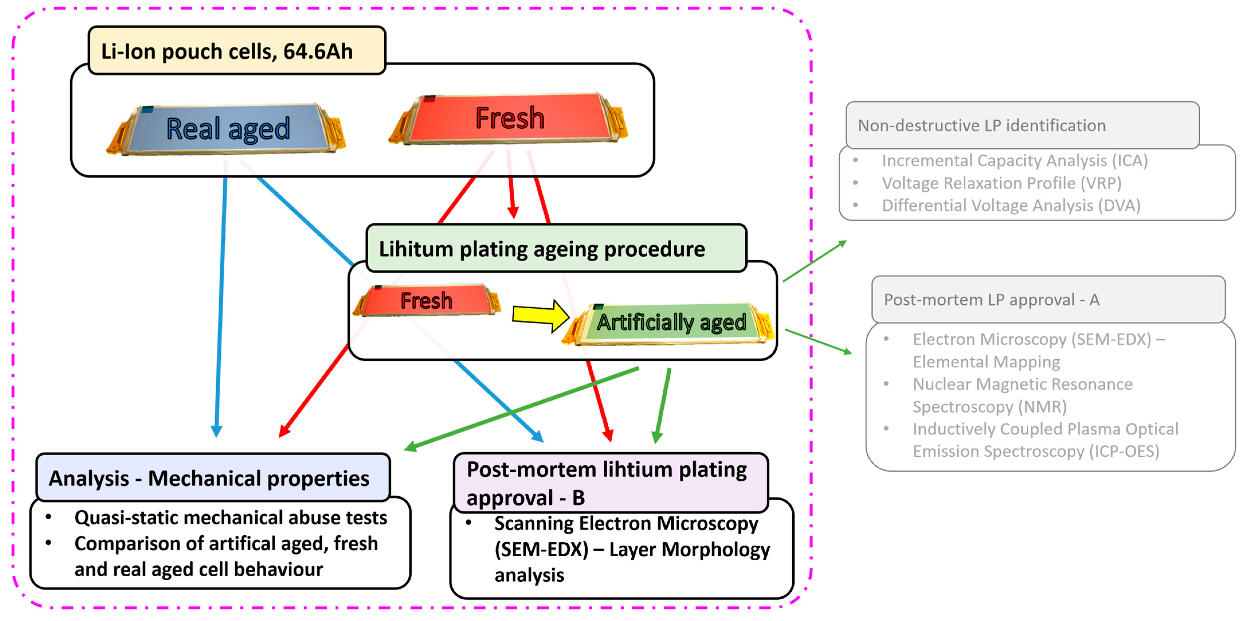
Figure 1. Schematic diagram showing research approach to investigating the effect of LP on LIBs properties. The focus of this study is highlighted.
Batteries 11 00330 g001
Figure 2. Illustration of quasi-static test setup layout. (a) Test detailed layout side view; (b) test detailed layout top view; (c) picture of test setup.
Batteries 11 00330 g002
Figure 3. Quasi-static compression tests results of fresh, RA, and AA cells. The maximum failure forces are indicated (dotted lines), along with the limits used for stiffness calculation (black boxes): (a) 0% SOC; (b) 100% SOC.
Batteries 11 00330 g003
Figure 4. Voltage over displacement data showing ISC behavior, dashed lines showing point of failure: (a) 0% SOC shows deeper ISC for F and RA cells; (b) 100% SOC shows extreme ISC for AA cell; (c) enlarged 0% SOC until 2.5 mm shows slight increase in voltage of AA cells before contact between cell and impactor.
Batteries 11 00330 g004
Figure 5. Visual inspection and SEM morphology analysis of aged cells: (a) Anode layer of AA_LP cells showing randomly distributed light gray patterns. The red dotted circle highlights edge of used impactor (here 50 mm diameter) and circular gray ring around that area; the blue rectangle highlights disintegration of anode layer at cell boundaries during disassembly; the green rectangle shows area of SEM analysis. (b) SEM-image of gray area identified in visual inspection; additional non-uniform mossy-type metallic lithium layer on graphite particles (enclosed in yellow lines). (c) Anode layer of RA cell showing SEI on graphite particles as well as Cu residuals. Lower magnification SEM images are shown in Appendix A.
Batteries 11 00330 g005
Table 1. Cell nomenclature and aging history.
Cell Nomenclature
Cell StatusSOHcHistory
Fresh (F)100%Fresh cell, not used in application
Artificially aged (AA)80–82%20 cycles under LP conditions
Real aged (RA)93%Used in a car for ca. 160,000 km
Table 2. Cell thickness measurements at different SOCs, along with breathing and swelling values.
Cell Thickness (mm)Breathing
(0–100% SOC) (mm)
Swelling vs. F
(0% SOC) (mm)
Cell Type0% SOC100% SOC
F11.25 ± 0.1011.75 ± 0.06+0.5 (+4.4%)-
AA12.27 ± 0.0712.73 ± 0.10+0.46 (+3.7%)+1.02 (+9.1%)
RA11.78 ± 0.0812.05 ± 0.090.27 (+2.3%)+0.53 (+4.7%)
Table 3. Cell peak failure force and corresponding failure displacement are presented.
Cell TypePeak Failure Force (kN)Failure Deformation (mm)Difference to F
0% SOC100% SOC0% SOC100% SOCPeak Failure Force (kN)Failure Deformation (mm)
0% SOC100% SOC0% SOC100% SOC
F45 ± 0.557 ± 22.10 ± 0.032.24 ± 0.05----
AA32 ± 0.536 ± 0.52.24 ± 0.072.24 ± 0.1−13 (−28%)−21 (−37%)+0.14 (+6%)0 (0%)
RA33 ± 0.642 ± 0.81.79 ± 0.052.04 ± 0.6−12 (−26%)−15 (−26%)−0.31 (−15%)−0.20 (−11%)
Table 4. Cell stiffness at SOC 0% and 100%. Stiffness values are also compared to fresh cells.
Cell Stiffness (kN/mm)
Cell Type0% SOC100% SOC∆ Relative to Fresh
0% SOC100% SOC
F29.45 ± 0.329.04 ± 0.19--
AA24.76 ± 1.025.16 ± 0.45−4.7 (16%)−3.9 (−13.5%)
RA27.27 ± 0.2128.62 ± 0.20−2.2 (−7.4%)−0.4 (1.4%)
Disclaimer/Publisher’s Note: The statements, opinions and data contained in all publications are solely those of the individual author(s) and contributor(s) and not of MDPI and/or the editor(s). MDPI and/or the editor(s) disclaim responsibility for any injury to people or property resulting from any ideas, methods, instructions or products referred to in the content.