Article

Failure Analysis of Fire in Lithium-Ion Battery-Powered Heating Insoles: Case Study

Berkeley Engineering and Research, 808 Gilman St., Berkeley, CA 94710, USA
*
Author to whom correspondence should be addressed.
Batteries 2025, 11(7), 271; https://doi.org/10.3390/batteries11070271
Submission received: 27 May 2025 / Revised: 1 July 2025 / Accepted: 14 July 2025 / Published: 17 July 2025
(This article belongs to the Section Battery Performance, Ageing, Reliability and Safety)

Abstract

This study investigates a lithium-ion battery failure in heating insoles that ignited during normal walking while powered off. Through comprehensive material characterization, electrical testing, thermal analysis, and mechanical gait simulation, we systematically excluded electrical or thermal abuse as failure causes. X-ray/CT imaging localized the ignition source to the lateral heel edge of the pouch cell, correlating precisely with peak mechanical stress identified through gait analysis. Remarkably, the cyclic load was less than 10% of the single crush load threshold specified in safety standards. Key findings reveal multiple contributing factors as follows: the uncoated polyethylene separator’s inability to prevent stress-induced internal short circuits, the circuit design’s lack of battery health monitoring functionality that permitted undetected degradation, and the hazardous placement inside clothing that exacerbated burn injuries. These findings necessitate a multi-level safety framework for lithium-ion battery products, encompassing enhanced cell design to prevent internal short circuit, improved circuit protection with health monitoring capabilities, optimized product integration to mitigate mechanical and environmental impact, and effective post-failure containment measures. This case study exposes a critical need for product-specific safety standards that address the unique demands of wearable lithium-ion batteries, where existing certification requirements fail to prevent real-use failure scenarios.

Graphical Abstract

1. Introduction

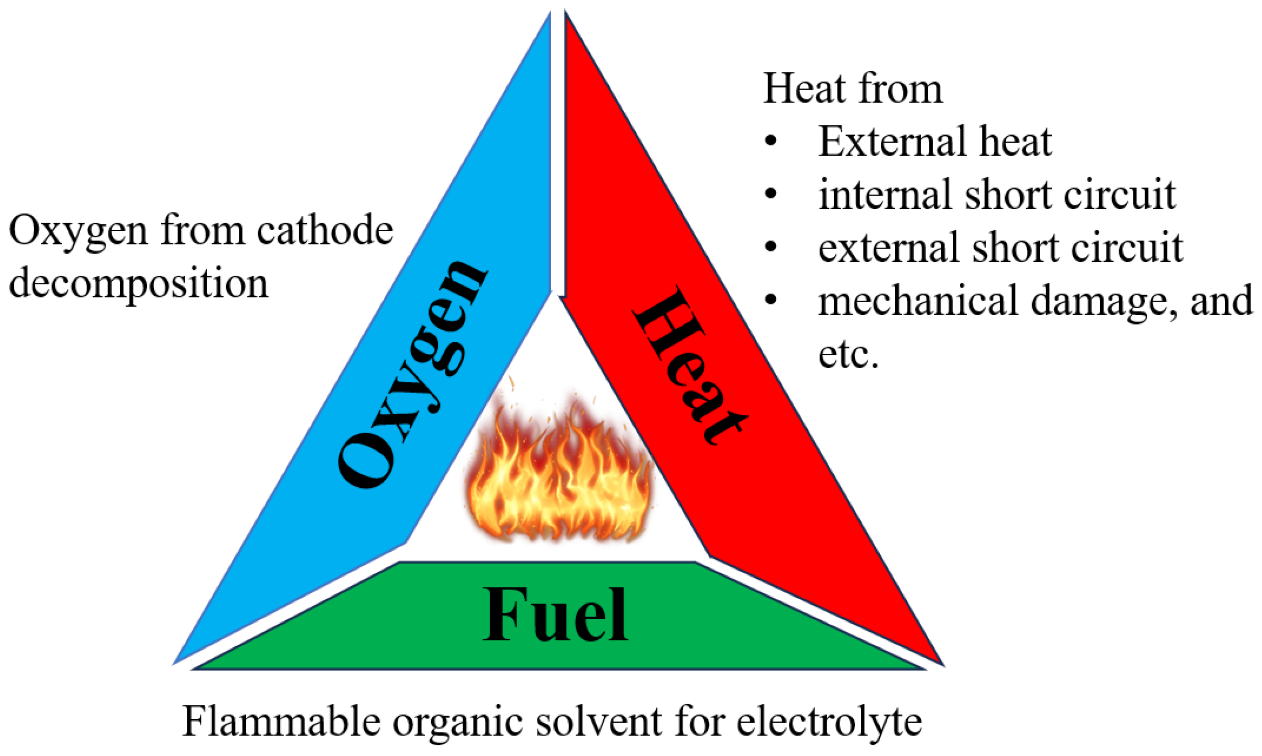
1.1. Safety Concerns

Lithium-ion batteries (LIBs), first mass-produced by Sony in 1991 [1], are widely used for their lightweight design, compact size, and long life. Their applications fall into the following three categories [2]:
1.
Energy applications with high capacity and low current: cell phones, laptops, cameras, and power banks.
2.
Power drive applications with moderate current: electric vehicles, e-bikes, scooters, etc.
3.
Power tool applications with high current output: power tools.
Despite their advantages, LIBs present significant safety concerns due to their flammable organic electrolytes [3]. Unlike conventional rechargeable batteries that primarily generate heat during failure events, LIBs pose a compounded hazard by: (1) generating more heat due to their higher energy density, (2) containing their own fuel source (flammable electrolytes) and (3) releasing oxygen through cathode decomposition at elevated temperatures [4]. LIBs complete the fire triangle (Figure 1) when hard internal short circuits (ISCs) occur [5]. These “hard” ISCs involve direct contact between aluminum foil and copper foil or between aluminum foil and anode [5,6]. Such short circuits can be caused by mechanical damage, thermal abuse, electrical failures, or manufacturing defects. The interplay of these factors makes LIB systems inherently riskier than other battery technologies, necessitating stricter safety measures.
It is important to note that in battery terminology, “cell” and “battery” represent distinct concepts. A cell refers to the basic electrochemical unit, while a battery denotes a ready-to-use, safety-integrated assembly [7,8]. For example, AA alkaline and nickel metalhydride (NiMH) single cells are classified as “batteries” due to their inherently low risk. In contrast, LIBs require additional protection circuits, such as a battery management system (BMS) or protection circuit board (PCB), to monitor voltage, current, temperature, and state of health (SOH). Crucially, LIBs and, in particular, the electrode assembly (referred to as the “jelly roll”) must not be used as load-bearing components in product designs.

1.2. Wearables with LIBs

The integration of lithium-ion batteries into wearable textiles, such as heated clothing, gloves, socks, and insoles, presents both technological opportunities and safety challenges. Between 2011 and 2024, the U.S. Consumer Product Safety Commission (CPSC) issued four separate recalls for LIB-powered jackets, gloves, and socks (Table 1). In one instance, the CPSC cited four reports of fires caused by heated socks [9]. Another study documented a case of a 43-year-old man who sustained a full-thickness burn on his leg after wearing heated socks for four hours while skiing. Although the battery did not catch fire or melt the fabric, the injury should have been the result of prolonged exposure to low-temperature heat [10], highlighting inadequate thermal management in the product design or the battery pack.
Although the CPSC has not issued recalls for heating insoles, an Internet search and our company’s records indicate 12 cases of fires and subsequent burn injuries involving such products since 2023 (Table 2). Among these cases, 11 victims were male and one case did not disclose gender. In particular, in seven cases, the heating insoles were reported to have been powered off at the time of the incident, while the remaining five cases did not specify whether the devices were on or off. Injuries predominantly affected the right foot (7 of 12 cases), followed by the left foot (3 of 12 cases), with two cases not specified.
This study presents a comprehensive analysis of a LIB-powered heating insole failure that occurred while the device was powered off. Our multidisciplinary investigation incorporates radiography, advanced material characterization, electrical diagnostics, thermal profiling, biomechanical gait simulation, and charge-discharge cycling to establish the failure mechanism. Based on our findings, we identify critical design flaws and propose safety guidelines for future LIB-powered wearable products.

2. Materials and Methods

2.1. Background

Mr. John Doe purchased a pair of heating insoles for his work boots. The insoles offered three power settings: low (40–45 °C), medium (50–55 °C) and high (55–65 °C). Mr. John Doe used the medium setting intermittently on cold days. His routine involved 4 h of walking and 4 h of sitting per workday. On the 13th workday, the right insole caught fire while he was stepping down, despite the heating function being off. The insoles had been charged prior to the incident and had never been wet, washed, or damaged.

2.2. Materials

We examined the subject failed insoles and two additional exemplars (the same brand purchased on eBay). Based on X-ray imaging (XRS4MD, Golden Engineering, Centerville, IN, USA) the battery was placed under the heel, with heating wires in the sole area (Figure 2). The subject matched Exemplar #1, featuring a narrow metal backing plate underneath the battery. Exemplar #2 (updated version) omitted the metal plate and used a battery of a different form factor and with a different PCB design.

2.3. Testing

The investigation used both exemplar insoles (new condition) and subject insoles (used condition), with testing protocols detailed in Table S1. The initial characterization involved X-ray computed tomography (CT) (Nikon XT H 225 ST, Nikon USA, Melville, NY, USA) of the failed insoles followed by complete disassembly of all units (Figure 3).
For material analysis, exemplar left foot cells were unrolled to examine electrode morphology via scanning electron microscopy (SEM) (Hitachi S3600N, Hitachi, Santa Clara, CA, USA) and elemental composition via energy dispersive spectroscopy (EDS) (Xplore 30, Oxford Instruments NanoAnalysis, Concord, MA, USA). Particular attention was paid to the metal backing plate of Exemplar #1. Polymer components (insole material, battery case and battery separator) were characterized by Fourier transform infrared spectroscopy (FTIR) (Nicolet iS10, Thermo Fisher Scientific, Fremont, CA, USA).
For circuit analysis, PCB architectures were compared using digital microscopy (Keyence VHT-X1, Keyence, San Jose, CA, USA). The resistance of the heating wire was quantified (Extech 380560 Milliohm Meter, Extech Instruments, Nashua, NH, USA), followed by charge-discharge profiling using original chargers. Discharge cycles in high, medium and low power settings employed a 10 m Ω shunt resistor for current measurement, with data acquisition (GL240 Data logger, Graphtec America, Irvine, CA, USA) at 100 Hz. The maximum charging voltage and discharge cutoff voltage were measured under open-circuit voltage (OCV) conditions.
The exemplar right insoles were first subjected to thermal performance evaluation, followed by gait analysis and charge-discharge cycling. Thermal performance was evaluated under two conditions: (1) Exemplar #1 operated at medium power within an insulated winter coat for 21 min, and (2) both exemplars operated at high power under ambient conditions (19 °C) until battery depletion. K-type thermocouples were positioned at both the insole surface and the battery cell surface. Temperature data was recorded (Extech SDL200, Extech Instruments, Nashua, NH, USA) at 0.5 Hz.
After thermal testing depleted the batteries, mechanical loading was simulated using a pressure-sensitive film (Fujifilm Ultra Extreme Low 5LW, FUJIFILM America, Valhalla, NY, USA) for gait analysis. The film was cut to the dimensions of batteries and placed under the cell. A coworker carrying weights (to match Mr. John Doe’s body weight of 122.5 kg) walked 12 steps for each exemplar insole. The resulting stress distributions on the film were then documented.
Following gait analysis, the exemplar right insoles underwent 10 charge-discharge cycles. The internal impedance was measured at 1 kHz (Hopetech CHT3554, Hopetech Instruments, Changzhou, China) for the exemplar units.

3. Results

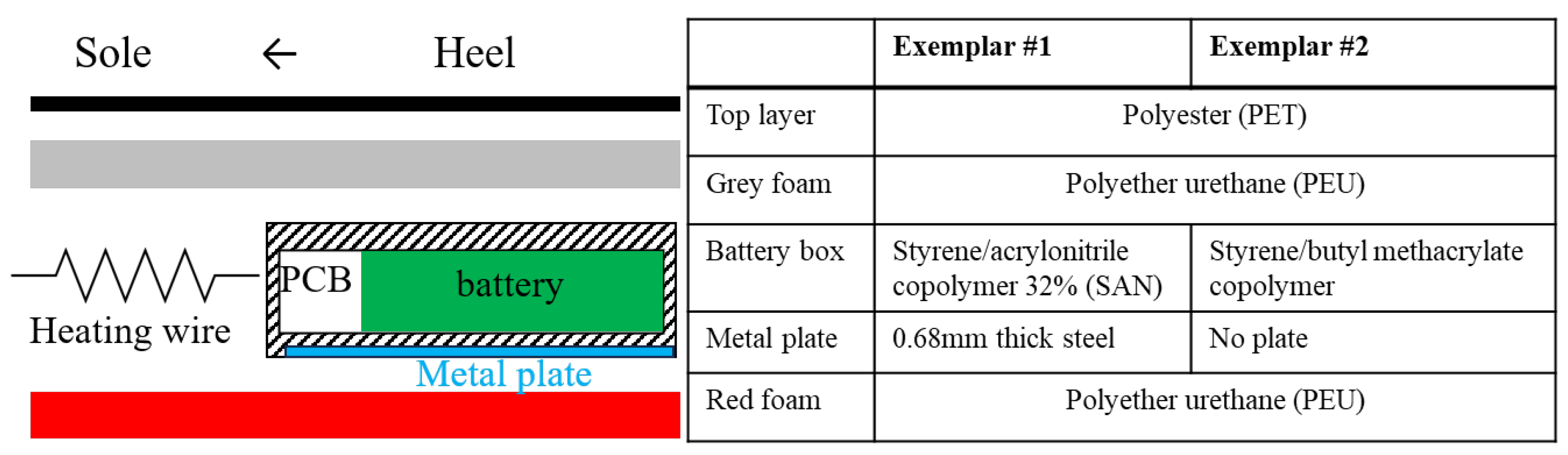
3.1. Insole Material

The insole consists of three layers: a top layer, a middle grey foam and a bottom red foam. The battery box and heating wire were sandwiched between the grey and red foam. Figure 4 illustrates the structure of the insole. The top layer is made of polyester (PET) fabric. The grey and red foams are made of polyether urethane (PEU). The battery case materials differ, but are both styrene-based polymers. Both the subject insole and Exemplar #1 include a 0.68 mm thick steel plate beneath the plastic case. FTIR, SEM, and EDS results for insole materials are provided in Figures S1 and S2.

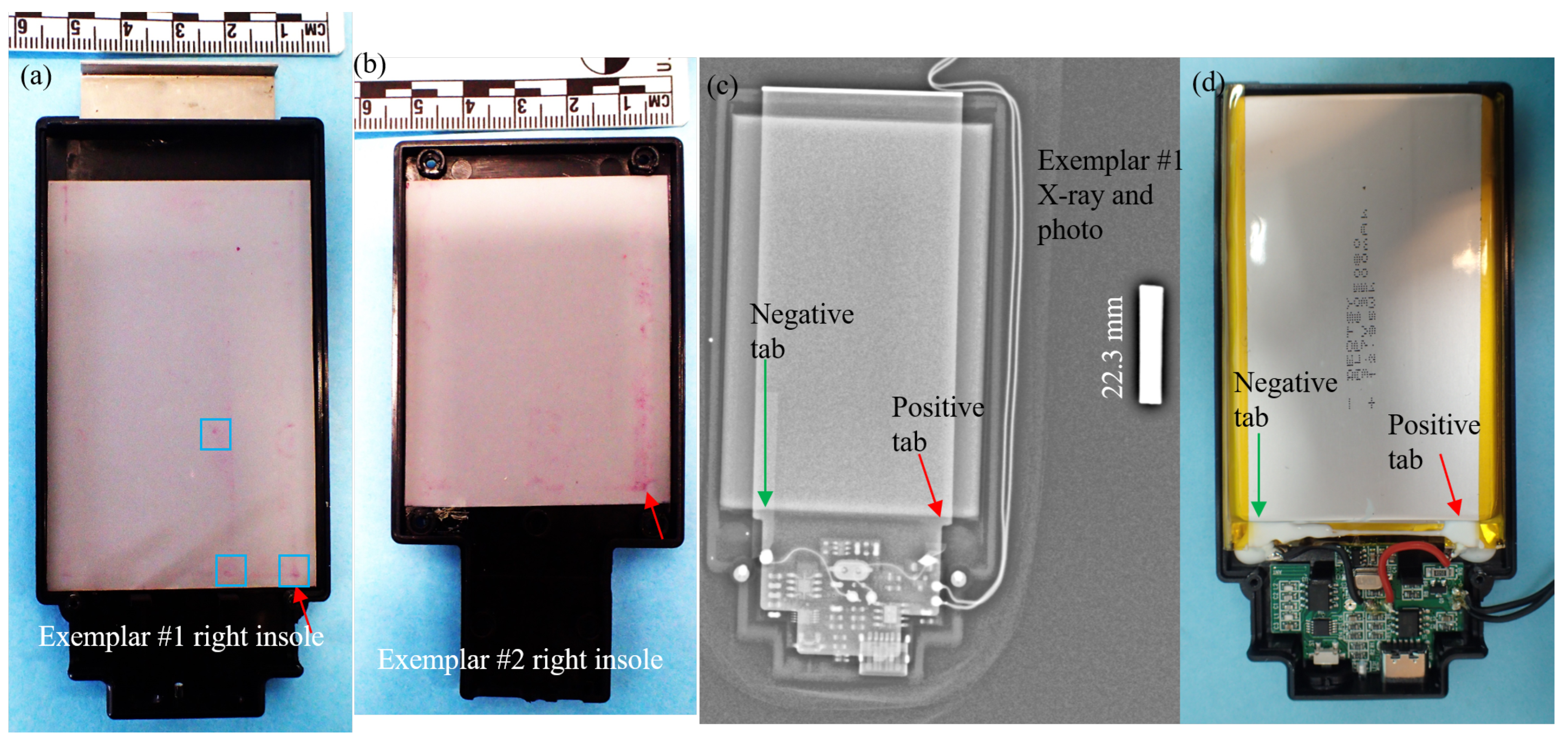
3.2. Battery Cell Composition

The battery cell composition was characterized through SEM, EDS, and FTIR analyses (Figures S1 and S3), with key comparative data summarized in Table 3. Both prismatic cells followed a six-digit form factor notation. The form factor of the Exemplar #1 cell is 605080 (6.0 mm thick × 50 mm wide × 80 mm long), with a capacity of 3500 milliamp-hour (mAh) and a nominal voltage of 3.7 V. The form factor of Exemplar #2 is 535265 ( 5.3   ×   52   ×   65 mm), with a capacity of 3000 mAh and a nominal voltage of 3.8 V.
The battery cell of Exemplar #1 used lithium nickel-cobalt-manganese oxide (NCM) in the cathode, with Ni:Co:Mn = 40:15:45 (NCM 40/15/45). The battery cell of Exemplar #2 used lithium cobalt oxide (LCO) in the cathode, typical for energy applications. Although both cells incorporated graphite anodes and polyethylene (PE) separators, neither implemented ceramic-coated separators, a critical design omission that raises internal short-circuit risks [6]. Both cathode chemistries are capable of maintaining operational stability up to at least 60 °C [2,3,22]. The internal resistances were measured to be 26 milli Ohm (m Ω ) for Exemplar #1 and 45 m Ω for Exemplar #2.

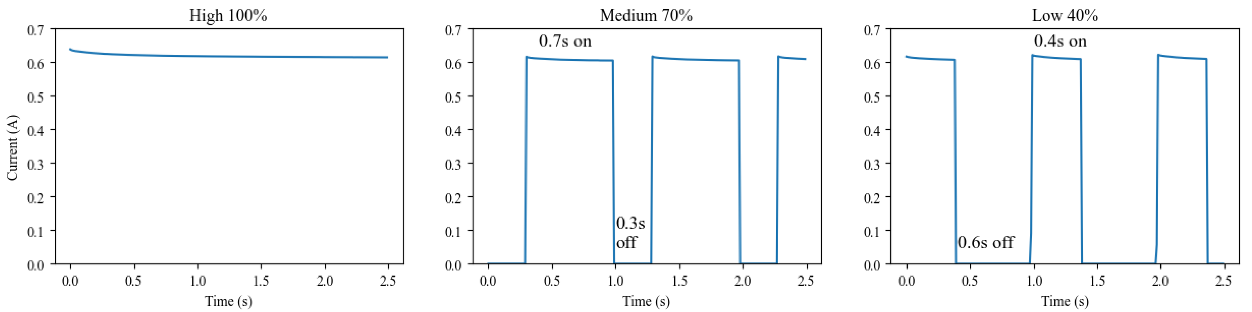
3.3. Electrical Performance

The PCBs in both exemplars exhibit visual differences (Figure S4) while maintaining identical function modules: (1) microcontroller, (2) wireless module, (3) charging module, and (4) single-cell battery protection module. The integrated circuits (ICs) in the charging and protection modules vary depending on the cathode chemistry and nominal voltage. For both exemplars, the charging module ICs restrict the charging current to less than 1 A [23,24]. During charging, Exemplar #1 (NCM 40/15/45 cathode) reached a maximum charging voltage of 4.22 V, while Exemplar #2 (LCO cathode) reached 4.30 V (Table 4). Our measurements confirm that neither PCB allowed overcharging above specified maximum charging voltages or currents.
Notably, both PCB designs lack temperature sensors for monitoring battery cells or heating wires. This is a significant omission, given the thermal management requirements of LIBs in wearable applications. In addition, neither PCB incorporates battery health diagnostic functions [27,28,29] to detect defects or aging in the battery.
Both exemplars employ heating wires with 6 Ω resistance and the maximum heating currents are below 0.7 A, consistent with energy-optimized applications requiring prolonged service. Power modulation is achieved through pulse width modulation (PWM), maintaining constant current amplitude but varying duty cycles: 100% (high), 70% (medium), and 40% (low) settings (Figure 5). The protection circuitry prevents over-discharge, with both systems terminating operation around 3.3 V.

3.4. Insole Heating Test

Heating test results are presented in Table 5. The medium power test of Exemplar #1’s right insole was terminated after 21 min (or 0.35 h) under insulated conditions. The sole area reached 74.2 °C while the battery cell remained cool (20.5 °C). This thermal isolation results from the low thermal conductivity (<0.3 W/m·K) of the insole and battery case materials [30]. In particular, the steel plate (thermal conductivity 15 W/m·K [31]) did not contribute significantly to heat conduction. Under high-power non-insulated conditions, both exemplar insoles reached maximum temperatures of over 55 °C in 20 min (detailed data in Figure S5). Battery temperatures rose from 19 °C ambient to 26.6 °C and 30.1 °C, respectively. These results establish upper (insulated) and lower (non-insulated) thermal bounds for real-world use, confirming that battery temperatures would not exceed 40 °C in normal operation despite the absence of PCB temperature sensors.
The observed temperature difference between exemplar battery cells (26.6 °C vs. 30.1 °C) correlates with their internal resistances (26 m Ω vs. 45 m Ω ), demonstrating the expected relationship where higher resistance generates greater Joule heating at equivalent currents.

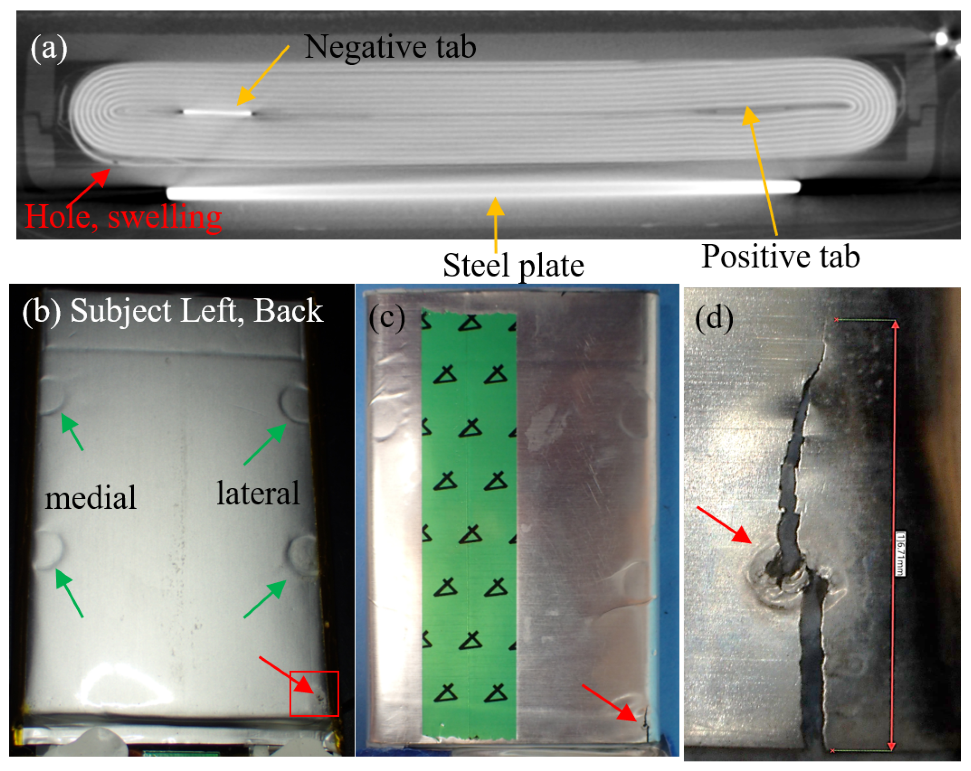
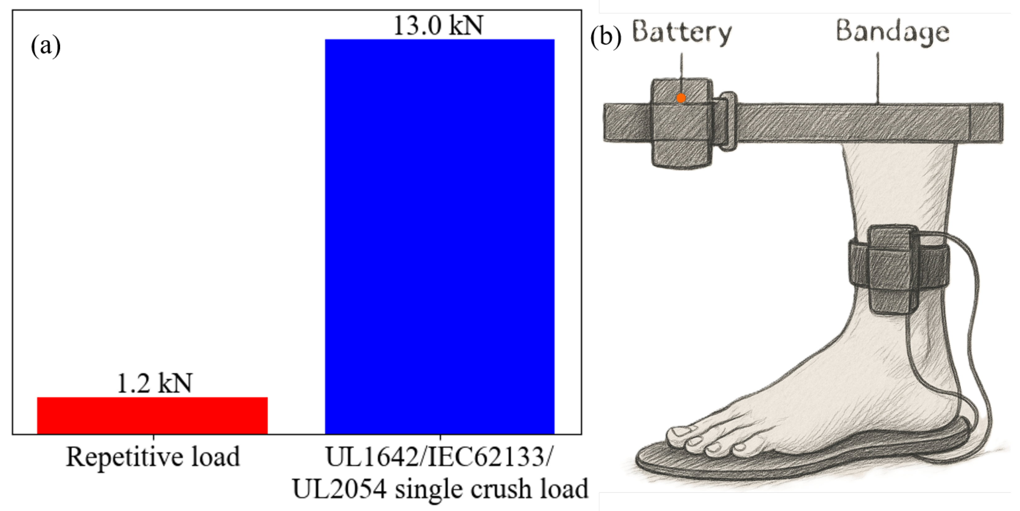
3.5. Battery Pressure Test

Gait analysis reveals four key phases in normal walking (Figure 6), with the heel enduring maximum mechanical loads during both impact (initial contact) and weight bearing (stance phase) [32]. The pressure mapping (Figure 7) identified maximum stress concentrations along the battery’s lateral edge at the heel end. For Exemplar #1, this high stress zone coincided precisely with (1) the location of the positive tab and (2) the edge of the steel backing plate, creating a critical failure point for mechanical stress concentration. Furthermore, the insole of exemplar #2 experienced more stress than exemplar #1 due to a smaller battery size, resulting in less area over which to spread the applied load.

3.6. Charge-Discharge Cycle Test

The insole batteries of both Exemplar #1 and Exemplar #2 underwent 10 charge-discharge cycles at medium power under no-load conditions, more than the number of cycles Mr. John Doe had used prior to failure. After cycling, neither cell exhibited swelling. The internal resistance remained almost unchanged (Table 6), indicating that activation of the heating function alone could not have caused the observed cell swelling and failure. In contrast, the battery of the subject left insole showed swelling and an elevated internal impedance of 36 m Ω after fewer than 10 charge-discharge cycles under walking conditions. These findings suggest that cyclic mechanical stress during walking, rather than electrical cycling alone, contributed to swelling and increased internal impedance.

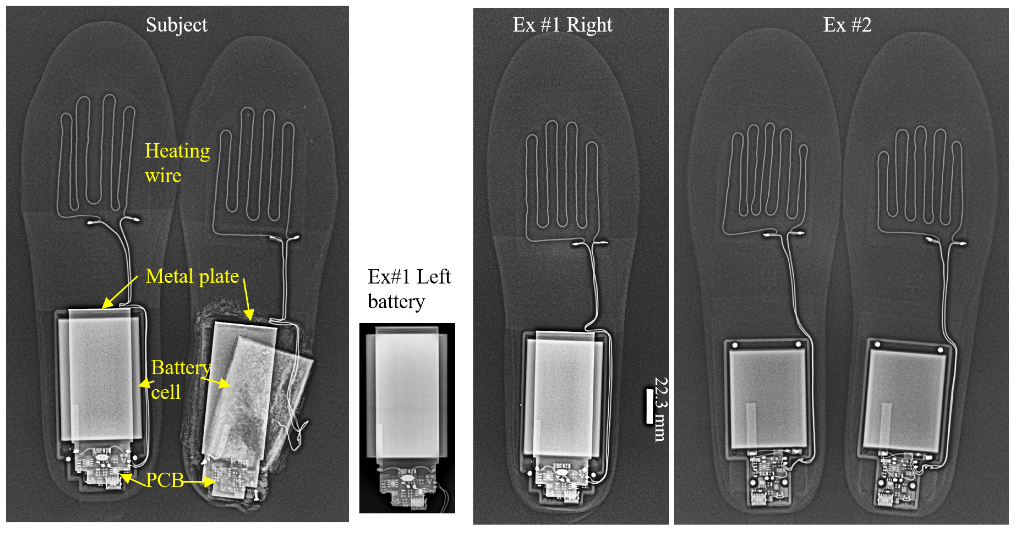
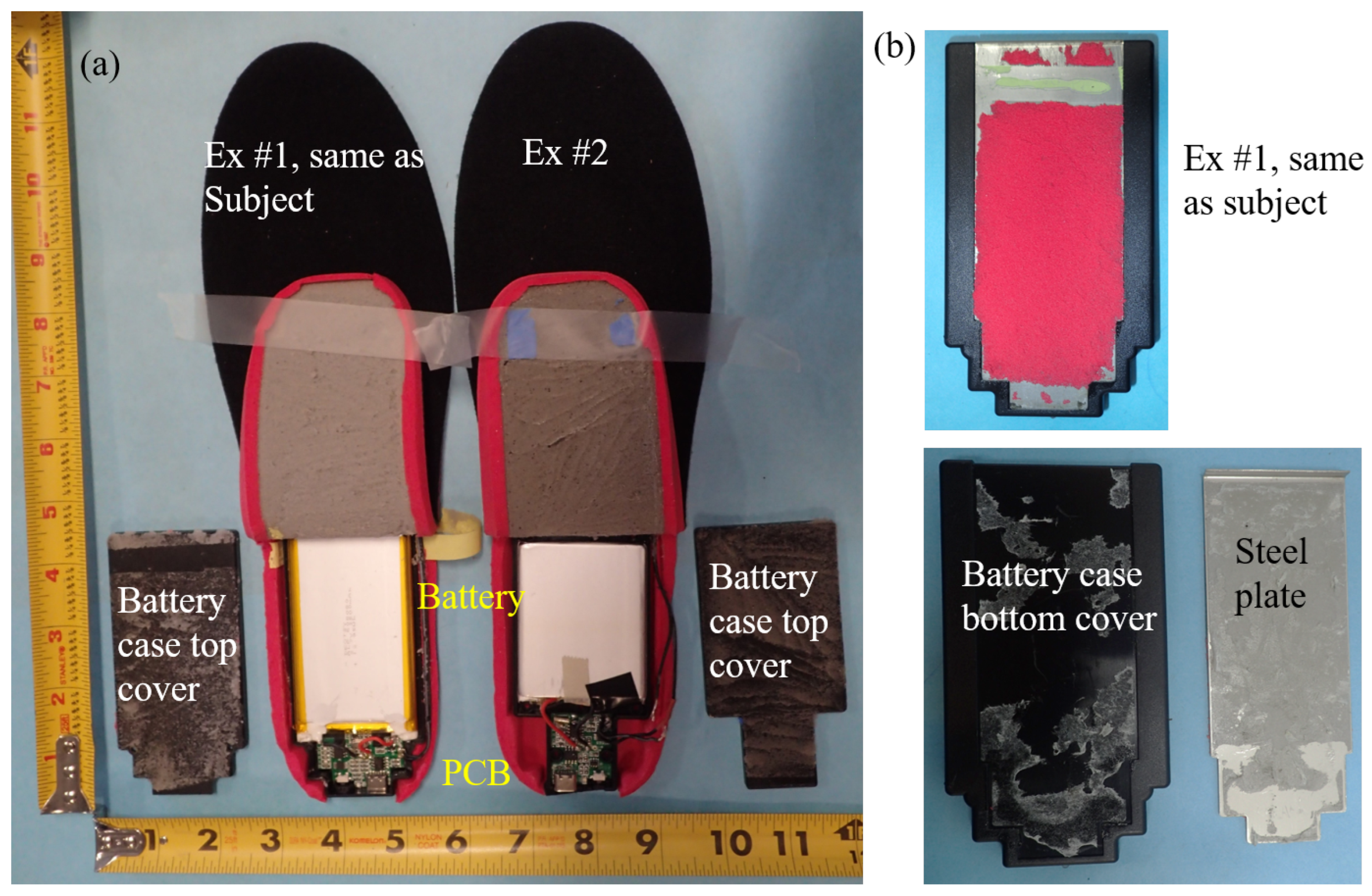
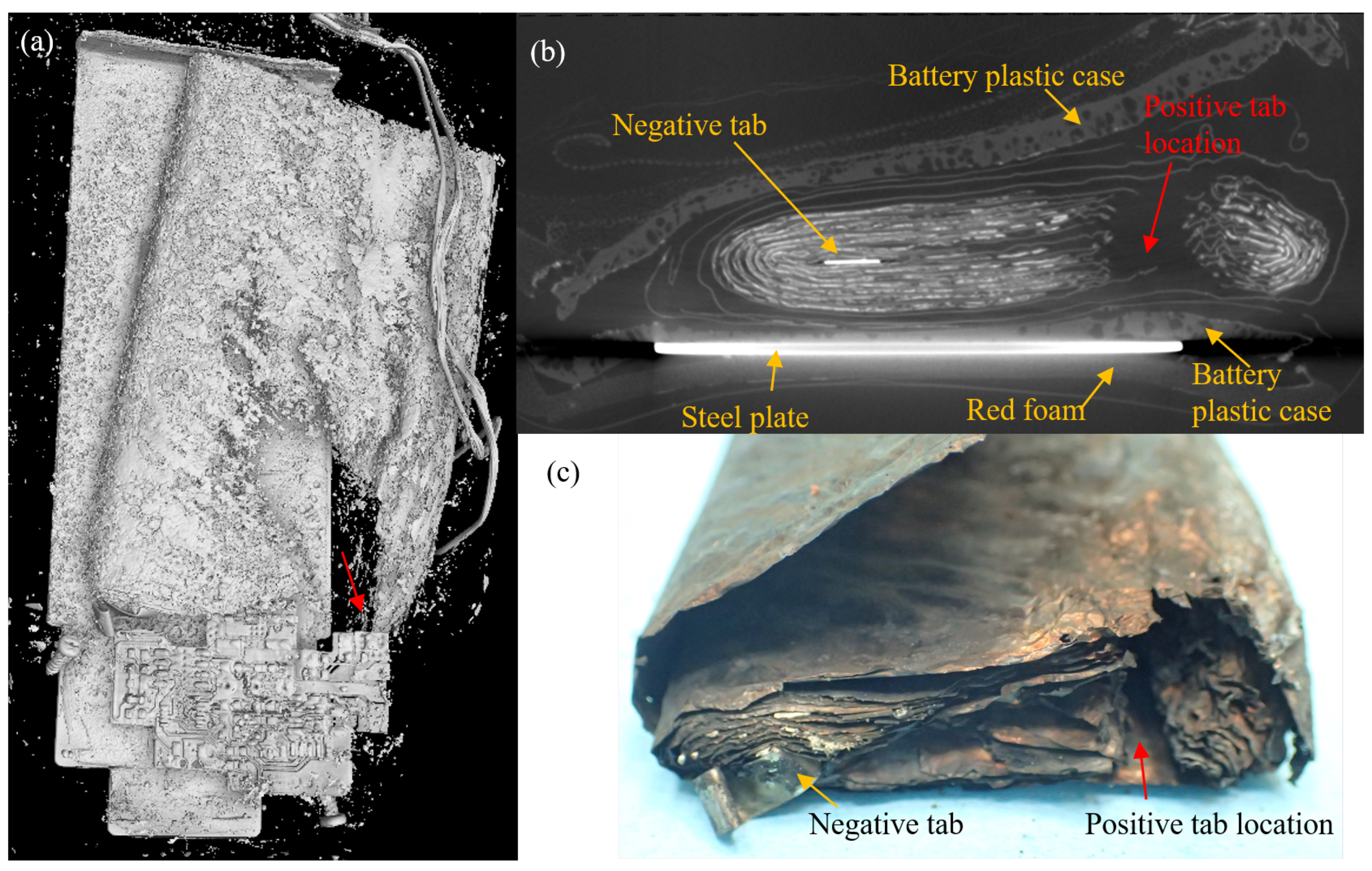
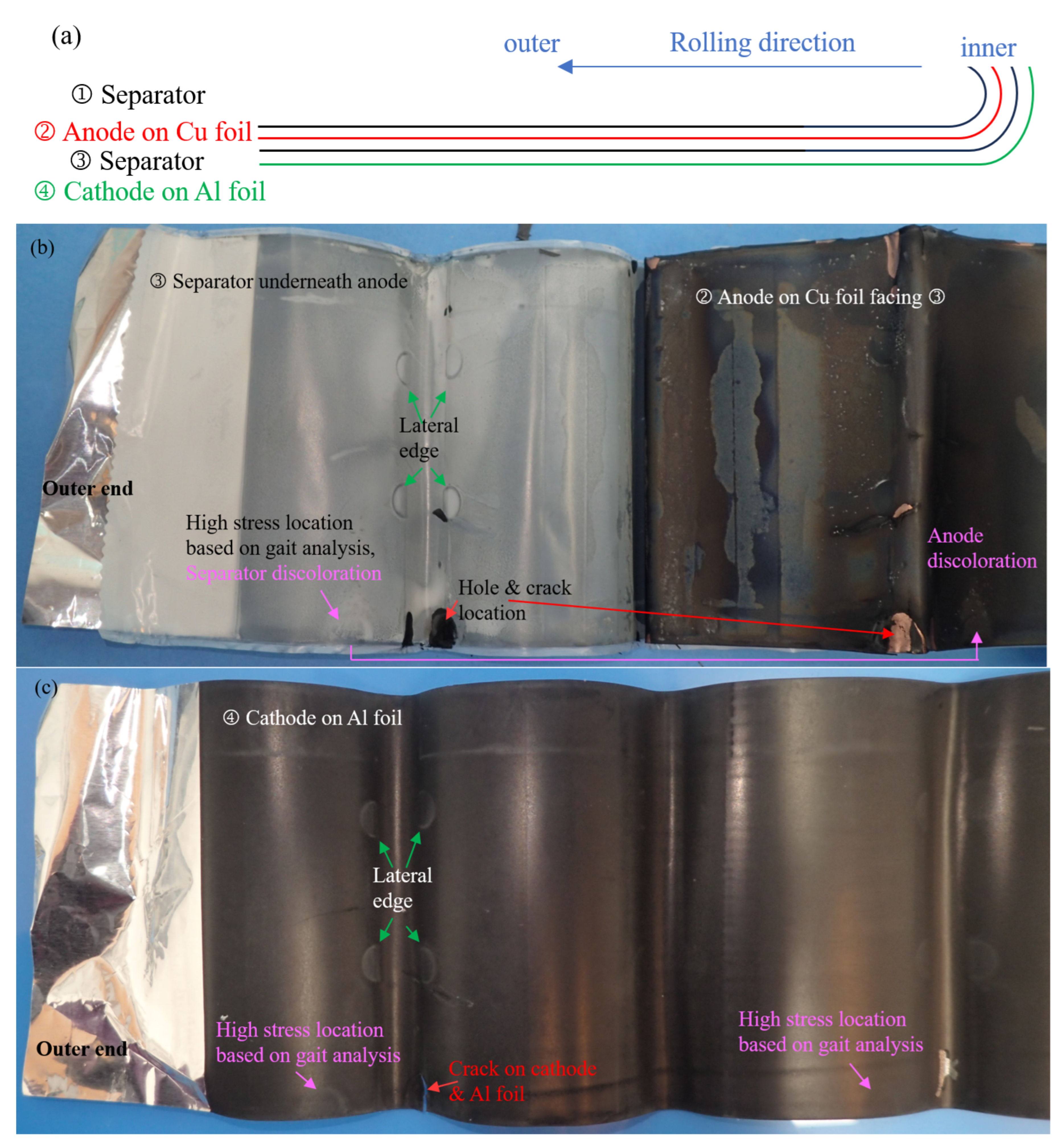
3.7. Subject Insole CT and Disassembly

CT imaging of the failed right insole (Figure 8a) confirms that ignition originated at the battery’s heel-side lateral edge (Figure 8b), precisely where the positive tab and the steel plate edge are located (Figure 8c). This location matches the region of maximum mechanical stress identified through gait analysis using exemplar insoles.
The battery of the subject’s left insole retained a residual voltage of 4.06 V fourteen months after the incident, indicating that the failure occurred during a fully charged state. CT reconstruction of this unit (Figure 9a) shows an intact but swollen jelly roll, with visible physical expansion compared to the new exemplar batteries. Mechanical deformation was more pronounced on the lateral side than on the medial side (Figure 9b), with a distinct perforation and cracks at the lateral-heel corner of the battery’s aluminum casing (Figure 9b) and jelly roll (Figure 9c,d). The perforation is consistent with the CT observations (red arrows in Figure 9).
The jelly roll consists of a vertically stacked assembly: separator, copper foil with double-sided anode coating, separator, and aluminum foil with double-sided cathode coating. The positive and negative tabs are placed at the inner end, with the stack folded toward the outer end.
Unrolling the subject’s left battery jelly roll revealed discoloration of the separator, anode, and cathode (Figure 10) at the high stress location identified during gait analysis (Figure 7), suggesting potential internal short-circuit development. In particular, this discoloration was not detectable by CT imaging. The perforation visible by the CT scan (Figure 9a) corresponds to a crack in the cathode-coated aluminum foil.

4. Root Cause Analysis and Design Concerns

4.1. Root Cause Analysis

The fire incident occurred while the device was powered off, confirming an internal short circuit as the failure mechanism. Our comprehensive analysis systematically eliminated potential causes through multiple investigative approaches. PCB examination ruled out electrical abuse scenarios, including overcharge and over-discharge. Heating tests excluded the possibility of battery cell thermal abuse. Charge-discharge cycling demonstrated that electrical cycling alone, without mechanical loading, does not induce battery swelling or impedance elevation. Gait analysis revealed that the high-stress location precisely matched the failure origin in the right insole battery, while separator discoloration was observed in the subject’s swollen left insole battery. These findings provide conclusive evidence that cyclic mechanical stress induced the internal short circuit. The failure resulted from four synergistic factors: application-induced cyclic stress, inadequate separator design, absence of battery health monitoring, and lack of post failure containment plan as illustrated in Figure 11.
Cell-Level Design Flaws. The battery cell incorporated an uncoated polyethylene separator that lacked ceramic reinforcement. A ceramic coating could have provided multiple benefits including improved puncture resistance, prevention of thermal shrinkage under compression, and maintained structural integrity above 100 °C. Such ceramic-coated separators might have prevented an ISC, as supported by previous research [6].
Circuit-Level Deficiency. The PCB design lacked battery health monitoring (SOH diagnostics) to detect damage [27,28,29] and the corresponding charge-disabling capability upon defect detection. This oversight is particularly crucial given that the risk of fire increases significantly at full charge, a fact recognized by transportation regulations that limit lithium batteries to 30% charge for air transport [33].
In this case, the left insole showed clear signs of accelerated degradation, including visible swelling and elevated internal resistance, consistent with the breakdown of solid electrolyte interphase (SEI) and gas evolution [3,4,5,28]. While pouch cells typically swell after hundreds of charge-discharge cycles without load [34], the left battery swelled after fewer than 10 cycles under repeated compressive load. Implementation of SOH monitoring could have potentially identified this degradation and prevented the incident by disabling the charging process and keeping the battery at low charge.
Product-Level Design Issues. The battery’s placement beneath the heel subjected it to repetitive mechanical stress during normal gait. The right insole experienced catastrophic failure first due to greater loading from right-foot dominance, while the left insole sustained damage without ignition.
Current battery safety standards (UL 1642 [35], IEC 62133 [36] and UL 2054 [37]) require fully charged batteries to survive a single 13 kN crush test without catching fire. However, the heel load (∼1.2 kN, or 122.5 kg body weight) was less than 10% of the test load (Figure 12a). The real failure occurred due to repeated low-level stress from walking, a scenario not addressed by current safety standards. This highlights the need for specific safety rules for specific products or applications.
Post-Failure Containment Issues. In multiple incident reports involving LIB-powered heating insoles (Table 2), users described difficulty removing burning insoles from footwear during thermal runaway events. Relocating the battery outside clothing layers could mitigate injury severity during such failures (Figure 12b).
In summary, the insole failures resulted from four interdependent factors: (1) cumulative mechanical damage from gait-induced cyclic stress, (2) no safety-reinforced separator, (3) absence of critical battery health monitoring, and (4) hazardous placement within clothing.
Although implementing safety-reinforced separators, state-of-health (SOH) monitoring, and thermal sensors would increase manufacturing costs, and relocating batteries outside footwear may reduce user convenience, these measures are critical to mitigating severe safety risks. Documented cases of thermal runaway and burn injuries, including failures with devices powered off, demonstrate that current cost-optimized designs have unacceptable safety trade-offs. Proactive investment in robust safety systems is not just a technical improvement, but an ethical obligation for wearable battery applications, where failure consequences directly impact user well-being.

4.2. Battery Design Concerns

To ensure safe lithium-ion battery design, four key levels must be addressed: cell, circuit, product integration, and post-failure containment (Figure 13).
At the cell level, the separator and SEI formation must be optimized for the specific application. Additional considerations include preventing localized hot spots and manufacturing defects that could trigger thermal runaway. Current safety standards include UL 1642 [35], IEC 62133 [37], and UN 38.3 [38] (for transportation), along with country-specific requirements.
At the battery circuit level, all battery circuits should (1) prevent electrical abuse (overcharge/over-discharge), (2) maintain temperatures within the cell manufacturer’s specified range to avoid SEI decomposition; (3) monitor battery health to disable unsafe cells before thermal runaway occurs. These designs must meet the same core standards as cell-level requirements (UL 1642, IEC 62133, UN 38.3).
At the product level, product-specific battery designs must (1) accommodate geometric constraints, (2) protect against mechanical stresses (crush, impact, vibration, cyclic loading), and (3) provide environmental protection (against moisture, chemicals, foreign materials). The inherently soft jelly roll structure of lithium-ion cells makes them particularly vulnerable to mechanical stresses. When mechanical stress is unavoidable, protective load shielding cases should be implemented. Certain applications may require compliance with specialized safety standards beyond basic requirements, such as UL 2271 [39] for light electric vehicles and UL 2580 [40] for electric vehicles.
Equally critical are post-failure containment measures, which should incorporate: fire-retardant materials to suppress combustion, adequate cell spacing with thermal insulation in multi-cell configurations to prevent thermal runaway propagation, and in wearable applications, strategic positioning outside clothing to minimize burn injury risks. These measures collectively improve overall system safety when primary protection mechanisms fail.

4.3. Additional Consideration

4.3.1. Exemplar #2 Battery Safety Assessment

While no fire incidents have been reported for Exemplar #2 insoles, our gait analysis reveals these units may present greater fire risk than Exemplar #1 due to their smaller form factor and correspondingly higher observed stress (Figure 7). Although Exemplar #2 employs a different cathode chemistry (LCO versus NCM in Exemplar #1), this difference did not contribute to thermal runaway in this case. While cathode chemistry typically influences operational voltage range and safety through oxygen release temperature thresholds, the present failure resulted from mechanical stress rather than electrochemical factors. The low operational current (<1 A) and absence of thermal abuse indicate that stress (load per unit area) served as the primary failure mechanism.

4.3.2. Study Limitations
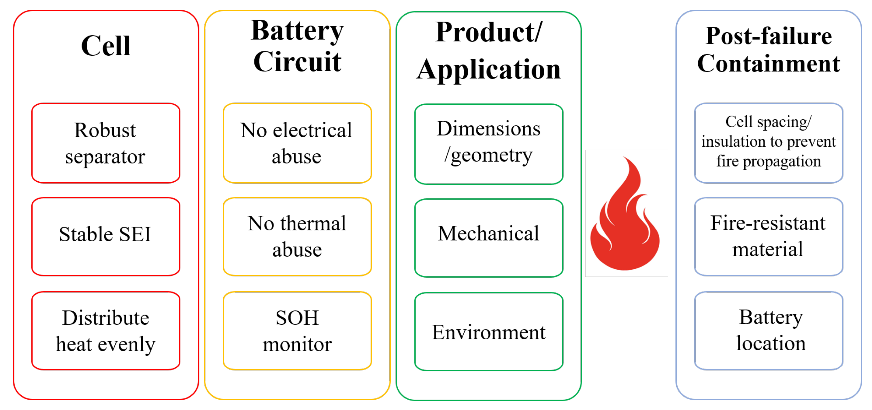
This investigation has several important limitations that should be acknowledged:
First, while our disassembly of both the failed subject insole and exemplar units revealed no apparent manufacturing defects, we cannot definitively exclude this possibility due to the severe damage sustained by the jelly roll structure during the failure event. The compromised state of the damaged components prevented conclusive assessment of potential original manufacturing flaws.
Second, the pressure-sensitive film analysis was from a short load duration (12 steps) and provided only qualitative identification. Longer time exposure might show a different stress pattern and quantification would help establish a cyclic stress-time relation for the failure.
Third, the experimental protocol did not include cyclic loading tests during discharge operations that might have reproduced the failure mode. The 12-step gait analysis was done on a discharged cell, not a fully charged cell. A charged cell would exhibit more expansion.
Finally, the study lacked comparative testing of ceramic-coated separators under identical conditions. Practical constraints prevented acquisition of customized insoles with ceramic-coated separators as the sole modified variable, which would have enabled definitive evaluation of whether such separators could withstand repetitive loading below 10% of the single-crush thresholds specified in UL 1642, IEC 62133, and UL 2054 standards.

5. Conclusions

Our investigation of a lithium-ion battery fire in heated insoles revealed a mechanical stress-induced failure during normal use. Comprehensive analysis using X-ray/CT imaging identified the ignition source at the battery’s heel-side edge, directly correlating with the area of peak cyclic stress during walking. Through material characterization, electrical testing, and thermal analysis, we confirmed that repetitive compression, not electrical or thermal factors, caused an ISC. This failure was exacerbated by three critical design flaws: (1) use of a basic polyethylene separator lacking ceramic coating; (2) absence of battery health monitoring in the circuit design; and (3) hazardous battery placement inside clothing, which amplified burn injuries.
Although this failure occurred in heating insoles, the findings reveal a broader safety concern for wearable applications. Lithium-ion batteries integrated into footwear and clothing routinely experience mechanical stresses that existing safety standards (UL 1642, IEC 62133, and UL 2054) fail to address. This discrepancy creates a dangerous scenario where products pass laboratory certification but remain vulnerable to real-world failure. To bridge this critical gap, we propose a four-tier safety framework:
1.
Cell-level robustness: Implementation of ceramic-coated separators, stable SEI formulations, and designs ensuring homogeneous heat distribution to prevent internal shorts.
2.
Smart circuit architectures: Mandatory integration of health monitoring systems to detect early degradation while preventing electrical/thermal abuse.
3.
Product specific consideration: Rigorous evaluation of placement and environmental stresses during product design.
4.
Fail-safe containment: Strategic use of fire-retardant materials, isolation designs to prevent thermal runaway propagation, and exterior placement away from skin contact.
The 12 reported insole fires, more than half of which occurred in powered-off devices, point to a systemic safety gap in the design of wearable batteries. Our analysis bridges this gap by proving that cyclic mechanical stress, not electrical or thermal abuse, can trigger thermal runaway. This paradigm shift explains why existing standards do not predict field failures and provides a roadmap to mitigate risks in not just insoles but all mechanically stressed wearables.

Supplementary Materials

The following supporting information can be downloaded at: https://www.mdpi.com/article/10.3390/batteries11070271/s1, Figure S1: FTIR results of insole’s top layer, grey and red foams, battery box, and battery separators; Figure S2: SEM and EDS of metal plate in Exemplar #1’s left insole; Figure S3: (a) SEM and EDS of anode in Exemplar #1’s left battery. (b) SEM and EDS of cathode in Exemplar #1’s left battery. (c) SEM and EDS of anode in Exemplar #2’s left battery. (d) SEM and EDS of cathode in Exemplar #2’s left battery; Figure S4: PCB for Exemplar #1, Exemplar #2, Subject, and block diagram for all PCBs. The PCB from the burned subject right insole shows severe burn damage on the lateral side (green arrow), consistent with the severe burn damage of the subject right battery cell; Figure S5: (a) Thermal test setup. Thermocouples were placed in the sole area (yellow dots) and inside the battery box underneath the battery cell. (b) (Top) Temperature profile of Exemplar #1 right insole at medium power setting with insulation. (Bottom) Temperature profile of Exemplar #1 and #2 insoles on high power setting in air without insulation; Table S1: Tests of subject and exemplar insoles.

Author Contributions

R.Y.: Methodology, Investigation, Writing—original draft. S.J.: Investigation, Writing—review and editing. G.S.: Supervision, Writing—review and editing. All authors have read and agreed to the published version of the manuscript.

Funding

This research received no external funding. This investigation originated as a failure analysis project conducted for a confidential client. To protect client confidentiality, specific brand information and identification details have been omitted. While the client only commissioned non-destructive examination as part of the original scope, the authors subsequently conducted destructive testing on both exemplar and subject insoles to complete the analysis.

Data Availability Statement

Data are contained within the article and Supplementary Materials.

Acknowledgments

The authors gratefully acknowledge Peter Lloyd for his valuable assistance in facilitating the insole testing procedures for this study.

Conflicts of Interest

All authors are employed by the company Berkeley Engineering and Research (BEAR), an engineering consulting firm that does a significant amount of litigation consulting and expert work in lithium-ion battery fire cases. The cases involving small lithium-ion batteries or cells are mostly with plaintiffs. Apart from payment received exclusively for X-ray and CT scans related to this paper, the authors declare that they have no known competing financial interests, personal relationships, or other potential conflicts (financial or non-financial relationships that could affect the objectivity of the research) that could have appeared to influence the work reported in this paper.

Abbreviations

The following abbreviations are used in this manuscript:
LIBLithium-ion battery
ISCInternal short circuit
NiMHNickel-metal hydride
BMSBattery management system
PCBProtection circuit board (sometimes printed circuit board)
SOHState of health
CTComputed tomography
SEMScanning electron microscopy
EDSEnergy dispersive spectroscopy
FTIRFourier transform infrared spectroscopy
OCVOpen-circuit voltage
PETPolyester
PEUPolyether urethane
NCMNickel-cobalt-manganese
LCOLithium cobalt oxide
PEPolyethylene
ICIntegrated circuit
PWMPulse-width modulation
SEISolid electrolyte interphase

References

  1. Nishi, Y.; Wakihara, M. Performance of the First Lithium Ion Battery and Its Process Technology. In Lithium Ion Batteries: Fundamentals and Performance; Kodansha Ltd.: Tokyo, Japan, 1998; pp. 181–198. [Google Scholar] [CrossRef]
  2. Whittingham, M.S. Lithium batteries and cathode materials. Chem. Rev. 2004, 104, 4271–4301. [Google Scholar] [CrossRef] [PubMed]
  3. Mikolajczak, C.; Kahn, M.; White, K.; Long, R.T. Lithium-Ion Batteries Hazard and Use Assessment Final Report. Technical Report, The Fire Protection Research Foundation. 2011. Available online: https://www.nfpa.org/education-and-research/research/fire-protection-research-foundation/projects-and-reports/lithium-ion-batteries-hazard-and-use-assessment (accessed on 15 May 2025).
  4. Xu, K. Nonaqueous liquid electrolytes for lithium-based rechargeable batteries. Chem. Rev. 2004, 104, 4303–4417. [Google Scholar] [CrossRef] [PubMed]
  5. Lai, X.; Jin, C.; Yi, W.; Han, X.; Feng, X.; Zheng, Y.; Ouyang, M. Mechanism, modeling, detection, and prevention of the internal short circuit in lithium-ion batteries: Recent advances and perspectives. Energy Storage Mater. 2021, 35, 470–499. [Google Scholar] [CrossRef]
  6. Kim, C.S.; Yoo, J.S.; Jeong, K.M.; Kim, K.; Yi, C.W. Investigation on internal short circuits of lithium polymer batteries with a ceramic-coated separator during nail penetration. J. Power Sources 2015, 289, 41–49. [Google Scholar] [CrossRef]
  7. CPSC Issues Consumer Safety Warning: Serious Injury or Death Can Occur if Lithium-Ion Battery Cells Are Separated from Battery Packs and Used to Power Devices. Available online: https://www.cpsc.gov/Newsroom/News-Releases/2021/CPSC-Issues-Consumer-Safety-Warning-Serious-Injury-or-Death-Can-Occur-if-Lithium-Ion-Battery-Cells-Are-Separated-from-Battery-Packs-and-Used-to-Power-Devices (accessed on 18 September 2023).
  8. ANSI/CAN/UL 8139:2020; Electrical Systems of Electronic Cigarettes and Vaping Devices. ULSE: Evanston, IL, USA, 2020. Available online: https://www.shopulstandards.com/ProductDetail.aspx?productId=UL8139_2_S_20240426 (accessed on 15 May 2025).
  9. CPSC Warns Consumers to Immediately Stop Using WOTOTIC and Ackpair Heated Socks Due to Risk of Serious Burn Injury and Fire Hazard; Sold on Amazon.com. 2024. Available online: https://www.cpsc.gov/Warnings/2025/CPSC-Warns-Consumers-to-Immediately-Stop-Using-WOTOTIC-and-Ackpair-Heated-Socks-Due-to-Risk-of-Serious-Burn-Injury-and-Fire-Hazard-Sold-on-Amazon-com (accessed on 21 June 2025).
  10. Choi, M.S.S.; Lee, H.J.; Lee, J.H. Early intervention for Low-Temperature burns: Comparison between early and late hospital visit patients. Arch. Plast. Surg. 2015, 42, 173–178. [Google Scholar] [CrossRef] [PubMed]
  11. Columbia Sportswear Recalls Batteries Sold With Jackets Due to Fire Hazard. 2011. Available online: https://www.cpsc.gov/Recalls/2011/columbia-sportswear-recalls-batteries-sold-with-jackets-due-to-fire-hazard (accessed on 21 June 2025).
  12. BRP Recalls Ski Doo and Can Am Lithium Ion Rechargeable Batteries and Heated Gloves. 2014. Available online: https://www.cpsc.gov/Recalls/2014/BRP-Recalls-Ski-Doo-and-Can-Am-Lithium-ion-Rechargeable-Batteries-and-Heated-Gloves (accessed on 21 June 2025).
  13. Tech Gear 5.7 Recalls Performance Heated Socks Due to Fire and Burn Hazards. Technical Report. 2019. Available online: https://www.cpsc.gov/Recalls/2019/Tech-Gear-5-7-Recalls-Performance-Heated-Socks-Due-to-Fire-and-Burn-Hazards (accessed on 21 June 2025).
  14. Wilford, D. Burlington Man Suffers Burns After Amazon Insoles Catch Fire. 2023. Available online: https://torontosun.com/news/local-news/burlington-man-suffers-burns-after-amazon-insoles-catch-fire#comments-area (accessed on 21 June 2025).
  15. Heated Insole Burn Injury. Available online: https://www.jasonturchin.com/practice-areas/product-liability-attorneys/consumer-product-liability/heated-insole-burn-injury/ (accessed on 21 June 2025).
  16. Hajebian, H.; chambers, C.; Murota, D.; Lodescar, R.; Turkowski, J. 647 Full Thickness Burn Injuries from Heated Insole Device Explosions: First Case Series. J. Burn. Care Res. 2025, 46, S212. [Google Scholar] [CrossRef]
  17. George, G. An Unexpected Burn. 2025. Available online: https://www.adirondackalmanack.com/2025/01/an-unexpected-burn.html (accessed on 21 June 2025).
  18. Cole-Price, A.K.; Silverman, E.; Sienko, P.; Molvik, H.; Vercruysse, G.A. An Initial Report of Thermal Runaway Resulting in Full-Thickness Foot Burns From Lithium-Ion Battery-Powered Insole. J. Burn. Care Res. 2024, 45, 1636–1640. [Google Scholar] [CrossRef] [PubMed]
  19. Quttaineh, R. Electronically Heated Insoles Leave MN Man with Third-Degree Burns, Medical Professionals Say to Stay Away from Similar Products. 2024. Available online: https://www.kare11.com/article/news/local/heated-rechargeable-apparel-products-insole-electronic-burns-hospital-center/89-78bb1397-2b41-464b-9018-c35b5308a499 (accessed on 20 June 2025).
  20. Quttaineh, R. Minnesota Man Suffers Burns After Rechargeable Insoles Explode Inside Boots. 2024. Available online: https://www.valleynewslive.com/2024/12/17/minnesota-man-suffers-burns-after-rechargeable-insoles-explode-inside-boots/ (accessed on 20 June 2025).
  21. Johnson, S. Warning: Heated Insole Malfunction, 2024. Available online: https://www.wjfw.com/news/warning-heated-insole-malfunction/article_4d0b1872-bd9b-11ef-9742-2f91c3dd4431.html (accessed on 20 June 2025).
  22. Koech, A.K.; Mwandila, G.; Mulolani, F.; Mwaanga, P. Lithium-ion battery fundamentals and exploration of cathode materials: A review. S. Afr. J. Chem. Eng. 2024, 50, 321–339. [Google Scholar] [CrossRef]
  23. UMW TP4056 1A Standalone Linear Li-Ion Battery Charger. Available online: https://www.umw-ic.com/static/pdf/493f603e988f83ce21e556bca0c516fd.pdf (accessed on 8 May 2025).
  24. UMW TP4057 1A Standalone Linear Li-Ion Battery Charger. Available online: https://www.umw-ic.com/static/pdf/a62b0c86d7543da6d2ba82f8104549b0.pdf (accessed on 16 May 2025).
  25. DW06 One Cell Lithium-Ion/Polymer Battery Protection IC Datasheet. Available online: http://www.pingjingsemi.com/UploadFile/pdf/DW06.pdf (accessed on 28 March 2025).
  26. DW07D One Cell Lithium-Ion/Polymer Battery Protection IC Datasheet. Available online: https://lcsc.com/datasheet/lcsc_datasheet_2202252130_Shenzhen-Fuman-Elec-DW07D_C89497.pdf (accessed on 28 March 2025).
  27. Cui, B.; Wang, H.; Li, R.; Xiang, L.; Du, J.; Zhao, H.; Li, S.; Zhao, X.; Yin, G.; Cheng, X.; et al. Long-sequence voltage series forecasting for internal short circuit early detection of lithium-ion batteries. Patterns 2023, 4, 100732. [Google Scholar] [CrossRef] [PubMed]
  28. Liu, Y.; Wang, L.; Li, D.; Wang, K. State-of-health estimation of lithium-ion batteries based on electrochemical impedance spectroscopy: A review. Prot. Control Mod. Power Syst. 2023, 8, 41. [Google Scholar] [CrossRef]
  29. Messing, M.; Shoa, T.; Habibi, S. Estimating battery state of health using electrochemical impedance spectroscopy and the relaxation effect. J. Energy Storage 2021, 43, 103210. [Google Scholar] [CrossRef]
  30. Dostal, C. (Ed.) Engineered Materials Handbook: Engineering Plastics; ASM International: Almere, The Netherlands, 1988; Volume 2. [Google Scholar]
  31. ASM International (Ed.) ASM Handbook Volume 1: Properties and Selection: Irons, Steels, and High-Performance Alloys, 10th ed.; ASM International: Almere, The Netherlands, 1990; Volume 1. [Google Scholar]
  32. Lee, S.Y. IoT-Based Sensor Shoes System for Gait Correction. Int. J. Electr. Electron. Res. 2022, 10, 62–68. [Google Scholar] [CrossRef]
  33. Keslar, D. DOT/FAA/TCTN-22/27 An Analysis of State of Charge in Lithium-Ion Batteries. Technical Report, Federal Aviation Administration. 2022. Available online: https://www.fire.tc.faa.gov/pdf/tctn22-27.pdf (accessed on 18 May 2025).
  34. Zhang, W.; Wei, Y.C.; Cheng, M.X.; Liu, Y.M.; Sun, H. The in-situ testing and modeling on sealing strength deterioration of lithium-ion pouch cell. Eng. Fail. Anal. 2021, 120, 105036. [Google Scholar] [CrossRef]
  35. UL 1642; Lithium Batteries, 6th Edition. ULSE: Evanston, IL, USA, 2020. Available online: https://www.shopulstandards.com/ProductDetail.aspx?productId=UL1642_6_S_20200929 (accessed on 19 September 2023).
  36. UL 2054; Household and Commercial Batteries, 3rd Edition. ULSE: Evanston, IL, USA, 2022. Available online: https://www.shopulstandards.com/ProductDetail.aspx?UniqueKey=40907 (accessed on 29 June 2025).
  37. IEC 62133-2; Secondary Cells and Batteries Containing Alkaline or Other Non-Acid Electrolytes: Safety Requirements for Portable Sealed Secondary Cells, and for Batteries Made from Them, for Use in Portable Applications. Part 2, Lithium Systems. IEC: Geneva, Switzerland, 2017. Available online: https://webstore.iec.ch/en/publication/32662 (accessed on 15 May 2025).
  38. UN 38.3; Lithium metal, lithium ion and sodium ion batteries. In Manual of Tests and Criteria, 8th Edition. UNECE: New York, NY, USA, 2023; pp. 426–442. Available online: https://unece.org/sites/default/files/2024-09/ST_SG_AC.10_11_Rev.8e_WEB.pdf (accessed on 29 June 2025).
  39. UL 2271; Batteries for Use In Light Electric Vehicle (LEV) Applications, 3rd Edition. ULSE: Evanston, IL, USA, 2023. Available online: https://www.shopulstandards.com/ProductDetail.aspx?UniqueKey=45051 (accessed on 29 June 2025).
  40. UL 2580; Batteries for Use In Electric Vehicles, 3rd Edition. ULSE: Evanston, IL, USA, 2020. Available online: https://www.shopulstandards.com/ProductDetail.aspx?UniqueKey=48504 (accessed on 29 June 2025).
Figure 1. Fire triangle in lithium-ion batteries.
Batteries 11 00271 g001
Figure 2. X-ray images of subject and exemplar insoles. The subject insoles (identical to Exemplar #1) feature a metal backing plate beneath the battery, while Exemplar #2 insoles use a differently sized battery and PCB without a metal plate.
Batteries 11 00271 g002
Figure 3. (a) Disassembled exemplar right insole showing battery placement between gray and red foam layers within the battery case. (b) Exemplar #1’s battery case includes a metal backing plate below the battery.
Batteries 11 00271 g003
Figure 4. Layer-by-layer illustration of insole materials and construction.
Batteries 11 00271 g004
Figure 5. Current profile or high, medium, and low power settings, respectively. The circuit maintains consistent current amplitude but varies duty cycles: high setting (100%), medium setting (70%) cycles 0.7 s on/0.3 s off; low setting (40%) cycles 0.4 s on/0.6 s off.
Batteries 11 00271 g005
Figure 6. Walking Sequence: with one foot on the ground, the other foot experiences (a) heel off, (b) foot in the air, (c) heel on the ground, and (d) whole foot on the ground.
Batteries 11 00271 g006
Figure 7. Pressure film shows high stress on the lateral side of the right foot, toward the heel end for (a) Exemplar #1 insole and (b) Exemplar #2 insole. In Exemplar #1 insole, the lateral high stress location (indicated by cyan region) overlaps with the positive (cathode) tab of the battery cell. (c) In Exemplar #1 right insole, X-ray imaging shows the negative tab of the battery cell aligns with the medial edge of the plate and the positive tab of the battery cell aligns with the lateral edge of the plate. (d) The corresponding photo of the battery for Exemplar #1 right insole, where the negative tab and positive tab are located.
Batteries 11 00271 g007
Figure 8. CT scan of the subject’s right insole reveals: (a) A metal plate beneath the battery cell and PCB. The failure (red arrow) originated at the lateral heel end. (b) Cross-sectional view of the battery, showing ignition at the positive tab (red arrow, consistent with (a)). (c) Jelly roll of the subject battery cell, with fire initiation (red arrow, same as (a)) at the inner positive tab location.
Batteries 11 00271 g008
Figure 9. Failure characteristics of the subject left insole’s battery. (a) CT reconstruction showing localized swelling and casing perforation (red arrow) in the lateral-heel region. (b) Photograph of the battery case exhibiting visible swelling compared to new exemplar batteries, with deeper mechanical compression marks (green arrows) on the lateral versus medial edges. The red box highlights a perforation and cracks in the casing, consistent with the CT findings. (c) Jelly roll (without aluminum casing) revealing a perforation and longitudinal crack in the aluminum foil. (d) Magnified view of the perforation and crack shown in (c).
Batteries 11 00271 g009
Figure 10. Structural composition and failure characteristics of the subject battery’s jelly roll. (a) Schematic shows the vertical stack configuration with separator (top), anode-coated copper foil, separator and cathode-coated aluminum foil (bottom). (b) Unrolled jelly roll exhibits discoloration of anode, separator, and (c) cathode materials at the high-stress region identified through gait analysis. The perforation observed in the CT scan is a physical crack in the cathode-coated aluminum foil.
Batteries 11 00271 g010
Figure 11. Root cause analysis of this case study.
Batteries 11 00271 g011
Figure 12. (a) Comparison of repetitive load in this case and the single crush load defined in UL 1642 [35], IEC 62133 [37] and UL 2054 [36] (b) Battery placement outside boot. Image generated by ChatGPT-4o.
Batteries 11 00271 g012
Figure 13. Four layers for safe design of batteries for a product.
Batteries 11 00271 g013
Table 1. CPSC recalls of wearables using LIBs.
DateWarning No.ProductReasonOutcome
16 November 2011 [11]12-705LIBs for heating jacketsOne report of a battery
overheating at a distribution
facility in France. No
incidents or injuries.
Renounced
25 February 2014 [12]14-115Heated gloves and
replacement LIBs
Three reports of batteries
overheating while charging.
No injuries.
Recalled
1650 units
14 March 2019 [13]19-082Heated socksFour reports of batteries
overheating, melting or
igniting. No injuries.
Recalled
4000 units
24 October 2024 [9]25-022Heated socksSeven reports: four reports of
fire and three reports of sparking
or malfunctioning.
Table 2. Fire and burn injuries caused by heating insoles since 2023.
Date of IncidenceGenderUse HistoryDevice
on?
ActivitySide of Injury
22 December 2023 [14]Male OffWalking at workLeft
28 December 2023 [15]Male OffConstruction work
at job site
Left
14 January 2024 a [14] Off
25 January 2024
(this case)
MaleNew, used fewer
than 10 times over
13 workdays
OffStepping down
at work
Right
December 2023 to
February 2024 [16]
Male Operating cons-
truction vehicle
Right
Male Using lawn mowerRight
Male Fire in snow bootRight
5 April 2024 [17]MaleSeveral pairs used
for 2 years
OffWalking to
chicken coop
Right
10 August 2024 b [18]MaleNew, used a few timesOffAt football game
tailgate party
Right
30 November 2024 [19]MalePurchased in
November 2023;
used for winter 2023;
first use in winter 2024.
Sitting during huntingLeft
12 December 2024 [20]MalePurchased in 2023, used
in winter 2023 for
hunting and fishing.
OffPreparing to put a
fish house on lake
Right
14 December 2024 [21]MaleChristmas gift in 2023,
used in winter 2023
for ice fishing.
OffPacking up fishing gear
a Comment by “Jane Fraser” in the reference. b Reflects the journal publication date, not the incident date.
Table 3. Comparison of Exemplar #1 and #2’s battery cells.
DimensionElectricalMaterial
Form FactorNominal
Voltage (V)
Capacity (mAh)Internal
Resistance (mΩ)
CathodeAnodeSeparator
Ex #16050803.7350026NCM 40/15/45GraphitePE
Ex #25352653.8300045LCOGraphitePE
Table 4. Comparison of PCBs and test of maximum charging open circuit voltage (OCV) and discharging cutoff OCV.
Cell PropertiesPCB ICTest Result
CathodeNominal
Voltage (V)
Battery Protection ICCharging Module ICCharge Max
OCV (V)
Cutoff
OCV (V)
Ex #1NMC 40/15/453.7DW06D [25]
2.4∼4.3 V
UMW TP4056 [23]
I 1 A, V 4.242 V
4.223.17
Ex #2LCO3.8DW07D [26]
2.9∼4.4 V
UMW TP4057 [24]
I 0.5 A, V 4.282 V
4.303.31
Table 5. Heating test results of exemplar right insoles.
Starting
@ 19 °C
SettingInsulationDuration
(Hours)
Insole Max
Temperature
(°C)
Cell Max
Temperature
(°C)
Cell Internal
Impedance
(m Ω )
Ex #1MediumYes0.3574.220.526
HighNo5.957.626.6
Ex #2HighNo4.655.930.145
Table 6. Exemplar batteries after charge-discharge cycling test.
InsoleTestInitial Impedance
(mΩ)
Final Impedance
(mΩ)
Swelling?
Subject
Left
Walking, <10 cyclesShould be the same
as Ex #1, ∼25
36Yes
Ex #112 steps, 10 cycles2628No
Ex #212 steps, 10 cycles4548No
Disclaimer/Publisher’s Note: The statements, opinions and data contained in all publications are solely those of the individual author(s) and contributor(s) and not of MDPI and/or the editor(s). MDPI and/or the editor(s) disclaim responsibility for any injury to people or property resulting from any ideas, methods, instructions or products referred to in the content.

