Article

Interfacial Layer (“Interlayer”) Addition to Improve Active Material Utilisation in Lithium–Sulfur Batteries: Use of a Phenylsulfonated MWCNT Film

1
School of Chemistry and Chemical Engineering, University of Surrey, Guildford GU2 7XH, UK
2
School of Mechanical Engineering Sciences, University of Surrey, Guildford GU2 7XH, UK
*
Author to whom correspondence should be addressed.
Batteries 2025, 11(7), 266; https://doi.org/10.3390/batteries11070266
Submission received: 28 May 2025 / Revised: 2 July 2025 / Accepted: 4 July 2025 / Published: 16 July 2025

Abstract

Films of functionalised multiwalled carbon nanotubes (MWCNTs) were fabricated as interlayers (interfacial layers between the cathode and separator) in a lithium–sulfur battery (LSB). Phenylsulfonate functionalisation of commercial MWCNTs was achieved via diazotisation to attach lithium phenylsulfonate groups and was characterised by IR and XPS spectroscopies. SEM-EDX showed sulfur and oxygen colocations due to the sulfonate groups on the interlayer surface. However, CHNS elemental microstudies showed a low degree of functionalisation. Without an interlayer, the LSB produced stable cycling at a capacity of 600 mA h g−1sulfur at 0.05 C for 40 cycles. Using an unfunctionalised interlayer as a control gave a capacity of 1400 mA h g−1sulfur for the first cycle but rapidly decayed to the same 600 mA h g−1sulfur at the 40th cycle at 0.05 C, suggesting a high degree of polysulfide shuttling. Adding a lithium phenylsulfonated interlayer gave an initial capacity increase to 1100 mA h g−1sulfur that lowered to 800 mA h g−1sulfur at 0.05 C by the 40th cycle, showing an increase in charge storage (33%) relative to the other cells. This performance increase has been attributed to lessened polysulfide shuttling due to repulsion by the phenylsulfonate groups, increased conductivity at the separator-cathode interface and an increase in surface area.

Graphical Abstract

1. Introduction

Lithium–sulfur batteries (LSBs) have a theoretically high specific energy, reaching 2567 W h kg−1, which is due to the high specific capacity afforded to sulfur cathodes (1675 mA h g−1sulfur) at high active material loadings (≥70%mass sulfur) [1,2]. However, the achievable specific capacities and cycle stability are lower than that predicted theoretically from the lithium–sulfur electrochemistry. While currently inferior to the cost-effectiveness and cycle stability of lithium-ion batteries (LIBs), LSB improvement paves the way for a future after LIBs/in tandem with LIBs. The most effective applications of LSBs are, therefore, applications that are gravimetrically limited such as in aircraft and spacecraft, owing to their need to be lightweight [3].
LSBs are assembled in the fully charged state, with sulfur in the S8 form, which is reduced to Li2S in the fully discharged state [4]. However, this is not a trivial process due to the 16-electron conversion and the series of phase transformations that occur. Elemental sulfur (S8) is a non-polar, electrically non-conductive, and insoluble material in common LSB (ether/carbonate-based) electrolytes, and, conversely, lithium sulfide (Li2S) is highly polar but also electrically non-conductive and insoluble in the same LSB electrolytes. This low conductivity can be surmounted by adding components that assist with charge mediation, such as electrically conductive carbonaceous materials [5].
During discharge from S8 to Li2S, the active material undergoes conversion through various lithium polysulfide species (Li2Sn, where 3 ≤ n ≤ 8) as well as lithium disulfide (Li2S2). Lithium disulfide is only slightly soluble in organic electrolytes and exhibits properties similar to lithium sulfide [6,7]. Polysulfides, by comparison, have covalent bridging sulfur (SB0) bonds between two sulfur atoms in a chain as well as charged sulfur chain termini (ST1−), and this mix of ionic and covalent centres makes these molecular ions polar, electronically conductive and soluble in ether/carbonate-based electrolytes [8,9]. This rapid increase in cathode material solubility can allow migration of the active material from the cathode to the electrolyte and separator across to the anode, that migration infamously known in the battery community as the polysulfide shuttle [10]. If these polysulfides continue past the separator, and react and deposit on the anode, the capacity is lowered, and the cycling stability is threatened due to the internal chemical short circuit [11].
It is, however, well established that LSB performance can be improved by the addition of various films and coatings to the surface of a cell’s cathode [12,13]. Carbonaceous interlayers typically have three modi operandi: improving the cathode surfaces’ conductivities through charge mediation, modifying the polarity of the cathode surface during cycling, or a moderation of surface polarity and surface conductivity improvements [14]. Such interlayers facilitate performance enhancements via a greater utilisation of active material, greater cycling stability or both [12].
Carbon nanotubes (CNTs) are high-surface-area conductive nanomaterials. Decorating CNTs with functional groups (to make the CNT surfaces polar) prior to fabrication into a film could add much-needed polarity at the cathode–separator interface as well as imparting additional conductivity at the cathode surface [15]. Table 1 provides a summary of different literature works where functionalised carbons were used in the assembly of LSBs, including the format of the addition, the type of functionalisation and synthesis technique, and the specific capacities obtained and the improvements relative to the control cells. However, the electrolyte-to-sulfur (E/S) ratios used are typically very large and, consequentially, are often omitted from published works (as seen in Table 1).
Lithium phenylsulfonate groups can be added to carbon surfaces by diazotisation of sulfanilic acid, with heating to decompose the in situ formed diazonium salt and subsequent work-up with lithium hydroxide to deprotonate the sulfonic acid group [16]. Lithium sulfonate functionalisation of the porous carbon sulfur-host has been shown to hinder the polysulfide-shuttle effect [17]. A phenylsulfonate group is thought to be even more beneficial than a sulfonate group as the aromatic ring enhances the sulfonic acid’s pKa from −1.9 (as R-CH2SO3H) to −2.8 (as R-C6H4SO3H), leading to greater acidity and dissociation, as well as being large groups which theoretically can size exclude polysulfide losses to a better extent [18].
Table 1. A literature review comparison of functionalised carbonaceous materials added in the assembly of lithium–sulfur batteries. The comparison includes the format of the carbon addition, the type of functionalisation added and its method of addition, the discharge improvement and the C-rate of the improvement, if the E/S ratio of the cell is given, and the associated reference of the work.
FormatFunctionalisationMethod of AdditionCell Capacity
(mA h g−1sulfur)
Improvement
(mA h g−1sulfur)
C-Rate (h−1)Refs
CathodeMethylsulfonationStrecker sulfite
alkylation
~820 (@ 100th cycle)+ ~270 (@ 100th cycle)0.1[17]
CathodePEI +Grafted to CNT surface~750 (@ 100th cycle)+ ~350 (@ 100th cycle)0.5[19] *
CathodeN-doped CNTs grown on Co3O4Spray pyrolysis on Co3O4~700 (@ 400th cycle)+ ~460 (@ 400th cycle)1.0[20] *
CathodeN-dopedMelamine addition during polymerisation~963 (@ 100th cycle)+ ~281 (@ 100th cycle)1.0[21] *
Cathode/
Interlayer
O or H-dopingAnnealing~750 (@ 250th cycle)+ ~480 (@ 250th cycle)0.5[22] *
Separator coatingPhenylsulfonationDiazotisation of rGO ‡ with sulfamic acid ~930 (@ 100th cycle)+ ~286 (@ 100th cycle)0.5[23] *
Separator coatingrGO ‡-PEDOT:PSS ◊Air-controlled
Electrospray
~813 (@ 100th cycle)+ ~516 (@ 100th cycle)0.5[24] *
Separator coatingMixing with PANi 0Filtering a dispersion~400 (@ 50th cycle)+ ~50 (@ 50th cycle)0.2[25] *
* E/S (μL mg−1sulfur) omitted and/or missing values to calculate from other parameters. + Polyethylenimine. 0 Polyaniline. † Nanofiber. ‡ Reduced graphene oxide. ◊ Poly(3,4-ethylenedioxythiophene):polystyrene sulfonate.

2. Materials and Methods

2.1. Chemicals and Electrolyte Composition

The sulfur-hosts used in this study were porous carbons that were derived from resole-type phenol-formaldehyde resins; synthesis conditions are fully discussed and specified in our previous paper [26]. The starting chemicals used in this study were phenol (99%, ACS grade, Merck, London, UK); formaldehyde (37% in water [10% methanol], ACS grade, Merck); lithium carbonate (99%, ACS grade, Merck); CTAB [cetyltrimethyl ammonium bromide] (98%, Alfa Aesar, Lancashire, UK); hydrochloric acid (37% in water, Fisher, Leicestershire, UK); sulfur (99.98%, Merck); oxalic acid dihydrate (99%, ACS grade, Merck); ammonium thiosulfate (98%, Merck); MWCNTs [multiwalled carbon nanotubes] (95+% carbon content, 3100 thin MWCNTs, Nanocyl, Sambreville, Belgium); Triton X-100 (laboratory grade, Merck); ethanol (absolute, Fisher); sulfanilic acid (99%, ACS grade, Sigma-Aldrich, Dorset, UK); sodium nitrite, NaNO2 (97+%, ACS grade, Sigma-Aldrich); sulfuric acid (at least 95%mass, Fisher); lithium hydroxide monohydrate (98%, Thermoscientific, Leicestershire, UK); Super P® carbon (Timcal, Congleton, UK); NMP [N-methyl 2-pyrolidone] (99%, anhydrous, Merck); PVDF [polyvinylidene difluoride] (~534,000 molecular weight by GPC, Merck); lithium ribbon (99.9, 0.75 mm thick, Merck).
The electrolyte was dissolved in a solvent mixture of 50:50 v/v of DME [1,2-dimethoxyethane] (99.5%, anhydrous, inhibitor-free, Merck) and DOL [1,3-dioxolane] (99.8%, with 75 ppm BHT [butylated hydroxytoluene] inhibitor, anhydrous, Merck); each solvent was dried using molecular sieves (4 Å, 8–12 mesh, Merck). LiTFSI [lithium bis(trifluromethanesulfonyl)imide] (99.95%, Merck) had been dried for 3 days at 120 °C on a Schlenk line before dissolving in the mixed solvents at to a concentration of 1.0 mol dm−3. Lithium nitrate (99.99%, Merck) had also been dried in a vacuum oven overnight at 80 °C. This was added to the electrolyte to a 0.8 mol dm−3 concentration. The filtration membrane used was 0.22 μm pore PVDF membrane (Merck).
The cathode current collector was a carbon-coated aluminium foil (MTI Corporation). Coin cell (2032 format) assembly used stainless-steel 304 components with Celgard 2400 polypropylene film separator membrane.

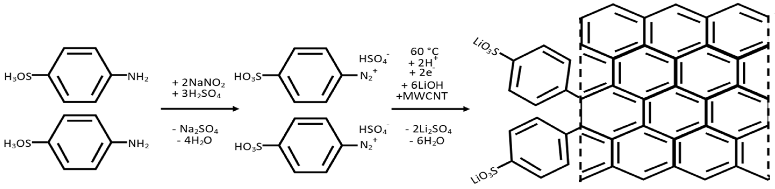
2.2. Functionalisation of Multiwalled Carbon Nanotubes

A quantity of 60 mg of multiwalled carbon nanotubes (MWCNTs) was weighed into a round-bottomed flask in a high-efficiency particulate air (HEPA)-filtered fume hood, and 3.46 g sulfanilic acid and 1.38 g sodium nitrite (NaNO2) were added.
The mixture was magnetically stirred to mix the powders with a stopper in place. The stopper was then removed and 10 cm3 of concentrated sulfuric acid was next added dropwise. After the highly exothermic acidification step, the black paste cooled for 20 min, and the paste was then stirred at 60 °C for 1 h (Figure 1).
When cooled, the paste was vacuum-filtered using a PVDF membrane (0.22 μm) and washed with acetone. Washing was continued until the filtrate passed through the membrane clear and colourless. The modified MWCNTs were washed with 100 cm3 of 1.0 mol dm−3 lithium hydroxide to remove aqueous impurities and neutralise surface sulfonic acid groups, followed by deionised water. The functionalised MWCNTs were collected (while still damp) and ultrasonicated (stainless-steel sonic horn till) for 30 min in 80 cm3 of deionised water to form a homogeneous dispersion.

2.3. Fabrication of a Functionalised MWCNT Interlayer Film

Once ultrasonicated, the dispersion above was re-filtered through fresh PVDF membrane and washed with 50 cm3 lithium hydroxide (1 mol dm−3) to further allow conversion of the sulfanilic acid groups to lithium sulfonate groups. After leaving to dry on the pumped Buchner funnel for a further 2 h, the entire PVDF membrane (topped with a thin and even layer of MWCNTs) was dried overnight in an oven at 40 °C. The PVDF membrane was subsequently peeled away, yielding a film of functionalised MWCNTs.

2.4. Fabrication of an Unfunctionalised MWCNT Interlayer Film

As a control, a film of unfunctionalised MWCNTs was made by dispersing 60 mg MWCNTs in 1%mass aqueous Triton X-100 and sonication as above for 30 min. The homogeneous dispersion was vacuum-filtered as before, and the filtrate was washed using deionised water and ethanol to remove the Triton X-100 surfactant. The MWCNT film was dried in an oven at 40 °C overnight, followed by removal of the PVDF membrane to reveal a self-supportive film of unfunctionalised MWCNTs with a thickness of ~100 µm.
Circular cuttings (14 mm diameter, with masses of ~3 mg) of the carbon films (functionalised and unfunctionalised) were used in electrochemical studies of lithium–sulfur coin cells, the films being placed between the cathode (the syntheses of which were given in previous work) and the separator membrane in each case [26].

2.5. Cell Production

The cathodes were a composition of sulfur, porous carbon (Reg-600, see previous work), Super P® and PVDF of 70:10:10:10 (%mass), respectively [26]. The porous carbon and sulfur were in the form of a 1:7 mass composite (by melting or depositing [via thiosulfate acidification] the sulfur into the carbon) of porous carbon (pyrolysed resole) to sulfur. This, in turn, would constitute 80%mass of the final coating. The super P® conductive additive was as a 4.2%mass ink that was dispersed using NMP (10%mass of the dried film) [26]. The coatings were applied to a carbon-coated aluminium foil and dried to a thickness of 400 µm followed by vacuum-drying at 50 °C overnight. The resulting cathodes were cut to 14 mm diameter discs, at areal loadings of sulfur of 2.1–3.7 mgsulfur cm−2, to be used in CR2032 coin cells.
Cell assembly: All cell assembly occurred in an MBRAUN UNIlab pro dry box that was in an argon atmosphere (H2O and O2, both <0.1 ppm). CR2032 coin cells (with 304 stainless-steel casing, spring and spacer) used lithium electrodes with a 14 mm diameter, and a 16 mm diameter Cellgard 2400 membrane was placed atop the lithium. The electrolyte was syringed on the separator at a project-specific (the Faraday Institution’s LiSTAR project) E/S ratio of 10 µL mg−1sulfur, based on the sulfur content on the cathode coating irrespective of interlayer addition (i.e., 10 µL mg−1sulfur for cells assembled with or without an interlayer). The electrolyte used was a 50:50 v/v DOL to DME, with 1.0 mol dm−3 LiTFSI and 0.8 mol dm−3 LiNO3. MWCNT films were added between the cathode and the separator. Cells were crimp-sealed within the dry box.

2.6. Characterisation

Materials characterisation: Raman spectroscopy was conducted on a Thermo Scientific DXR Raman microscope using a 532 nm excitation laser (6 mW power setting) and a grating with 900 lines mm−1 at 5 cm−1 resolution. Every spectrum was taken as an average of ten 1 s accumulations. All spectra were baseline corrected and normalised to the carbon G band at 1592 cm−1. Spectral transformations used Spectragryph (version 1.2.16.1) software.
X-ray diffraction (XRD) profiles were taken with the use of a Malvern Panalytical X’pert powder diffractometer; the recording conditions were 2 h measurements between 10° ≤ 2θ ≤ 70° at 40 mA and 45 kV with a Cu Kα radiation source. X-ray photoelectron spectroscopy (XPS) results were taken with the use of a Thermo Scientific K-Alpha+ spectrometer (UK) using a monochromatic Al Kα (hν = 1486.6 eV, where 1 eV = 96.487 kJ mol−1) X-ray source; the spot had an approximate radius of 400 µm. All survey spectra used a 200 eV pass energy, and each core level spectrum used a 50 eV pass energy. Core level spectra were corrected for charging effects by charge referencing relative to the C1s peak at 285.0 eV.
Infrared (IR) spectra were recorded using a PerkinElmer Spectrum Two FT-IR spectrometer (UK) with the use of a diamond/ZnSe UATR accessory. Each spectrum consisted of an average of 32 Fourier transform (FT) scans, at 2 cm−1 resolution between 4000–400 cm−1. All scanning electron microscopy (SEM) images studied samples with a 3 nm gold coating were recorded on a Thermo Scientific Apreo S electron microscope (UK) that used a secondary electron detector, at a 1.6 nA current and 5 kV energy. Elemental mapping utilised an energy-dispersive X-ray (EDX) detector (UK). Nitrogen sorptiometry for porosity and specific surface area studies was undertaken at 77 K using a Belsorp mini II (UK) soptiometer (UK). Elemental microanalysis (CHNS studies) was performed with a Thermo Scientific Thermo FlashEA 1112 in a helium environment following dynamic flash combustion (DFC) gas at 1800 °C; separation and quantification of the vaporised products was performed with a gas chromatography (GC) column and a thermal conductivity detector (TCD), respectively.
Electrochemical studies: Galvanostatic discharge–charge (GDC) cycling at 0.05 C was operated within 1.8–2.8 V window using a Solartron SI 1470E potentiostat (UK). All currents were solely based on the active material in the cathode; any added interlayer bore no influence on the applied GDC currents. Electrochemical impedance spectroscopy (EIS) was achieved on a Solartron SI Cell (UK) Test 1400 unit (1455A frequency response analyser channels) working in union with the Solartron SI 1470E potentiostat (UK). Potentiostatic EIS was carried out over the frequency range 1 MHz–10 MHz; the perturbation was 5 mVrms at the open circuit voltage (OCV).

3. Results and Discussion

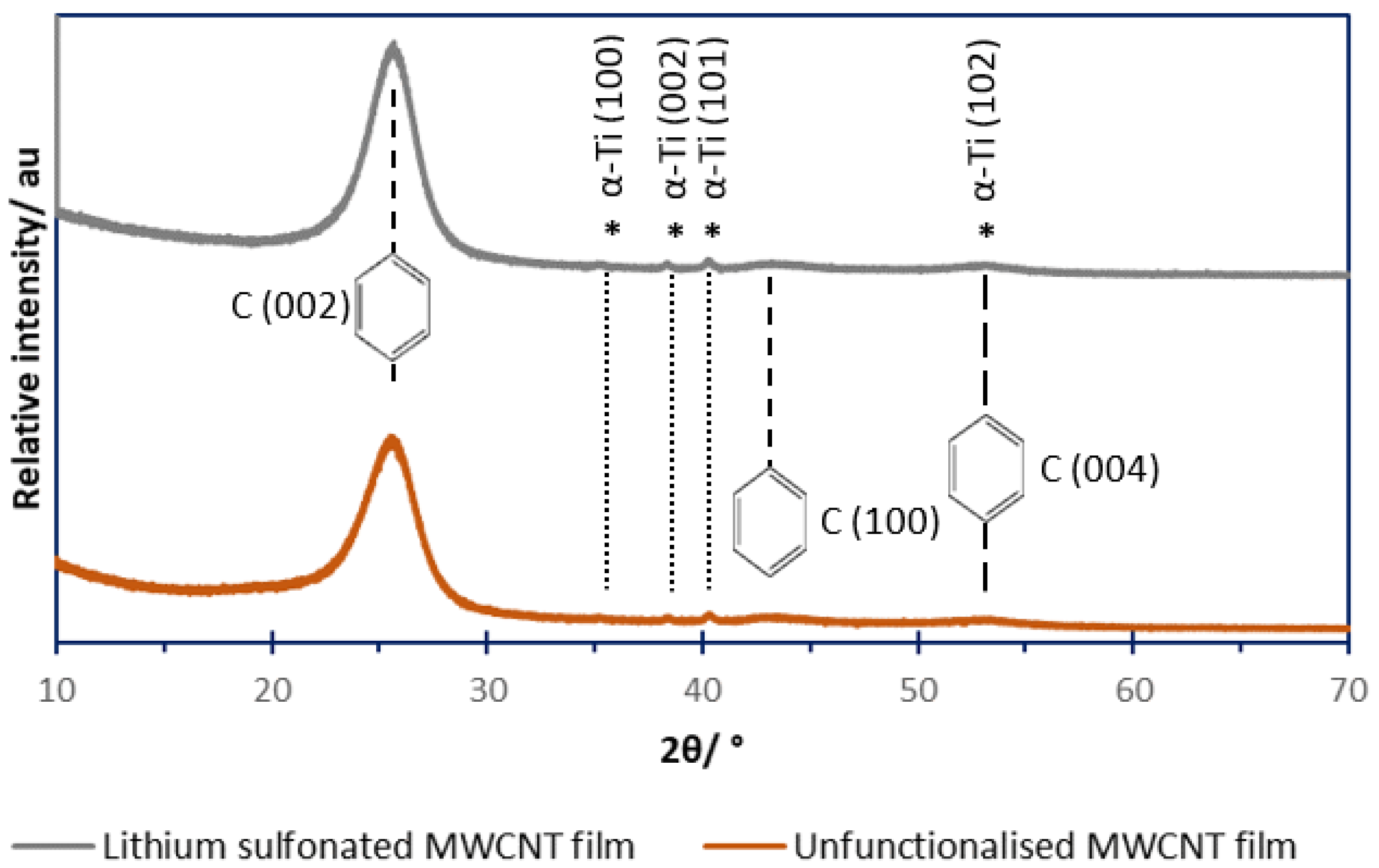
3.1. Powder X-Ray Diffractometry (XRD)

A lithium phenylsulfonate functionalised MWCNT film was studied as an LSB interlayer placed between the cathode and separator. A control unfunctionalised MWCNT film was also fabricated. Figure 2 shows XRD diffraction profiles of both films and shows no discernible difference between their profiles. The two key features in both are broad peaks at 26° and 44° of 2θ (signified by the aromatic rings), corresponding to the (002) and (100) crystal planes of elemental carbon, respectively [27]. Instead of the sharp peaks given by high-crystallinity elemental carbon, the peaks are broad due to the nanoscale dimensions of the MWCNTs [28].
The profiles in Figure 2 both show very low-intensity peaks at 35.2°, 38.3°, 40.2° and 53.2° of 2θ (signified by the asterisks); these peaks are also present for the commercially available MWCNTs (Nanocyl) before functionalisation, and the peaks are consistent with a low content of elemental titanium metal (α-phase, hexagonal). Titanium surfaces are frequently used in the synthesis of CNTs through anodising a titanium growth substrate for CNTs, which is subsequently etched away [29].

3.2. Nitrogen Sorptiometry

Figure 3 shows the N2 sorption–desorption isotherms at 77 K for the MWCNT films; the films themselves were studied because the parent nanomaterial powders would not accurately reflect the film’s surface area or porosity. The isotherms of both films are Type IV with H1 hysteresis, which characterises both films as mesoporous (with pores with 2 < pore diameter (nm) < 50) and with pores of cylindrical shape. The modelled porosity data are given in Figure S1 (Supplementary Information).
Modelling from the literature suggests that micropores are effective at polysulfide adsorption relative to mesopores, yet, for this interlayer, application pores that have small diameters would theoretically be ineffective [30,31]. When the interlayer is placed between the cathode and separator of an LSB, the film ideally should provide large enough mesopores to permit migration of the solvent (both DOL and DME) and solvated lithium ions.
Using a model based on Brunauer–Emmett–Teller (BET) theory, the specific surface areas (computed using the typical mesoporous range of 0.05–0.35 P/P°) are shown in Table 2. The functionalised MWCNT film showed a lower specific surface area relative to the unfunctionalised MWCNT film. This provides indirect evidence of the functionalisation (grafted polar lithium phenylsulfonate groups), which improved MWCNTs’ dispersibility in water without the use of surfactant (that additive was needed in the case of the dispersion of unfunctionalised MWCNTs). The better dispersed solution produced a film with a lower specific surface area because of less interstitial large mesoporosity and less microporosity [32]. The lower specific surface area observed for the lithium sulfonated MWCNT film was attributed to more agglomerations and bundles of MWCNTs in dispersion in aqueous media, relative to the unfunctionalised film, which used a Triton X-100 surfactant in its synthesis [33].

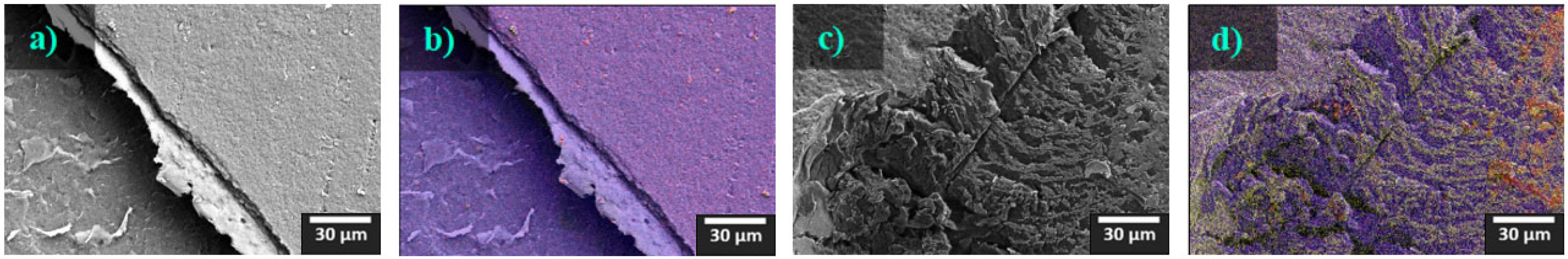
3.3. Scanning Electron Microscopy (SEM)

Figure 4 shows SEM micrographs relating to the unfunctionalised MWCNT film (a and b) and those relating to the lithium phenylsulfonated MWCNT film (c and d). Since both MWCNT films consist of carbon nanotubes, the predominant element detected is carbon (given by blue in the EDX maps), and the carbon presence is shown as a widely distributed expanse of carbon. The red and yellow false-colourings of EDX mapping images in Figure 4b,d are due to oxygen and sulfur colocations on the surface of the functionalised film that are not present on the unfunctionalised film; oxygen and sulfur are within the functional groups of the lithium sulfonated MWCNT films. Figure 4c,d show the functionalised film with a dark blue (carbon) heterogeneity defect formed during sample preparation for SEM. The defect exposes the lower carbon tape that was used to fix the sample to the SEM sample stub. This shows and contrasts the extent of functionalisation.

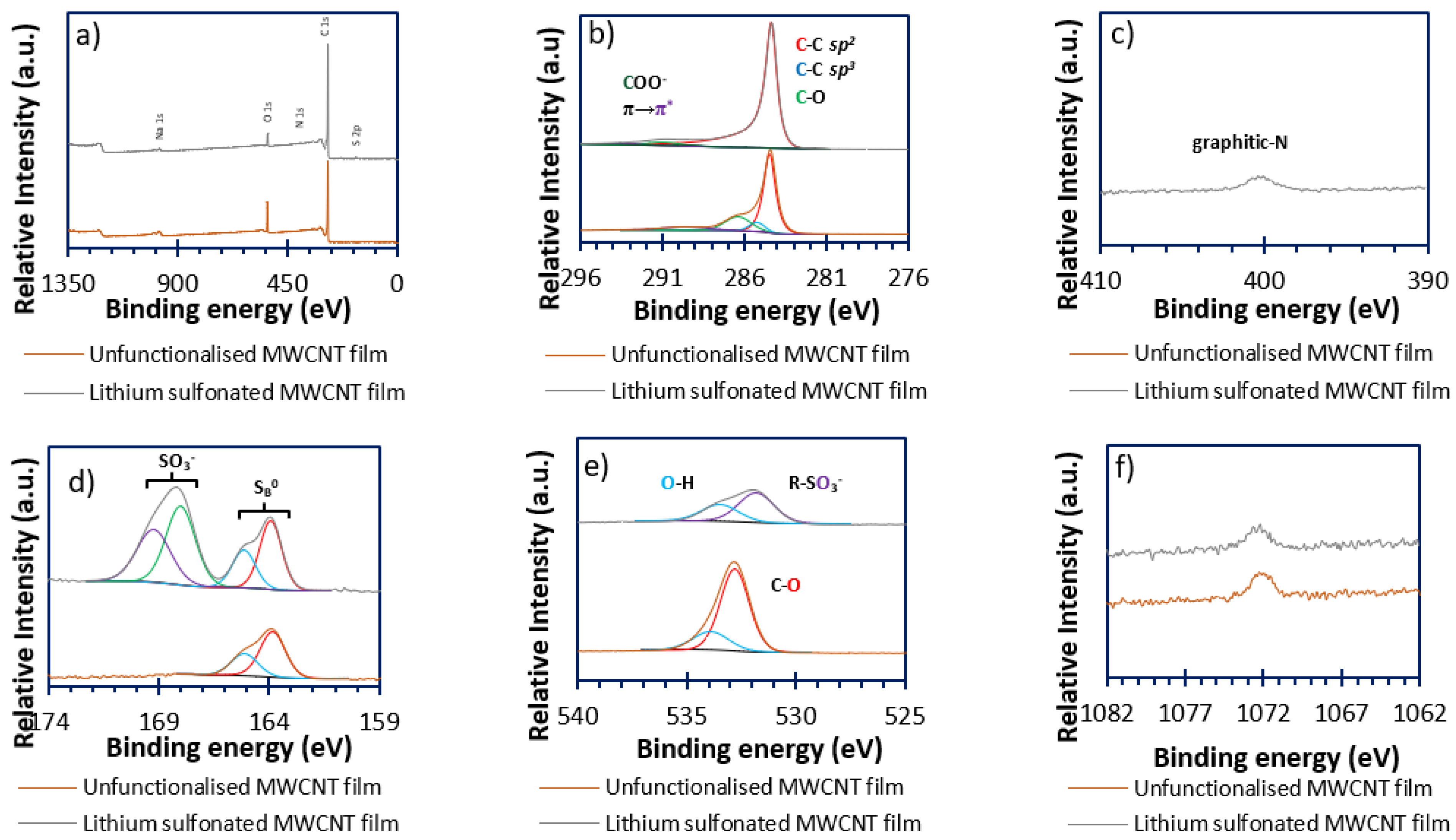
3.4. X-Ray Photoelectron Spectroscopy (XPS)

Figure 5 shows the XPS spectra for each film type. Figure 5a is the survey spectrum. Changes occur in element-specific spectra before and after functionalisation, especially the sulfur and oxygen high-resolution spectra present in Figure 5d and Figure 5e, respectively.

3.4.1. Carbon (Figure 5b)

The spectrum for the unfunctionalised MWCNT film gives a major peak at 284.5 eV and a minor peak at 286.6 eV for the film of unfunctionalised MWCNTs; those peaks correspond to aromatic sp2-type carbon (expected for CNTs) and C-O bonds, respectively [34,35]. After functionalisation, the minor peak is no longer visible, and the same major peak persists, which may suggest that the added functionality eclipses the previously detected C-O bonds. The fact that, following the surface functionalisation, the major carbon peak associated with the surface is unchanged at 284.5 eV (corresponding to aromatic sp2-type carbon), rather than shifting to a binding energy closer to 285.0 eV (corresponding to sp3-type carbon), could suggest a very light degree of functionalisation. However, this may also reflect that the added lithium sulfonate functional groups also contain a phenyl (sp2-carbon/aromatic) ring. Closer inspection of the fitted peaks for carbon XPS spectra are shown for both MWCNT films in Figure S3.

3.4.2. Nitrogen (Figure 5c)

The unfunctionalised MWCNT film shows no detectable nitrogen presence, but, following the diazotisation reaction, the functionalised MWCNT film has a nitrogen peak–the MWCNT film has been azotised, introducing C-N bonds. The peak at 401.0 eV (assigned to graphitic C-N bonds) was thought to be added as a by-product during the multi-stage functionalisation [36].

3.4.3. Sulfur (Figure 5d)

Prior to surface functionalisation, the sulfur-specific peaks are consistent with bridging/elemental sulfur’s (SB0) 2p1/2 and 2p3/2 peaks at 165.2 and 164.0 eV [37]. Yet, following the functionalisation, these peaks coexist with another set of peaks at 168.9 and 167.7 eV, corresponding to 2p1/2 and 2p3/2 of added sulfonate groups on the interlayer’s surface [38].

3.4.4. Oxygen (Figure 5e)

The oxygen-specific peak of the unfunctionalised film gave a single peak at 532.5 eV with a shoulder at 533.6 eV, which were assigned to carbonyl/carboxyl C-O groups and carboxyl and alcohol O-H groups (also shown in the carbon-specific peaks), respectively [39]. However, once functionalised, these peaks are replaced by a major peak corresponding to sulfonate groups’ S-O bonds at 531.6 eV and a minor shoulder at 533.6 eV, consistent with carboxyl and alcohol O-H groups [40].

3.4.5. Sodium (Figure 5f)

The high-resolution sodium spectra also show peaks at 1072.3 eV as Na+ impurities in the unfunctionalised MWCNT, as well as the MWCNTs following functionalisation, implying that this impurity predates functionalisation using sodium nitrite to form nitrous acid for the formation of the diazonium ion in situ [41]. Elemental surface concentrations are given in Table 3.

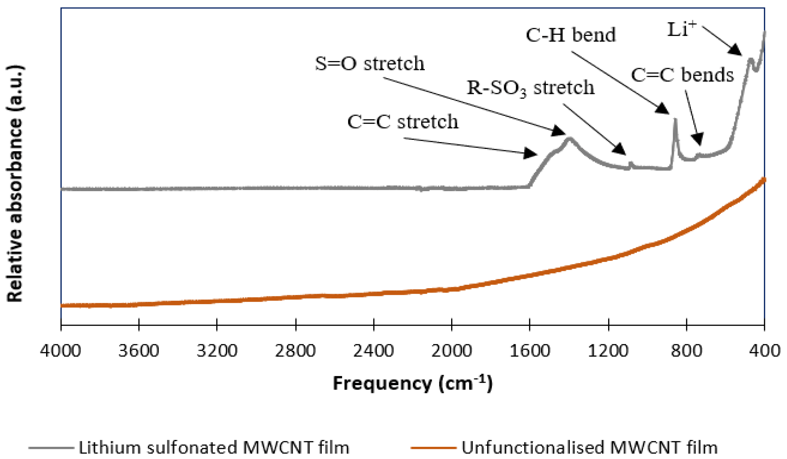
3.5. Infrared (IR) Spectroscopy

The two MWCNT film types show different infrared spectra (Figure 6), due to surface functionalisation of the carbon that is fully consistent with the XPS data. The unfunctionalised film shows little-to-no surface functionality (no distinct sharp and/or broad peaks) in the range 4000–400 cm−1. However, following lithium phenylsulfonate functionalisation, several peaks appear at frequencies <1600 cm−1.
Narrow peaks are present at 464, 700, 854 and 1057 cm−1, and broad peaks between 1200–1600 cm−1, with maxima at 1362 and 1450 cm−1. The sharp narrow peaks are assigned to vibration modes involving coordinated Li+ (464 cm−1), C=C and C-H bending (700 and 854 cm−1, respectively) of a para-substituted phenyl ring. The broad peak at 1600–1400 cm−1 (maximum at 1450 cm−1) is assigned as para-substituted phenyl ring C=C stretching. The two remaining peaks are assigned to vibrations shared by sulfonate groups at 1057 (SO3) and 1362 cm−1 (S=O) [42]; those groups are assigned to sulfonate rather than sulfonic acid groups, as there is no broad peak about 3300 cm−1 that would correspond to an O-H stretch. This implies total conversion of the arylsulfonic acid groups to arylsulfonate groups through washing with lithium hydroxide; sulfonates also have subtle spectroscopic differences when compared to sulfonic acids; the SO3 mode of a sulfonic acid group occurs at a lower frequency, approximately 1033 cm−1 [42,43].

3.6. Raman Spectroscopy

The Raman spectra (Figure S3) show a very similar, unremarkable carbon spectrum for both non-functionalised and functionalised films. The two significant peaks in both spectra occur at 1343 and 1576 cm−1, corresponding to the D-band and the G-band of the carbon nanotubes, respectively. The ID/IG ratio (being a measure of disorder/order) was found to vary by 0.09 (1.29 for the unfunctionalised and 1.20 for the lithium phenylsulfonated MWCNT films).
A carbon D’-band is also observed at 1615 cm−1 for both film types and is commonly seen for MWCNTs [44,45]. There are also two lower energy peaks present, at 2692 and 2957 cm−1, which are the 2D and (D + G) combination-bands respectively. The only difference between the spectra of MWCNTs before and after phenylsulfonation is the addition of low-intensity peaks close to the baseline around the D- and G-bands for the sulfonated film. The peak at 1100–1200 cm−1 was assigned to a complex vibration ν(C, S, SO3) due to functionalisation [46]. The peak at 1420–1520 cm−1 is consistent with an added phenyl ring which introduces aromatic ν(C-C) [46].

3.7. Elemental Microanalysis

The CHNS results in Table 4 show that both films were >85%mass carbon (irrespective of functionalisation). Once functionalised, the carbon content reduced by 0.52%mass C. The nitrogen and sulfur contents rose after functionalisation as a direct consequence of the addition route via diazotised functional groups. The sulfur content simultaneously increased by only 0.97%mass S after functionalisation; this is believed to be (i) due to a phenyl ring being added during the addition of the sulfonate group (44%mass of the added lithium phenylsulfonate moieties is carbon) and (ii) due to light decoration of MWCNTs with those sulfonate groups; CHNS microananalysis is a gravimetric average of the surface and subsurface/bulk of the sample. In comparison, the XPS elemental surface concentrations (shown in Table 3) show a large 12.1%atom O surface concentration before lithium phenylsulfonate functionalisation of the MWCNTs (due to surface impurities), which reduced to 5.5%atom O after functionalisation.

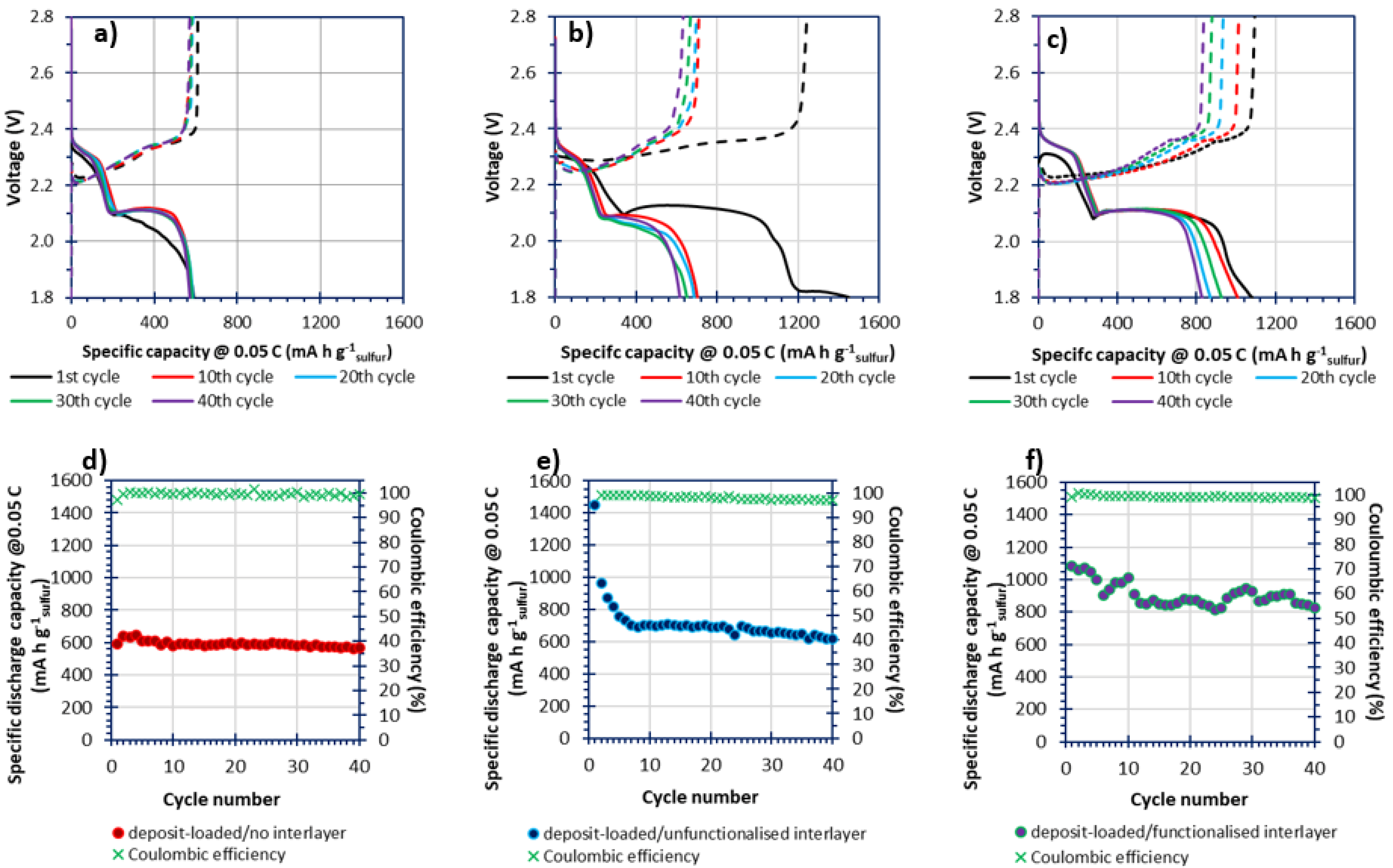
3.8. In-Cell Electrochemical Investigations via GDC Cycling

The low E/S of 10 μL mg−1sulfur did not factor in an interlayer’s addition, which, therefore, precluded the fast cycling at C-rates of 1–2 C due to accelerated electrolyte depletion at higher discharge/charge rates [47]. Therefore, slow cycling at 0.05 C was used as the testing C-rate.
Figure 7 shows the GDC cycling data of three differing cells of the same cathode composition (where the sulfur has been deposited on, as opposed to melted in, the resole-type carbon via thiosulfate acidification [i.e., the composites are deposit-loaded]) but with the presence of (and if present, types of) carbon interlayers [26]. Figure 7a,d shows cycling of a cell over 40 cycles at 0.05 C for a cell without a carbonaceous interlayer. The cell showed great cycling stability but only displayed a specific capacity of ca. 600 mA h g−1sulfur (the theoretical specific capacity of an LSB being 1675 mA h g−1sulfur). When studying the discharge–charge profile of that cell (Figure 7a), the poor performance was due to poor recovery of the lower discharge plateau (~2.10 V) associated with lower-order polysulfides (low n-value Sn2−) [48].
Figure 7b,e show the cycling performance of a cell assembled including an unfunctionalised MWCNT film (using the same cathode as in Figure 7a); the specific capacities for the first few cycles were greater (1440 mA h g−1sulfur at the first cycle, with a reduction of 474 mA h g−1sulfur by the second cycle) relative to the specific capacities of the cell assembled without an interlayer but decayed to 700 mA h g−1sulfur by the seventh cycle. Moreover, the coulombic efficiency of the first cycle was ~116% (off the scale shown in Figure 7e), supporting the hypothesis that unfunctionalised carbonaceous interlayers facilitate charge transfer yet expedite irreversible losses associated with side reactions. This result was repeatable with similar fresh cells. The cell’s capacity then decayed slowly to 600 mA h g−1sulfur at the fortieth cycle. After 40 cycles, and because of polysulfide shuttling, the cell performed closely and similarly to the cell assembled without the unfunctionalised interlayer. Therefore, adding an unfunctionalised MWCNT interlayer increased the conductive surface (thereby increasing sulfur utilisation), but as the interlayer surface was not optimised, since it was unfunctionalised (and therefore non-polar), it was unable to retain the soluble and polar polysulfide intermediates [10,31].
Figure 7c,f show the performance for a cell including a functionalised MWCNT interlayer, showing an initial specific capacity of 1100 mA h g−1sulfur at 0.05 C (with a reduction of 20 mA h g−1sulfur by the second cycle). The specific capacities varied slightly over 40 cycles, but the specific capacity remained high (800 mA h g−1sulfur at cycle 40). That indicates that the functionalised interlayer improves the performance of the cell, producing a longer lower voltage plateau. However, the lower effective E/S, caused by the necessary wetting for the added interlayers, increased the polarisation voltages experienced by the cells assembled with interlayers, relative to the cells assembled without an interlayer [49]. All cells produced coulombic efficiencies of 98–100% from the second cycle onwards; this suggests that the added lithium nitrate in the electrolyte largely forestalled rapid polysulfide shuttling across the cells by forming a stable solid–electrolyte interface (SEI) on the anode surface [50,51]. However, the greatest extent of polysulfide shuttling was the cell assembled with an unfuctionalised MWCNT interlayer, which also corresponded to the lowest coulombic efficiencies that were displayed. What appears to be clear is that the interlayers initially improve the sulfur utilisation and polysulfide conversion kinetics within the LSBs. However, the rapidness of the capacity loss that eventually ensues can be delayed and limited in the initial cycles by adding functionality. The capacity reduction within the first 10 cycles were shown to be ~ 740 mA h g−1sulfur for a cell with an unfunctionalised interlayer and 160 mA h g−1sulfur for a cell with a lithium phenylsulfonated interlayer.
Figure S4a,b show a cell with a cathode of melt-loaded sulfur on Reg-600 carbon and assembled with a functionalised MWCNT interlayer (to compare against the behaviour observed in Figure 7c,f with deposition-loaded sulfur composite on the cathode). The melt-loaded cathode led to a greatly increased initial specific capacity of ca. 1000 mA h g−1sulfur at 0.05 C, which slowly decayed to 600 mA h g−1sulfur; from the previous work featuring melt-loaded Reg-600, specific capacities were stable over the same cycling regime at 600 mA h g−1sulfur when assembled without an interlayer [26]. Thus, as sulfur-loadings were consistent between both works (being this work and the cited work), the deposit-loaded cell proved to have better capacity recovery, when an interlayer was used, over the same testing regime (relative to the melt-loaded cell).
The results show that, after only 40 cycles, the cell with the unfunctionalised interlayer performed as well as the cell without any interlayer. Furthermore, the cell with the functionalised interlayer was still ~200 mA h g−1sulfur greater than either of the other cell results at the same C-rate.
The rationale given for the improved upper and lower voltage plateaus (2.30 and 2.10 V, respectively) suggests that the lithium sulfonated interlayer’s sulfonate group centres promote, and sustain, favourable conversions for both the higher- (Sn2−, S82− to S42−) and lower-order polysulfides (Sn2−, S42− to S22−). Mechanistically, this was thought to be caused by the intermediate polysulfides reacting with the sulfonate group centres, producing oxygenated-polysulfide species [52]. Literature sources have suggested that this effect might be consistent with the formation of intermediate side-products such as dithionite, thiosulfate and polythionate species [53,54].
Mirroring that of the previous study that featured the cells of Reg-600, the observed charge storage capacities were less than the theoretical maximum of 1675 mA h g−1sulfur [26]. The reasons for the lower-than-theoretical charge storage abilities of those cathodes was attributed to (i) high-sulfur-content cathodes (a cathode coating of 70%mass sulfur), (ii) the low content of sulfur-host (10%mass) and (iii) the use of such a restrictive 10 µL mg−1sulfur E/S ratio for batteries [26]. Yet, the E/S was unchanged from the previous study (10 µL mg−1sulfur) irrespective of an interlayer’s addition in the coin cell [i.e., cells assembled with an interlayer received no more electrolyte relative to the previous study]. Thus, the E/S of 10 µL mg−1sulfur was only based on the cathode; the requirement to wet an added interlayer means that the true/effective E/S was more restrictive.
With reference to Figure 8, the proposed mechanisms of the carbonaceous MWCNT interlayers used in this research are three-fold. Firstly, the added conductivity (that is largely neglected at the cathode surface/farthest from the electrode’s current collector) greatly improves the charge-transfer mediation needed for sulfur/polysulfide/disulfide/sulfide species at the cathode surface [55]. Secondly, the lithium phenylsulfonate groups that adorn the MWCNT surfaces (if functionalised) act as a charged screen that largely blocks repulsively charged negative, but soluble, polysulfide species during cycling [31]. Finally, the sulfonate centres interacted with the polysulfide species, forming oxygenated polysulfide species which can immobilise other remaining polysulfide species [56,57].

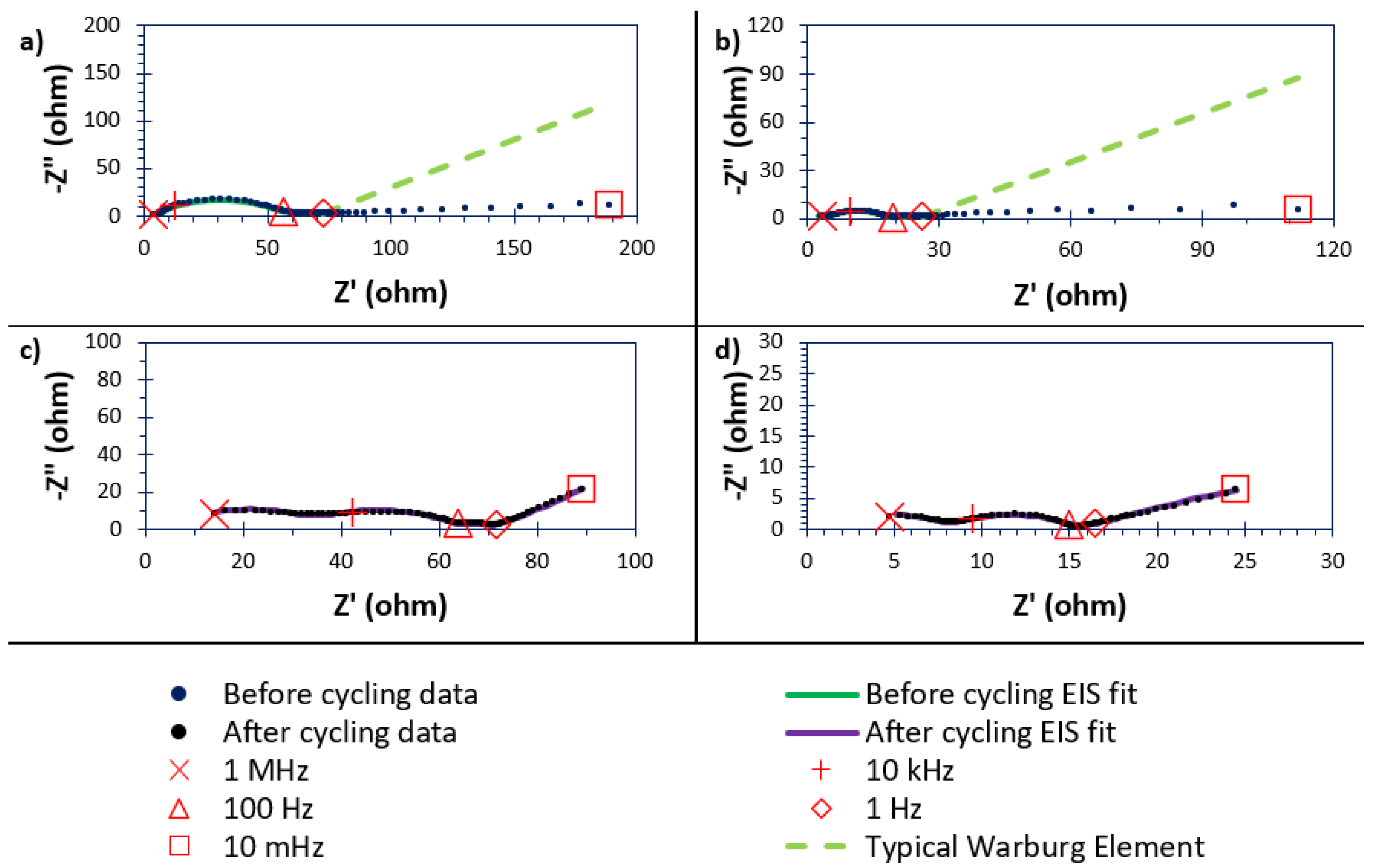
3.9. In-Cell Studies Using Electrochemical Impedance Spectroscopy (EIS)

Figure 9 shows EIS data recorded for cells before and after GDC cycling and presents that data in the form of Nyquist plots. The cell in Figure 9a has an unfunctionalised MWCNT interlayer, while the cell in Figure 9b differs by using a functionalised interlayer. Changing to the functionalised interlayer leads to significant changes in the impedance spectra, both before and after GDC cycling.
At the lowest frequencies (10 Hz and lower), lithium-ion diffusion within porous structures typically leads to analysis in terms of a Warburg element (at approximately 45° from the Z′/real impedance axis) in the Nyquist plot. Before cycling, the cells in this study produce low-frequency slopes at ca. 10° and which cannot be fitted as a Warburg element. Moreover, this effect of a heavily “compressed” charge-transfer semicircle occurred for both cells that were assembled with an interlayer; this suggests that the effect is independent of interlayer fuctionalisation and is instead a function of cell architecture and assembly. This effect was thought to be caused by a combination of (i) the interlayers’ increased surface areas required to wet, as well as the cathode, under lean electrolyte conditions (E/S >> 10 µL mg−1sulfur), and (ii) the increased electrolyte viscosity of the polysulfide species caused by an increase in sulfur utilisation because of the interlayers’ added conductivities [58,59]. All of the described reasons could lead to a reduction of ionic and particle diffusion, caused by heterogenous cathode/interlayer make-ups, manifesting as a collapse of the charge-transfer capacitance behaviour.
Similar effects have been observed when studying solid-state (SS) lithium-cobalt-oxide-type LIBs (LCO cells) using the SS electrolyte Li10GeP2S12 (LGPS); the associated paper describes a synthesis procedure for modification of the anode surface [60]. For the LGPS cell, the low-frequency behaviour is attributed to deterioration of the electrolyte–anode interface (of an unfunctionalised anode) and associated lowering of lithium-ion migration to the anode surface [60]. In relation to liquid electrolyte cells with interlayers from this study, the interlayer before cycling behaves like a sponge for electrolytes (as the E/S remained at a constant 10 µL mg−1sulfur [only relative to the cathode]) and therefore struggles to properly wet the electrode surfaces prior to cycling. Once current is applied (on cycling), the electrolyte wets the electrode surfaces in a suitable manner, to result in a Warburg-like element. In the current study, wetting is improved by cycling. Furthermore, after polysulfide shuttling, as shown by the reduction in cycling performances, fewer polysulfides are present at the cathode/interlayer, and this would reduce the electrolyte viscosity. This is supported by the formation of an SEI and increased series resistance once cycled [59,61].
Before cycling, the spectrum for the uncycled cell with an unfunctionalised interlayer produces two arcs/semicircles (Figure 9a, black data), the larger of which is asymmetrical, implying overlap of a model equivalent circuit with more than one RC pair. Before cycling, the behaviour can be described by three RC pairs that are attributed to (i) a positive bulk contribution of the carbon cathode, (ii) charge transfer of the polysulfide species and (iii) the presence of a Li2S/Li2S2 film on the electrode surfaces (in order of increasing capacitance). The low-frequency data points were attributed to the electrolyte’s problematic transfer of charge to and from the electrode surfaces [60]. After cycling, the in-cell resistance decreases, and the detectable processes were SEI formation (left-hand semicircle), charge transfer by the polysulfide species (right-hand semicircle), and the presence of a Li2S/Li2S2 film (in order of increasing capacitance), as well as typical Warburg-like diffusion of the lithium ions into the pores of the cathode. The spectra shown in Figure 9a,b show the complete EIS data between 1 MHz and 10 MHz. However, this has also given the unfortunate effect of compressing the display of the higher-frequency electronic data (1 MHz to 10 Hz). Therefore, for completeness and clarity, a restriction of the higher frequencies for Figure 9a,b is shown in Figure S5.
The impedance spectrum of the cell assembled using the functionalised (lithium phenylsulfonated) interlayer is also two arcs/semicircles, the larger of which is again asymmetrical, implying overlap of more than one RC pair, and was described by three RC pairs, but with smaller resistances than with the unfunctionalised interlayer; the processes were again consistent with a positive bulk contribution of the carbon cathode, charge transfer of the polysulfide species, and the presence of a Li2S/Li2S2 film (in order of increasing capacitance). As with the functionalised interlayer, the low-frequency points that were not fitted were attributed to issues with wetting the anode surface [60]. After cycling, the cell resistance again decreases, and the processes detected are SEI formation, charge transfer of the polysulfide species and diffusional impedance (in order of increasing capacitance). No presence of a Li2S/Li2S2 film was detected, and this could suggest a catalytic effect from the phenylsulfonate groups from the interlayer redistributing the sulfur more optimally [61,62]. Figure S6 and Table S1 describe the equivalent circuits and the fitted component values, respectively.

4. Conclusions

Adding interlayer films of MWCNTs improves utilisation of the sulfur active material, as shown by providing larger specific capacities. One factor driving this effect is the improved conductivity across the surface of the cathode coating. However, if the MWCNT film interlayer is unfunctionalized, this enhanced initial performance quickly dies away during cycling; that rapid fade is indicative of polysulfide shuttling which also seems enhanced relative to not adding an interlayer to the LSB. In contrast, when a functionalised interlayer is used, the cycle lifetime of the cell improves. These effects are not mutually exclusive, as functionalisation will convert some sp2 carbons (associated with MWCNT electronic conductivity) to sp3 carbons, thereby lowering the electronic conductivity of the fabricated film as polysulfide-shuttle-suppressing functional groups are added. However, the results clearly indicate the necessity of these functional groups to reduce polysulfide shuttling. XPS, SEM-EDX and FTIR results demonstrate surface functionalisation with grafted phenylsulfonate functionalities and consequent colocation of sulfur and oxygen at the atomic level. CHNS and powder XRD results indicate a low level of surface functionalisation of MWCNTs with no observable difference in the crystallinity relative to unfunctionalised MWCNTs.
The limited performance displayed by the cells, leading to the limited storage capacities, was because a commercially relevant (if less than ideal) and restrictive 10 µL mg−1sulfur E/S ratio (based solely on the cathode) was used. All LSB cells that were tested in this paper are demonstrable proofs of concept that further the scientific discussion for the beneficial use of polar/functionalised carbonaceous interlayers and their abilities to act as secondary current collectors for the cathodes of LSBs.

Supplementary Materials

The following supporting information can be downloaded at: https://www.mdpi.com/article/10.3390/batteries11070266/s1, Figure S1: The pore size distributions (left) and cumulative pore volumes (right) of the unfunctionalised and lithium sulfonated MWCNT films, calculated using the respective nitrogen sorption isotherms present in Figure 3 and computed using a non-localised density functional theory model within the 3Flex MicroActive (Micromeritics®) software package; Figure S2: Peak fittings of the C 1s XPS peaks given in Figure 5: (a) unfunctionalised MWCNT film and (b) lithium sulfonated MWCNT films; Figure S3: Raman spectra of the unfunctionalised and lithium sulfonated MWCNT films; Figure S4: (a) The 10-cycle interval discharge and charge profiles for a melt-loaded Reg-600 cell assembled without an interlayer film, as well as (b) the progression over 40 cycles at 0.05 C; Figure S5: EIS spectra for cells before cycling, showing data points and the output from fitted equivalent circuit restricted to the higher frequency datapoints (caused by electronic effects) as previously displayed in Figure 9. The cells in Figure 9a have the unfunctionalised MWCNT interlayer, whereas the cells in Figure 9b have the lithium sulfonated MWCNT interlayer. Blue data points were obtained before cycling. The green line series shows the EIS fitted model before cycling. The red data points display the frequency of each measured data point every 2 decades. The lime dashed line indicates a typical Warburg element that would be expected by the resistance increase observed; Figure S6: The equivalent circuit diagrams of the two cells under study by EIS: (a) and (c) deposit-loaded cell assembled with an unfunctionalised MWCNT interlayer film, and (b) and (d) deposit-loaded cell assembled with lithium sulfonated MWCNT interlayer film. The equivalent circuits of the cells before cycling are given as (a) and (c), and the equivalent circuits of the cells after cycling are given as (b) and (d); Table S1: Values for the constructed equivalent circuit models used to fit to the impedance data of deposit-loaded cells assembled with either lithium sulfonated or unfunctionalised MWCNT film (taken after 2+ h at OCV before and after cycling).

Author Contributions

Conceptualisation, R.C.T.S. and C.C.; methodology, L.D.J.B. and C.C.; investigation, L.D.J.B. and S.J.H.; writing, original draft preparation, L.D.J.B.; writing, review, and editing, R.C.T.S., J.F.W. and C.C.; XPS assignment review, S.J.H. and J.F.W.; Project administration, R.C.T.S. and C.C. All authors have read and agreed to the published version of the manuscript.

Funding

This research was funded by The Faraday Institution grant number FIRG014 (LiSTAR project). The Article Processing Charges (APCs) were funded under the Institutional Open Access Program (IOAP) through the University of Surrey and MDPI.

Data Availability Statement

Data for this paper are available at the University of Surrey Open Research repository at https://doi.org/10.15126/thesis.901070. The data pertinent to this research is, however, currently under Embargo Status (until 1 May 2026) and so are not available at the time of submission for confidentiality reasons.

Acknowledgments

We thank EPSRC for a strategic equipment grant for Raman microscopy (EP/M022749/1). We thank Medac Ltd. for CHNS analyses and the University of Surrey for access to the electron microscopes at its central MicroStructural Studies Unit (MSSU). The authors have reviewed and edited the output and take full responsibility for the content of this publication.

Conflicts of Interest

The authors declare no conflicts of interest. The funders had no role in the design of the study; in the collection, analyses, or interpretation of data; in the writing of the manuscript; or in the decision to publish the results.

Abbreviations

The following abbreviations are used in this manuscript:
MWCNTmultiwalled carbon nanotubes
LSBLithium–sulfur battery
LIBLithium-ion battery
SB0Bridging sulfur
ST1−Polysulfide termini
CNTCarbon nanotubes
E/SElectrolyte-to-sulfur
ACSAmerican chemical society
CTABCetyltrimethyl ammonium bromide
NMPN-methyl 2-pyrolidone
PVDFPolyvinylidene difluoride
MWMolecular weight
GPCGel permeation chromatography
DME1,2-Dimethoxyethane
DOL1,3-Dioxolane
BHTButylated hydroxytoluene
LiTFSILithium bis(trifluromethanesulfonyl)imide
HEPAHigh-efficiency particulate air
XRDX-ray diffraction
XPSX-ray photoelectron spectroscopy
IRInfrared
UATRUniversal attenuated total reflectance
FTFourier transform
SEMScanning electron microscopy
EDXEnergy-dispersive X-ray
CHNSCarbon, hydrogen, nitrogen and sulfur
DFCDynamic flash combustion
TDCThermal conductivity detector
GDCGalvanic discharge–charge
EISElectrochemical impedance spectroscopy
OCVOpen-circuit voltage
SEISolid–electrolyte interface
BetBrunauer–Emmett–Teller
LCOLithium cobalt oxide
LGPSLi10GeP2S12

References

  1. Zhu, J.; Zou, J.; Cheng, H.; Gu, Y.; Lu, Z. High Energy Batteries Based on Sulfur Cathode. Green Energy Environ. 2019, 4, 345–359. [Google Scholar] [CrossRef]
  2. Shi, C.; Takeuchi, S.; Alexander, G.V.; Hamann, T.; O’Neill, J.; Dura, J.A.; Wachsman, E.D. High Sulfur Loading and Capacity Retention in Bilayer Garnet Sulfurized-Polyacrylonitrile/Lithium-Metal Batteries with Gel Polymer Electrolytes. Adv. Energy Mater. 2023, 13, 2301656. [Google Scholar] [CrossRef]
  3. Nakamura, N.; Ahn, S.; Momma, T.; Osaka, T. Future Potential for Lithium-Sulfur Batteries. J. Power Sources 2023, 558, 232566. [Google Scholar] [CrossRef]
  4. Danner, T.; Latz, A. On the Influence of Nucleation and Growth of S8 and Li2S in Lithium-Sulfur Batteries. Electrochim. Acta 2019, 322, 134719. [Google Scholar] [CrossRef]
  5. Saedi, S.; Shokri, M.; Rhim, J.-W. Antimicrobial Activity of Sulfur Nanoparticles: Effect of Preparation Methods. Arab. J. Chem. 2020, 13, 6580–6588. [Google Scholar] [CrossRef]
  6. Xiao, R.; Yu, T.; Yang, S.; Chen, K.; Li, Z.; Liu, Z.; Hu, T.; Hu, G.; Li, J.; Cheng, H.M.; et al. Electronic Structure Adjustment of Lithium Sulfide by a Single-Atom Copper Catalyst toward High-Rate Lithium-Sulfur Batteries. Energy Storage Mater. 2022, 51, 890–899. [Google Scholar] [CrossRef]
  7. Feng, Z.; Kim, C.; Vijh, A.; Armand, M.; Bevan, K.H.; Zaghib, K. Unravelling the Role of Li2S2 in Lithium-Sulfur Batteries: A First Principles Study of Its Energetic and Electronic Properties. J. Power Sources 2014, 272, 518–521. [Google Scholar] [CrossRef]
  8. Wang, H.; Zhang, W.; Xu, J.; Guo, Z. Advances in Polar Materials for Lithium–Sulfur Batteries. Adv. Funct. Mater. 2018, 28, 1707520. [Google Scholar] [CrossRef]
  9. Lin, Y.; Huang, S.; Zhong, L.; Wang, S.; Han, D.; Ren, S.; Xiao, M.; Meng, Y. Organic Liquid Electrolytes in Li-S Batteries: Actualities and Perspectives. Energy Storage Mater. 2021, 34, 128–147. [Google Scholar] [CrossRef]
  10. Shutthanandan, V.; Nandasiri, M.; Zheng, J.; Engelhard, M.H.; Xu, W.; Thevuthasan, S.; Murugesan, V. Applications of XPS in the Characterization of Battery Materials. J. Electron Spectros. Relat. Phenom. 2019, 231, 2–10. [Google Scholar] [CrossRef]
  11. Fan, Y.; Niu, Z.; Zhang, F.; Zhang, R.; Zhao, Y.; Lu, G. Suppressing the Shuttle Effect in Lithium-Sulfur Batteries by a UiO-66-Modified Polypropylene Separator. ACS Omega 2019, 4, 10328–10335. [Google Scholar] [CrossRef]
  12. Fan, L.; Li, M.; Li, X.; Xiao, W.; Chen, Z.; Lu, J. Interlayer Material Selection for Lithium-Sulfur Batteries. Joule 2019, 3, 361–386. [Google Scholar] [CrossRef]
  13. Zhang, X.; Bai, X.; Wei, C.; Wang, Z.; Xi, B.; Xiong, S.; Feng, J. Triggering the Electronic Microenvironment of Extraordinary Nitrogen-Bridged Atomic Iron Coordinated with in-Plane Nitrogen by Manipulating Phase-Reconfigured 2D Vanadium Nitride MXenes toward Invigorated Lithium–Sulfur Batteries. Energy Environ. Sci. 2024, 17, 7403–7415. [Google Scholar] [CrossRef]
  14. Lee, B.-J.; Zhao, C.; Yu, J.-H.; Kang, T.-H.; Park, H.-Y.; Kang, J.; Jung, Y.; Liu, X.; Li, T.; Xu, W.; et al. Development of High-Energy Non-Aqueous Lithium-Sulfur Batteries via Redox-Active Interlayer Strategy. Nat. Commun. 2022, 13, 4629. [Google Scholar] [CrossRef] [PubMed]
  15. Kim, J.H.; Ko, Y.i.; Kim, Y.A.; Kim, K.S.; Yang, C.M. Sulfur-Doped Carbon Nanotubes as a Conducting Agent in Supercapacitor Electrodes. J. Alloys Compd. 2021, 855, 157282. [Google Scholar] [CrossRef]
  16. Salice, P.; Fabris, E.; Sartorio, C.; Fenaroli, D.; Figà, V.; Casaletto, M.P.; Cataldo, S.; Pignataro, B.; Menna, E. An Insight into the Functionalisation of Carbon Nanotubes by Diazonium Chemistry: Towards a Controlled Decoration. Carbon 2014, 74, 73–82. [Google Scholar] [CrossRef]
  17. Fretz, S.J.; Pal, U.; Girard, G.M.A.; Howlett, P.C.; Palmqvist, A.E.C. Lithium Sulfonate Functionalization of Carbon Cathodes as a Substitute for Lithium Nitrate in the Electrolyte of Lithium–Sulfur Batteries. Adv. Funct. Mater. 2020, 30, 2002485. [Google Scholar] [CrossRef]
  18. Guthrie, J.P. Hydrolysis of Esters of Oxy Acids: PKa Values for Strong Acids; Brønsted Relationship for Attack of Water at Methyl; Free Energies of Hydrolysis of Esters of Oxy Acids; and a Linear Relationship between Free Energy of Hydrolysis and PKa Holding over a Ran. Can. J. Chem. 1978, 56, 2342–2354. [Google Scholar] [CrossRef]
  19. Ma, L.; Zhuang, H.L.; Wei, S.; Hendrickson, K.E.; Kim, M.S.; Cohn, G.; Hennig, R.G.; Archer, L.A. Enhanced Li-S Batteries Using Amine-Functionalized Carbon Nanotubes in the Cathode. ACS Nano 2016, 10, 1050–1059. [Google Scholar] [CrossRef]
  20. Park, S.K.; Lee, J.K.; Kang, Y.C. Yolk–Shell Structured Assembly of Bamboo-Like Nitrogen-Doped Carbon Nanotubes Embedded with Co Nanocrystals and Their Application as Cathode Material for Li–S Batteries. Adv. Funct. Mater. 2018, 28, 1705264. [Google Scholar] [CrossRef]
  21. Gaikwad, M.M.; Sarode, K.K.; Pathak, A.D.; Sharma, C.S. Ultrahigh Rate and High-Performance Lithium-Sulfur Batteries with Resorcinol-Formaldehyde Xerogel Derived Highly Porous Carbon Matrix as Sulfur Cathode Host. Chem. Eng. J. 2021, 425, 131521. [Google Scholar] [CrossRef]
  22. Kim, P.J.H.; Kim, K.; Pol, V.G. Towards Highly Stable Lithium Sulfur Batteries: Surface Functionalization of Carbon Nanotube Scaffold. Carbon 2018, 131, 175–183. [Google Scholar] [CrossRef]
  23. Lu, Y.; Gu, S.; Guo, J.; Rui, K.; Chen, C.; Zhang, S.; Jin, J.; Yang, J.; Wen, Z. Sulfonic Groups Originated Dual-Functional Interlayer for High Performance Lithium-Sulfur Battery. ACS Appl. Mater. Interfaces 2017, 9, 14878–14888. [Google Scholar] [CrossRef] [PubMed]
  24. Lee, J.H.; Kang, J.; Kim, S.W.; Halim, W.; Frey, M.W.; Joo, Y.L. Effective Suppression of the Polysulfide Shuttle Effect in Lithium-Sulfur Batteries by Implementing RGO-PEDOT:PSS-Coated Separators via Air-Controlled Electrospray. ACS Omega 2018, 3, 16465–16471. [Google Scholar] [CrossRef]
  25. Chang, C.H.; Chung, S.H.; Manthiram, A. Ultra-Lightweight PANiNF/MWCNT-Functionalized Separators with Synergistic Suppression of Polysulfide Migration for Li-S Batteries with Pure Sulfur Cathodes. J. Mater. Chem. A 2015, 3, 18829–18834. [Google Scholar] [CrossRef]
  26. Barter, L.D.J.; Mohammad, I.; Hinder, S.J.; Watts, J.F.; Slade, R.C.T.; Crean, C. Carbons Derived from Resole-Type Phenolic Resins for Use in Lithium–Sulfur Batteries: Templating the Resins with Sulfur Leads to Enhanced Cell Performance. Energy Adv. 2024, 3, 471–481. [Google Scholar] [CrossRef]
  27. Renda, C.G.; Bertholdo, R. Study of Phenolic Resin and Their Tendency for Carbon Graphitization. J. Polym. Res. 2018, 25, 241. [Google Scholar] [CrossRef]
  28. Ungár, T. Microstructural Parameters from X-Ray Diffraction Peak Broadening. Scr. Mater. 2004, 51, 777–781. [Google Scholar] [CrossRef]
  29. Sirivisoot, S.; Webster, T.J. 3.32 Carbon Nanotubes: Applications for In Situ Implant Sensors. In Comprehensive Biomaterials II; Ducheyne, P., Ed.; Elsevier: Oxford, UK, 2017; pp. 703–715. ISBN 978-0-08-100692-4. [Google Scholar]
  30. Azman, N.H.N.; Sulaiman, Y. Hierarchical Porous Materials for Supercapacitors. In Encyclopedia of Energy Storage; Cabeza, L.F., Ed.; Elsevier: Oxford, UK, 2022; pp. 622–637. ISBN 978-0-12-819730-1. [Google Scholar]
  31. Hippauf, F.; Nickel, W.; Hao, G.P.; Schwedtmann, K.; Giebeler, L.; Oswald, S.; Borchardt, L.; Doerfler, S.; Weigand, J.J.; Kaskel, S. The Importance of Pore Size and Surface Polarity for Polysulfide Adsorption in Lithium Sulfur Batteries. Adv. Mater. Interfaces 2016, 3, 1600508. [Google Scholar] [CrossRef]
  32. Chen, X.; Gross, A.J.; Giroud, F.; Holzinger, M.; Cosnier, S. Comparison of Commercial and Lab-Made MWCNT Buckypaper: Physicochemical Properties and Bioelectrocatalytic O2 Reduction. Electroanalysis 2018, 30, 1511–1520. [Google Scholar] [CrossRef]
  33. Khan, Z.U.; Kausar, A.; Ullah, H. A Review on Composite Papers of Graphene Oxide, Carbon Nanotube, Polymer/GO, and Polymer/CNT: Processing Strategies, Properties, and Relevance. Polym. Plast. Technol. Eng. 2016, 55, 559–581. [Google Scholar] [CrossRef]
  34. Ensling, D.; Stjerndahl, M.; Nytén, A.; Gustafsson, T.; Thomas, J.O. A Comparative XPS Surface Study of Li2FeSiO4/C Cycled with LiTFSI- and LiPF6-Based Electrolytes. J. Mater. Chem. 2009, 19, 82–88. [Google Scholar] [CrossRef]
  35. Liu, L.; Chen, X.; Wang, Z.; Wang, X.; Lin, S. The Removal Mechanism and Performance of Tetrabromobisphenol A with a Novel Multi-Group Activated Carbon from Recycling Long-Root: Eichhornia Crassipes Plants. RSC Adv. 2019, 9, 24760–24769. [Google Scholar] [CrossRef] [PubMed]
  36. Jia, R.; Chen, J.; Zhao, J.; Zheng, J.; Song, C.; Li, L.; Zhu, Z. Synthesis of Highly Nitrogen-Doped Hollow Carbon Nanoparticles and Their Excellent Electrocatalytic Properties in Dye-Sensitized Solar Cells. J. Mater. Chem. 2010, 20, 10829–10834. [Google Scholar] [CrossRef]
  37. Lee, M.-T.; Liu, H.; Brandell, D. The Surface Chemistry of Thin Lithium Metal Electrodes in Lithium-Sulfur Cells. Batter. Supercaps 2020, 3, 1370–1376. [Google Scholar] [CrossRef]
  38. Shanthi, P.M.; Hanumantha, P.J.; Ramalinga, K.; Gattu, B.; Datta, M.K.; Kumta, P.N. Sulfonic Acid Based Complex Framework Materials (CFM): Nanostructured Polysulfide Immobilization Systems for Rechargeable Lithium–Sulfur Battery. J. Electrochem. Soc. 2019, 166, A1827–A1835. [Google Scholar] [CrossRef]
  39. Rojas, J.V.; Toro-Gonzalez, M.; Molina-Higgins, M.C.; Castano, C.E. Facile Radiolytic Synthesis of Ruthenium Nanoparticles on Graphene Oxide and Carbon Nanotubes. Mater. Sci. Eng. B 2016, 205, 28–35. [Google Scholar] [CrossRef]
  40. Koushik, D.; Verhees, W.J.H.; Zhang, D.; Kuang, Y.; Veenstra, S.; Creatore, M.; Schropp, R.E.I. Atomic Layer Deposition Enabled Perovskite/PEDOT Solar Cells in a Regular n–i–p Architectural Design. Adv. Mater. Interfaces 2017, 4, 1700043. [Google Scholar] [CrossRef]
  41. Dubina, E.; Plank, J.; Black, L. Impact of Water Vapour and Carbon Dioxide on Surface Composition of C3A Polymorphs Studied by X-Ray Photoelectron Spectroscopy. Cem. Concr. Res. 2015, 73, 36–41. [Google Scholar] [CrossRef]
  42. Parker, S.F.; Revill-Hivet, E.J.; Nye, D.W.; Gutmann, M.J. Structure and Vibrational Spectroscopy of Lithium and Potassium Methanesulfonates. R. Soc. Open Sci. 2020, 7, 200776. [Google Scholar] [CrossRef]
  43. Jiang, K.; Gao, S.; Wang, R.; Jiang, M.; Han, J.; Gu, T.; Liu, M.; Cheng, S.; Wang, K. Lithium Sulfonate/Carboxylate-Anchored Polyvinyl Alcohol Separators for Lithium Sulfur Batteries. ACS Appl. Mater. Interfaces 2018, 10, 18310–18315. [Google Scholar] [CrossRef]
  44. Childres, I.; Jauregui, L.A.; Park, W.; Caoa, H.; Chena, Y.P. Raman Spectroscopy of Graphene and Related Materials. In New Developments in Photon and Materials Research; Jang, J.I., Ed.; Nova Science Publishers, Inc.: Hauppauge, NY, USA, 2013; pp. 403–418. ISBN 9781626183391. [Google Scholar]
  45. Mohan, S.; Oluwafemi, O.S.; Songca, S.P.; Rouxel, D.; Miska, P.; Lewu, F.B.; Kalarikkal, N.; Thomas, S. Completely Green Synthesis of Silver Nanoparticle Decorated MWCNT and Its Antibacterial and Catalytic Properties. Pure Appl. Chem. 2016, 88, 71–81. [Google Scholar] [CrossRef]
  46. Alía, J.M.; Edwards, H.G.M.; Kiernan, B.M. Raman Spectroscopy of Benzenesulfonic and 4-Toluenesulfonic Acids Dissolved in Dimethylsulfoxide. Spectrochim. Acta Part A Mol. Biomol. Spectrosc. 2004, 60, 1533–1542. [Google Scholar] [CrossRef] [PubMed]
  47. Zerrin, T.; Shang, R.; Dong, B.; Aguilar, E.C.; Malvin, J.; Ozkan, M.; Ozkan, C.S. An Overlooked Parameter in Li-S Batteries: The Impact of Electrolyte-to-Sulfur Ratio on Capacity Fading. Nano Energy 2022, 104, 107913. [Google Scholar] [CrossRef]
  48. Wang, M.; Xia, X.; Zhong, Y.; Wu, J.; Xu, R.; Yao, Z.; Wang, D.; Tang, W.; Wang, X.; Tu, J. Porous Carbon Hosts for Lithium–Sulfur Batteries. Chem. A Eur. J. 2019, 25, 3710–3725. [Google Scholar] [CrossRef] [PubMed]
  49. Zhao, M.; Li, B.-Q.; Zhang, X.-Q.; Huang, J.-Q.; Zhang, Q. A Perspective toward Practical Lithium–Sulfur Batteries. ACS Cent. Sci. 2020, 6, 1095–1104. [Google Scholar] [CrossRef]
  50. Yang, X.; Li, X.; Adair, K.R.; Zhang, H.; Sun, X. Structural Design of Lithium–Sulfur Batteries: From Fundamental Research to Practical Application. Electrochem. Energy Rev. 2018, 1, 239–293. [Google Scholar] [CrossRef]
  51. Jozwiuk, A.; Berkes, B.B.; Weiß, T.; Sommer, H.; Janek, J.; Brezesinski, T. The Critical Role of Lithium Nitrate in the Gas Evolution of Lithium-Sulfur Batteries. Energy Environ. Sci. 2016, 9, 2603–2608. [Google Scholar] [CrossRef]
  52. Blanchard, D.; Slagter, M. In Operando Raman and Optical Study of Lithium Polysulfides Dissolution in Lithium–Sulfur Cells with Carrageenan Binder. J. Phys. Energy 2021, 3, 044003. [Google Scholar] [CrossRef]
  53. Bondy, A.L.; Craig, R.L.; Zhang, Z.; Gold, A.; Surratt, J.D.; Ault, A.P. Isoprene-Derived Organosulfates: Vibrational Mode Analysis by Raman Spectroscopy, Acidity-Dependent Spectral Modes, and Observation in Individual Atmospheric Particles. J. Phys. Chem. A 2018, 122, 303–315. [Google Scholar] [CrossRef]
  54. Xu, L.; Csekő, G.; Petz, A.; Horváth, A.K. Kinetics and Mechanism of the Oxidation of Pentathionate Ion by Chlorine Dioxide in a Slightly Acidic Medium. J. Phys. Chem. A 2014, 118, 1293–1299. [Google Scholar] [CrossRef]
  55. Borah, R.; Hughson, F.R.; Johnston, J.; Nann, T. On Battery Materials and Methods. Mater. Today Adv. 2020, 6, 100046. [Google Scholar] [CrossRef]
  56. Li, J.; Dai, L.; Wang, Z.; Wang, H.; Xie, L.; Chen, J.; Yan, C.; Yuan, H.; Wang, H.; Chen, C. Cellulose Nanofiber Separator for Suppressing Shuttle Effect and Li Dendrite Formation in Lithium-Sulfur Batteries. J. Energy Chem. 2022, 67, 736–744. [Google Scholar] [CrossRef]
  57. Zhe, R.; Zhu, T.; Wei, X.; Ren, Y.; Qing, C.; Li, N.; Wang, H.E. Graphene Oxide Wrapped Hollow Mesoporous Carbon Spheres as a Dynamically Bipolar Host for Lithium-Sulfur Batteries. J. Mater. Chem. A 2022, 10, 24422–24433. [Google Scholar] [CrossRef]
  58. Pathak, R.; Chen, K.; Gurung, A.; Reza, K.M.; Bahrami, B.; Pokharel, J.; Baniya, A.; He, W.; Wu, F.; Zhou, Y.; et al. Fluorinated Hybrid Solid-Electrolyte-Interphase for Dendrite-Free Lithium Deposition. Nat. Commun. 2020, 11, 93. [Google Scholar] [CrossRef] [PubMed]
  59. Shen, C.; Andrei, P.; Zheng, J.P. Stable Cycling of Lithium-Sulfur Batteries by Optimizing the Cycle Condition. Electrochim. Acta 2019, 326, 134948. [Google Scholar] [CrossRef]
  60. Zhang, Z.; Chen, S.; Yang, J.; Wang, J.; Yao, L.; Yao, X.; Cui, P.; Xu, X. Interface Re-Engineering of Li10GeP2S12 Electrolyte and Lithium Anode for All-Solid-State Lithium Batteries with Ultralong Cycle Life. ACS Appl. Mater. Interfaces 2018, 10, 2556–2565. [Google Scholar] [CrossRef]
  61. Guo, W.; Zhang, W.; Si, Y.; Wang, D.; Fu, Y.; Manthiram, A. Artificial Dual Solid-Electrolyte Interfaces Based on in Situ Organothiol Transformation in Lithium Sulfur Battery. Nat. Commun. 2021, 12, 3031. [Google Scholar] [CrossRef]
  62. Yan, J.; Liu, X.; Li, B. Capacity Fade Analysis of Sulfur Cathodes in Lithium–Sulfur Batteries. Adv. Sci. 2016, 3, 1600101. [Google Scholar] [CrossRef]
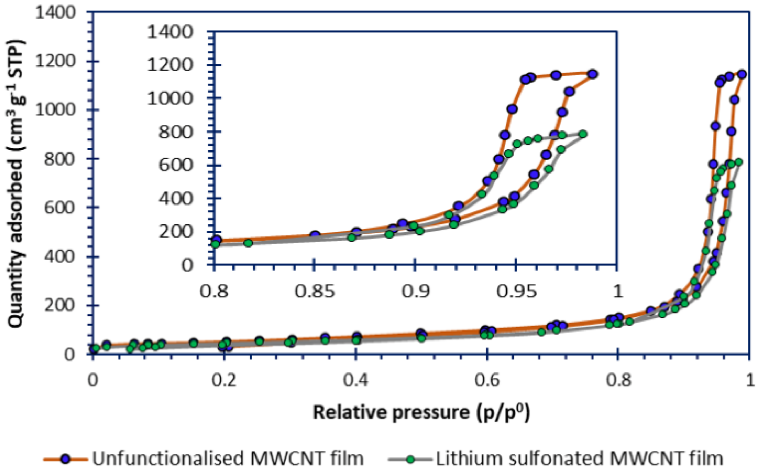
Figure 1. Lithium phenylsulfonation (grafting of the phenylsulfonate moiety) (via diazotisation) of MWCNTs.
Batteries 11 00266 g001
Figure 2. The powder XRD profiles of the MWCNT films. The crystal planes of carbon (shown by the aromatic ring) and hexagonal α-Ti (shown by the asterisk) are overlaid.
Batteries 11 00266 g002
Figure 3. The nitrogen sorption isotherms for the MWCNT film.
Batteries 11 00266 g003
Figure 4. Scanning electron micrographs of the (a) unfunctionalised and (c) lithium sulfonated MWCNT films and their false-coloured EDX elemental maps of the (b) unfunctionalised film and (d) lithium sulfonated films. The false colours correspond to carbon (blue), oxygen (red) and sulfur (yellow).
Batteries 11 00266 g004
Figure 5. The high-resolution XPS spectra of the unfunctionalised and lithium sulfonated MWCNT films of (a) survey spectra, (b) C 1s, (c) N 1s, (d) S 2p, (e) O 1s and (f) Na 1s.
Batteries 11 00266 g005
Figure 6. The FT-ATR-IR absorbance spectra of the unfunctionalised and lithium phenylsulfonate functionalised MWCNT films.
Batteries 11 00266 g006
Figure 7. The 10-cycle interval discharge (solid line) and charge profiles (dash line) for a deposit-loaded cell with (a) no added interlayer, (b) an unfunctionalised MWCNT interlayer and (c) a lithium sulfonated MWCNT interlayer, as well as the relationship over 40 cycles at 0.05 C (e), (d) and (f) [respective for (ac)].
Batteries 11 00266 g007
Figure 8. The proposed differing mechanisms for cells assembled without a carbonaceous MWCNT interlayer, cells assembled with an unfuctionalised carbonaceous MWCNT interlayer, and cells assembled with a lithium sulfonate fuctionalised carbonaceous MWCNT interlayer.
Batteries 11 00266 g008
Figure 9. EIS spectra for cells before and after 40 GDC cycles at 0.05 C, showing data points and the output from fitted equivalent circuit. The cells were made with cathodes coated with deposition-loaded sulfur supported on carbon. The cells in (a,c) are of an unfunctionalised MWCNT interlayer before and after cycling (respectively), whereas the cells in (b,d) are of a lithium sulfonated MWCNT interlayer before and after cycling (respectively). Blue data points were obtained before cycling, and black data points after cycling. The green line series shows the EIS fitted model before cycling and the red line series shows the EIS fitted model after cycling. The red data points display the frequency of each measured data point every 2 decades. The lime dashed line indicates a typical Warburg Element that would be expected by the resistance increase observed.
Batteries 11 00266 g009
Table 2. The specific surface areas of the unfunctionalised MWCNT and lithium phenylsulfonated MWCNT films, which were themselves computed from the respective isotherm data (Figure 3).
SampleSpecific Surface Area # (m2 g−1)
Unfunctionalised MWCNT film197.4 ± 2.2
Functionalised MWCNT film163.2 ± 0.4
# Calculated using the Brunauer–Emmett–Teller (BET) model and computed using the Micromeritics® 3Flex MicroActive (version 5.02) software within the relative pressure (P/P°) range of between 0.05 and 0.35.
Table 3. The elemental surface concentrations of the unfunctionalised and lithium phenylsulfonated MWCNT films as determined through XPS.
SampleC (%atom)N (%atom)S (%atom)O (%atom)Na (%atom)
Unfunctionalised MWCNT film87.3<LOD0.412.10.1
Fuctionalised MWCNT film92.70.61.15.50.1
Table 4. CHNS analyses of the unfunctionalised and lithium phenylsulfonated MWCNT films.
SampleC (%mass)H (%mass)N (%mass)S (%mass)
Unfunctionalised MWCNT film86.502.01<LOD0.66
Functionalised MWCNT film85.982.100.621.63
Limit of detection = 0.10%mass. Measurement error = ±0.30%mass.
Disclaimer/Publisher’s Note: The statements, opinions and data contained in all publications are solely those of the individual author(s) and contributor(s) and not of MDPI and/or the editor(s). MDPI and/or the editor(s) disclaim responsibility for any injury to people or property resulting from any ideas, methods, instructions or products referred to in the content.

