Article

Enhancing the Cycle Life of Silicon Oxide–Based Lithium-Ion Batteries via a Nonflammable Fluorinated Ester–Based Electrolyte

Department of Chemical Engineering & Applied Chemistry, Chungnam National University, Daejeon 34134, Republic of Korea
*
Author to whom correspondence should be addressed.
Batteries 2025, 11(7), 250; https://doi.org/10.3390/batteries11070250
Submission received: 23 May 2025 / Revised: 17 June 2025 / Accepted: 29 June 2025 / Published: 30 June 2025
(This article belongs to the Collection Feature Papers in Batteries)

Abstract

Silicon oxide–graphite is a promising high-capacity anode material for next-generation lithium-ion batteries (LIBs). However, despite using a small fraction (≤5%) of Si, it suffers from a short cycle life owing to intrinsic swelling and particle pulverization during cycling, making practical application challenging. High-nickel (Ni ≥ 80%) oxide cathodes for high-energy-density LIBs and their operation beyond 4.2 V have been pursued, which requires the anodic stability of the electrolyte. Herein, we report a nonflammable multi-functional fluorinated ester–based liquid electrolyte that stabilizes the interfaces and suppresses the swelling of highly loaded 5 wt% SiO–graphite anode and LiNi0.88Co0.08Mn0.04O2 cathode simultaneously in a 3.5 mAh cm−2 full cell, and improves cycle life and battery safety. Surface characterization results reveal that the interfacial stabilization of both the anode and cathode by a robust and uniform solid electrolyte interphase (SEI) layer, enriched with fluorinated ester-derived inorganics, enables 80% capacity retention of the full cell after 250 cycles, even under aggressive conditions of 4.35 V, 1 C and 45 °C. This new electrolyte formulation presents a new opportunity to advance SiO-based high-energy density LIBs for their long operation and safety.

1. Introduction

The advancement of lithium-ion battery (LIB) technology is critical for achieving the industrial demands of high-energy density and safety for electric vehicles (EVs), e-mobility, aviation, and energy storage systems (ESSs) [1]. As higher cathode capacity contributes to an increase in the energy density in LIBs, the use of high-capacity high-nickel LiNixCoyMnzO2 (NCM; x ≥ 80%) layered cathodes has been pursued. Furthermore, an increase in the capacity of a LIB by charging to a higher voltage than the traditional 4.2 V is considered an additional strategy [2]. Silicon (Si) is a potential high-capacity anode material, due to a ≈10-fold higher theoretical specific capacity compared to graphite and an appropriate operation voltage above 0 V versus Li/Li+, avoiding Li-plating [3,4]. However, it suffers from a short cycle life owing to severe volume changes, resulting in swelling of the Si anode, particle pulverization, and damage to the solid electrolyte interphase (SEI) [3,4,5,6,7,8]. In the limited space of any cell, the swelling of the Si anode pushes the pulverized Si particles to cross over through the pores of the polymeric separator, resulting in a short circuit followed by thermal runaway and fire events [8]. Thus, the swelling phenomenon, the SEI stability, and cycling performance are closely linked to each other [8,9,10]. Although the use of silicon oxide (e.g., SiO) can improve cycle stability compared to Si, the same challenges remain [11,12].
Electrolyte engineering to tune the SEI chemistry is a promising approach to enhance the performance of SiO-based anodes [13,14], in addition to the development of various SiO composite materials, binder chemistry, and the application of MPa-level high-pressure during cell operation [5,15,16]. The use of a few percent of electrolyte additives has been widely employed. Fluoroethylene carbonate (FEC) is one of the most widely used additives for Si-based anodes, as it forms LiF as a mechanically stable SEI species [10,17,18]. Other fluorine-donating additives such as bis(2,2,2-trifluoroethyl) carbonate [18], icosafluoro-15-crown-5-ether [19], trifluoropropylene carbonate [20], tris(pentafluorophenyl)borane [21], and lithium difluoro(oxalato)borate [22], etc., have been reported for their similar roles to that of FEC for building up of F-enriched SEI layer on SiO-based anodes. However, some favored additives for SiO-based anodes do not work on high-nickel NCM cathodes, which causes metal dissolution and cell failure, particularly at high charge cut-off voltages above 4.2 V. Some fluorinated compounds (e.g., FEC) have been used as solvents and offered improved anodic stability of the electrolyte and cycle life of SiO-based full cells [23], but their application to high-nickel full cells has not been explored. The operation of SiO-based LIBs under ambient pressure is also being pursued to avoid a cost rise, as the application of external pressure for mechanical suppression of SiO-based anode swelling is costly [24]. Recently, a fluorinated ester solvent-based new nonflammable electrolyte was introduced [25], but its application to SiO-based full cells has not been explored.
In the present study, we report the application of a nonflammable tri-fluorinated ester–based liquid electrolyte (NTFE) formulation (Figure 1) to a 5 wt% SiO–graphite//LiNi0.88Co0.08Mn0.04O2 (NCM88) full cell, comprising 1 M lithium hexafluorophosphate (LiPF6)/propylene carbonate (PC): 2,2,2-trifluoroethyl acetate (TFA) (30:70 vol%) with 2 wt% vinylene carbonate (VC) and 2 wt% FEC. NTFE provides zero self-extinguishing time (i.e., nonflammable) [25], based on the radical scavenging mechanism of the fluorine atom in a TFA molecule, leading to the extinguishment of fire [26]. This formulation enables a stable 250-cycle performance of the full cell under a high charge cut-off voltage of 4.35 V and ambient pressure (i.e., without any external mechanical pressure), compared to a flammable traditional electrolyte formulation (1 M LiPF6/ethylene carbonate (EC):ethyl methyl carbonate (EMC) (30:70 vol%) with 2 wt% VC and 2 wt% FEC). The TFA solvent, together with the FEC additive, is the origin of the electrolyte’s nonflammability and F-enriched SEI formation, providing improved thermal and anodic stability [25]. NTFE enables the formation of a robust and uniform SEI layer on both the anode and cathode (Figure 1). However, the traditional electrolyte-derived non-uniform SEI layer causes severe swelling of the SiO–graphite anode, cracks, and metal dissolution of the NCM88 cathode (Figure 1), resulting in poor performance.

2. Materials and Methods

2.1. Electrolyte

NTFE was prepared using a solvent mixture of PC (Enchem, Seoul, Republic of Korea):TFA (CSIM, Seongnam, Republic of Korea) in 30:70 vol% and 1 M LiPF6 salt (Soulbrain, Seongnam-si, Republic of Korea), with VC (Soulbrain) and FEC (Soulbrain) additives, the amounts of which were optimized. The traditional electrolyte (EL), consisting of 1 M LiPF6/EC:EMC (30:70 vol%), was used as received (Soulbrain), and the same amounts of VC and FEC additives were added to it. All electrolytes were prepared in an Ar-filled glove box (M.O.Tek, Daejeon Metropolitan, Republic of Korea), where the moisture and oxygen levels were maintained below 0.5 ppm.

2.2. Electrochemistry

To optimize the amounts of VC and FEC additives, 2032 coin full cells with a 3.5 mAh cm−2 5 wt% SiO-95 wt% graphite (henceforth, SiO–graphite, supplied from industry, active mass loading ≈ 10.4 mg cm−2)//NCM88 cathode (supplied from industry, active mass loading ≈ 18.2 mg cm−2) were assembled and tested for cycling performance between 2.5 and 4.35 V at 1 C (225 mA g−1) and 45 °C, using a battery cycler (WBCS3000, Won-A Tech, Bucheon-si, Republic of Korea). The diameters of the cathode and anode used in the coin cell were 14 mm and 16 mm, respectively. All cells were assembled in the Ar-filled glove box (M.O.Tek), where the moisture and oxygen levels were maintained below 0.5 ppm.
High-rate and long-cycle performance tests were conducted with 2032 coin full cells of SiO–graphite//NCM88 with the traditional EL or NTFE. Rate capability was tested at various charge and discharge rates, as follows: 0.1 C, 0.2 C, 0.5 C, 1 C, 2 C, and 3 C at 2.5–4.35 V and 45 °C. Long-cycle performance was tested at 1 C at 2.5–4.35 V and 45 °C, after formation cycles at 0.1 C and 0.2 C using a battery cycler (WBCS3000, Won-A Tech). Alternating current (AC) impedance spectra were measured at the 1st and 250th cycles, utilizing an impedance spectroscopic analyzer (Bio Logic SAS, Seyssinet-Pariset, France), after the full cells were discharged to 2.5 V and allowed to reach equilibrium at open circuit voltage. Direct current internal resistance (DC-IR) was collected at the 1st and 250th cycles at rates of 0.1 C, 0.2 C, 0.5 C, 0.7 C, and 1 C at 45 °C, after the full cells were charged to 50% state of charge.

2.3. Characterization

The change in the thickness of the cycled SiO–graphite anode was measured by digital calipers (293-240-30, Mitutoyo, Kawasaki-shi, Japan) in the Ar-filled glove box at 25 °C. Particle morphology changes of cycled anodes and cathodes with different electrolytes were examined utilizing a field emission scanning electron microscope (FE SEM; SU8230, Hitachi, Tokyo, Japan) at 15 kV for anodes and 5 kV for cathodes.
X-ray photoelectron spectroscopy (XPS) was conducted to examine the SEI layers of anodes and cathodes, using a K-alpha+ instrument (Thermo, Waltham, MA, USA) equipped with an Al Kα source operating at 15 kV. High-resolution spectra were obtained at 150 W under ultra-high vacuum conditions (5 × 10⁻⁹ mbar) with a pass energy of 30 eV. Cycled anodes and cathodes were transferred from the glove box to the XPS chamber using a vacuum-sealed transfer vessel to prevent ambient air exposure. The X-ray spot size was 400 µm. To avoid the interfering effect of the Auger peak in the Ni 2p and Co 2p spectra, measurements were also conducted using a Mg Kα source (Multilab 2000, Thermo) at 15 kV, with a 600 µm irradiated area and 30 eV pass energy. The binding energies were calibrated based on the C 1s level at 284.5 eV. For Mn 2p3/2 curve-fitting, Gaussian (80%) and Lorentzian (20%) functions were applied using the same full width at half maximum (FWHM) values for each component, following Shirley-type background subtraction, processed via the XPSPEAK 4.1 software. The SEI species of cycled NCM88 cathodes were analyzed by attenuated total reflectance (ATR) Fourier Transform Infrared Spectroscopy (FTIR) (Nicolet 6700, Thermo), equipped with a mercury–cadmium–telluride detector. To minimize exposure to ambient air, the samples were mounted onto the sealed ATR accessory inside the glovebox. Infrared measurements were conducted in a nitrogen-purged chamber, and spectra were acquired at a resolution of 4 cm−1 with 512 scans.

3. Results and Discussion

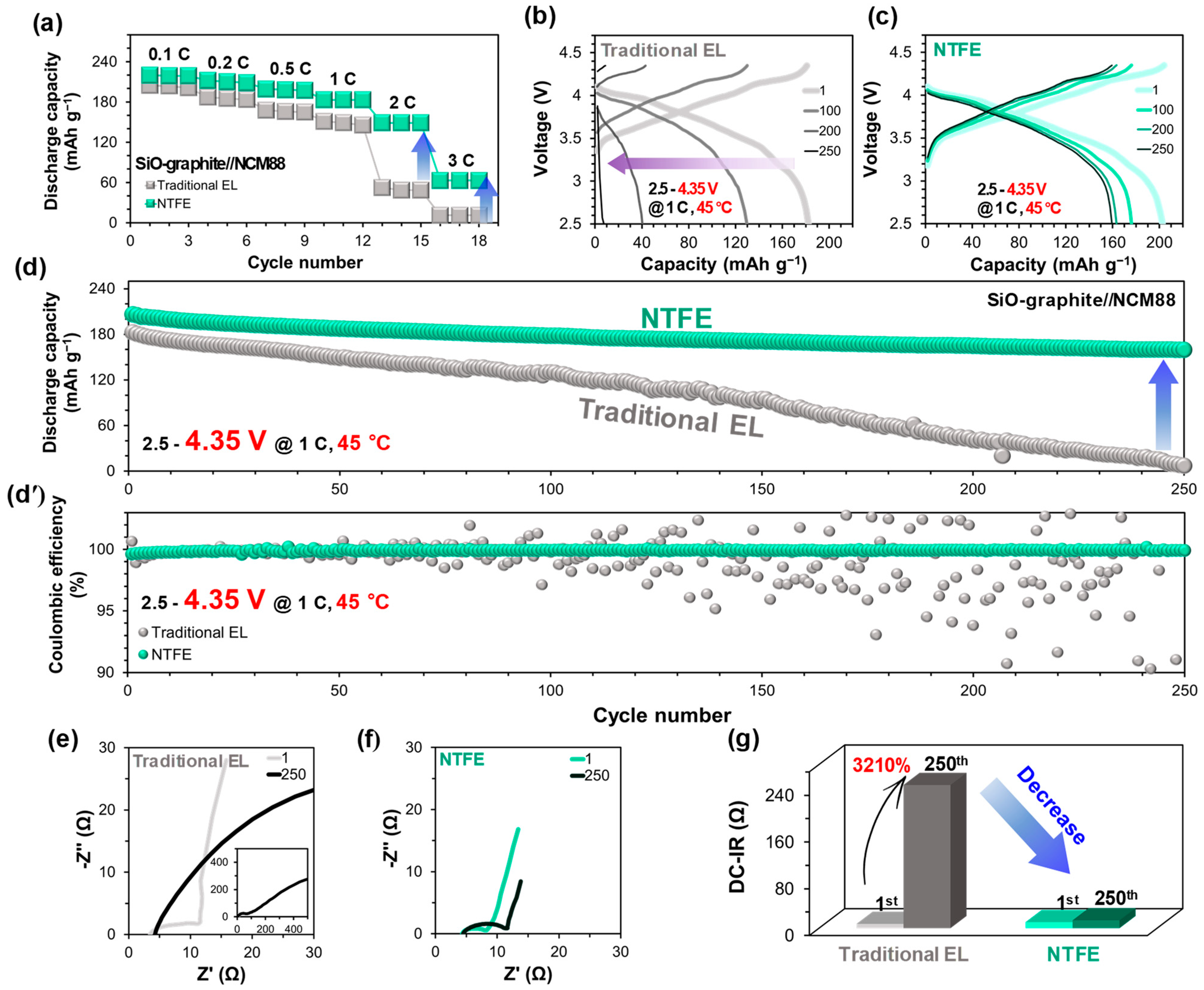
3.1. NTFE-Induced Performance Improvement and Resistance Reduction

The optimum amounts of VC and FEC additives for NTFE were determined as 2 wt% for each (Figure S1). To examine the applicability of NTFE to a highly loaded 3.5 mAh cm−2 SiO-based full cell, a cycle test was conducted between 2.5 and 4.35 V at 45 °C. The rate capability (Figure 2a) of the full cell with NTFE is superior to the one with the traditional EL. The full cell with NTFE exhibits a 50~100 mAh g−1 higher discharge capacity than that with the traditional EL, even at high charge rates of 2 C and 3 C. Figure 2b,c exhibit the electrochemical charge–discharge curves of SiO–graphite//NCM88 Li-ion full cells with the traditional EL or NTFE at 1 C. While NTFE (Figure 2c and Figure S2) remarkably improves the reaction reversibility, the capacity fades irreversibly and rapidly with the traditional EL (Figure 2b and Figure S2). Upon using NTFE (Figure 2d,d’), an exceptionally stable cycling performance with capacity retention of 80% after 250 cycles is achieved, delivering a high initial discharge capacity of ≈206 mAh g−1 and stably maintaining ≈100% cyclic Coulombic efficiencies throughout cycling. In contrast, the full cell with the traditional EL (Figure 2d,d’) shows a far lower initial discharge capacity of 182 mAh g−1 and a rapid capacity fade with very unstable cyclic Coulombic efficiencies. The replacement of the electrolyte with NTFE enables dramatically improved and stabilized cycling performance of the SiO–graphite//NCM88 full cell.
Cell resistance, in general, exhibits an inverse relationship with electrochemical performance and is used as a relative measure of performance. Changes in the interfacial resistance and internal cell resistance were examined using electrochemical impedance spectroscopy (EIS) (Figure 2e,f) and DC-IR (Figure 2g), respectively. The full cell with the traditional EL (Figure 2e,g) shows largely increased interfacial resistance and a huge increase (3210%) in DC-IR with 250 cycles, respectively. This is probably mainly due to swelling, damage to the SEI layer, and degradation of the SiO–graphite anode. However, with NTFE (Figure 2f), a significant decrease in the interfacial resistance after 250 cycles is observed, compared to that of the traditional EL. DC-IR is also significantly reduced to the 0.01-fold level (31%) of the traditional EL, which implies the effective suppression of anode issues. The results show the effectiveness of NTFE in increasing initial capacity, significantly improving capacity retention while reducing interfacial and cell resistances.

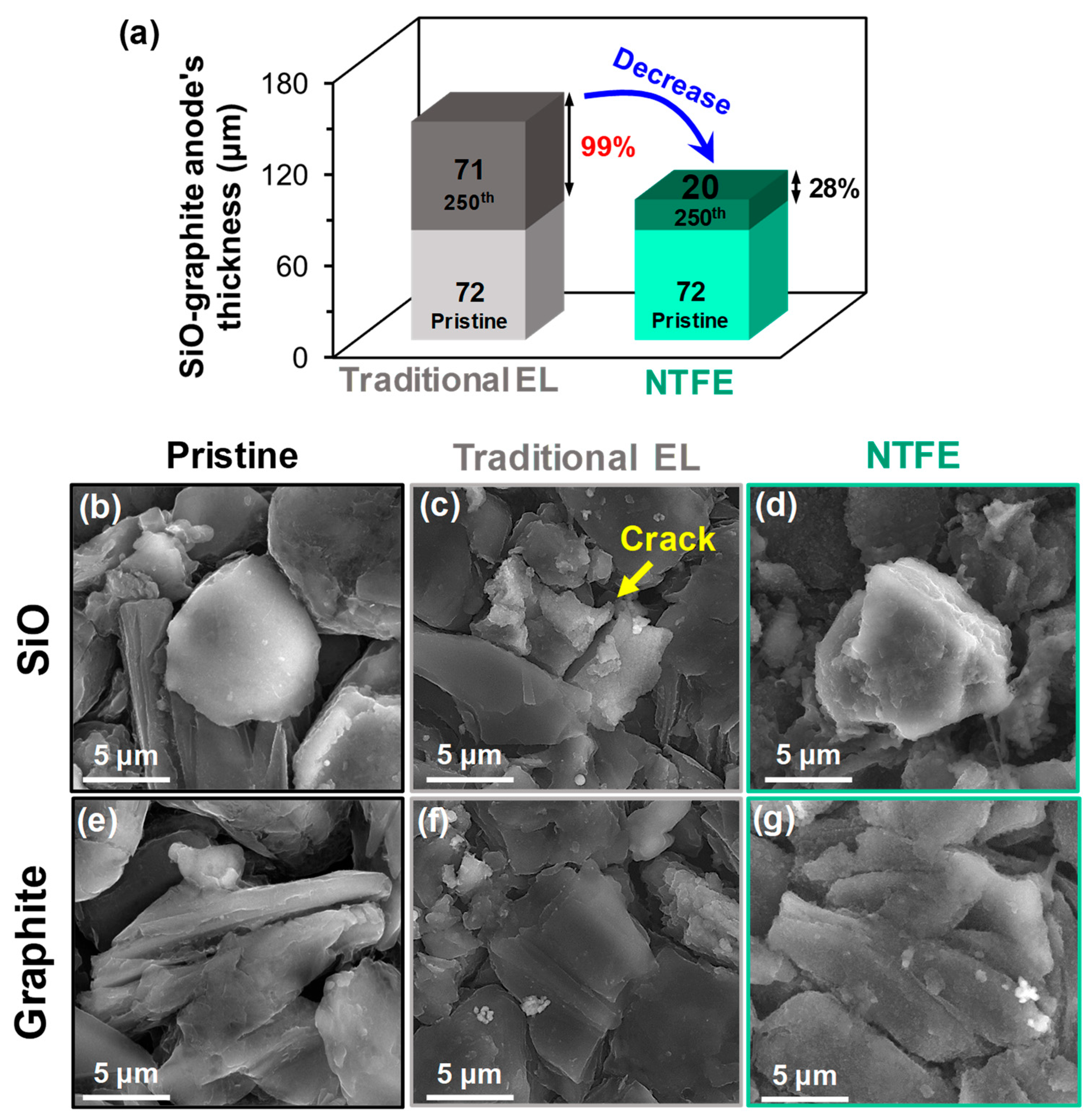
3.2. Suppressed Swelling of the SiO–graphite Anode by a Uniform and Robust SEI Layer

Swelling of the SiO-based anode during cycling is a signature of cell failure and poses risks of short circuits and thermal runaway [8,19,27]. If the SEI layer is unstable and nonuniform with low surface coverage and poor mechanical strength, it is subject to damage during the volume expansion and contraction of SiO. To examine the swelling phenomena of the SiO–graphite anode, we opened the full cells in the glove box and directly measured the thickness change of the anode using a micrometer. Cycling in traditional EL (Figure 3a) results in a 99% increase in the thickness, from 72 μm of pristine to 143 μm of the 250-cycled anode. However, the use of NTFE (Figure 3a) results in suppressing the thickness change to a ≈1/3-fold level (28%, 92 μm) compared to that with the traditional EL. The NTFE-induced significant suppression of swelling reduces the risk of short circuits and thermal runaway, leading to improved safety. This is also one of the reasons for the improved cycling performance (Figure 2). The SEM images of the cycled anodes in traditional EL (Figure 3c,f) clearly show the occurrence of cracks on SiO particles, compared to the pristine (Figure 3b,e), whereas the cycled anode with NTFE (Figure 3d,g) is crack-free. In particular, the surface of the anode with NTFE (Figure 3d,g) is uniformly and fully covered by a thin SEI layer, which is correlated with the suppressed interfacial resistance (Figure 2) and swelling (Figure 3a).
To examine the formation of SEI species on the anodes as a function of the electrolyte, XPS analysis was conducted. Changes in the chemical state of the surface SiO–graphite anode with cycling are first detected in the Si 2p spectra (Figure 4a). After cycling with the traditional EL (Figure 4a-ii), the spectral feature of pristine (Figure 4a-i) is notably weakened. This is due to the thickening of the SEI layer, which is cross-confirmed with the largely strengthened peaks of the SEI species in the C 1s and P 2p spectra (Figure S3). With NTFE (Figure 4a-iii), the peak of SiO in the pristine [19] is still detected, which is related to a relatively thinner SEI layer. A little SiO existed along with a lithiated phase (LixSiOy) (Figure 4a-ii,iii,c-ii,iii), implying that Li is irreversibly trapped. A strong peak of a new SiOxFy species is apparent, consistent with the F 1s and O 1s spectra (Figure 4b and Figure S3) [28,29]. The F 1s spectrum of the cycled anode with NTFE (Figure 4b-iii) exhibits a prominent peak of LiF as a major SEI species, consistent with the Li 1s spectra (Figure 4c), with a significantly higher concentration than in traditional EL (Figure 4b-ii). The TFA solvent and FEC additive play a critical role in the fluorination of the anode surface [18,23,25], as expected. The Li 1s spectra reveal the presence of surface Li2O and LixSiOy (Figure 4a,c and Figure S3), which are well-known intermediate compounds formed during the lithiation of silicon oxide [8,19,29]. In general, the inorganic-enriched SEI layer might be mechanically more stable and rigid (i.e., robust) than an organic-dominant one [18,19,25,26,28,29,30], contributing to the suppression of anode swelling (Figure 3) and the enhancement of interfacial stability with the electrolyte. As a result, prolonged cycling even under ambient pressure (Figure 2) is enabled, without external pressure.
The metal dissolution–deposition phenomena were examined on the cycled NCM88 cathodes using the Ni 2p, Co 2p, and Mn 2p XPS spectral analyses. It was established that dissolved metals from the NCM cathode are transported to the anode side and deposited on the surface of the anode [23,30]. The cycled anode in the traditional EL (Figure 4d-ii,f-ii) reveals deposited Ni and Mn species, which are originally dissolved from the NCM88 cathode [23,25,30]. This was a bad sign, indicating cathode degradation, impedance rise, and ultimately, performance fade (Figure 2). Their presence at the anode surface could also block Li+ ion diffusion to SiO and graphite anode active materials, and cause unknown side reactions with electrolytes. However, with NTFE, few of those are traced (Figure 4d-iii,f-iii), implying the mitigation of metal dissolution.

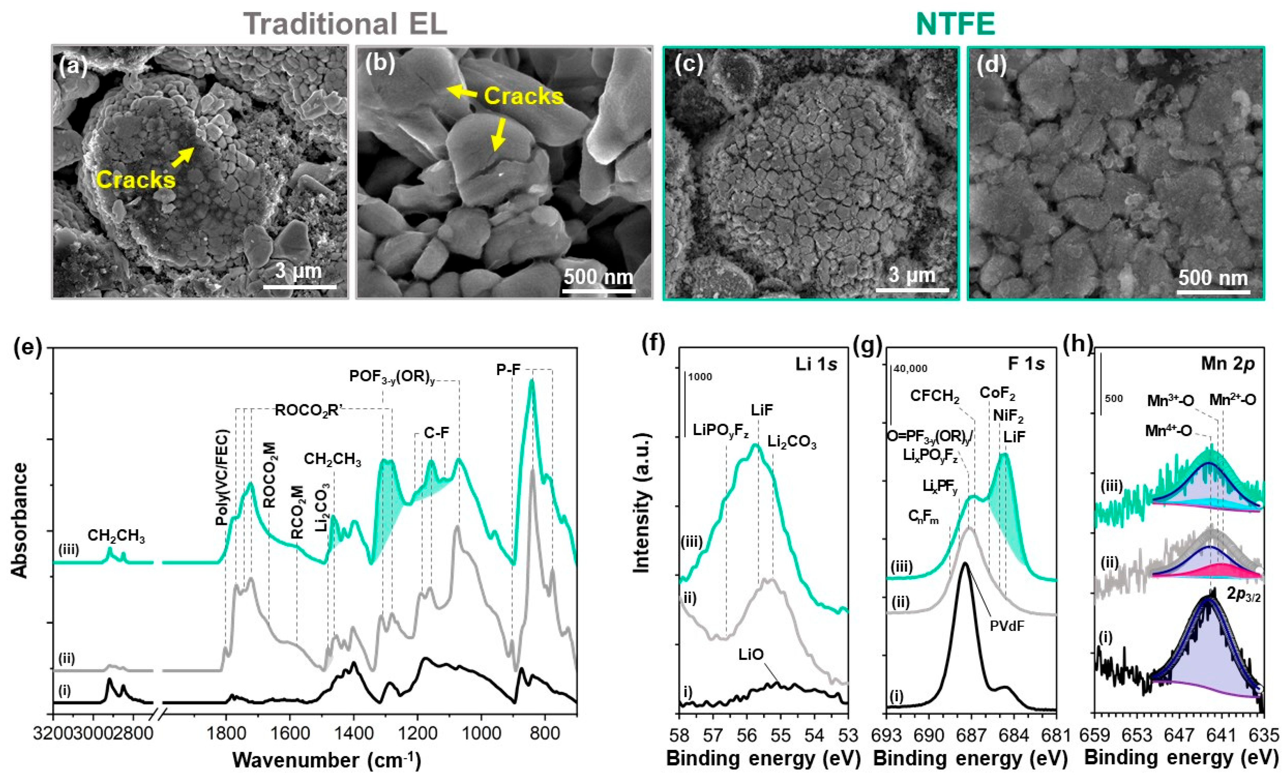
3.3. Mitigated Surface Changes and Metal Dissolution on the NCM88 Cathode via SEI Stabilization

To confirm the effect of NTFE on metal dissolution, surface and morphology analyses on the cycled NCM88 cathodes of full cells were carried out. SEM imaging reveals that severe cracks are present on both secondary (Figure 5a) and primary (Figure 5b) particles of the cycled cathode with the traditional EL, compared to pristine (Figure S4). Cracks represent electrical and mechanical disintegration as well as the occurrence of metal dissolution, causing resistance rise and performance fade (Figure 2). In addition, cracks permit electrolytes to infiltrate into the voids and to undergo new oxidative decomposition at the cathode–electrolyte interface, leading to the propagation of metal dissolution and cracks from surface to bulk [30,31,32]. On the other hand, particles of the cycled cathode with NTFE (Figure 5c,d) are crack-free on both secondary and primary particles, but their surface is fully covered with a uniform SEI layer.
ATR FTIR and XPS analyses were employed to characterize the SEI species formed on NCM88 cathodes. FTIR (Figure 5e) spectral comparison of the pristine and cycled cathodes reveals common new peaks of mainly various ester compounds [12,19,33], along with alkyl carbonate salts (ROCO2Mn+, M = Li/Ni/Co/Mn) [19,23,33], and carboxylate salts (RCO2Mn+) [23,25,33] as organic SEI species, which are confirmed by the C 1s and O 1s XPS spectra (Figure S5). In particular, the spectral feature of fluorinated species, such as organic phosphorus fluorides (POF3−y(OR)y), is significant when using NTFE (Figure 5e-iii) [25,30]. The F-containing species were observed in XPS spectra (Figure 5f,g). In the Li 1s spectra (Figure 5f), LiF is the major Li-containing species, consistent with the F 1s spectra (Figure 5g). The strong shoulder in the F 1s spectrum of NTFE (Figure 5g-iii) is attributed to metal fluorides (MF2, M = Ni, Co), which is absent in the one cycled with the traditional EL. Considering that NTFE and traditional EL include the same additives, those metal fluorides must come from the TFA solvent [25,26]. The formation of MF2 plays a crucial role in immobilizing metal atoms, particularly Ni, preventing their dissolution into the electrolyte. Those inorganic species also make the SEI robust. Unfortunately, peaks in the Ni and Co spectra notably weaken after cycling with NTFE (Figure S5), probably owing to an increase in SEI thickness and/or coverage, and the measurement of a weaker X-ray energy source (Mg source), which does not permit curve fitting for the study of chemical state changes during cycling. Nonetheless, clear Mn spectral features still allow curve fitting on the Mn 2p2/3 peak. Curve fitting was conducted by employing splitting patterns corresponding to Mn2+-O (641.0 eV), Mn3+-O (641.7 eV), and Mn4+-O (642.7 eV), based on standard compounds of MnO, Mn2O3, and MnO2, respectively [25,30,34,35]. Note that Mn2+-O is soluble in electrolytes. Thus, the formation of surface Mn2+-O with cycling and an increase in the fraction of surface Mn2+-O at the expense of pristine Mn4+-O are signatures of metal dissolution from the NCM88 cathode. These phenomena occur along with oxygen release to maintain the charge neutrality of the NCM88 active material, and lead to structural degradation and crack formation in the cathode [12,19,32,36]. Curve-fitting results for the pristine cathode (Figure 5h-i and Table 1) indicate that the surface of the NCM88 cathode has 100% Mn4+-O. Cycling in traditional EL (Figure 5h-ii and Table 1) results in a decrease in the fraction of Mn4+-O to 67%, while the lower-valent Mn atom formed as 4% Mn3+-O and 29% Mn2+-O. With the use of NTFE (Figure 5h-iii and Table 1), the higher fraction of Mn4+-O (83%) is maintained, with relatively lower fractions of Mn3+-O (15%) and Mn2+-O (2%). The data suggest that NTFE helps suppress the surface reduction of Mn4+-O to soluble Mn2+-O, mitigating metal dissolution [14,15,30,36]. Metal dissolution from the cathode was indirectly observed through the deposition of metal species on the anode (Figure 4). The surface analysis results of the cathode indicate that metal dissolution from the cathode is dramatically mitigated via an NTFE-derived robust SEI layer enriched with fluorinated inorganics.

4. Conclusions

We demonstrated the applicability of a nonflammable tri-fluorinated ester–based electrolyte (NTFE) formulation to a highly loaded SiO–graphite//NCM88 full cell, and significantly improved cycling stability, delivering a high initial capacity of ≈206 mAh g−1 and 80% capacity retention after 250 cycles, even under aggressive conditions of high voltage (4.35 V), high rate (1 C), and high temperature (45 °C), in contrast to the unstable cycling behavior of the full cell with the traditional EL. NTFE enables the formation of uniform and robust SEI layers that simultaneously passivate the surfaces of both the SiO–graphite anode and NCM88 cathode, leading to a reduction in the interfacial resistance and DC-IR of the full cell. As a result, swelling and cracking of the SiO-based anode are effectively suppressed, and metal dissolution and cracks in the cathode are mitigated as well. The results and discussion of the present study provide a promising strategy for the design of electrolytes and interfaces for long-cycled, safe, and high-energy LIBs consisting of a silicon-based anode and a high-nickel cathode.

Supplementary Materials

The following supporting information can be downloaded at https://www.mdpi.com/article/10.3390/batteries11070250/s1, Figure S1: (a) Cycling performance and (b) Coulombic efficiencies of SiO–graphite//NCM88 full cells with 1 M LiPF6/PC:TFA with 2 wt% FEC and variable amount of VC additives between 2.5 and 4.35 V at 1 C and 45 °C. Figure S2: dQ/dV plots of SiO–graphite//NCM88 full cells with (a) traditional EL and (b) NTFE between 2.5 and 4.35 V at 1 C and 45 °C. Figure S3: XPS (a) C 1s, (b) P 2p, and (c) O 1s spectra of (i) pristine and cycled SiO–graphite anodes from 250 cycled SiO–graphite//NCM88 full cells with (ii) traditional EL and (iii) NTFE between 2.7 and 4.3 V at 1 C and 45 °C. Figure S4: SEM images of (a) secondary and (b) primary particles of the pristine NCM88 cathode. Figure S5: XPS (a) C 1s, (b) O 1s, (c) P 2p, (d) Ni 2p, and (e) Co 2p spectra of (i) pristine and cycled NCM88 cathodes from 250 cycled SiO–graphite//NCM88 full cells with (ii) traditional EL and (iii) NTFE between 2.7 and 4.3 V at 1 C and 45 °C.

Author Contributions

Conceptualization, S.-W.S. and K.A.; methodology, S.-W.S. and K.A.; formal analysis, Y.H.T.T., D.G.K. and K.A.; data curation, K.A.; writing—original draft preparation, K.A.; writing—review and editing, S.-W.S., Y.H.T.T. and D.G.K.; visualization, K.A. and D.G.K. All authors have read and agreed to the published version of the manuscript.

Funding

This research received no external funding.

Data Availability Statement

The data that support the findings of this study are available in the supplementary material of this article.

Acknowledgments

This work was supported by the Samsung Electronics through the grant of Samsung Research Funding & Incubation Center for Future Technology (SRFC-MA2202-04).

Conflicts of Interest

The authors declare no conflicts of interest.

References

  1. Armand, M.; Tarascon, J.-M. Building Better Batteries. Nature 2008, 451, 652–657. [Google Scholar] [CrossRef] [PubMed]
  2. Placke, T.; Kloepsch, R.; Dühnen, S.; Winter, M. Lithium Ion, Lithium Metal, and Alternative Rechargeable Battery Technologies: The Odyssey for High Energy Density. J. Solid State Electrochem. 2017, 21, 1939–1964. [Google Scholar]
  3. Jin, Y.; Zhu, B.; Lu, Z.; Liu, N.; Zhu, J. Challenges and Recent Progress in the Development of Si Anodes for Lithium-Ion Battery. Adv. Energy Mater. 2017, 7, 1700715. [Google Scholar] [CrossRef]
  4. Ryu, J.H.; Kim, J.W.; Sung, Y.-E.; Oh, S.M. Failure Modes of Silicon Powder Negative Electrode in Lithium Secondary Batteries. Electrochem. Solid-State Lett. 2004, 7, A306–A309. [Google Scholar] [CrossRef]
  5. Weydanz, W.J.; Wohlfahrt-Mehrens, M.; Huggins, R.A. A Room Temperature Study of the Binary Lithium−Silicon and the Ternary Lithium−Chromium−Silicon System for Use in Rechargeable Lithium Batteries. J. Power Sources 1999, 81–82, 237–242. [Google Scholar] [CrossRef]
  6. Beattie, S.D.; Larcher, D.; Morcrette, M.; Simon, B.; Tarascon, J.-M. Si Electrodes for Li-Ion Batteries—A New Way to Look at an Old Problem. J. Electrochem. Soc. 2008, 155, A158–A163. [Google Scholar] [CrossRef]
  7. Li, X.; Gu, M.; Hu, S.; Kennard, R.; Yan, P.; Chen, X.; Wang, C.; Sailor, M.J.; Zhang, J.-G.; Liu, J. Mesoporous Silicon Sponge as an Anti-pulverization Structure for High-performance Lithium-Ion Battery anodes. Nat. Commun. 2014, 5, 4105. [Google Scholar] [CrossRef] [PubMed]
  8. Lim, G.; Kang, D.G.; Lee, H.G.; Tran, Y.H.T.; An, K.; Choi, J.; Roh, K.C.; Kim, D.Y.; Song, S.-W. Stable Operation of Highly Loaded Pure Si-Fe Anode under Ambient Pressure via Carboxy Silane-directed Robust Solid Electrolyte Interphase. J. Energy Chem. 2024, 94, 568–576. [Google Scholar] [CrossRef]
  9. Nadimpalli, S.P.V.; Sethuraman, V.A.; Dalavi, S.; Lucht, B.; Chon, M.J.; Shenoy, V.B.; Guduru, P.R. Quantifying Capacity Loss due to Solid-Electrolyte-Interphase Layer Formation on Silicon Negative Electrodes in Lithium-Ion Batteries. J. Power Sources 1999, 215, 145–151. [Google Scholar] [CrossRef]
  10. Xu, C.; Lindgren, F.; Philippe, B.; Gorgoi, M.; Björefors, F.; Edström, K.; Gustafsson, T. Improved Performance of the Silicon Anode for Li-Ion Batteries: Understanding the Surface Modification Mechanism of Fluoroethylene Carbonate as an Effective Electrolyte Additive. Chem. Mater. 2015, 27, 2591–2599. [Google Scholar] [CrossRef]
  11. Yang, J.; Takeda, Y.; Imanichi, N.; Capiglia, C.; Xie, J.Y.; Yamamoto, O. SiOx-Based Anodes for Secondary Lithium Batteries. Solid State Ion. 2002, 152–153, 125–129. [Google Scholar] [CrossRef]
  12. Nguyen, C.C.; Choi, H.; Song, S.-W. Roles of Oxygen and Interfacial Stabilization in Enhancing the Cycling Ability of Silicon Oxide Anodes for Rechargeable Lithium Batteries. J. Electrochem. Soc. 2013, 160, A906–A914. [Google Scholar] [CrossRef]
  13. Yang, S.; Zhang, Y.; Li, Z.; Takenaka, N.; Liu, Y.; Zou, H.; Chen, W.; Du, M.; Hong, X.-J.; Shang, R.; et al. Rational Electrolyte Design to Form Inorganic–Polymeric Interphase on Silicon-Based Anodes. ACS Energy Lett. 2021, 6, 1811–1820. [Google Scholar] [CrossRef]
  14. Zhang, Y.; Du, N.; Yang, D. Designing Superior Solid Electrolyte Interfaces on Silicon Anodes for High-performance Lithium-Ion Batteries. Nanoscale 2019, 11, 19086–19104. [Google Scholar]
  15. Choi, S.; Kwon, T.-W.; Coskun, A.; Choi, J.W. Highly Elastic Binders Integrating Polyrotaxanes for Silicon Microparticle Anodes in Lithium Ion Batteries. Science 2017, 357, 279–283. [Google Scholar] [PubMed]
  16. Ratyński, M.; Hamankiewicz, B.; Krajewski, M.; Boczara, M.; Czerwiński, A. The Effect of Compressive Stresses on a Silicon Electrode’s Cycle Life in a Li-Ion Battery. RSC Adv. 2018, 8, 22546–22551. [Google Scholar] [CrossRef] [PubMed]
  17. Choi, N.-S.; Yew, K.H.; Lee, K.Y.; Sung, M.; Kim, H.; Kim, S.-S. Effect of Fluoroethylene Carbonate Additive on Interfacial Properties of Silicon Thin-film Electrode. J. Power Sources 2006, 161, 1254–1259. [Google Scholar] [CrossRef]
  18. Jo, H.; Kim, J.; Nguyen, D.T.; Kang, K.K.; Jeon, D.M.; Yang, A.-R.; Song, S.-W. Stabilizing the Solid Electrolyte Interphase Layer and Cycling Performance of Silicon–Graphite Battery Anode by Using a Binary Additive of Fluorinated Carbonates. J. Phys. Chem. C 2016, 120, 22466–22475. [Google Scholar] [CrossRef]
  19. Oh, M.-G.; Kwak, S.; An, K.; Tran, Y.H.T.; Kang, D.G.; Park, S.J.; Lim, G.; Kim, K.; Lee, Y.S.; Song, S.-W. Perfluoro Macrocyclic Ether as an Ambifunctional Additive for High-Performance SiO and Nickel 88%-based High-Energy Li-Ion Battery. Adv. Funct. Mater. 2023, 33, 2212890. [Google Scholar] [CrossRef]
  20. Hu, Z.; Zhao, L.; Jiang, T.; Liu, J.; Rashid, A.; Sun, P.; Wang, G.; Yan, C.; Zhang, L. Trifluoropropylene Carbonate-Driven Interface Regulation Enabling Greatly Enhanced Lithium Storage Durability of Silicon-Based Anodes. Adv. Funct. Mater. 2019, 29, 1906548. [Google Scholar] [CrossRef]
  21. Han, G.-B.; Lee, J.-N.; Choi, J.W.; Park, J.-K. Tris(pentafluorophenyl) Borane as an Electrolyte Additive for High Performance Silicon Thin Film Electrodes in Lithium Ion Batteries. Electrochim. Acta 2011, 56, 8997–9003. [Google Scholar] [CrossRef]
  22. Lee, S.J.; Han, J.-G.; Lee, Y.; Jeong, M.-H.; Shin, W.C.; Ue, M.; Choi, N.-S. A bi-Functional Lithium Difluoro(oxalato)borate Additive for Lithium Cobalt Oxide/Lithium Nickel Manganese Cobalt Oxide Cathodes and Silicon/Graphite Anodes in Lithium-Ion Batteries at Elevated Temperatures. Electrochim. Acta 2014, 137, 1–8. [Google Scholar] [CrossRef]
  23. Nguyen, D.-T.; Kang, J.; Nam, K.-M.; Paik, Y.; Song, S.-W. Understanding Interfacial Chemistry and Stability for Performance Improvement and Fade of High-energy Li-Ion Battery of LiNi0.5Co0.2Mn0.3O2//Silicon-Graphite. J. Power Sources 2016, 303, 150–158. [Google Scholar] [CrossRef]
  24. De Sutter, L.; Berckmans, G.; Marinaro, M.; Wohlfahrt-Mehrens, M.; Berecibar, M.; Van Mierlo, J. Mechanical Behavior of Silicon-Graphite Pouch Cells under External Compressive Load: Implications and Opportunities for Battery Pack Design. J. Power Sources 2020, 451, 227774. [Google Scholar] [CrossRef]
  25. An, K.; Tran, Y.H.T.; Kwak, S.; Han, J.; Song, S.-W. Design of Fire-Resistant Liquid Electrolyte Formulation for Safe and Long-Cycled Lithium-Ion Batteries. Adv. Funct. Mater. 2021, 31, 2106102. [Google Scholar] [CrossRef]
  26. Zeng, Z.; Jiang, X.; Wu, B.; Xiao, L.; Ai, X.; Yang, H.; Cao, Y. Bis(2,2,2-trifluoroethyl) methylphosphonate: An Novel Flame-retardant Additive for Safe Lithium-ion Battery. Electrochim. Acta 2014, 129, 300–304. [Google Scholar] [CrossRef]
  27. Li, X.; Yan, P.; Xiao, X.; Woo, J.H.; Wang, C.; Liu, J.; Zhang, J.G. Design of Porous Si/C–Graphite Electrodes with Long Cycle Stability and Controlled Swelling. Energy Environ. Sci. 2017, 10, 1427–1434. [Google Scholar] [CrossRef]
  28. Philippe, B.; Dedryvère, R.; Gorgoi, M.; Rensmo, H.; Gonbeau, D.; Edström, K. Role of the LiPF6 Salt for the Long-Term Stability of Silicon Electrodes in Li-Ion Batteries—A Photoelectron Spectroscopy Study. Chem. Mater. 2013, 25, 394–404. [Google Scholar] [CrossRef]
  29. Philippe, B.; Dedryvère, R.; Allouche, J.; Lindgren, F.; Gorgoi, M.; Rensmo, H.; Gonbeau, D.; Edström, K. Nanosilicon Electrodes for Lithium-Ion Batteries: Interfacial Mechanisms Studied by Hard and Soft X-ray Photoelectron Spectroscopy. Chem. Mater. 2012, 24, 1107–1115. [Google Scholar] [CrossRef]
  30. Tran, Y.H.T.; An, K.; Lim, G.; Kim, D.; Lee, Y.J.; Doh, C.; Song, S.-W. Preventing Thermal Runaway of High-nickel Li-ion battery through Nonflammable Carbonates-based Electrolyte Formulation. Mater. Sci. Eng. R Rep. 2025, 164, 100980. [Google Scholar] [CrossRef]
  31. Chung, G.J.; Han, J.; Song, S.-W. Fire-Preventing LiPF6 and Ethylene Carbonate-Based Organic Liquid Electrolyte System for Safer and Outperforming Lithium-Ion Batteries. ACS Appl. Mater. Interfaces 2020, 12, 42868–42879. [Google Scholar] [CrossRef] [PubMed]
  32. Ryu, H.-H.; Park, K.-J.; Yoon, C.S.; Sun, Y.-K. Capacity Fading of Ni-Rich Li[NixCoyMn1–x–y]O2 (0.6 ≤ x ≤ 0.95) Cathodes for High-Energy-Density Lithium-Ion Batteries: Bulk or Surface Degradation? Chem. Mater. 2018, 30, 1155–1163. [Google Scholar] [CrossRef]
  33. Socrates, G. Infrared Characteristic Group Frequencies: Tables and Charts, 2nd ed.; Wiley: Hoboken, NJ, USA, 1994. [Google Scholar]
  34. Wagner, C.D.; Riggs, W.M.; Davis, L.E.; Moulder, J.F. Handbook of X-Ray Photoelectron Spectroscopy; Perkin-Elmer Corp.: Minnesota, MN, USA, 1979. [Google Scholar]
  35. NIST X-Ray Photoelectron Spectroscopy Database. Available online: http://srdata.nist.gov/xps/ (accessed on 15 May 2024).
  36. Chung, G.J.; Tran, Y.H.T.; Han, J.; Kim, K.; Lee, Y.S.; Song, S.-W. Novel Additives-Package to Mitigate the Failure Modes of High-capacity LiNi0.82Co0.11Mn0.07O2-based Lithium-Ion Battery. Chem. Eng. J. 2022, 446, 137288. [Google Scholar] [CrossRef]
Figure 1. Schematic illustration of a crack-free SiO–graphite//NCM88 full cell with NTFE by forming uniform and robust SEI layers at both the anode and cathode, whereas the occurrence of severe swelling of the anode and metal dissolution of the cathode with the traditional electrolyte is due to unstable, non-uniform, and thick SEI layers.
Batteries 11 00250 g001
Figure 2. (a) Rate capability of 3.5 mAh cm−2 SiO–graphite//NCM88 full cells with the traditional EL or NTFE at variable rates from 0.1 C to 3 C between 2.5 and 4.35 V at 45 °C. Charge–discharge curves of SiO–graphite//NCM88 full cells with (b) traditional EL and (c) NTFE, and their (d) cycling performance and (d′) Coulombic efficiencies between 2.5 and 4.35 V at 1 C and 45 °C. Impedance spectral changes of the full cells with 250 cycles, with (e) traditional EL and (f) NTFE, and (g) the changes in their DC-IR with 250 cycles.
Batteries 11 00250 g002
Figure 3. (a) Changes in the thickness of SiO–graphite anodes with 250 cycles in traditional EL or NTFE. Particle morphology changes of SiO and graphite from (b,e) pristine to cycled anodes with (c,f) traditional EL and (d,g) NTFE, respectively.
Batteries 11 00250 g003
Figure 4. XPS (a) Si 2p, (b) F 1s, (c) Li 1s, (d) Ni 2p, (e) Co 2p, and (f) Mn 2p spectral changes from (i) pristine to cycled anodes with (ii) traditional EL and (iii) NTFE.
Batteries 11 00250 g004
Figure 5. SEM images for secondary and primary particles of NCM88 cathodes after cycling with (a,b) traditional EL and (c,d) NTFE, respectively. (e) ATR FTIR spectra and XPS (f) Li 1s, (g) F 1s, and (h) Mn 2p spectra of (i) pristine and cycled NCM88 cathodes with (ii) traditional EL and (iii) NTFE.
Batteries 11 00250 g005
Table 1. Curve-fitting results on the 2p3/2 peak of XPS Mn 2p spectra for pristine and cycled NCM88 cathodes with the traditional EL or NTFE.
Areal Ratio [%]Mn2+-OMn3+-OMn4+-O
Pristine00100
Traditional EL29467
NTFE21583
Disclaimer/Publisher’s Note: The statements, opinions and data contained in all publications are solely those of the individual author(s) and contributor(s) and not of MDPI and/or the editor(s). MDPI and/or the editor(s) disclaim responsibility for any injury to people or property resulting from any ideas, methods, instructions or products referred to in the content.

