Article

Enhancing Grid Stability in Microgrid Systems with Vehicle-to-Grid Support and EDLC Supercapacitors

by
Adrián Criollo
1,
Dario Benavides
2,3,
Paul Arévalo
1,3,*,
Luis I. Minchala-Avila
1 and
Diego Morales-Jadan
4
1
Department of Electrical Engineering, Electronics, and Telecommunications (DEET), Universidad de Cuenca, Cuenca 010101, Ecuador
2
Faculty of Systems, Electronics and Industrial Engineering, Universidad Técnica de Ambato, Ambato 180206, Ecuador
3
Department of Electrical Engineering, University of Jaén, 23700 Linares, Spain
4
Electrical Engineering Career, Circular Economy Laboratory-CIITT, Universidad Católica de Cuenca, Cuenca 010107, Ecuador
*
Author to whom correspondence should be addressed.
Batteries 2025, 11(6), 231; https://doi.org/10.3390/batteries11060231
Submission received: 10 May 2025 / Revised: 11 June 2025 / Accepted: 12 June 2025 / Published: 15 June 2025
(This article belongs to the Special Issue Innovations in Batteries for Renewable Energy Storage in Remote Areas)

Abstract

Grid stability in microgrids represents a critical challenge, particularly with the increasing integration of variable renewable energy sources and the loss of systematic inertia. This study analyzes the use of vehicle-to-grid (V2G) technology and supercapacitors as complementary solutions to improve grid stability. A hybrid approach is proposed in which electric vehicles act as temporary storage units, supplying energy to regulate grid frequency. Supercapacitors, due to their rapid charging and discharging capabilities, are used to mitigate power fluctuations and provide immediate support during peak demand. The proposed management model integrates two strategies for frequency control, leveraging the linear relationship between power and frequency. Power smoothing is combined with Kalman filter-based frequency control, allowing for accurate estimation of the dynamic system state, even in the presence of noise or load fluctuations. This methodology improves grid stability and frequency regulation accuracy. A frequency variability analysis is also included, highlighting grid disturbance events related to renewable-energy penetration and demand changes. Furthermore, the effectiveness of the Kalman filter in improving grid stability control, ensuring an efficient dynamic response, is highlighted. The results obtained demonstrate that the combination of V2G and supercapacitors contributes significantly to reducing grid disturbances, optimizing energy efficiency, and enhancing system reliability.

1. Introduction

The increasing integration of renewable energy sources (RESs) into microgrids presents significant challenges to grid stability. The intermittent nature of RESs, such as solar and wind power, leads to fluctuations in power generation, potentially causing voltage instability and frequency deviations [1,2,3,4]. Furthermore, this leads to a loss of system inertia, which is primarily compromised by distributed generation resources (DERs). In traditional systems, the inertia provided by synchronous generators allows for the damping of frequency fluctuations in the presence of disturbances in the electrical grid. However, when RESs such as solar and wind power are incorporated through electronic converters, they do not contribute to the required inertia of the electrical system, which is considered a critical challenge for grid stability. This can generate greater volatility in the frequency and increase the rate of change of frequency (RoCoF) [5,6], which compromises the stability and security of the system. To mitigate these effects, several solutions have been proposed, such as synthetic inertia, the use of synchronous compensators, and, primarily, the integration of energy storage systems (ESSs) [4,7,8]. This allows for ensuring the stability and reliability of the supply.
In parallel, the integration of electric-vehicle charging stations (EVCSs) and their progressive incorporation into modern electrical systems has been analyzed. In this sense, grid-connected EVs can contribute to an emerging secondary benefit of using their batteries as energy storage assets and providing inertia to the electrical system, thereby improving its stability. These applications are known respectively as grid-to-vehicle (G2V) and vehicle-to-grid (V2G) [1,9,10,11,12,13]. The energy contribution of electric-vehicle batteries (EVBs) reduces the dependence on sintering of traditional synchronous generators in distributed energy resources (DERs). This enables more flexible and efficient operation in V2G applications. Similarly, disturbances caused by photovoltaic (PV) systems, wind turbines (WTs), and sudden load changes can be mitigated with this system. In addition, this approach offers opportunities for off-grid operation and improves the security of supply during grid disturbances [14]. On the other hand, integrating EVBs as dispatchable assets into broader energy systems requires the use of bidirectional electronic converters, allowing both charging and discharging to the power grid. This approach allows for validation of the detailed operation of the power converter controller and the overall system response under operational constraints on the stability and resilience of the power system.
Recent studies have shown that the incorporation of hybrid energy storage systems (HESSs) can significantly reduce battery degradation and improve energy efficiency. In this context, this study investigates the integration of supercapacitors (SCs) with EVBs to improve the performance of the proposed system, taking advantage of their high power density and rapid charge/discharge response. As a result, the incorporation of SCs and EVBs facilitates frequency stabilization, improving the transient response to load fluctuations.

1.1. Background and Literature Review

The transition toward power system models with a greater share of RESs, such as PV and WT, has led to a reduction in system inertia, affecting frequency stability [15,16,17,18]. One of the main consequences of this intermittency is the drastic rate of change in power generation, which can negatively impact the variation in the frequency of the electrical grid [3,4,7,19]. In countries where RESs have grown significantly, frequency recovery after imbalance events has been observed to be slower compared to that in systems that rely on conventional generation based on synchronous machines. This is due to the absence of rotating masses in RESs, which limits the system’s ability to withstand abrupt changes in frequency. To mitigate these effects, strategies such as the use of energy storage, rapid-response control, and demand-side management mechanisms have been implemented, seeking to improve dynamic stability and, primarily, the resilience of the electrical system.
In fact, ESSs include mechanical, electromagnetic, electrochemical, and phase-change energy storage systems. Electrochemical energy storage systems include metal-ion batteries [20], electric double-layer capacitors (EDLCs) [21], pseudo-capacitors, [22] and systems using water-in-salt electrolytes (WiSEs) [23]. Their application in MGs also stands out, offering distinctive advantages [24,25]. Their high power density allows them to respond quickly to transient power fluctuations, effectively smoothing and mitigating the intermittency of RESs [26]. Unlike batteries, SCs have a longer lifespan and a high response rate in charging and discharging [24], which is ideal for managing high-frequency power variations. However, supercapacitors have a lower energy density compared to batteries [24]. Furthermore, the self-discharge effect limits their capacity for long-term energy storage. This limitation can be addressed by HESSs that integrate SCs with batteries, combining the strengths of both technologies [27]. Several studies have demonstrated the effectiveness of HESSs in improving MG stability [28,29]. This research highlights the importance of effective control strategies to optimize HESS performance within MGs.
In [26], it is established that the participation of ESSs as frequency regulators requires fast dynamic responses. Therefore, the hybrid combination with SCs allows for optimization of the charge and discharge cycles to mitigate fluctuations. In addition, SCs have a long life cycle that makes them ideal for handling the high-frequency power components of the load [27]. The hybrid combination is able to reduce the battery temperature, addressing a current limitation of SCs. Another approach involves adaptive power smoothing based on a hybrid energy storage system. Although the specific study that investigated this approach focused on dP/dt, the influence of load variation and, consequently, its frequency stability in a distributed system was not considered [29]. On the other hand, to mitigate the impact of frequency stability, the implementation of fuel cells in hybrid SC and battery systems has been proposed as an alternative to reduce the environmental impact in a DC network [28]. Similarly, the proposed BESS and SC approach indirectly improves the transient response and voltage quality of systems in a DC network [30].
Although the integration of SCs and V2G represents a promising opportunity, it still faces significant challenges. One of the most critical is the development of advanced control and optimization algorithms that are capable of efficiently managing the complex interactions between various energy storage technologies and V2G resources, ensuring stable operation and maximizing performance [31]. Effective control strategies are crucial to maximize the benefits of SCs in MGs. These strategies are designed to optimize power distribution between the SCs and other ESS components, ensuring uninterrupted operation and avoiding state-of-charge (SoC) restrictions [30,32]. Model predictive control (MPC) is emerging as an effective technique for managing HESSs in DC MGs. Abadi et al. [30] proposed an MPC strategy that works in conjunction with a high-pass filter to allocate currents between the battery and the SC. This approach ensures continuous operation of the SC even under large and sudden load changes, improving the transient response and voltage quality. Furthermore, more accurate battery degradation models that consider both microcycle depth of discharge (DoD) and temperature effects [27] need to be developed. This is crucial for an accurate assessment of the economic benefits of hybridization and optimal control strategies for V2G operation. Similarly, the development of robust communication infrastructures for the seamless integration of V2G resources and efficient data exchange between EVs and the MG is crucial [33]. Exploring new optimization approaches, such as the multi-objective hunger game search optimizer (MOHGS) [34], and their integration with deep learning prediction models [35], could lead to more efficient and reliable energy management strategies. Lazarioiu et al., in [36], proposed a fuzzy logic-based controller to optimize electric-vehicle charging station (EVCS) selection. The proposed controller considers parameters such as distance, electricity price, and battery SOC to promote energy savings and improve efficiency. Ref. [11] proposes and evaluates three fuzzy logic-enhanced power smoothing techniques: V2GGlide (low-pass filter), V2GSUN (moving-average filter), and V2GSmooth (ramp-rate filter), integrated with a lithium-ion battery EES in the same line. These studies highlight the importance of research on hybrid systems that integrate V2G and SC technology in the context of DERs and their adoption in self-managed MGs. They also emphasize the importance of integrating ESSs as a backup to ensure the stability of grids with high RES penetration. Furthermore, they underscore the need for standardization and regulation to facilitate the widespread adoption of V2G technology, thus ensuring safe, reliable, and resilient operation of MGs with integrated V2G and SC systems.

1.2. Research Problem

The integration of V2G technology into modern power systems presents both opportunities and challenges for grid stability. While V2G enables bidirectional energy exchange between EVs and the grid—offering ancillary services such as frequency regulation, peak shaving, and load balancing—the inherently intermittent nature of EV participation, combined with response delays and battery degradation constraints, can compromise the system’s dynamic frequency response and inertial stability. One critical issue is that V2G systems alone lack the capability to deliver the instantaneous high-power responses required to counteract rapid frequency deviations following disturbances. Conventional battery-based V2G systems suffer from limited power density and a delayed response time, which restrict their effectiveness in fast frequency control and inertia emulation. A promising solution to this challenge is the integration of SCs into the V2G power grid. SCs possess a high power density, ultrafast response, and excellent charge/discharge cycle life, making them ideal for supporting power-seeking and virtual inertia-supporting rate-of-change response functions. By acting as an intermediate layer between the EVB and the grid, SCs can supply or absorb power in milliseconds, stabilizing voltage and frequency transients before the main battery switches to slower, more energy-intensive operations. The most representative studies in this field of research are detailed in Table 1.
The organization of this paper is as follows: Section 2 presents the methodology in detail. The results are presented in Section 3. Section 4 presents the discussion. Finally, Section 5 concludes the study.

2. Methodology

The structure of an MG includes an integrated renewable-energy generation, storage, and distribution system. Figure 1 shows a renewable generation system consisting of a photovoltaic P t P V system and wind turbines P t W T , which are represented as RESs. Another important component is the supercapacitor, represented as a storage medium to mitigate power fluctuations in the grid, and labeled P t S C . It also includes an EVCS, illustrated as a charging station. This also has storage functions and utilizes bidirectional energy from the EVB, represented as P t E V B .
The Point of Common Coupling (PCC), represented by an AC bus with a transformer, is connected with the energy sources, storage, and distribution system. The energy flowing into the grid is denoted as P t G d , and the energy demand of loads as P t L d s . The figure also shows the relationship between frequency f ( p u ) and power P ( p u ) . This graph underscores that power deviations ( Δ P ) must be kept within a specific range of ± 10 % of the nominal power P n o m i n a l [42]. Also highlighted are the values P 0 Δ P and P 0 + Δ P as the rate of change of the initial power P 0 versus a change in Δ P , which leads to frequency deviations 1 + Δ f and 1 Δ f in variations in the power of the grid. The main equation governing the energy distribution in this system is as follows:
P t G d = P t P V + P t W T ± P t S C ± P t E V B P t L d s , t { t Z t > 0 }
In summary, this system represents the integration of RESs and ESSs, which combine to ensure stability in the frequency and power supplied to the power grid. It also improves the resilience of the modern electrical system thanks to the functionality of EVBs. Consequently, the V2G configuration provides backup power to mitigate frequency variations in the power grid, offsetting the loss of inertia of the distributed system caused by the high penetration of renewable sources.

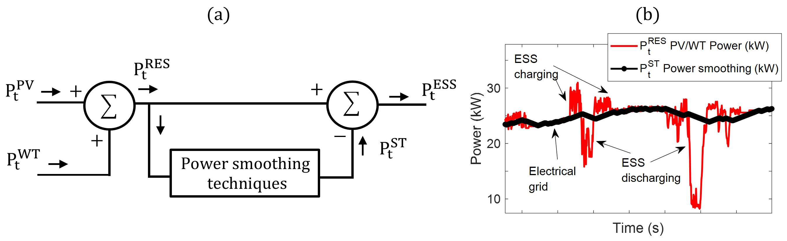
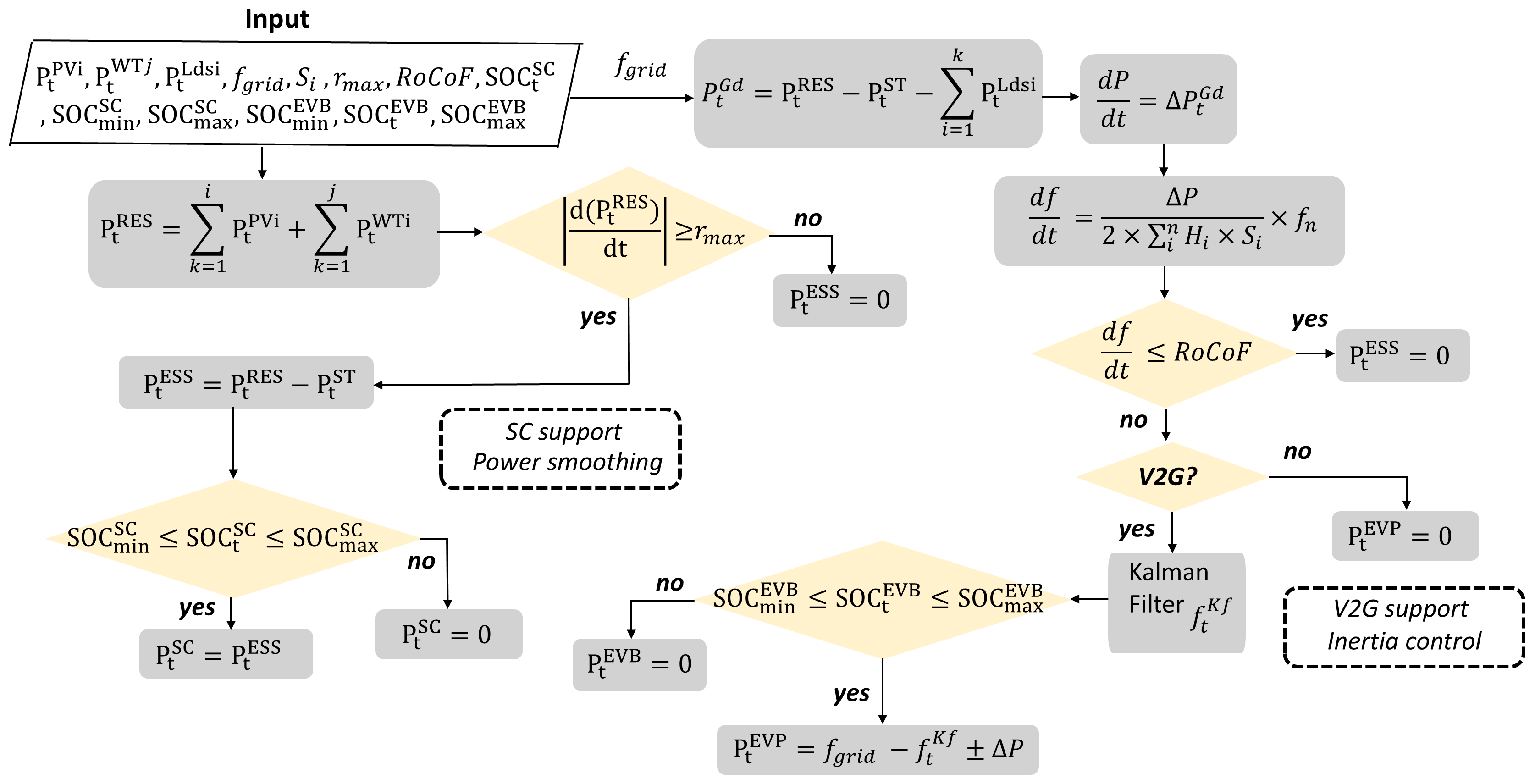
2.1. Power Smoothing Model and Rate of Change of Frequency (RoCoF)

PV and WT power generation systems have fluctuating output power due to their intermittent nature. Therefore, it is necessary to apply power smoothing methods before supplying energy to the grid for proper operation [2,39,43,44]. Power smoothing techniques have been widely studied as tools for reducing disturbances in the electrical grid. Equation (2) determines the total renewable power injected into the electrical system as the sum of the i PV systems and the j WT systems, considering the total number of renewable units present in the grid.
P t R E S = k = 1 i P t P V i + k = 1 j P t W T j , i , j { i , j Z i , j > 0 }
Figure 2a illustrates the operation of power smoothing techniques in renewable energy generation systems. The traditional block diagram describes the power flow from photovoltaic power P t P V and wind power P t W T , whose combination represents the total renewable power P t R E S . Subsequently, P t R E S is processed using power smoothing techniques P t S T ; the reference smooth power provided to the storage system is subtracted from the original signal to obtain P t E S S . This interpretation is shown in Equation (3).
P t E S S = P t R E S P t S T
where P t S T can be determined by a variety of different methods, such as SMA (Simple Moving Average), WMA (Weighted Moving Average), SES (Simple Exponential Smoothing), LPF (low-pass filter), and R-R (ramp-rate control), among others. For the focus of this article, the base model proposed by the authors in [45] is used, which stands out for its functionality with SC and optimal SOC control in energy storage. The control model for the maximum allowable rate of power change, r m a x which represents 10% of the system’s nominal power P n o m over a one-minute range, is described below.
r m a x = 0.1 × P n o m / 60
P t + 1 R E S P t R E S > r m a x
( P t + 1 R E S P t R E S ) > 0 , P t S T = ( P t + 1 R E S + r m a x )
( P t + 1 R E S P t R E S ) < 0 , P t S T = ( P t + 1 R E S r m a x )
The representation of power variation, expressed as d P / d t , must be adjusted to the values measured in real time. Therefore, it requires control within a narrow response range at two time instants, T t + 1 and T t . Furthermore, the rate of change R R t is limited to the maximum set value.
R R t = d P d t = ± P t + 1 R E S P t R E S T t + 1 T t
R R t r m a x
Consequently, Figure 2b presents the original signal P t R E S and the response signal to the smoothing method P t S T , expressed in kW. In addition, it includes the charging and discharging states of the storage system and its interaction with the electrical grid to mitigate fluctuations. This analysis summarizes the smoothing techniques that contribute to the stability and efficient integration of RESs in electrical systems.
On the other hand, the calculation of R o C o F in MGs and distributed generation systems follows principles similar to those of conventional systems, but with additional considerations due to the integration of renewable sources and inverter-based devices. This factor generally occurs immediately after a load disturbance, and depends on the average system inertia and the magnitude of the disturbance. Its estimate can be calculated using the following equation [5,6,46]:
R o C o F = d f d t = Δ P 2 × i n H i × S i × f n
H i = E k i n e t i c S S G i = J s w 2 2 × S S G i
where Δ P is the size of the disturbance (kW); H i is the inertia constant, expressed as the proportion of kinetic energy ( E k i n e t i c ); the generator power rating is expressed in seconds; S i is the nominal power of generator i in (kVA); f n is the nominal frequency (Hz); and J s is the moment of inertia, expressed in kg/m2.
In MGs and distributed generation systems, system inertia can be significantly lower due to the high penetration of RESs connected via inverters, which do not directly contribute to system inertia. This can result in higher RoCoF values during disturbances, as can the switching on and off of loads in the electrical system.

2.2. The V2G Strategy to Support the Power Grid

The proper sizing of ESSs is essential to minimize energy costs, accounting for both power and energy density relative to spatial constraints. Moreover, ESSs contribute to enhancing power quality in the electrical grid by enabling reactive power support and maintaining voltage and frequency stability. In MG configurations, EVCSs are typically connected with RESs and ESSs through either AC or DC. These configurations support bidirectional energy flow between the grid, ESS, and EVCS at the PCC. A wide range of storage technologies is employed in MGs, including lead–acid batteries, lithium-ion cells, ultracapacitors, vanadium redox flow batteries, and fuel cells, with each offering specific operational benefits. In this context, EVBs are also utilized as ESSs, supporting both V2G and G2V functionalities. Effective control and operation of these systems rely heavily on AC/DC and DC/DC power converters, whose performance must be managed within their rated power limits to ensure safe and efficient energy exchange [47].
The dynamic SOC of an EVB is given by
S O C n E V B = S O C n 1 E V B i · t Q 0
where
  • S O C n E V B is the state of charge at time n;
  • i is the battery current;
  • t is the time step;
  • Q 0 is the initial battery capacity.
The battery terminal voltage is described using Ohm’s law:
V = O C V ( S O C E V B ) i · R ( S O C E V B , T )
where
  • V is the terminal voltage;
  • O C V is the open-circuit voltage as a function of the SOC;
  • R is the internal resistance, dependent on the SOC and temperature T;
  • i is the current.

2.3. Battery Degradation Model

The degradation stress factor S F is given by
S F = L n · k = 1 n I p k
where I p k is the impact of parameters such as the average SOC, depth of discharge (DoD), C-rate, and temperature.
The actual degradation rate is computed as follows:
D R a c t u a l = D R r e f · S F
where
  • D R a c t u a l is the actual degradation rate;
  • D R r e f is the reference degradation rate;
  • S F is the stress factor.

2.4. Bidirectional AC/DC Converters

Bidirectional grid-connected AC/DC converters play a fundamental role in enabling V2G and G2V operations, as they facilitate controlled bidirectional power exchange between EVs and the electrical grid. The system model adopted employs an early decoupling strategy for grid voltage to improve control performance. The converter topology includes three-phase grid voltages and currents, denoted as e a , e b , e c and i a , i b , i c , respectively, to characterize the interaction between the converter and the grid interface [47].
e a = L d i a d t + R i a + u a N + u N O
e b = L d i b d t + R i b + u b N + u N O
e c = L d i c d t + R i c + u c N + u N O
The associated DC circuit is modeled as follows:
C d u d c d t = i d c i L
where
  • e a , b , c are the grid voltages per phase;
  • i a , b , c are the currents per phase;
  • u a N , u b N , u c N are the voltages between the midpoint of each phase and the neutral point;
  • u N O is the voltage between point N and point O;
  • L, R are the inductance and resistance of the filter;
  • u d c is the DC bus voltage, i d c is the DC bus current, and i L is the load current.
The control of the IGBT gates is defined as follows:
u k = u k N + u N O = S k u d c + u N O , k { a , b , c }
The three-phase system is transformed into the stationary reference frame d q :
e d = L d i d d t + R i d ω 0 L i q + S d u d c
e q = L d i q d t + R i q + ω 0 L i d + S q u d c
The power balance on the DC bus is given by
C d u d c d t = 3 2 ( i d S d + i q S q ) i L
In the converter model, L and R are the inductance and resistance of the grid filter. C denotes the DC-side capacitance. u d c and i d c represent the voltage and current on the DC side, respectively. The DC load is modeled by R L and e L , while i L is the load current.
The voltages u a N , u b N , u c N represent the phase-to-midpoint voltages, and u N O is the voltage between point N and the ground reference O. The IGBT switching logic is such that S k = 1 corresponds to an active state, and S k = 0 is inactive, where k { a , b , c } .
The instantaneous phase voltage u k is given by
u k = u k N + u N O = S k u d c + u N O
Using the Clarke–Park transformation, the three-phase system ( a , b , c ) is mapped into the orthogonal dq reference frame. According to [48], the resulting dynamic equations are
e d = L d i d d t + R i d ω 0 L i q + S d u d c , e q = L d i q d t + R i q + ω 0 L i d + S q u d c , C d u d c d t = 3 2 ( i d S d + i q S q ) i L
where
  • i d , i q are the currents in the d q frame;
  • S d , S q are the switching functions in the d q frame;
  • ω 0 is the angular frequency of the synchronous reference frame;
  • e d , e q are the d q components of grid voltage.

2.5. Storage Management Model

The proposed management model integrates two strategies for grid frequency control. Taking advantage of the linear relationship between power and frequency, it combines power smoothing with Kalman filter-based frequency control. This approach allows the state of a dynamic system to be estimated, even in the presence of noise or load fluctuations, improving regulation stability and accuracy. By incorporating V2G technology into the electrical system, EVs are able to contribute to system stability through battery-based storage. This significantly improves the system’s inertia in the face of grid disturbances, optimizing response and frequency regulation.
r m a x = 0.1 × P n o m / 60
P t + 1 R E S P t R E S > r m a x , t { x Z x > 1 } ( P t + 1 R E S P t R E S ) > 0 , P t S T = ( P t + 1 R E S + r m a x ) ( P t + 1 R E S P t R E S ) < 0 , P t S T = ( P t + 1 R E S r m a x )
The SOC calculation for SCs is determined by the energy stored during charging E c t S C and during discharging E d t S C . The reference power P t E S S is calculated from Equations (6) and (7) as follows:
P t E S S = P t R E S P t S T E c t S C = t 1 t 2 P t S C c h a r g e d t P t E S S 0 E d t S C = t 1 t 2 P t S C d i s c h a r g e d t P t E S S < 0
Consequently, the total energy stored in the SC during time t is determined as follows:
E t S C = η c S C × E c t S C 1 η d S C × E d t S C
where η c S C is the SC charging efficiency and η d S C is the SC discharging efficiency, respectively. The SOC (%) of the SC is calculated as follows:
S o C t S C = S o C t 1 S C + E m a x S C E t S C × 100 %
The SC SOC is restricted by maximum S o C m a x S C and minimum S o C m i n S C values, according to the following equation:
P t S C = P t E S S S o C m i n S C S o C t S C S o C m a x S C P t S C = 0 S o C m a x S C < S o C t S C < S o C m i n S C
On the other hand, the second strategy allows for frequency control with V2G support and incorporates demand response integration, as follows:
P t G d = P t R E S P t S T i = 1 k P t L d s i
d P d t = Δ P t G d d f d t = Δ P 2 × i n H i × S i × f n
Consequently, a comparison is made to ascertain whether the frequency variation exceeds the R o C o F value, i.e., d f / d t < R o C o F . In this case, operational charging stations for V2G operation are verified.
The equations used in the estimation and correction process based on the Kalman filter are as follows:
In the prediction approach, the estimated initial state is calculated as the initial value of the power grid frequency, that is, x s t a = f g r i d ( 1 ) . Then the prediction state vector x p r e d and the predicted error E p r e d are calculated as follows:
x pred = x sta E pred = E s t a + Q a d j
where E s t a is the initial estimation error and Q a d j is the smoothing adjustment coefficient.
The data are updated according to the Kalman Gain K g a i n , Estimated State x s t a , and Updated Estimation Error E u p d , calculated as follows:
K g a i n = E pred E pred + R t r u x sta = x pred + K g a i n · ( f g r i d x pred ) E u p d = ( 1 K g a i n ) · E pred
where E p r e d is the predicted error, R t r u is the confidence adjustment coefficient of the measured data, and f g r i d is the frequency of the power grid.
Finally, the adjustment to the nominal frequency f n o m is determined linearly with the state vector:
x sta = x sta + 0.1 · ( f n o m x sta )
f t K f = x sta
These equations represent the application of the Kalman filter with correction towards the 60 Hz reference. Then, to establish the SOC EVB control, the same charge and discharge limits are applied.
P t E V B = f g r i d f t K f ± Δ P S o C m i n S C S o C t S C S o C m a x S C P t E V B = 0 S o C m a x S C < S o C t S C < S o C m i n S C
The following Figure 3 summarizes the flow of the power–frequency control process based on power smoothing and frequency stability with SC and V2G systems, respectively.

3. Results and Case Study

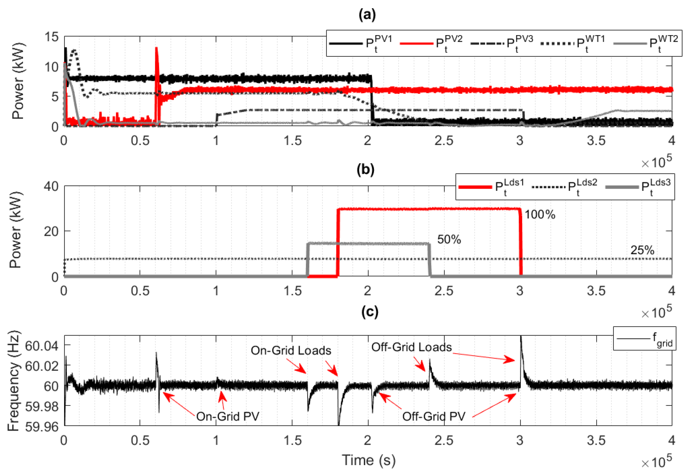
3.1. Microgrid Case Study

The University of Cuenca’s Microgrid Laboratory is proposed as a case study for testing and validating the results (See Figure 4) [49]. The photovoltaic systems consist of three units of 15 kW, 15 kW, and 5 kW; the wind systems consist of two 5 kW wind turbines. The SC storage system consists of 10 cells (130 farad) on a 560 Vdc bus bar. This system is connected to the electrical grid via a bidirectional DC/AC converter. A two-level, three-phase controlled bridge rectifier with Fsw = 2.5 kHz allows dual flow from the grid with a maximum capacity of 0.4 kWh. The nominal power of the SC is limited by the nominal capacity of the bidirectional converter at 50 kW. Additionally, an 11-cell lithium battery bank is used on a bus bar with a maximum voltage of 642 Vdc, producing 44 kWh of energy. This battery is used as an analog to an EVB with a similar capacity in the 39 kWh Ioniq EV model with a range of 300 km in the case study. It is also connected to the electrical grid via a bidirectional converter with similar characteristics to the SC. This configuration reflects the V2G experiment. The parameters of the microgrid components and equipment are detailed in Table 2 below. All the aforementioned systems are connected by a low-voltage PCC and a coupling transformer to the distribution electrical grid.

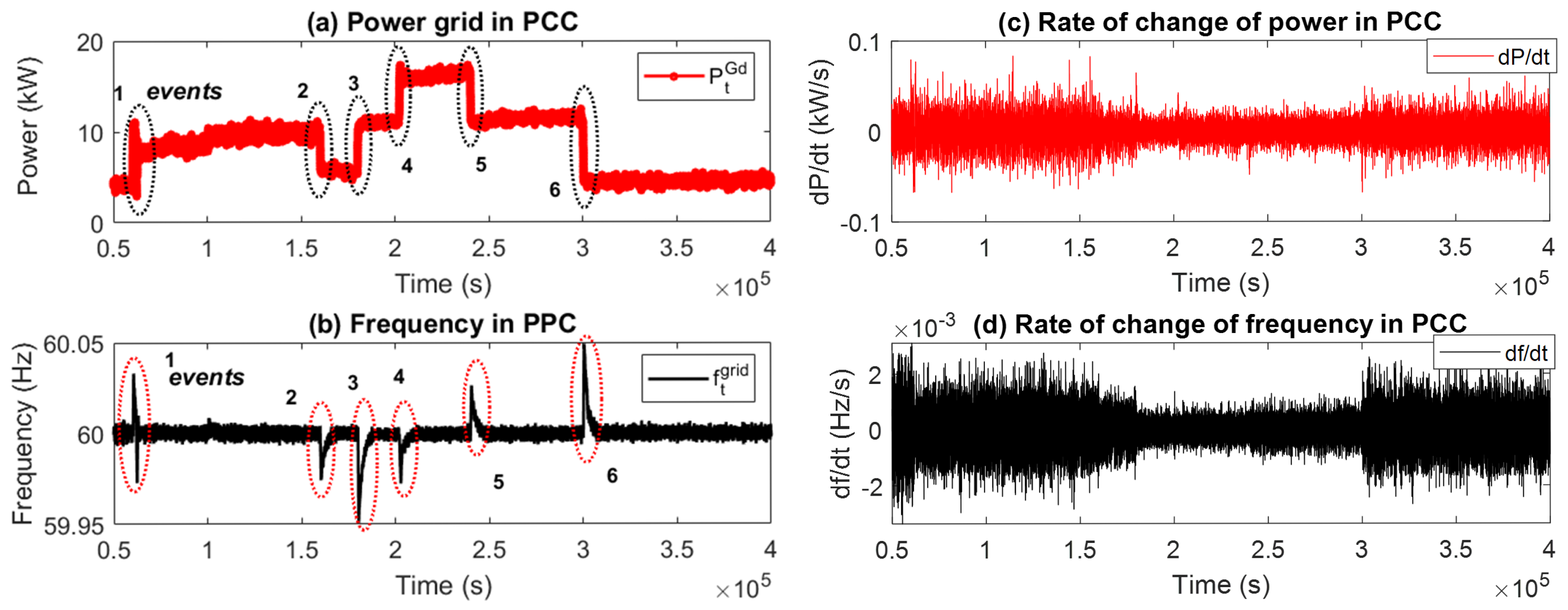
3.2. Power–Frequency Variability Analysis

Frequency stability is crucial for the safe and efficient operation of the grid, and deviations can lead to problems such as overloads, unplanned disconnections, and damage to electrical equipment. Mitigating these effects fundamentally requires the implementation of energy management and storage strategies that balance supply and demand, i.e., load management systems. In this context, Figure 5 presents the dynamic behavior of a grid-connected generator in the case study configuration, where the balance of generation, consumption, and frequency stability in a PCC is analyzed. The first graph details the power generated by several RESs, three different photovoltaic systems, and two small-capacity wind turbines, reflecting their contribution in kilowatts (kW) over time. Figure 5b represents the energy consumption of different loads and demand percentages in kW to analyze their impact on frequency stability. Finally, the grid frequency stability is presented, expressed on a 60 Hz grid, indicating critical events such as the connection or disconnection of grid-tied generator elements (See Figure 5c). This representative form of the grid-connected generator allows analysis of the interaction between its different components in terms of generation, consumption, and frequency, allowing for evaluation of the operational stability of the electrical system in the face of common disturbances.
In the frequency variability analysis, the behavior of some events linked to the penetration of RESs and load connection and disconnection states in the microgrid was studied. The measurement point was the PCC, where the power and frequency values were recorded. In accordance with the scenarios in Figure 5, six events were observed in the scenarios of disturbances in the electrical grid. These points are presented in Figure 6, where the power in the grid P t G d from Equation (1) and the frequency response f t g r i d can be seen in Figure 6a and Figure 6b, respectively. The detailed data are presented in Table 3, where these values are classified with respect to the events of 50% renewable penetration, 50% load connection, 100% load connection, 50% load disconnection, and 100% load disconnection, respectively. Furthermore, Figure 6c,d show the rate of change or derivative of the grid power d P / d t and the derivative of the grid frequency d f / d t . The similarities in the behavior and performance of these events could be analyzed by varying their power (kWs) and frequency (Hz/s) values. These parameters provide a quantitative perspective on operational dynamics, allowing response patterns to be identified and their impact on the system to be assessed. Consequently, the following section discusses the linearity factor with respect to these specific parameters and points of interest.
During the events indicated above, the values for the two time intervals t and t + 1 were obtained for the power P t and P t + 1 respectively. These values allowed us to evaluate the power’s rate of change or derivative as Δ P t . Similarly, the values obtained for the system frequency were f t , f t + 1 , and Δ f t .

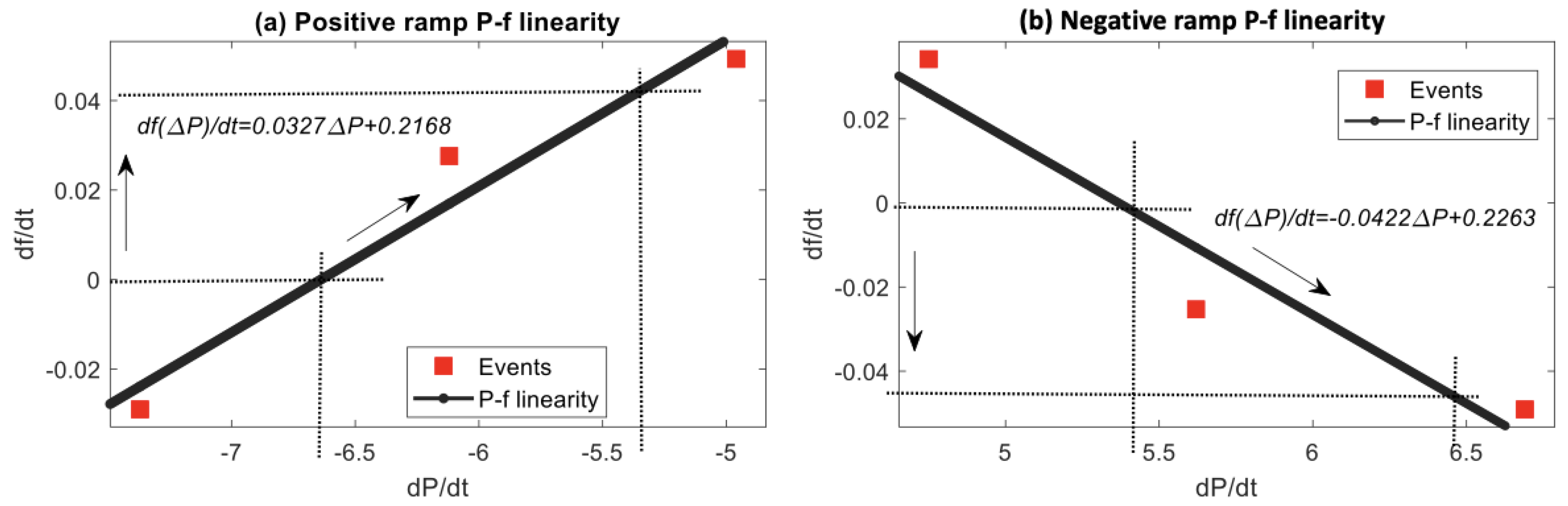
3.3. Power–Frequency Linear Estimation

Power–frequency linear estimation is a technique used in electrical and signal processing systems to accurately determine the frequency of a power signal. It allows for operational stability and the detection of potential fluctuations that could affect MG performance in real time. However, its determination depends on the characteristics of the electrical grid, which implies an analysis of the most common fluctuations in the MG. In this case, the positive ramp indicates that a power increase Δ P > 0 causes a positive change in frequency d f / d t . This typically simulates conditions like load disconnection or sudden PV/wind injection. On the other hand, the negative ramp illustrates how a drop in power Δ P < 0 causes a negative frequency deviation. This represents events such as load connection or loss of generation.. The following Figure 7 shows the events of load connection or generation losses, and load disconnection or generation connection respectively.
The negative slope (−0.0422 Hz/kW) means that an increase in power tends to cause a drop in Δ P 0 , which determines a response with a linear approximation. Consequently, the adjustment of d f / d t to d P / d t can be estimated according to the following equations for negative and positive rates of change, respectively.
If Δ P < 0 :
d f ( Δ P ) / d t = 0.0327 Δ P + 0.2168 Δ P = ( d f ( Δ P ) / d t 0.2168 ) / 0.0327
If Δ P > 0 :
d f ( Δ P ) / d t = 0.0422 Δ P + 0.2263 Δ P = ( 0.2263 d f ( Δ P ) / d t ) / 0.0422

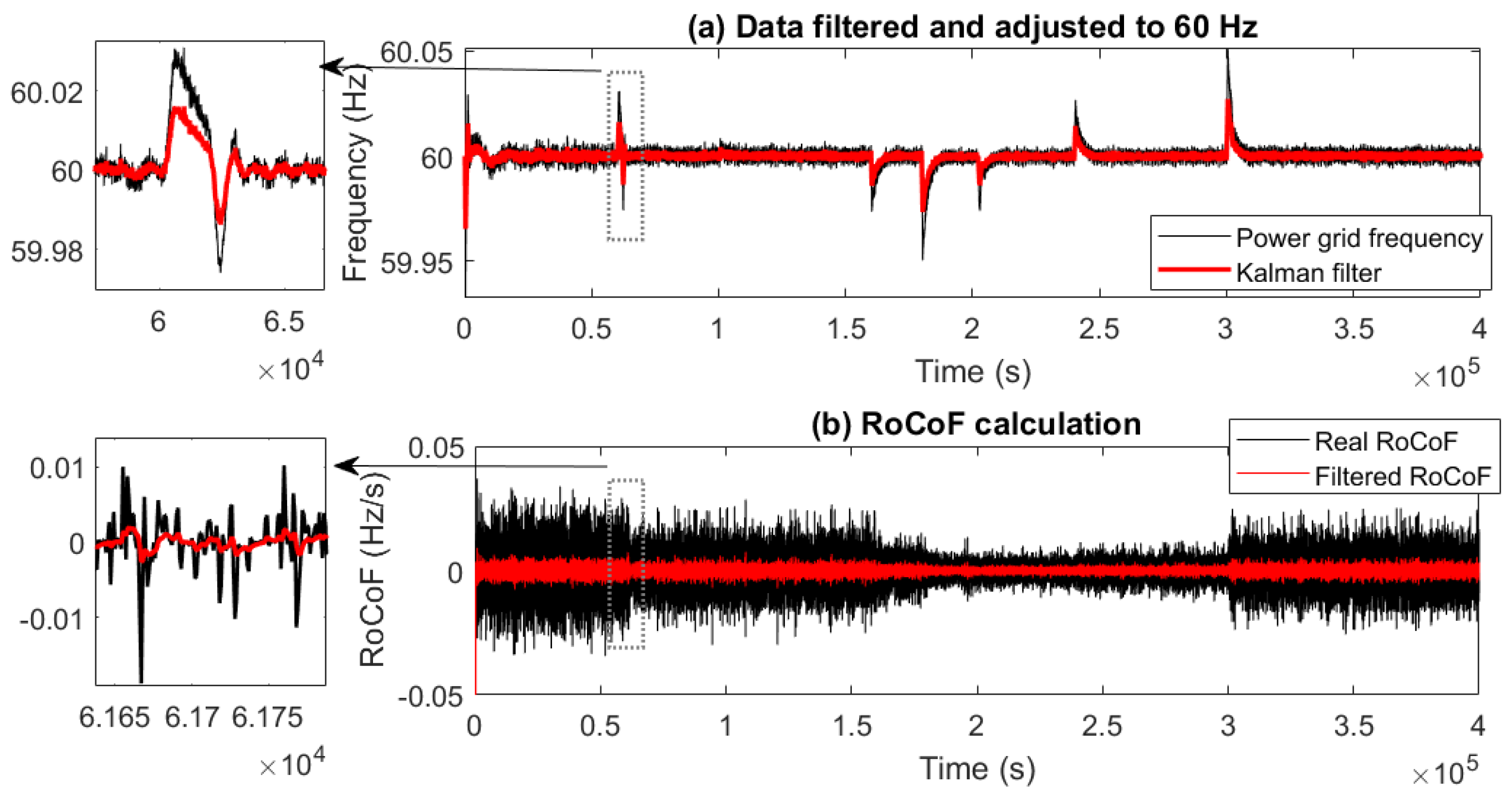
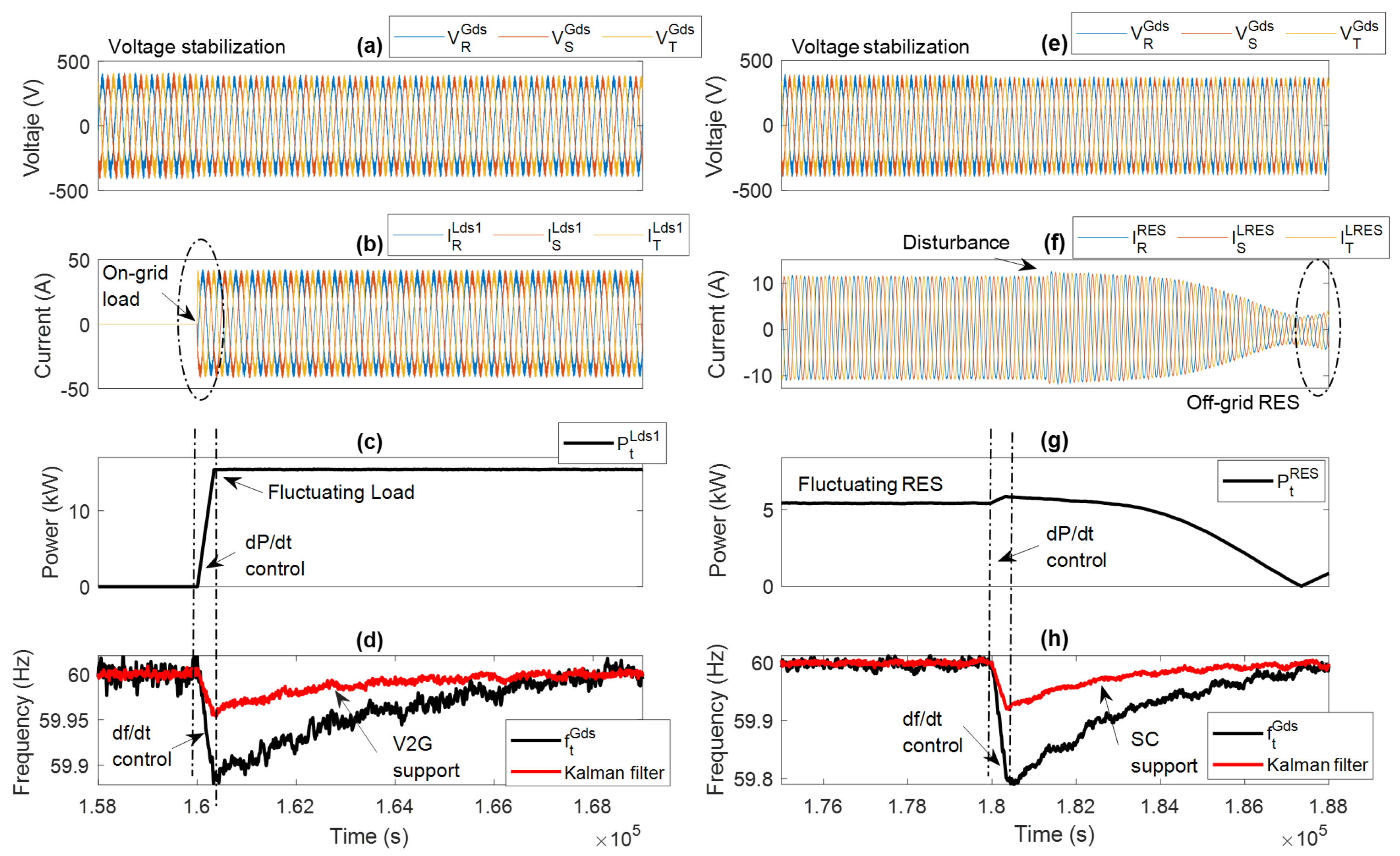
3.4. Kalman Filter-Based Support

The main objective of the Kalman filter implementation is to estimate the internal states of the power grid frequency and to predict them to enable precise real-time control. The system is modeled in discrete state-space as described in Section 3.4.
Figure 8a illustrates the effectiveness of the Kalman filter algorithm in improving power system control and stability. This approach significantly improves the dynamic response during power fluctuations, allowing the SC and EVB to efficiently compensate for fast transient d P / d t and d f / d t demands. This ensures smooth power exchange with the AC bus. Furthermore, the Kalman filter provides accurate real-time estimation of internal states, facilitating robust frequency stabilization.
Figure 8b compares the power grid frequency and Kalman-filtered RoCoF signals. The filtered signal exhibits a smoother and more stable profile, effectively reducing the impact of measurement noise and transient disturbances. This enhancement minimizes the risk of false triggering in protection schemes and improves the reliability of frequency stability assessment in low-inertia MG environments. In addition, the nominal-frequency adjustment parameters allow for balance to be maintained under power grid disturbances.
The results of the proposed power–frequency control process based on power smoothing and frequency stability with SC and V2G systems are presented below.
The joint application of the proposed control model is presented in Figure 9a–d, which shows the results of the model testing under specific conditions in a power system. Variations in PCC voltage, three-phase current R,S,T, smoothed power, and frequency are presented for two situations: the connection of a load and the application of stabilization filters. It is observed that the voltage and current in the first graphs (a) and (b) have significant fluctuations that correspond to the load connection, while the power in (c) reflects a controlled increase due to the assigned d P / d t limit. On the other hand, the frequency (d) experiences an initial drop, mitigated with V2G support and the use of a Kalman filter with d f / d t control.
On the other hand, Figure 9e–h show how the system behaves in the face of an RES disturbance. In (e) and (f), the voltage and current have more controlled variation, but the presence of a momentary disturbance stands out. The power generated by the renewable source (g) shows a gradual decrease, indicating the inherent variability in this type of energy. Finally, the frequency (h) shows a similar behavior to that in graph (d), with an initial drop mitigated by SC support and a Kalman filter. Overall, the graph shows the importance of d f / d t and d p / d t control strategies for maintaining the stability of the electrical system.

4. Discussion

To improve grid stability, control strategies and the integration of supercapacitors and EVBs for energy storage have been employed. In MGs and systems with high RES penetration, frequency control using Kalman filters and SC management strategies improves stability and reduces disturbances. These solutions enable the electrical system to respond quickly and efficiently to load fluctuations, ensuring reliable and safe operation. The application of a Kalman filter to conduct power smoothing through combined control represents a key strategy to improve frequency stability in electrical systems with high penetration of renewable energies. The Kalman filter allows for accurate estimation of the grid frequency, reducing the impact of disturbances and noise on the measurements, which facilitates a more robust response to load and generation variations. On the other hand, the rate-of-change control limits the speed of variation of the power generated by RESs, avoiding sharp fluctuations that could compromise system stability. The optimization of this process is achieved through the integration of predictive models that dynamically adjust the system response, allowing storage and compensation devices, such as SCs and EVBs, to act in a coordinated manner to mitigate the effects of variability in generation. The results displayed in Figure 9 indicate that the joint application of these techniques significantly improves frequency stability, reducing the RoCoF and minimizing the risk of disconnection of critical loads. Furthermore, the implementation of adaptive adjustments using the Kalman filter allows for greater accuracy in estimating the nominal frequency, ensuring more reliable operation of the electrical system in high-variability scenarios.

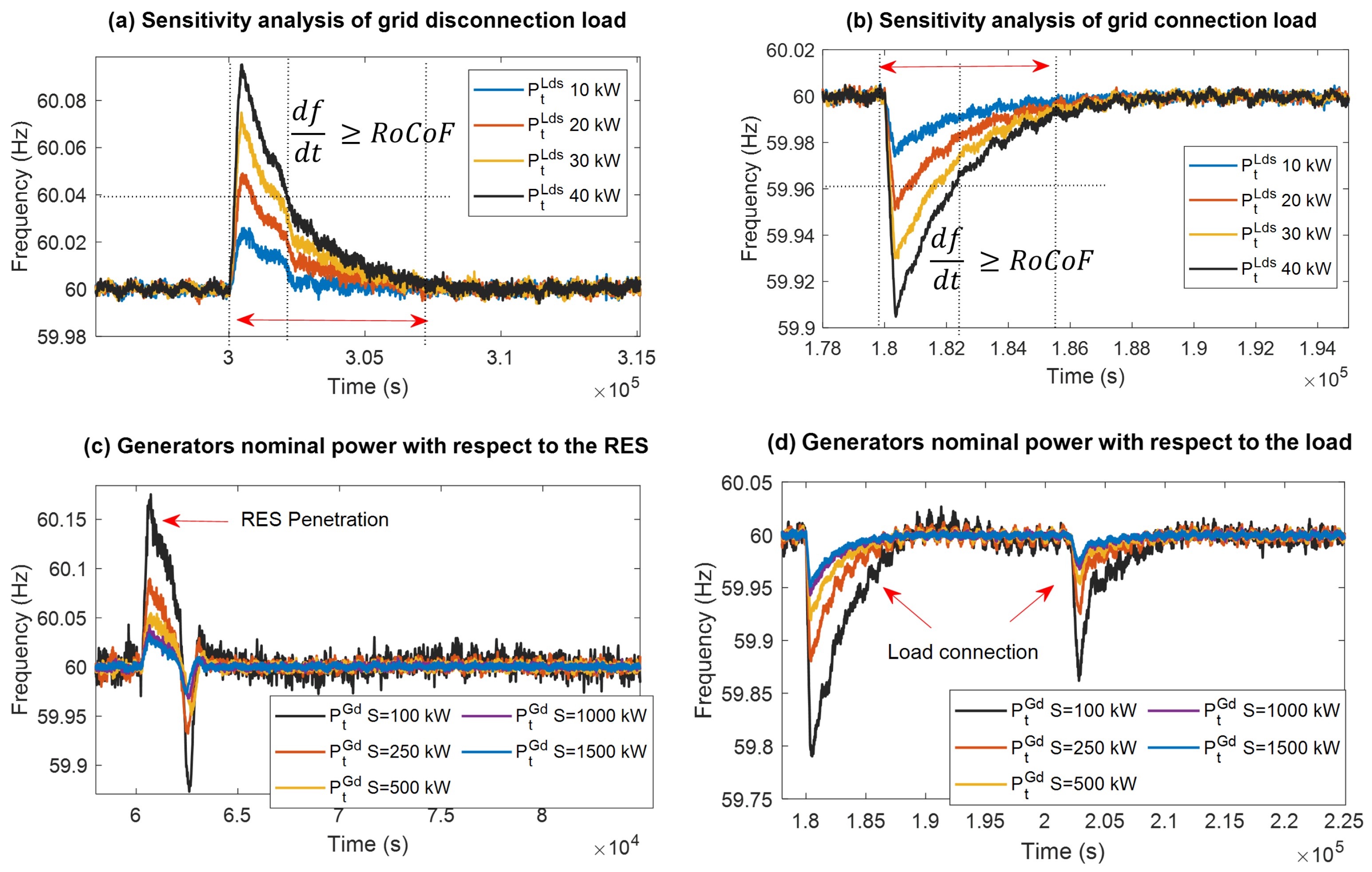
4.1. Sensitivity Analysis of System Power and Load

Figure 10a illustrates the impact of load disconnection on power balance with power ranges of 10, 20, 30, and 40 kW. When a percentage of the load is suddenly removed, the resulting excess generation leads to an increase in system frequency if not managed properly. Conversely, Figure 10b depicts the case of load connection, where the introduction of new loads increases power demand, causing a frequency drop if generation is not promptly adjusted. These scenarios highlight the system’s vulnerability to rapid load variations and the necessity for fast-response control mechanisms.
On the other hand, the impact on the nominal power of the distributed system implies less stability in a smaller grid power system, as indicated in Equation (10) with regard to S i . In this context, Figure 10c analyzes the influence of RES penetration on the nominal system power. As the RES contribution increases, the inherent variability and intermittency introduce greater power fluctuations, challenging the system’s frequency stability. Figure 10d examines the effect of varying load levels on nominal power. Higher load conditions impose additional stress on the MG, amplifying the risk of frequency deviations. These results underscore the importance of incorporating advanced energy management and storage systems to mitigate the dynamic impacts of both RES and load variability. Likewise, there is a clear need to consider systems that provide inertia to the electrical system in the face of the high penetration of renewable energy.

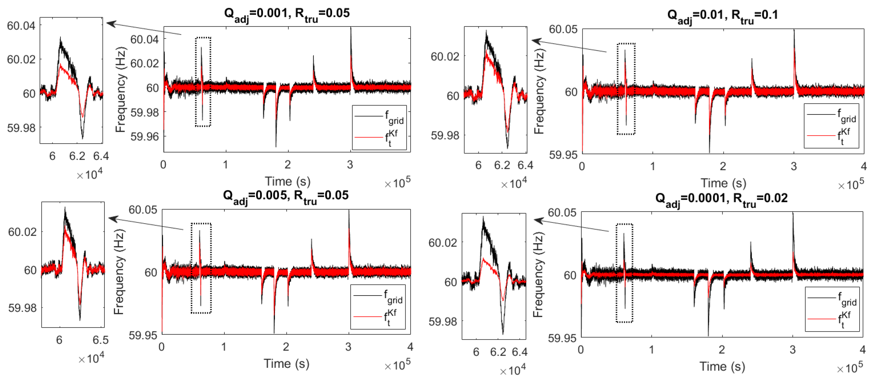
4.2. Sensitivity Analysis for Kalman Filter-Based Control

The prediction matrix, initial conditions, and fluctuation characteristics can significantly affect the accuracy and stability of the Kalman filter. Therefore, a sensitivity analysis is presented to evaluate the robustness and performance of this proposed algorithm in the presence of uncertainties or disturbances in the electrical system. Figure 11 presents the impact of a control strategy based on Kalman filtering on the variation in the initial estimation error Q a d j and the confidence adjustment coefficient R t r u of the measured data, respectively.
As can be seen, the Kalman filter responds to different tuning parameter settings. A setting of Q a j u s = 0.0001 and R t r u = 0.02 represents very limited tuning and requires a large operational capacity. However, a setting of Q a j u s = 0.005 and R t r u = 0.05 allows operation only in the event of power fluctuations, which guarantees the optimization of the process and limits the RoCoF.

5. Conclusions

This research objectively presents a combination of two strategies to control the power smoothing of renewable energy sources and frequency regulation of the electrical grid under different demand scenarios.
The hybrid combination of supercapacitors and electric-vehicle battery storage systems allows for the maintenance of system stability by mitigating fluctuations and controlling the frequency rate of change during grid disturbances.
The ability of supercapacitors to address rapid power fluctuations, combined with V2G technology, provides improved energy management and distribution grid balance with rapid demand response. This combination also effectively mitigates power grid disturbances and provides installed capacity to increase the inertia of the electrical system.
This hybrid combination offers a robust and efficient solution for achieving high levels of grid self-sufficiency and stability. Optimizing such a system requires considering short- and long-term dynamics, taking into account the characteristics of each energy storage technology and the operational constraints of the microgrid.
The integration of a Kalman filter allows for the execution of a predictive correction and adjustment vector toward the nominal frequency of 60 Hz, which improves the system’s input-frequency signal. The adjustment coefficients Q a d j u s = 0.005 and R t r u = 0.05 allow for operation within an optimal range and act only in case of power fluctuations, thus limiting the RoCoF.

Author Contributions

A.C.: Visualization, Supervision, Software, Resources, Writing—Original Draft, Writing—Review and Editing, Methodology. D.B.: Visualization, Supervision, Software, Resources, Writing—Original Draft, Writing—Review and Editing, Project administration, Methodology. P.A.: Resources, Writing—Original Draft, Methodology, Investigation, Formal analysis, Data curation, Writing—Review and Editing, Validation. L.I.M.-A.: Resources, Writing—Original Draft, Methodology, Investigation, Formal analysis, Data curation, Writing—Review and Editing, Validation. D.M.-J.: Methodology, Investigation, Funding acquisition, Formal analysis, Data curation, Conceptualization, Visualization. All authors have read and agreed to the published version of the manuscript.

Funding

This research received no external funding.

Data Availability Statement

The original contributions presented in the study are included in the article, further inquiries can be directed to the corresponding author.

Acknowledgments

This manuscript is an outcome of the Doctoral Program in Renewable Natural Resources offered by Universidad de Cuenca and Universidad del Azuay. Adrian Criollo gratefully acknowledges Universidad de Cuenca for funding his Ph.D. scholarship. Dario Benavides thanks the Dirección de Investigación y Desarrollo (DIDE) of the Universidad Técnica de Ambato for supporting this work through the research project PFISEI36, “Development of Computational Tools for the Management and Optimization of Smart Microgrids.” The authors thank the Faculty of Engineering, Universidad de Cuenca, Ecuador, for enabling access to the Microgrid Laboratory’s facilities, allowing the use of its equipment, and authorizing its staff to provide the technical support necessary to carry out the experiments described in this article. The icons used in this document were developed using Freepik, monkik, Smashicons, and Pixel perfect, available at www.flaticon.com (accessed on 10 April 2025).

Conflicts of Interest

The authors declare no conflicts of interest.

References

  1. Onishi, V.C.; Antunes, C.H.; Trovão, J.P.F. Optimal energy and reserve market management in renewable microgrid-PEVs parking lot systems: V2G, demand response and sustainability costs. Energies 2020, 13, 1884. [Google Scholar] [CrossRef]
  2. Cao, Y.; Wu, Q.; Zhang, H.; Li, C. Optimal sizing of hybrid energy storage system considering power smoothing and transient frequency regulation. Int. J. Electr. Power Energy Syst. 2022, 142, 108227. [Google Scholar] [CrossRef]
  3. Vuić, L.; Hivziefendić, J.; Sarić, M.; Osmić, J. Voltage and frequency control of solar–battery–diesel based islanded microgrid. J. Electr. Eng. 2023, 74, 442–453. [Google Scholar] [CrossRef]
  4. satya nagasri Dangeti, L.; Marimuthu, R. Distributed model predictive control strategy for microgrid frequency regulation. Energy Rep. 2025, 13, 1158–1170. [Google Scholar] [CrossRef]
  5. Herzig, M.; Paetzold, J. Feasibility study on the Rate of Change of Frequency requirements in VDE-AR-N 4120. In Proceedings of the International ETG-Congress 2019; ETG Symposium, Esslingen, Germany, 8–9 May 2019; pp. 1–6. [Google Scholar]
  6. Grebla, M.; Yellajosula, J.R.A.K.; Høidalen, H.K. Adaptive Frequency Estimation Method for ROCOF Islanding Detection Relay. IEEE Trans. Power Deliv. 2020, 35, 1867–1875. [Google Scholar] [CrossRef]
  7. Javadi, M.; Gong, Y.; Chung, C.Y. Frequency Stability Constrained BESS Sizing Model for Microgrids. IEEE Trans. Power Syst. 2024, 39, 2866–2878. [Google Scholar] [CrossRef]
  8. Jan, M.U.; Xin, A.; Rehman, H.U.; Abdelbaky, M.A.; Iqbal, S.; Aurangzeb, M. Frequency regulation of an isolated microgrid with electric vehicles and energy storage system integration using adaptive and model predictive controllers. IEEE Access 2021, 9, 14958–14970. [Google Scholar] [CrossRef]
  9. Habib, H.U.R.; Subramaniam, U.; Waqar, A.; Farhan, B.S.; Kotb, K.M.; Wang, S. Energy cost optimization of hybrid renewables based V2G microgrid considering multi objective function by using artificial bee colony optimization. IEEE Access 2020, 8, 62076–62093. [Google Scholar] [CrossRef]
  10. Kisacikoglu, M.C.; Ozpineci, B.; Tolbert, L.M. EV/PHEV bidirectional charger assessment for V2G reactive power operation. IEEE Trans. Power Electron. 2013, 28, 5717–5727. [Google Scholar] [CrossRef]
  11. Villa-Ávila, E.; Arévalo, P.; Ochoa-Correa, D.; Espinoza, J.L.; Albornoz-Vintimilla, E.; Jurado, F. Improving V2G Systems Performance with Low-Pass Filter and Fuzzy Logic for PV Power Smoothing in Weak Low-Voltage Networks. Appl. Sci. 2025, 15, 1952. [Google Scholar] [CrossRef]
  12. Srihari, G.; Krishnam Naidu, R.; Falkowski-Gilski, P.; Bidare Divakarachari, P.; Kiran Varma Penmatsa, R. Integration of electric vehicle into smart grid: A meta heuristic algorithm for energy management between V2G and G2V. Front. Energy Res. 2024, 12, 1357863. [Google Scholar] [CrossRef]
  13. Zhang, C.; Kitamura, H.; Goto, M. Feasibility of vehicle-to-grid (V2G) implementation in Japan: A regional analysis of the electricity supply and demand adjustment market. Energy 2024, 311, 133317. [Google Scholar] [CrossRef]
  14. Janardhan, G.; Shanmugasundaram, R.; Narendar, R.; Kumar K, S. Modeling and Simulation of Vehicle to Grid (V2G) Integration. In Proceedings of the E3S Web of Conferences; EDP Sciences: Paris, France, 2025; Volume 616, p. 01016. [Google Scholar]
  15. Ellis, B.E.; Pearre, N.; Swan, L. Impact of residential photovoltaic systems on net load intermittency. Renew. Energy Focus 2023, 46, 377–384. [Google Scholar] [CrossRef]
  16. Jiang, H.; Lu, N.; Yao, L.; Qin, J.; Liu, T. Impact of climate changes on the stability of solar energy: Evidence from observations and reanalysis. Renew. Energy 2023, 208, 726–736. [Google Scholar] [CrossRef]
  17. Zhu, H.; Li, H.; Liu, G.; Ge, Y.; Shi, J.; Li, H.; Zhang, N. Energy Storage in High Variable Renewable Energy Penetration Power Systems: Technologies and Applications. CSEE J. Power Energy Syst. 2023, 9, 2099–2108. [Google Scholar] [CrossRef]
  18. Imtiaz, S.; Yang, L.; Munir, H.M.; Memon, Z.A.; Kilic, H.; Naz, M.N. DC-link voltage stability enhancement in intermittent microgrids using coordinated reserve energy management strategy. IET Renew. Power Gener. 2025, 19, e13197. [Google Scholar] [CrossRef]
  19. Frasetyo, M.B.; Wijaya, F.D.; Ali, H.R. Islanded Wind Farm Microgrid Stability Control using Synchronverter Algorithm. IEEJ J. Ind. Appl. 2023, 12, 603–612. [Google Scholar] [CrossRef]
  20. Wu, Z.H.; Yu, Y.X. Regulating the Electrochemical Performance of A2Ni2TeO6 (A = Na, K) as a Cathode of Alkali Metal Ion Battery by 3d Transition Metal Substitution from a Theoretical Perspective. ACS Appl. Energy Mater. 2024, 7, 8715–8725. [Google Scholar] [CrossRef]
  21. Cougnon, C. Impact of the Scan Rate on the Stability Window of an Electrical Double-Layer Capacitor. Energies 2023, 16, 5687. [Google Scholar] [CrossRef]
  22. Zeeshan, T.; Tahir, E.; Waseem, S.; Ali, M.D.; Anjum, S. Nickel substituted cobalt ferrites via ceramic rout approach: Exploration of structural, optical, dielectric and electrochemical behavior for pseudo-capacitors. Ceram. Int. 2025, 51, 5808–5820. [Google Scholar] [CrossRef]
  23. Shi, C.; Wang, Y.; Kulaots, I.; Zhu, H.; Sheldon, B. Water-in-Salt Battery Electrolyte for High-Voltage Supercapacitors: A Fundamental Study on Biomass and Carbon Fiber Electrodes. J. Electrochem. Soc. 2024, 171, 110526. [Google Scholar] [CrossRef]
  24. Subasinghage, K.; Gunawardane, K.; Padmawansa, N.; Kularatna, N.; Moradian, M. Modern supercapacitors technologies and their applicability in mature electrical engineering applications. Energies 2022, 15, 7752. [Google Scholar] [CrossRef]
  25. Navarro, G.; Torres, J.; Blanco, M.; Nájera, J.; Santos-Herran, M.; Lafoz, M. Present and future of supercapacitor technology applied to powertrains, renewable generation and grid connection applications. Energies 2021, 14, 3060. [Google Scholar] [CrossRef]
  26. Fang, Z.; Shek, J.K.; Sun, W. A review of grid-connected hybrid energy storage systems: Sizing configurations, control strategies, and future directions. J. Energy Storage 2025, 118, 116226. [Google Scholar] [CrossRef]
  27. Luo, X.; Barreras, J.V.; Chambon, C.L.; Wu, B.; Batzelis, E. Hybridizing lead–acid batteries with supercapacitors: A methodology. Energies 2021, 14, 507. [Google Scholar] [CrossRef]
  28. Vasantharaj, S.; Indragandhi, V.; Subramaniyaswamy, V.; Teekaraman, Y.; Kuppusamy, R.; Nikolovski, S. Efficient control of dc microgrid with hybrid pv—fuel cell and energy storage systems. Energies 2021, 14, 3234. [Google Scholar] [CrossRef]
  29. Wu, X.; Wu, Y.; Tang, Z.; Kerekes, T. An adaptive power smoothing approach based on artificial potential field for PV plant with hybrid energy storage system. Sol. Energy 2024, 270, 112377. [Google Scholar] [CrossRef]
  30. Abadi, S.A.G.K.; Habibi, S.I.; Khalili, T.; Bidram, A. A model predictive control strategy for performance improvement of hybrid energy storage systems in DC microgrids. IEEE Access 2022, 10, 25400–25421. [Google Scholar] [CrossRef]
  31. Rajnarayanan, P.; Kathiravan, K. Supercapacitors as distributed energy storage systems for EV charging infrastructure. In Distributed Energy Storage Systems for Digital Power Systems; Elsevier: Amsterdam, The Netherlands, 2025; pp. 149–166. [Google Scholar]
  32. Lu, Q.; Yang, Y.; Chen, J.; Liu, Y.; Liu, N.; Cao, F. Capacity optimization of hybrid energy storage systems for offshore wind power volatility smoothing. Energy Rep. 2023, 9, 575–583. [Google Scholar] [CrossRef]
  33. Rimal, B.P.; Kong, C.; Poudel, B.; Wang, Y.; Shahi, P. Smart electric vehicle charging in the era of internet of vehicles, emerging trends, and open issues. Energies 2022, 15, 1908. [Google Scholar] [CrossRef]
  34. Shaker, Y.O.; Yousri, D.; Osama, A.; Al-Gindy, A.; Tag-Eldin, E.; Allam, D. Optimal charging/discharging decision of energy storage community in grid-connected microgrid using multi-objective hunger game search optimizer. IEEE Access 2021, 9, 120774–120794. [Google Scholar] [CrossRef]
  35. Suresh, V.; Janik, P.; Guerrero, J.M.; Leonowicz, Z.; Sikorski, T. Microgrid energy management system with embedded deep learning forecaster and combined optimizer. IEEE Access 2020, 8, 202225–202239. [Google Scholar] [CrossRef]
  36. Lazaroiu, G.C.; Roscia, M. Fuzzy logic strategy for priority control of electric vehicle charging. IEEE Trans. Intell. Transp. Syst. 2022, 23, 19236–19245. [Google Scholar] [CrossRef]
  37. Benavides, D.; Arévalo, P.; Villa-Ávila, E.; Aguado, J.A.; Jurado, F. Predictive power fluctuation mitigation in grid-connected PV systems with rapid response to EV charging stations. J. Energy Storage 2024, 86, 111230. [Google Scholar] [CrossRef]
  38. Li, G.; Yang, Z.; Li, B.; Bi, H. Power allocation smoothing strategy for hybrid energy storage system based on Markov decision process. Appl. Energy 2019, 241, 152–163. [Google Scholar] [CrossRef]
  39. Benavides, D.; Arévalo, P.; Tostado-Véliz, M.; Vera, D.; Escamez, A.; Aguado, J.A.; Jurado, F. An Experimental Study of Power Smoothing Methods to Reduce Renewable Sources Fluctuations Using Supercapacitors and Lithium-Ion Batteries. Batteries 2022, 8, 228. [Google Scholar] [CrossRef]
  40. Zar, A.; Rehman, H.; Ahmad, I. Neural network based optimized barrier conditioned double super-twisting sliding mode controller of electric vehicle charger with grid to vehicle and vehicle to grid modes. J. Energy Storage 2023, 74, 109234. [Google Scholar] [CrossRef]
  41. Benavides, D.; Arévalo, P.; Criollo, A.; Tostado-Véliz, M.; Jurado, F. Multi-mode monitoring and energy management for photovoltaic-storage systems. Renew. Energy 2024, 230, 120820. [Google Scholar] [CrossRef]
  42. Review of PREPA Technical Requirements for Interconnecting Wind and Solar Generation | Search Results | IUCAT South Bend. Available online: https://docs.nrel.gov/docs/fy14osti/57089.pdf (accessed on 11 June 2025).
  43. Lamsal, D.; Sreeram, V.; Mishra, Y.; Kumar, D. Output power smoothing control approaches for wind and photovoltaic generation systems: A review. Renew. Sustain. Energy Rev. 2019, 113, 109245. [Google Scholar] [CrossRef]
  44. Mao, M.; Tang, Y.; Chen, J.; Ma, F.; Li, Z.; Ma, H.; Sun, H.; Yin, C.; Li, H. An Overview of Solar Photovoltaic Power Smoothing Control Strategies Based on Energy Storage Technology. Energies 2025, 18, 909. [Google Scholar] [CrossRef]
  45. Marcos, J.; Storkël, O.; Marroyo, L.; Garcia, M.; Lorenzo, E. Storage requirements for PV power ramp-rate control. Sol. Energy 2014, 99, 28–35. [Google Scholar] [CrossRef]
  46. Bašakarad, T.; Holjevac, N.; Kuzle, I.; ivanković, I.; Zovko, N. ROCOF importance in electric power systems with high renewables share: A simulation case for croatia. In Proceedings of the 12th Mediterranean Conference on Power Generation, Transmission, Distribution and Energy Conversion (MEDPOWER 2020), Virtual, 9–12 November 2020; Volume 2020, pp. 72–77. [Google Scholar] [CrossRef]
  47. Benavides, D.; Villa-Ávila, E.; Criollo, A.; Aguado, J.A. Optimal energy management of energy storage and electric vehicles in power systems. In Towards Future Smart Power Systems with High Penetration of Renewables; Elsevier: Amsterdam, The Netherlands, 2025; pp. 413–434. [Google Scholar]
  48. Han, J.; Zhou, X.; Lu, S.; Zhao, P. A Three-Phase Bidirectional Grid-Connected AC/DC Converter for V2G Applications. J. Control Sci. Eng. 2020, 2020, 8844073. [Google Scholar] [CrossRef]
  49. Espinoza, J.L.; González, L.G.; Sempértegui, R. Micro grid laboratory as a tool for research on non-conventional energy sources in Ecuador. In Proceedings of the 2017 IEEE International Autumn Meeting on Power, Electronics and Computing (ROPEC), Ixtapa, Mexico, 8–10 November 2017; pp. 1–7. [Google Scholar] [CrossRef]
Figure 1. A schematic representation of the MG with SC and V2G support.
Batteries 11 00231 g001
Figure 2. Power smoothing for PV and WT systems: (a) Control diagram, (b) Smoothed output signal.
Batteries 11 00231 g002
Figure 3. Flowchart of the power-frequency control process with SC and V2G support.
Batteries 11 00231 g003
Figure 4. Case study of microgrid laboratory.
Batteries 11 00231 g004
Figure 5. Dynamic system evaluation: (a) Renewable generation, (b) Energy consumption loads and (c) Grid frequency response.
Batteries 11 00231 g005
Figure 6. Power–frequency variability analysis under different MG disturbance scenarios.
Batteries 11 00231 g006
Figure 7. P-f linear estimation: (a) positive ramp, (b) negative ramp.
Batteries 11 00231 g007
Figure 8. P-f linearity: (a) Kalman filter-based SC support, (b) RoCoF real and filtered data.
Batteries 11 00231 g008
Figure 9. Frequency stability optimization in MG with storage and control support: (a) Voltage stabilization in load connection, (b) Current in load connection, (c) Load power fluctuation, (d) frequency with V2G support, (e) Voltage stabilization in RES fluctuation, (f) Current disturbances in RES, (g) RES power fluctuation, (h) Frequency with V2G support.
Batteries 11 00231 g009
Figure 10. Sensitivity analysis: (a) grid load disconnection, (b) grid load connection, (c) impact of RES on nominal power of system, and (d) impact of load on nominal power of system.
Batteries 11 00231 g010
Figure 11. Sensitivity analysis for impact of Kalman filter-based control on variation in coefficients Q a d j and R t r u .
Batteries 11 00231 g011
Table 1. Summary of studies related to this field of research.
Power Smoothing TechniquesRate of Change of Frequency ControlEnergy Demand AnalysisVehicle-to-Grid SupportSupercapacitorsExperimental ValidationReferences
[2]
[29,37]
[11]
[26,30,38]
[39]
[31,40]
[32,41]
This study
Table 2. Microgrid case study equipment description.
SymbolDescriptionModelNominal PowerEnergy/DayMax. VoltagePower Converter
P t P V 1 PV System 1ATERSA A-250P15 kW≈50 kWh553 Vdc / 230 VacDC/AC
P t P V 2 PV System 2ATERSA A-250M15 kW≈50 kWh563 Vdc / 230 VacDC/AC
P t P V 3 PV System 3ATERSA A-250P5 kW≈20 kWh598 Vdc / 230 VacDC/AC
P t W T 1 WT System 1ATERSA A-250P5 kW≈30 kWh230 Vac-
P t W T 2 WT System 2enair5 kW≈30 kWh230 Vac-
P t E V B Lithium batterySamsung ELPT39250 kW44 kWh642 Vdc / 230 VacDC/AC-AC/DC
P t S C SupercapacitorsMaxwell BMOD-013050 kW0.4 kWh560 Vdc / 230 VacDC/AC-AC/DC
Table 3. Summary of studies related to this research.
EventParameter P t , f t P t + 1 , f t + 1 Δ P t , Δ f t
1Power (kW)3.4410.81−7.37
Frequency (Hz)60.001560.0305−0.029
2Power (kW)10.325.574.75
Frequency (Hz)60.004259.970.0342
3Power (kW)r5.810.76−4.96
Frequency (Hz)60.000259.95090.0493
4Power (kW)11.1917.31−6.12
Frequency (Hz)6059.97250.0276
5Power (kW)16.8811.265.62
Frequency (Hz)60.001160.0264−0.0253
6Power (kW)11.274.586.69
Frequency (Hz)59.999260.0483−0.0491
Disclaimer/Publisher’s Note: The statements, opinions and data contained in all publications are solely those of the individual author(s) and contributor(s) and not of MDPI and/or the editor(s). MDPI and/or the editor(s) disclaim responsibility for any injury to people or property resulting from any ideas, methods, instructions or products referred to in the content.

