Article

Safety-Critical Influence of Ageing on Mechanical Properties of Lithium-Ion Pouch Cells

1
Vehicle Safety Institute, Graz University of Technology, Inffeldgasse 13/VI, 8010 Graz, Austria
2
Dr. Ing. h.c. F. Porsche AG, Porscheplatz 1, 70435 Stuttgart, Germany
3
ZwickRoell GmbH & Co. KG, August-Nagel-Str. 11, 89079 Ulm, Germany
*
Author to whom correspondence should be addressed.
Batteries 2025, 11(3), 99; https://doi.org/10.3390/batteries11030099
Submission received: 29 January 2025 / Revised: 25 February 2025 / Accepted: 2 March 2025 / Published: 7 March 2025
(This article belongs to the Special Issue Batteries Aging Mechanisms and Diagnosis)

Abstract

:
While the effect of ageing has been thoroughly analysed, to improve the cycle life of lithium-ion batteries, its impact on safety in case of a mechanical loading is still a new field of research. It has to be found out how mechanical properties, such as the tolerable failure force or deformation, change over the operational lifetime of a battery. To answer this question, mechanical abuse tests were carried out with pouch cells used in recent electric vehicles in a fresh state and after usage over 160.000 km. These tests were complemented with a detailed component level analysis, in order to identify mechanisms that lead to changed cell behaviour. For the analysed aged cells, a significantly different mechanical response was observed in comparison with the respective fresh samples. The tolerable force was severely reduced (up to −27%), accompanied by a notable reduction in the allowable deformation level (up to −15%) prior to failure, making the aged cells clearly more safety critical. Based on the subsequent component tests, the predominant mechanism for this different behaviour was concluded to be particle cracking in the cathode active material. The found results are partly in contrast with the (few) other already published works. It is, however, unclear if this difference is rooted in different cell chemistries or types, or another battery state resulting from varying ageing procedures. This underlies the importance of further investigations in this research field to close the apparent gap of knowledge.

1. Introduction

An increase in mobility electrification is considered to be one pillar of the global effort to reduce the consumption of fossil energy sources [1]. For further proliferation of the latter, the safety of the electric energy storage system (EES) in case of an accident is one crucial factor. Consequently, additional crash tests [2] and assessment criteria [3] were already introduced to address new challenges arising from this important field of research and development.
Currently, factory-new cars with pristine EESs are used for homologation and consumer crash tests. Recent studies, however, report that the mechanical properties of lithium-ion batteries (LIBs) are subject to change over their operational life, as a result of progressing ageing or degradation mechanisms, even under “normal” application conditions. This raises the question of whether an aged electric vehicle (EV) is still safe in case of an accident after having been used over a certain duration.
Generally, the ageing of LIBs can be categorised into the two main degradation modes, namely the loss of lithium inventory (LLI) and loss of active material (LAM) [4,5], both resulting in an irreversible performance loss. The mechanisms leading to the above mentioned degradation modes are electrolyte decomposition, solid electrolyte interface (SEI) growth, current collector corrosion, active material particle cracking and delamination [4,5,6,7,8], whereby active material coating degradation and delamination [9,10,11,12,13,14,15], cathode particle cracking [16,17,18,19], current collector degradation [20,21], separator degradation [22,23,24,25] and binder degradation [4,5,6,26] are considered to be most critical regarding safety and mechanical properties [5].
While already a notable number of studies were already published on the mechanical characterisation of LIBs, mainly for the purpose of the calibration of simulation models [27,28,29], only few research has been published with scope on the influence of ageing on the latter. A small number of papers are also available focusing on the influence of ageing on other safety-relevant properties, such as the process of thermal runaway and short circuit [30,31] or thermal conductivity [32,33,34].
Sprenger et al. [35,36] conducted cylindrical indentation studies on C/NMC (Graphite anode, Nickel-Manganese-Cobalt cathode) pouch cells with a nominal capacity of 74 Ah, artificially aged and replicating a real driving profile to a state of health (SOH) of 90% at a temperature ranging from −3 °C to 30 °C. They found that at a state of charge (SOC) of 100%, there is no significant difference in the failure force for fresh and aged cells, whereas the force–displacement (f-s) curve has shifted towards the right, which can be attributed to the anisotropic behaviour of cell components in addition to the SEI thickness increase. At an SOC of 0%, the failure force has significantly decreased for the artificially aged cells with a non-significant right shift of the f-s curve compared to a SOC of 100%. Lou et al. [37] used C/NMC 17 Ah pouch cells to perform spherical indentation tests. They reported an increase in failure force and displacement with an increase in the SOC level. There was no notable change in the mechanical behaviour before cell failure in this study. Liu et al. [38] conducted spherical indentation tests at SOC 25% on C/NMC 25 Ah pouch cells, which were artificially aged to an SOC of 90%, 80% and 70% at 0 °C. A right shift in the f-s curve was reported with a decrease in the SOH, whereas the failure force remained comparable. Kovachev et al. [39] conducted quasi-static cylindrical indentation tests at an SOC of 100% using 41 Ah C/NMC-LMO (Graphite anode, Nickel-Manganese-Cobalt/Lithium ion Manganese oxide blend cathode) pouch cells, artificially aged for 700 cycles. The result was an increase in failure force after ageing and a right shift in the f-s curve. They attributed this behaviour to an SEI thickness increase and cell drying out.
Overall, still only few studies deal with the impact of ageing of the mechanical properties of LIBs, and the different chosen approaches and findings indicate a significant lack of knowledge. In particular, there is still no information about which cell components are mostly influenced by ageing and which contribute most to the different failure behaviour. In addition, the majority of the studies are carried out using artificially aged cells that either replicate a specific drive cycle or a generic cycling profile. Thereby, widely no proof is delivered that the found degradation in the cells is in line with real-life application. It is considered to be of great importance to investigate the mechanical properties of LIBs after they have been used in real-life application. This study is focused on the investigation of real-life aged cells; these cells are extracted out of a car used on real-world roads. Other aspects, that are not yet or only poorly addressed in published research, are the influence of different cell chemistries on the mechanical degradation and the overall correlation of performance loss and mechanical degradation.
This present study aims to address the above-mentioned points in order to contribute to the closing of the outlined gap in knowledge.

2. Materials and Methods

2.1. Device Under Tests

In this study, LIB pouch cells with a nominal capacity of 64.6 Ah at a size of 354 × 101 × 11.4 mm were analysed. Each cell comprises 33 anode layers (Graphite + SiOx, thickness 166 µm) and 32 cathode layers (Nickel-Manganese-Cobalt 712, thickness 142 µm), which are separated by an Al-Oxide-coated single layer separator (Polypropylene, thickness 14 µm). This cell type serves as a base component of the EES in several recent electric vehicles.
In this study, fresh as well as aged cells are analysed and compared in their properties, whereby the aged cells stem from the battery of a test car that was subjected to representative consecutive drive cycles on a test track. A total distance of approx. 160.000 km and a related duration of approx. 2500 h resulted in a loss of capacity of −7%, accompanied by an increase in cell thickness by approximately 3%. After usage, the battery system (containing 38 modules in series connection, each with 12 cells in a 2P6S configuration) was removed from the test car, modules were extracted and out of these modules, cells were randomly selected for the measurement. Figure 1a shows the overlay of charge and discharge curves for fresh and aged cells, whereby an earlier cell polarisation can be observed for charging along with an earlier voltage drop during the discharge of the aged cell, both indicating advanced cell degradation. Those measurements were carried out using a programmable electrical sink/source (EA-PSB 9000).
In Figure 1b, the reversible (referred to as breathing—BrAged and BrFresh) as well as the irreversible (referred to as swelling—Sw) thickness increase in the cells during lifetime (measures obtained using a vernier caliper) can be observed. In addition to the irreversible thickness—an increase in Sw of approximately 3% at a discharged state—also a clear reduction (−33%) in the reversible thickness change Br of the cell for different states of charge is seen. The observed swelling of the aged cells is less in comparison with the literature, where a swelling of 6.3% [35] and 6.7% [39] was reported. However, taking into account the still high residual capacity of about 93% for the analysed cells in contrast to other studies, the found swelling is still considered to be in line with the literature.

2.2. Mechanical Cell Abuse Test

To analyse the influence of ageing on the mechanical properties of the cells, the latter were subjected to mechanical indentation tests that aim to represent an abusive deformation of the battery in the case of an accident. Similar or same setups were already used in other studies [35,39], which enables a direct comparison of the mechanical response of different and differently aged cells in such loading.
In Figure 2, the used test setup, as realised with the Presto Test rig (Hydraulic Press with 420 kN; described in detail in [39]) at the Battery Safety Center Graz, is shown as follows: The cells were placed on a flat, electrically insulating plate to prevent any short circuit over the test machine. A cylindrical impactor (diameter 30 mm) with a length of 70 mm and rounded edges (R = 5 mm) was pushed into the cell at its geometric center point, perpendicular to the cell stack layup and with an intrusion speed of 1 mm/min. For achieving a good comparability of the data despite the slightly varying cell thicknesses, the contact point was set, when an impactor force of 500 N was exceeded.
During the indentation, the displacement of the impactor was measured with a resolution of 1 µm [39], and the impactor force was captured using a load cell (GMT Serie K 500 kN). In addition, the cell voltage was monitored (NI-9229 voltage input module) as well as the temperatures on selected locations on the cell surface and tabs (Typ K Thermocouples). The data acquisition was carried out using an NI 9237 Module with 50 kS/s and a 24-bit resolution.
For each cell state (fresh vs. aged cell + fully charged vs. discharged to lower cell voltage limit), three repetitions were conducted. These tests delivered force–deflection curves for the different cell states as a basis for the derivation of changes in the relevant mechanical parameters of compression stiffness, failure force and displacement.

2.3. Post-Mortem Analysis of Cells

As a next step, the reasons for the observed different behaviour on a cell level were investigated in a range of further detailed studies on the cell component level. The aim was to identify the mainly involved battery component and respective degradation mechanism. For those tests, cells were discharged at a SOC of 0% for safety reasons, opened, and several anode, cathode and separator layers were extracted for sample generation.

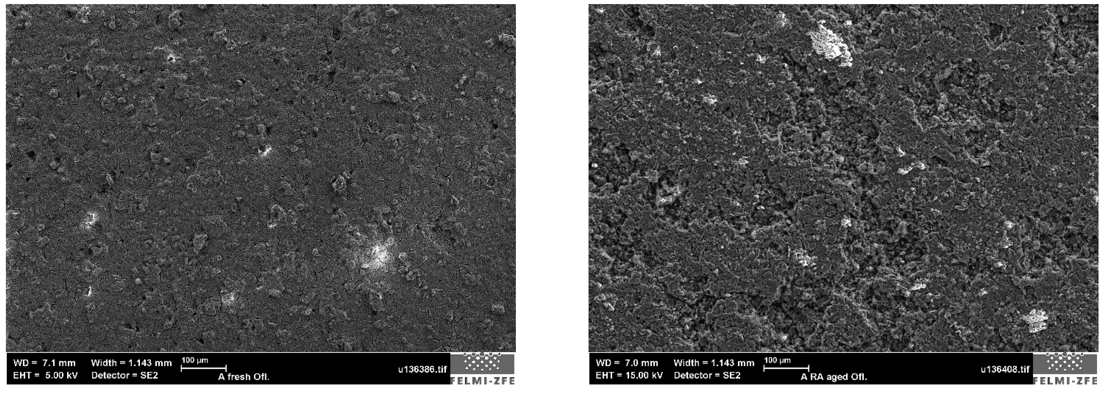
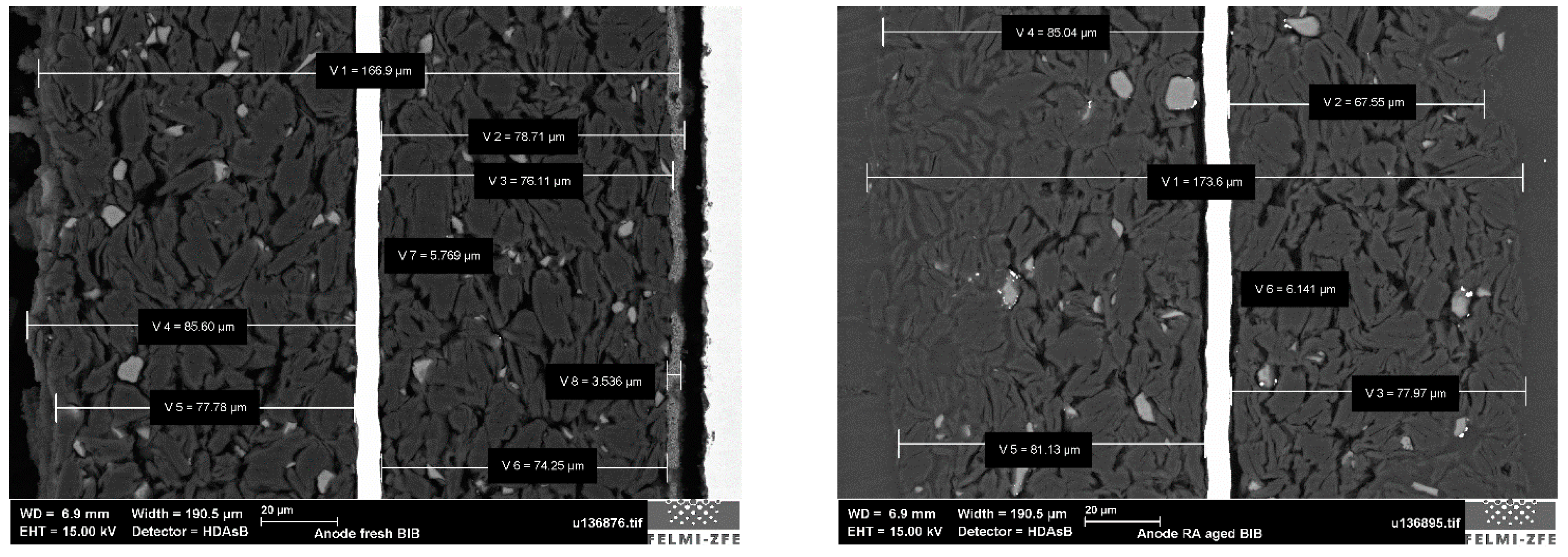
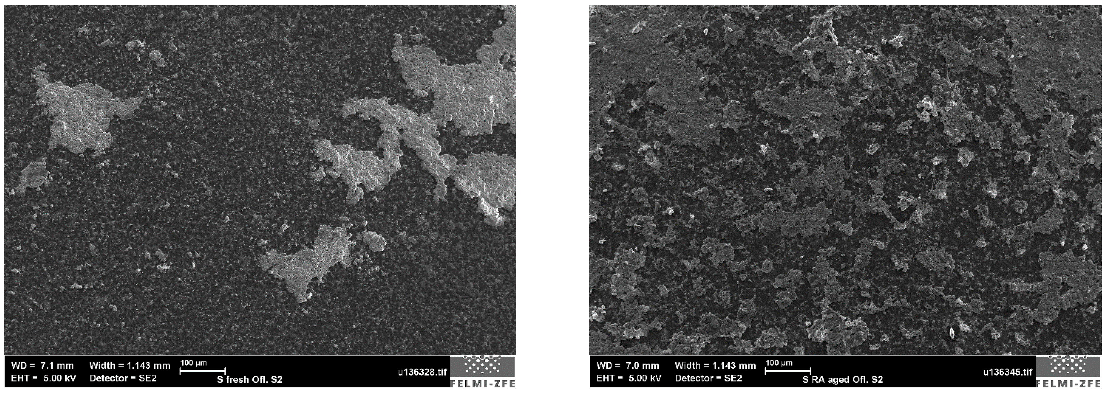
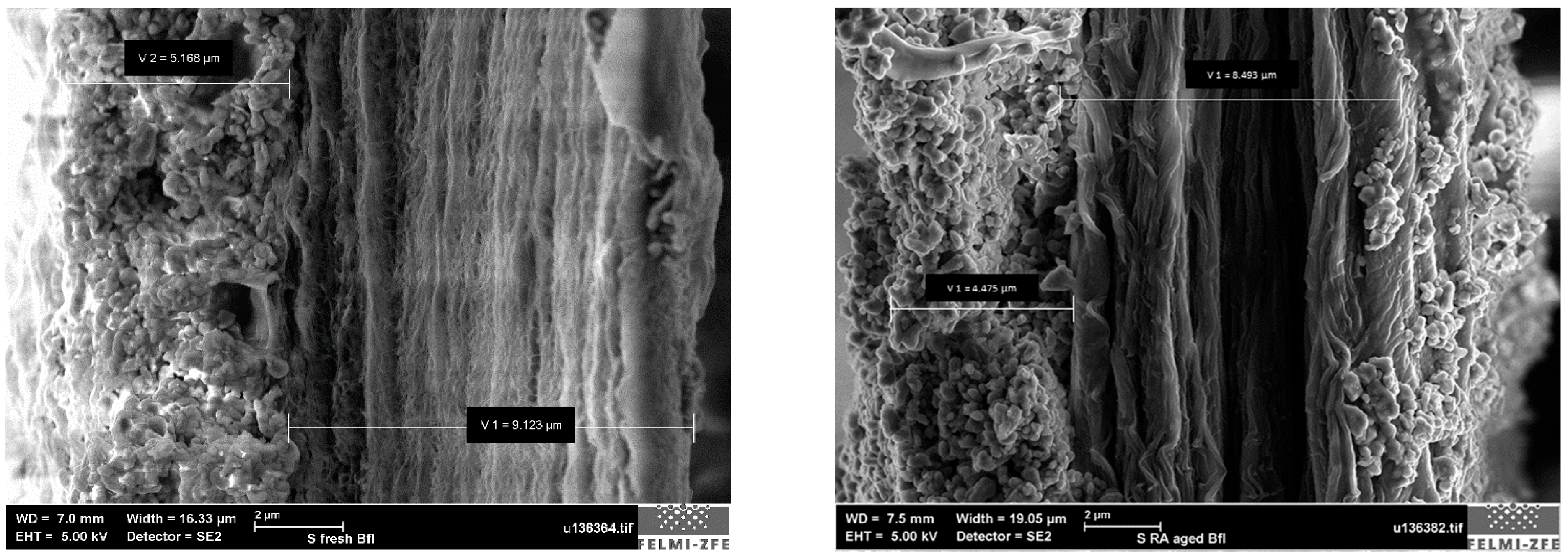
2.3.1. Microscopic Imaging of Cell Components (Surface, Cross-Section) F vs. RA

In order to identify the effect and mode of degradation of the single battery components, superficial and cross-section microscopic images were taken of either fresh and aged cells. For the cross-section images of the single layers, broad-ion beam cutting was applied in order to achieve a high quality surface finish of the section cut, as already shown in [40]. The analysis was carried out at different levels of magnification using a Zeiss Ultra 55 field emission scanning electron microscope (FESEM) at “FELMI, TU Graz”, enhanced with an EDAX Super Octane energy-dispersive x-ray spectroscopy (EDX) for elemental mapping.

2.3.2. Mechanical Characterisation of Cell Components
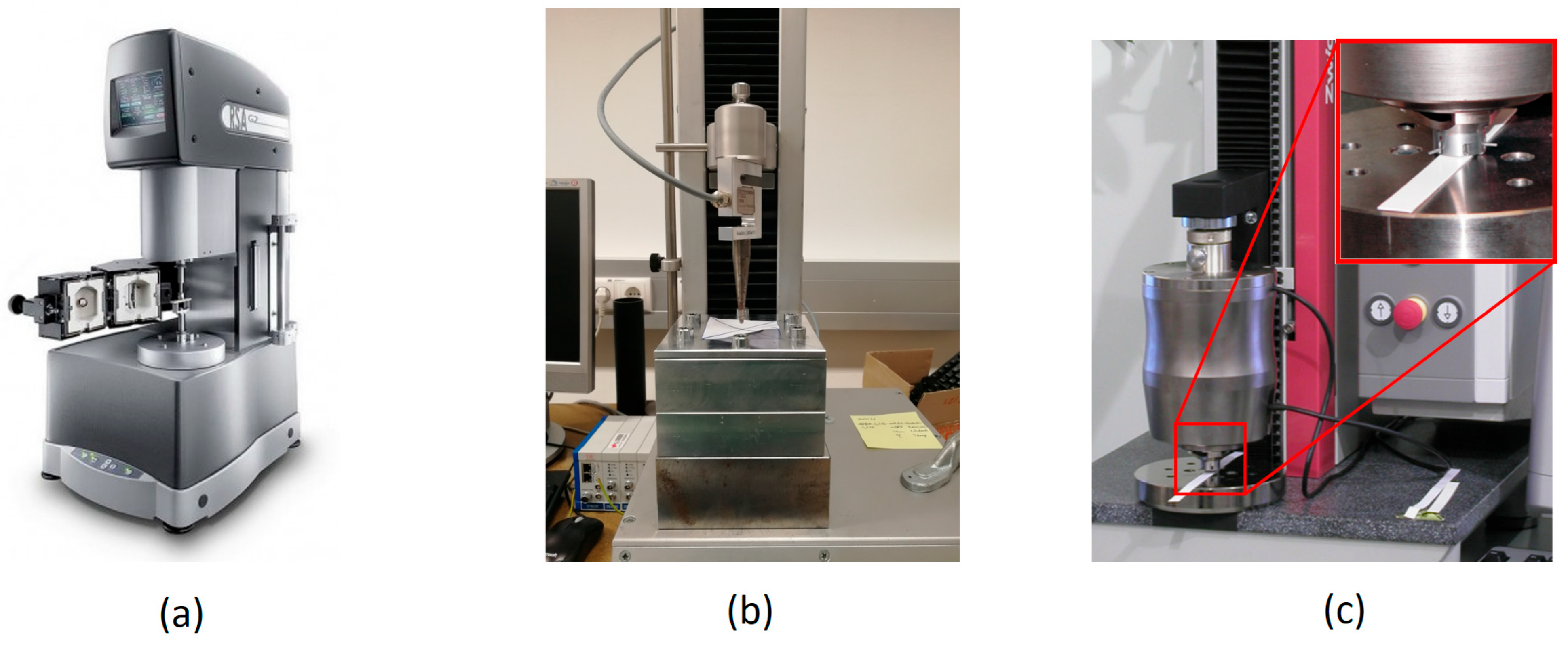
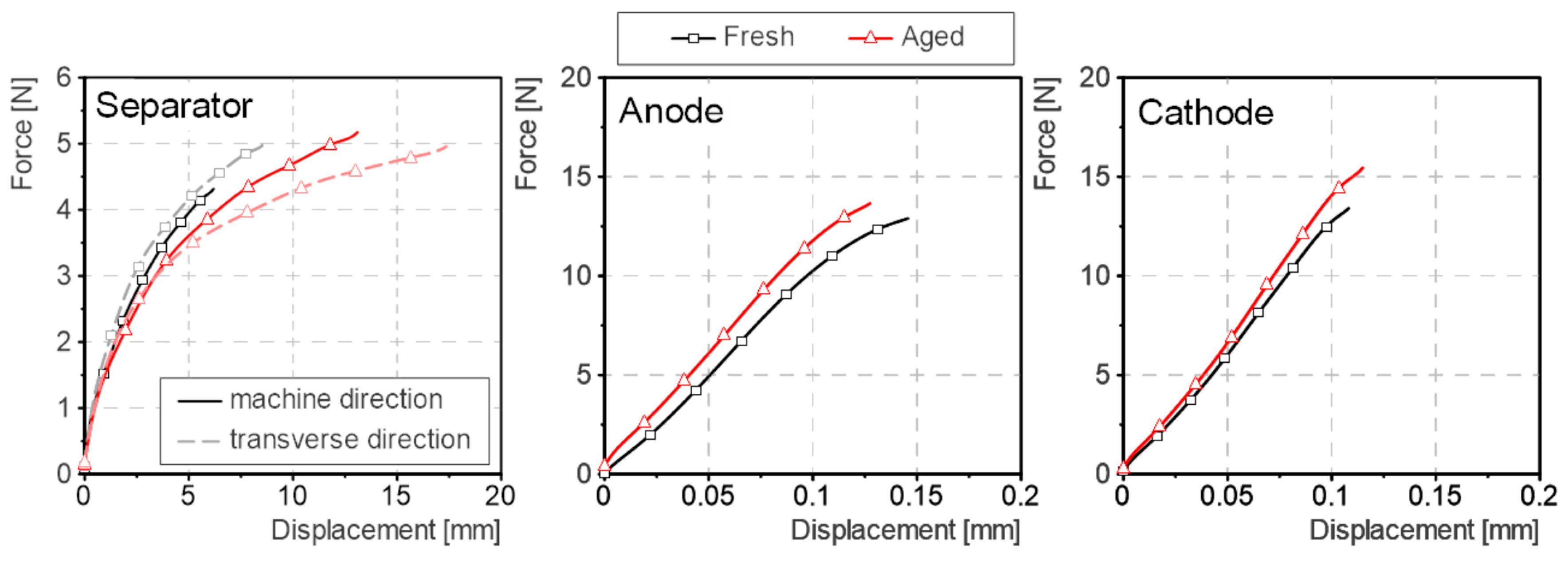
In order to capture the potentially different behaviours of the aged battery components, experiments in various loading conditions were carried out. These loading conditions are expected to be predominant in the cell layup during the cell tests: compression and bi-axial tension in the area under the impactor; and tension loads in the proximity of the impactor [41].
  • Uni-axial tensile tests:
    Tensile tests were conducted to identify possible degradation (e.g., corrosion, cracking [17,21,42]) in the current collectors of the electrodes as well as the properties of the separator. Stripes with a width of 5 mm were cut out of the single components and stored in a replacement electrolyte (dimethyl carbonate DMC). For the separator, samples were created in machine and transverse direction to take into account possible anisotropic behaviour. The samples were clamped with a free length of 15 mm (based on [43]), tested with a speed of 20 mm/min and for each component, five samples were tested. For these tests, a dynamic mechanic analyser (DMA) RSA-G2 (Figure 3a) was used. As results, single force over deflection curves of the five test repetitions as well as respective average data were obtained.
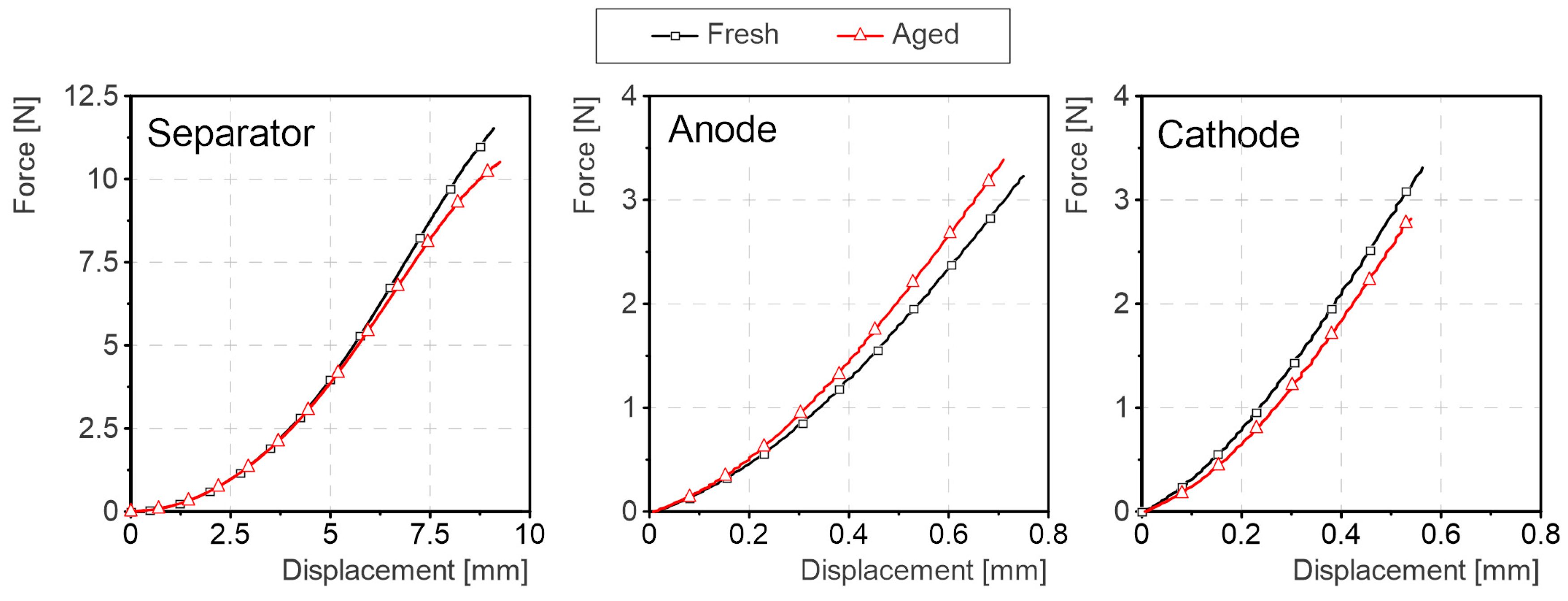
  • Puncture penetration tests + SEM cross-section of deformation zone:
    Puncture penetration tests were carried out in accordance with [44] in order to analyse the effect of localised loading of the active material in combination with bi-axial tension in the current collector. Thereby, a single layer sample (60 × 60 mm) was clamped in a fixture with a circular opening of a 35 mm diameter. A cone with a 3 mm tip radius and an angle of 6° is moved into the sample with a speed of 20 mm/min. This test was carried out with a Z3 universal test machine (displacement resolution of 0.01 mm) equipped with a 20 N (NTT, non-linearity ± 0.02%) load cell (see Figure 3b). As results, force over intrusion curves were generated for the fresh and aged samples of each battery component, with a minimum of five repetitions.
    In a second step, further cathode samples were loaded up to a force just below the detected failure threshold. Those critically loaded, but not failed samples were then prepared for a subsequent cross-section analysis, as already described above. The aim of this was to visualise the deformation pattern of the fresh and aged cathode active material directly under the tip. The focus, hereby, was laid on a possible reduction in the thickness of the active material, resulting from the local load and on the general curvature of the sample, as an indicator for possible changed shear properties.
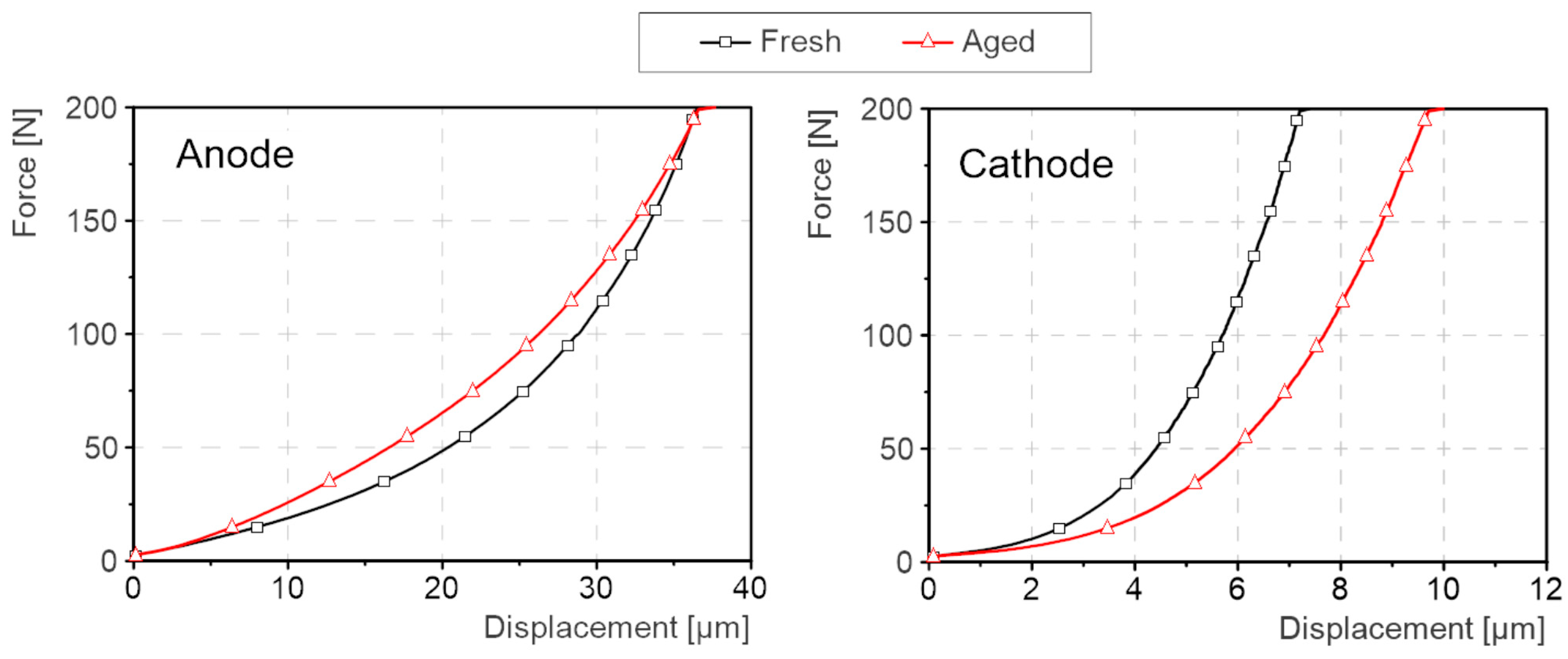
  • Compression tests:
    The puncture penetration tests, in combination with the analysis of the deformation area under the impactor, allowed for a qualitative assessment of different mechanical properties. In order to also quantify the change, complimentary compression tests of the electrode layers were carried out. Due to the very low layer thickness, typically stacked samples are examined in comparative studies in the recent literature. As already shown by [45] for fresh samples, a novel approach was used in this study to examine single electrode layers. Thereby, the possible influence of the mis-alignment of the layer stack, trapped liquid or gas in between layers, or other limitations are ruled out. A testing device of ZwickRoell, which is typically applied for the mechanical characterisation (compressibility) of paper and which features a displacement resolution of 0.04 µm, was adopted for these tests. A flat, circular impactor with a surface of 5 mm2 was pushed into the layer perpendicular to the surface with a speed of 0.2 mm/min and loaded to a maximum allowable peak force of 200 N. Figure 3c shows an exemplary picture of the test-head with a paper sample. For our tests, it was mounted on a ZwickRoell zwickiLine Z2.5 TN universal test machine. For each sample, a minimum of 3 repetitions were tested.
Figure 3. Component tests’ equipment used to characterise the cell components of fresh and aged cells; (a) RSA-G2 dynamic mechanic analyser used for conduction the uni-axial tensile tests; (b) Test equipment Z3 universal test machine with cone impactor according to [44] used for the puncture penetrations tests; (c) Single layer compression tests carried out using compressibility test head and zwickiLine Universal test machine of ZwickRoell.
Batteries 11 00099 g003

3. Results

3.1. Mechanical Cell Abuse Tests

In the mechanical abuse tests for either cell type (fresh and aged), a severe thermal runaway reaction, including the rupture of the pouch and fire, was observed in a fully charged state, whereas no relevant heating was seen for the cells tested in a discharged state. The respective sequences of the test conduction can be seen in Figure 4c,d.
Looking at the force–deflection data of the tests (Figure 4a), a comparable force onset for the four different cell states is seen, and the position of the peak force is correlating with the voltage drop (Figure 4b), indicating the failure point of the cells. For the fully charged cells, the impactor force drops to 0 N after reaching the failure point, as the cell material burns and disintegrates completely. In contrast, the impactor forces settle at a comparable level of around 25 kN for the discharged fresh and aged cells at intrusions beyond the failure point.
The captured data unveil significant differences in the mechanical behaviour of the fresh and the aged cells for both a charged and discharged state, as summarised in Table 1. The tolerable peak forces as well as the intrusion depth at failure reduce remarkably for the tested aged cells, which indicates a clearly more safety critical behaviour for the charged as well as discharged state.
In Figure 4a, the force–deflection curves show a drop of 14.2 kN (−26%) for an SOC of 100% and a drop of 12 kN (−27%) for an SOC of 0%, when comparing fresh and aged cells. The failure displacement is reduced by approximately 0.30 mm (−14%) for both cases. For the discharged cells, a clearly bigger force drop is seen for the fresh as compared to the aged cells, which show no prominent peak at all.
The cell voltage breaks down exactly at the level of deformation, at which the force drops for fresh and aged cells in a charged and discharged state. For the charged cells, a deeper voltage is observed for the aged samples, in contrast to the discharged cells, in which the voltage of the fresh cells reduces clearly further. The seen recovery of the cell voltage of the aged cells at an intrusion depth of about 3.2 mm should be disregarded, as the cell is already heavily burning at that state.
The shown abuse tests at a cell level were followed by a series of further component-level analyses to determine the cause of this significantly different and more critical behaviour of the aged cells.

3.2. Microscopic Imaging of Cell Components’ Structure

The surface and cross-section analysis of the cell components did show only minor differences in the separator. On the aged anode, surface changes in the morphology were observed along with a slight increase in the anode layer thickness, which both can be explained with the advanced degradation of the sample. The respective microscopic images are included in Appendix A (Figure A1, Figure A2, Figure A3 and Figure A4).
The aged cathode sample did show clear signs for NMC particle cracking on the surface as well as in the cross-section image. In Figure 5, the cross-section of the fresh and aged cathode samples are shown, highlighting the more pronounced grain boundaries and intergranular cracks in the NMC secondary particles. However, due to the still high state of health of the analysed aged battery (SoH 93%), the degradation of the particles is considered to be still comparably low. With respect to the layer thickness of the cathode, no change was observed. The superficial images of the cathode samples are included in Appendix A (Figure A5 and Figure A6).

3.3. Cell Component Mechanical Characterisation

Detailed material characterisation tests were carried out as a next step to identify which component of the cell was causing the different observed behaviour of the aged cells.

3.3.1. Tensile Tests of Cell Components

For the electrodes, tensile tests mainly examine the current collector’s properties, as the active material typically has a low influence on the response in pure tensile loading [41]. In our experiments, for either electrode, no weakening for the anode or even a slight stiffening of the material could be seen, which indicates that the aluminium (cathode) and copper (anode) current collectors of the aged cells remained intact. The somewhat stiffer behaviour of the anode samples could possibly be caused by the increase in the active material thickness, as observed in the microscopic images. For the separator, a slight reduction in stiffness was seen, however, at rather high strain levels that are considered not representative for the actual loading in the cell abuse test. The respective test data are included in Appendix B (Figure A7).
Generally, none of the aged components’ mechanical behaviour could serve as an explanation of that big change seen at a cell level.

3.3.2. Bi-Axial Tension (Puncture Penetration) + SEM of Deformation Zone

In puncture penetration loading, very little change from fresh to aged samples was found for the separator, in particular for the lower (relevant) strain levels, which is in line with the results of the uni-directional tensile tests carried out. The same was found for the anode for which a marginal stiffening of the response was seen. The respective force–deflection curves are included in Appendix B (Figure A8). The cathode did show a slight reduction in stiffness and failure force, as can be seen in Figure 6b.
In order to understand the mechanism of this changed behaviour, further samples were loaded just below the failure force, and section cuts were created and analysed with SEM. Figure 6a shows the respective images of the fresh and aged samples, with a focus on the deformation zone directly under the tip. Thereby, differences can be seen in particular with respect to the curvature of the electrode portion directly under the impactor tip. The aged cathode sample did show a rather curved section as compared to the fresh sample, which is almost straight, limited with small-radius transition areas (highlighted with the green circles). In this area, apparently a higher degree of material damage is present—some of the active material was completely loose and got removed during the sample preparation and the resulting voids were filled with embedding resin, seen as “black” regions in the right green circle.
No change in the layer thickness of the active material could be detected either in the aged or in the fresh samples.

3.3.3. Compression Tests

In addition to the puncture penetration tests, which allowed only a qualitative analysis of the active material properties, complementary compression tests were carried out to quantify the differences between fresh and aged samples. Figure 6c shows a clearly less stiff aged cathode as compared to its fresh counterpart; for a linearised stiffness between 100 N and 200 N, the reduction amounts to 19 N/µm, which represents a reduction of −29%.
For the anode, a similar stiffening, as already seen in the tension and puncture penetration tests, was observed; however, the differences between fresh and aged are comparably low. Respective experimental data are included in Appendix B (Figure A9).

4. Discussion

In contrast to other yet published studies, the examined aged cells did show a clearly more safety critical behaviour in the analysed mechanical abuse load. Based on the carried out complementary experiments and analyses, the hypothesis was derived that the well-established degradation mechanism of cathode active material (NMC) particle cracking is the predominant cause of the different behaviour.
NMC is a granular active material that builds up from the primary particles (NMC grains), which are processed to form bigger scale conglomerate spheres (secondary particles) using a binder material. The binder is a polymeric material, which plays an important role of not only bonding the conductive active material particles together but also to the current collector [46,47]. The binder also maintains the electrode’s structural integrity [46] and accommodates strain during electrochemical cycling [48]. For the analysed cell, the mentioned secondary particles are clearly visible in Figure A3 in Appendix A. During aging and the related cyclic volume expansion of the particles, along the grain boundaries, a new surface is exposed to the electrolyte, which causes side reactions that result in a debonding of the grains linked with the growth of the grain boundaries. So, the initially stable spheres transform to debonded smaller scale grains, which is clearly leading to different mechanical properties. These grains are also reported to be prone to suffer intragranular cracks as a result of degradation [15,16,17]; this, however, could not be detected in our cell. In general, a stable solid layer of an active material, capable of distributing local compressive loads on the layer surface over a wide region on the aluminium current collector, transforms into a yielding, shear weak layer, resulting in a direct, localised transfer of the load, which causes the disintegration of the active material layer and current collector failure at lower loading intensities, as described in [7].
All tests that were carried out support this hypothesis: In the compression tests (Figure 6c), the weaker material response is obvious and could be quantified to a reduction in stiffness of −29%. In the puncture penetration tests, the failure at a lower force and the reduction in stiffness are indirect indicators, as in this test configuration, only the effect of the active material’s properties on the failure of the aluminium current collector is seen. The fresh active material is calendared onto the aluminium current collector and builds a stable, shear stiff layer of joint particles of different sizes. Under the compression load, the layer behaves as a bending-stiff cap that distributes the local load over a wider area around the impactor until the layer fails based on shear. This behaviour could be observed in the SEM images of the deformed samples in Figure 6a. The more disjointed and loose primary particles of the aged cathode active material layer are yielding under the impactor tip, thus transferring the local compression load through the layer to the aluminium current collector with little distribution into the material next to the tip. The resulting more localised loads on the current collector ultimately cause the earlier failure, as seen in Figure 6b. An overall weakening of the cathode current collector due to other known degradation mechanisms (e.g., current collector corrosion, cracking [17,21,42]) could be ruled out considering the uni-directional tensile tests. The fresh NMC layer exhibits a more brittle mechanical behaviour as compared to the aged layer, in which the secondary particles are partly disintegrated.
The derived hypothesis can partly also be supported by the cell-level tests: Looking at the data of the discharged cells (Figure 4a), a big force drop after failure is observed for the fresh cell in comparison with almost no visible drop for the aged cells. This force drop also indicates a brittle, instant failure of cell components. The related deeper voltage drop for the discharged fresh cells (Figure 4b) also fits into the picture that multiple layers fail instantly and cause a bigger damage in the layup, as compared to the slowly increasing failure zone as a result of the protruding impactor in the aged cell.
The analysed aged cell did unveil a notably different characteristic to most of the other yet published studies dealing with this topic. One clear difference was that the repeatedly described right shift of the force–deflection data (for pouch cells in lateral indentation loads) was not seen in our experiments. The mentioned right shift is typically explained by the formation of additional layers in the battery (SEI, Lithium Plating, gas formation [4,39,49,50,51]), which leads to a “softer” onset of the mechanical response. These additional layers are in line with the degree of degradation of the battery (SoH) and sum up to increased thicknesses of aged cells. This right shift was typically not going along with a severe drop in the maximum tolerable forces, and partly the analysed aged cells were therefore considered “safer”. In contrast to other studies, in the present investigation, a cell was analysed that did feature a still high state of health (93%) and a comparably low thickness increase (+3%), which could explain this different effect. In another study [52], the same cell was artificially aged to an SoH of around 80% (comparable to most other sources), thereby specifically triggering the degradation effect of lithium plating in the cell. In these conditions, the cell thickness increased to 12.27 mm and the above mentioned “right-shift” could clearly be observed. This underlies the relation of the cell thickness increase and degradation state to the described effect.
A noteworthy issue is that these specific cells did, on the one hand, show the right shift of the force–deflection curve, as discussed above, but did also feature comparably reduced failure forces for both the charged and discharged state, as seen in the present study, which would allow the assumption that the different behaviour is related to the specific analysed cell. Whereas most other studies also used NMC in different configurations as a cathode active material [35,37,38], only our cell used a graphite/SiOx anode. However, a clear correlation to the found behaviour could not be drawn.
Another clear difference to most other yet published studies addressing this research field is found in the state of the analysed LIB. Typically, cells are artificially aged in laboratories to reach a specific degradation level. This is either achieved by a simplified generic cycling protocol with specific, clearly defined boundary conditions (e.g., currents, voltage window, constant temperatures, …) or alternatively by a procedure that is derived from usage (specific charge and discharge profiles, different durations at specific charge levels, temperature range…). Any of those disregards any other influence from “real” usage that could potentially also alter the battery’s properties (vibrations, environmental conditions, …). In the present study, batteries were analysed that were used in a car, which as a drawback, limits the insight into understanding why a specific degradation mode formed during the usage and how it evolved over time. However, cells that were used in a car, that was driven according to a defined user profile, are considered to be the most realistically aged sample available for such type of study.
One very clear finding is based on the analysis of the present study and other work, that the residual capacity (SoH) is not a suitable indicator for the safety of a cell. Even though, for our cell, a still high electrical performance is left, the safety-relevant mechanical properties degraded significantly. This emphasises the need to understand the correlation of safety-relevant changes in the battery with quantifiable metrics. The first studies with that scope of work were already published by [53,54].

5. Conclusions

In this work, aged cells were analysed that did show a significantly more critical behaviour in terms of mechanical stability and thus crash-safety, as compared to the same cell in a fresh state. Whereas the reason for the changed mechanical properties could be traced down to NMC particle cracking as the most likely responsible degradation mode, deviations and opposite findings compared to other studies could not be explained. It is, however, expected that our results are not in conflict with other work, but represent complementary data with different findings. The effect of ageing, in its different forms, has been analysed for a long time with a focus on electrical performance. The mechanical degradation as a function of different chemistries or cell formats is considered to be a relatively new scope of view and, therefore, is still widely unknown. On top of that, the usage of the battery (environmental conditions, user profile, charging, …) leads to significantly different ageing rates and modes; however, the influence of the safety of batteries is yet unknown.
The results of our study, in combination with other yet published investigations, underly the importance of further investigations in this research field. It has to be made sure that from a mechanical point of view, the most critical state of an EES is used as a base for the design of crashworthiness features in an EV. As found in our study, this could likely be not a pristine battery, but an EES that has already been used for some time. This immediately triggers the question of how such a state of a battery can be reproduced realistically, and with the least possible effort, as a prerequisite for an efficient design process.
From our perspective, given the vast variety of degradation mechanisms and influencing factors depending on the usage of an EES, for current and, as is increasingly important, for future EVs, a considerable knowledge gap is still present.

Author Contributions

Conceptualisation: G.G. and S.M.A.; Methodology: G.G. and S.M.A.; Formal analysis, Data curation: G.G., S.M.A. and M.W.; Investigation and visualisation: G.G. and S.M.A.; Validation: G.G.; Writing—original draft preparation: G.G. and S.M.A.; Writing—review and editing: E.E. and C.E.; Supervision, project administration and funding acquisition: C.E. All authors have read and agreed to the published version of the manuscript.

Funding

This work originates from the research project SafeLIB. The COMET Project SafeLIB is funded within the framework of COMET—Competence Centers for Excellent Technologies (Grant agreement No. 882506) by BMK, BMDW, the Province of Upper Austria, the province of Styria as well as SFG. The COMET Program is managed by FFG. The authors thank the consortium members of the SafeLIB project for supporting this work. Supported by the Open Access Funding by the Graz University of Technology.

Data Availability Statement

Data are contained within the article.

Acknowledgments

Open Access Funding by the Graz University of Technology. The authors thank the consortium members of the SafeLIB project for their valuable input to this work. The authors would also like to thank our former colleague Georgi Kovachev, who was very supportive of this research at the beginning.

Conflicts of Interest

Author Eduard Ewert is employed by the Dr. Ing. h.c. F. Porsche AG. Author Michael Wenzl is employed by the ZwickRoell GmbH & Co. KG. The remaining authors declare that the research was conducted in the absence of any commercial or financial relationships that could be construed as a potential conflict of interest.

Appendix A. Microscopic Imaging

Appendix A.1. Anode

Figure A1. Comparison of fresh (left) and aged (right) anode surface exhibits morphological differences.
Batteries 11 00099 g0a1
Figure A2. Comparison of fresh (left) and aged (right) anode cross-section exhibits slight thickness increase in aged sample; light gray spots are SiO particles.
Batteries 11 00099 g0a2

Appendix A.2. Cathode

Figure A3. Comparison of fresh (left) and aged (right) cathode surface shows tendency towards smaller secondary NMC particles.
Batteries 11 00099 g0a3
Figure A4. Comparison of fresh (left) and aged (right) cathode cross-section exhibits no thickness increase in aged sample; tendency to better visible grain boundaries on aged sample indicating progressed particle cracking.
Batteries 11 00099 g0a4

Appendix A.3. Separator

Figure A5. Comparison of fresh (left) and aged (right) separator surface (light gray areas are fractions of Al coating).
Batteries 11 00099 g0a5
Figure A6. Comparison of fresh (left) and aged (right) separator cross-section exhibits no thickness increase in aged sample.
Batteries 11 00099 g0a6

Appendix B. Component Testing

Appendix B.1. Tensile Test

Figure A7. Results of the tensile tests of the different cell components for fresh and aged cells.
Batteries 11 00099 g0a7

Appendix B.2. Puncture Penetration Test

Figure A8. Results of the puncture penetration tests of the different cell components for fresh and aged cells.
Batteries 11 00099 g0a8

Appendix B.3. Compression Tests

Figure A9. Results of the single layer compression tests for fresh and aged anode and cathode.
Batteries 11 00099 g0a9

References

  1. European Environment Agency. Transport and Environment Report 2021: Decarbonising Road Transport—The Role of Vehicles, Fuels and Transport Demand; EEA Report No 02/2022 TH-AL-22-004-EN-N; European Environment Agency: Copenhagen, Denmark, 2022. [Google Scholar]
  2. Parera, N.; Amor, O. Safety Protocols for Electric Vehicles Crash Tests. J. Soc. Automot. Eng. Malays. 2019, 3, 112–122. [Google Scholar] [CrossRef]
  3. Navale, A.B.; Chippa, S.P.; Chougule, D.A.; Raut, P.M. Crashworthiness aspects of electric vehicle design. Int. J. Crashworthiness 2021, 26, 368–387. [Google Scholar] [CrossRef]
  4. Birkl, C.R.; Roberts, M.R.; McTurk, E.; Bruce, P.G.; Howey, D.A. Degradation diagnostics for lithium ion cells. J. Power Sources 2017, 341, 373–386. [Google Scholar] [CrossRef]
  5. Xiong, R.; Pan, Y.; Shen, W.; Li, H.; Sun, F. Lithium-ion battery aging mechanisms and diagnosis method for automotive applications: Recent advances and perspectives. Renew. Sustain. Energy Rev. 2020, 131, 110048. [Google Scholar] [CrossRef]
  6. Vetter, J.; Novák, P.; Wagner, M.R.; Veit, C.; Möller, K.-C.; Besenhard, J.O.; Winter, M.; Wohlfahrt-Mehrens, M.; Vogler, C.; Hammouche, A. Ageing mechanisms in lithium-ion batteries. J. Power Sources 2005, 147, 269–281. [Google Scholar] [CrossRef]
  7. Wu, S.; Chen, Y.; Luan, W.; Chen, H.; Huo, L.; Wang, M.; Tu, S.-t. A Review of Multiscale Mechanical Failures in Lithium-Ion Batteries: Implications for Performance, Lifetime and Safety. Electrochem. Energ. Rev. 2024, 7, 35. [Google Scholar] [CrossRef]
  8. Sun, S.; Xu, J. Safety behaviors and degradation mechanisms of aged batteries: A review. Energy Mater. Devices 2024, 2, 9370048. [Google Scholar] [CrossRef]
  9. Yang, X.-G.; Leng, Y.; Zhang, G.; Ge, S.; Wang, C.-Y. Modeling of lithium plating induced aging of lithium-ion batteries: Transition from linear to nonlinear aging. J. Power Sources 2017, 360, 28–40. [Google Scholar] [CrossRef]
  10. Chen, Y.; Luan, W.; Chen, H.; Zhu, X. Multi-scale Failure Behavior of Cathode in Lithium-ion Batteries Based on Stress Field. J. Inorg. Mater. 2022, 777, 918–924. [Google Scholar] [CrossRef]
  11. Li, J.; Dozier, A.K.; Li, Y.; Yang, F.; Cheng, Y.-T. Crack Pattern Formation in Thin Film Lithium-Ion Battery Electrodes. J. Electrochem. Soc. 2011, 158, A689. [Google Scholar] [CrossRef]
  12. Yuca, N.; Zhao, H.; Song, X.; Dogdu, M.F.; Yuan, W.; Fu, Y.; Battaglia, V.S.; Xiao, X.; Liu, G. A systematic investigation of polymer binder flexibility on the electrode performance of lithium-ion batteries. ACS Appl. Mater. Interfaces 2014, 6, 17111–17118. [Google Scholar] [CrossRef] [PubMed]
  13. Chen, Y.; Chen, H.; Luan, W. Shakedown, ratcheting and fatigue analysis of cathode coating in lithium-ion battery under steady charging-discharging process. J. Mech. Phys. Solids 2021, 150, 104366. [Google Scholar] [CrossRef]
  14. Luo, H.; Zhu, J.; Sahraei, E.; Xia, Y. Adhesion strength of the cathode in lithium-ion batteries under combined tension/shear loadings. RSC Adv. 2018, 8, 3996–4005. [Google Scholar] [CrossRef]
  15. Xu, R.; Yang, Y.; Yin, F.; Liu, P.; Cloetens, P.; Liu, Y.; Lin, F.; Zhao, K. Heterogeneous damage in Li-ion batteries: Experimental analysis and theoretical modeling. J. Mech. Phys. Solids 2019, 129, 160–183. [Google Scholar] [CrossRef]
  16. Sun, H.H.; Pollard, T.P.; Borodin, O.; Xu, K.; Allen, J.L. Degradation of High Nickel Li-Ion Cathode Materials Induced by Exposure to Fully-Charged State and Its Mitigation. Adv. Energy Mater. 2023, 13, 2204360. [Google Scholar] [CrossRef]
  17. Rahe, C.; Kelly, S.T.; Rad, M.N.; Sauer, D.U.; Mayer, J.; Figgemeier, E. Nanoscale X-ray imaging of ageing in automotive lithium ion battery cells. J. Power Sources 2019, 433, 126631. [Google Scholar] [CrossRef]
  18. Dubarry, M.; Truchot, C.; Liaw, B.Y.; Gering, K.; Sazhin, S.; Jamison, D.; Michelbacher, C. Evaluation of commercial lithium-ion cells based on composite positive electrode for plug-in hybrid electric vehicle applications. Part II. Degradation mechanism under 2C cycle aging. J. Power Sources 2011, 196, 10336–10343. [Google Scholar] [CrossRef]
  19. Jalkanen, K.; Karppinen, J.; Skogström, L.; Laurila, T.; Nisula, M.; Vuorilehto, K. Cycle aging of commercial NMC/graphite pouch cells at different temperatures. Appl. Energy 2015, 154, 160–172. [Google Scholar] [CrossRef]
  20. Braithwaite, J.W. Corrosion of Lithium-Ion Battery Current Collectors. J. Electrochem. Soc. 1999, 146, 448. [Google Scholar] [CrossRef]
  21. Guo, M.; Meng, W.; Zhang, X.; Bai, Z.; Wang, G.; Wang, Z.; Yang, F. Structural Degradation of Cu Current Collector During Electrochemical Cycling of Sn-Based Lithium-Ion Batteries. J. Electron. Mater. 2019, 48, 7543–7550. [Google Scholar] [CrossRef]
  22. Kalnaus, S.; Wang, Y.; Li, J.; Kumar, A.; Turner, J.A. Temperature and strain rate dependent behavior of polymer separator for Li-ion batteries. Extrem. Mech. Lett. 2018, 20, 73–80. [Google Scholar] [CrossRef]
  23. Cannarella, J.; Liu, X.; Leng, C.Z.; Sinko, P.D.; Gor, G.Y.; Arnold, C.B. Mechanical Properties of a Battery Separator under Compression and Tension. J. Electrochem. Soc. 2014, 161, F3117–F3122. [Google Scholar] [CrossRef]
  24. Gor, G.Y.; Cannarella, J.; Leng, C.Z.; Vishnyakov, A.; Arnold, C.B. Swelling and softening of lithium-ion battery separators in electrolyte solvents. J. Power Sources 2015, 294, 167–172. [Google Scholar] [CrossRef]
  25. Zhang, X.; Zhu, J.; Sahraei, E. Degradation of battery separators under charge–discharge cycles. RSC Adv. 2017, 7, 56099–56107. [Google Scholar] [CrossRef]
  26. Demirocak, D.E.; Bhushan, B. Probing the aging effects on nanomechanical properties of a LiFePO4 cathode in a large format prismatic cell. J. Power Sources 2015, 280, 256–262. [Google Scholar] [CrossRef]
  27. Chen, Y.; Santhanagopalan, S.; Babu, V.; Ding, Y. Dynamic mechanical behavior of lithium-ion pouch cells subjected to high-velocity impact. Compos. Struct. 2019, 218, 50–59. [Google Scholar] [CrossRef]
  28. Kermani, G.; Sahraei, E. Review: Characterization and Modeling of the Mechanical Properties of Lithium-Ion Batteries. Energies 2017, 10, 1730. [Google Scholar] [CrossRef]
  29. Sahraei, E.; Meier, J.; Wierzbicki, T. Characterizing and modeling mechanical properties and onset of short circuit for three types of lithium-ion pouch cells. J. Power Sources 2014, 247, 503–516. [Google Scholar] [CrossRef]
  30. Feng, X.; Ouyang, M.; Liu, X.; Lu, L.; Xia, Y.; He, X. Thermal runaway mechanism of lithium ion battery for electric vehicles: A review. Energy Storage Mater. 2018, 10, 246–267. [Google Scholar] [CrossRef]
  31. Abaza, A.; Ferrari, S.; Wong, H.K.; Lyness, C.; Moore, A.; Weaving, J.; Blanco-Martin, M.; Dashwood, R.; Bhagat, R. Experimental study of internal and external short circuits of commercial automotive pouch lithium-ion cells. J. Energy Storage 2018, 16, 211–217. [Google Scholar] [CrossRef]
  32. Maleki, H.; Wang, H.; Porter, W.; Hallmark, J. Li-Ion polymer cells thermal property changes as a function of cycle-life. J. Power Sources 2014, 263, 223–230. [Google Scholar] [CrossRef]
  33. Vertiz, G.; Oyarbide, M.; Macicior, H.; Miguel, O.; Cantero, I.; Fernandez de Arroiabe, P.; Ulacia, I. Thermal characterization of large size lithium-ion pouch cell based on 1d electro-thermal model. J. Power Sources 2014, 272, 476–484. [Google Scholar] [CrossRef]
  34. Richter, F.; Vie, P.J.S.; Kjelstrup, S.; Burheim, O.S. Measurements of ageing and thermal conductivity in a secondary NMC-hard carbon Li-ion battery and the impact on internal temperature profiles. Electrochim. Acta 2017, 250, 228–237. [Google Scholar] [CrossRef]
  35. Sprenger, M.; Dölle, N.; Schauwecker, F.; Raffler, M.; Ellersdorfer, C.; Sinz, W. Multiscale Analysis and Safety Assessment of Fresh and Electrical Aged Lithium-Ion Pouch Cells Focusing on Mechanical Behavior. Energies 2022, 15, 847. [Google Scholar] [CrossRef]
  36. Sprenger, M.; Kovachev, G.; Dölle, N.; Schauwecker, F.; Sinz, W.; Ellersdorfer, C. Changes in the Mechanical Behavior of Electrically Aged Lithium-Ion Pouch Cells: In-Plane and Out-of-Plane Indentation Loads with Varying Testing Velocity and State of Charge. Batteries 2023, 9, 67. [Google Scholar] [CrossRef]
  37. Luo, H.; Xia, Y.; Zhou, Q. Mechanical damage in a lithium-ion pouch cell under indentation loads. J. Power Sources 2017, 357, 61–70. [Google Scholar] [CrossRef]
  38. Liu, Y.; Xia, Y.; Zhou, Q. Effect of low-temperature aging on the safety performance of lithium-ion pouch cells under mechanical abuse condition: A comprehensive experimental investigation. Energy Storage Mater. 2021, 40, 268–281. [Google Scholar] [CrossRef]
  39. Kovachev, G.; Ellersdorfer, C.; Gstrein, G.; Hanzu, I.; Wilkening, H.M.R.; Werling, T.; Schauwecker, F.; Sinz, W. Safety assessment of electrically cycled cells at high temperatures under mechanical crush loads. eTransportation 2020, 6, 100087. [Google Scholar] [CrossRef]
  40. Kovachev, G.; Schröttner, H.; Gstrein, G.; Aiello, L.; Hanzu, I.; Wilkening, H.M.R.; Foitzik, A.; Wellm, M.; Sinz, W.; Ellersdorfer, C. Analytical Dissection of an Automotive Li-Ion Pouch Cell. Batteries 2019, 5, 67. [Google Scholar] [CrossRef]
  41. Zhang, C.; Xu, J.; Cao, L.; Wu, Z.; Santhanagopalan, S. Constitutive behavior and progressive mechanical failure of electrodes in lithium-ion batteries. J. Power Sources 2017, 357, 126–137. [Google Scholar] [CrossRef]
  42. Guo, L.; Thornton, D.B.; Koronfel, M.A.; Stephens, I.E.L.; Ryan, M.P. Degradation in lithium ion battery current collectors. J. Phys. Energy 2021, 3, 032015. [Google Scholar] [CrossRef]
  43. ASTM D882-02; Standard Test Method for Tensile Properties of Thin Plastic Sheeting. ASTM International: West Conshohocken, PA, USA, 2010.
  44. ASTM F1306-21; Standard Test Method for Slow Rate Penetration Resistance of Flexible Barrier Films and Laminates. ASTM International: West Conshohocken, PA, USA, 2021.
  45. Schmid, A.; Ellersdorfer, C.; Ewert, E.; Feist, F. Sequential Multi-Scale Modeling Using an Artificial Neural Network-Based Surrogate Material Model for Predicting the Mechanical Behavior of a Li-Ion Pouch Cell Under Abuse Conditions. Batteries 2024, 10, 425. [Google Scholar] [CrossRef]
  46. Chen, H.; Ling, M.; Hencz, L.; Ling, H.Y.; Li, G.; Lin, Z.; Liu, G.; Zhang, S. Exploring Chemical, Mechanical, and Electrical Functionalities of Binders for Advanced Energy-Storage Devices. Chem. Rev. 2018, 118, 8936–8982. [Google Scholar] [CrossRef] [PubMed]
  47. Dou, W.; Zheng, M.; Zhang, W.; Liu, T.; Wang, F.; Wan, G.; Liu, Y.; Tao, X. Review on the Binders for Sustainable High-Energy-Density Lithium Ion Batteries: Status, Solutions, and Prospects. Adv. Funct. Mater. 2023, 33, 2305161. [Google Scholar] [CrossRef]
  48. Iqbal, N.; Ali, Y.; Lee, S. Chemo-mechanical response of composite electrode systems with multiple binder connections. Electrochim. Acta 2020, 364, 137312. [Google Scholar] [CrossRef]
  49. Orsini, F.; Du Pasquier, A.; Beaudoin, B.; Tarascon, J.M.; Trentin, M.; Langenhuizen, N.; de Beer, E.; Notten, P. In situ Scanning Electron Microscopy (SEM) observation of interfaces within plastic lithium batteries. J. Power Sources 1998, 76, 19–29. [Google Scholar] [CrossRef]
  50. Sagane, F.; Shimokawa, R.; Sano, H.; Sakaebe, H.; Iriyama, Y. In-situ scanning electron microscopy observations of Li plating and stripping reactions at the lithium phosphorus oxynitride glass electrolyte/Cu interface. J. Power Sources 2013, 225, 245–250. [Google Scholar] [CrossRef]
  51. Luo, D.; Li, M.; Zheng, Y.; Ma, Q.; Gao, R.; Zhang, Z.; Dou, H.; Wen, G.; Shui, L.; Yu, A.; et al. Electrolyte Design for Lithium Metal Anode-Based Batteries Toward Extreme Temperature Application. Adv. Sci. 2021, 8, e2101051. [Google Scholar] [CrossRef]
  52. Abbas, S.M.; Gstrein, G.; Jauernig, A.D.; Schmid, A.; Michelini, E.; Hinterberger, M.; Ellersdorfer, C. Influence of Lithium Plating on mechanical properties of commercial LiIon batteries. Batteries 2025. manuscript in preparation. [Google Scholar]
  53. Michelini, E.; Höschele, P.; Abbas, S.M.; Ellersdorfer, C.; Moser, J. Assessment of Health Indicators to Detect the Aging State of Commercial Second-Life Lithium-Ion Battery Cells through Basic Electrochemical Cycling. Batteries 2023, 9, 542. [Google Scholar] [CrossRef]
  54. Che, Y.; Guo, J.; Zheng, Y.; Stroe, D.-I.; Liu, W.; Hu, X.; Teodorescu, R. Unlocking Interpretable Prediction of Battery Random Discharge Capacity with Domain Adaptative Physics Constraint. Adv. Energy Mater. 2025, 4, 2405506. [Google Scholar] [CrossRef]
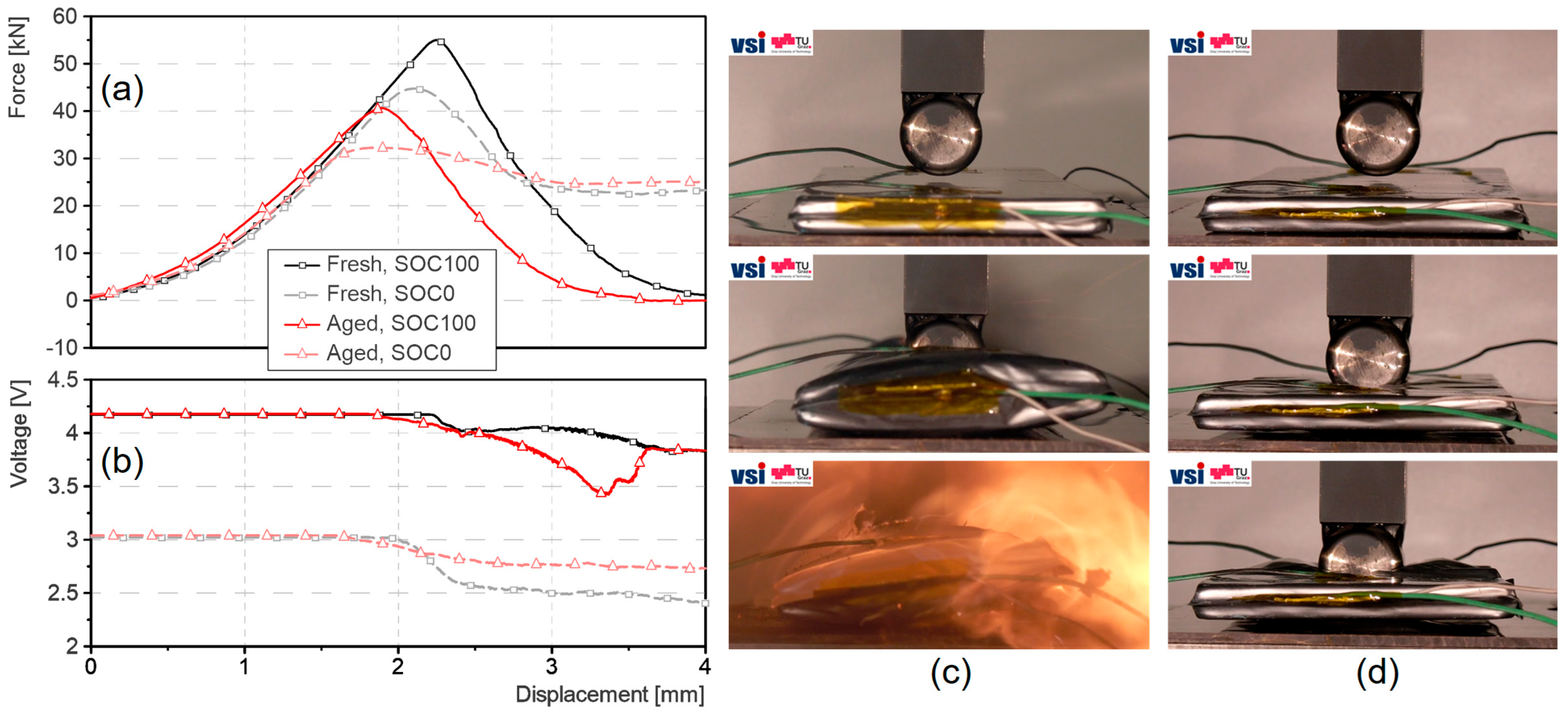
Figure 1. Characteristics of the analysed fresh and aged LIBs. (a) 1C charge and discharge capacities of fresh and aged cells at room temperature; (b) overview of cell thickness as function of SoC for fresh and aged cells—mean value + corridors including all samples.
Batteries 11 00099 g001
Figure 2. Setup of mechanical abuse tests on cell level.
Batteries 11 00099 g002
Figure 4. Results of cell-level abuse tests. (a) Force vs. intrusion data; (b) voltage signals during intrusion; (c) sequence of intrusion test with a fully charged cell; (d) sequence of intrusion test with a discharged cell.
Batteries 11 00099 g004
Figure 5. Comparison of fresh and aged cathode structure in cross-section images with Al-current collector (dark gray, left edge of image) and NMC particles (light gray). (a) Sample from fresh cathode; (b) sample from aged cathode with clearly visible grain boundaries and intergranular cracks; (c) detailed view on cracked NMC secondary particle.
Batteries 11 00099 g005
Figure 6. Results of mechanical characterisation of single cell components. (a) SEM cross-section images of cathode layer deformation pattern in puncture penetration test directly under impactor tip (impactor geometry represented by blue dotted line); (b) cathode layer response in puncture penetration test shows slightly less stiffness and peak force for aged sample; (c) clearly less stiff material response of aged cathode sample in flat compression test. In (b,c), the mean values of the tests and the range of results are visualised.
Batteries 11 00099 g006
Table 1. Overview of cell test results for different tested cells and highlighted changes for fresh (F) and aged (RA) cells (mean value of conducted tests + bandwidth of test results).
Peak Force [kN]Dsp @ Failure [mm]Difference to F
SOC 100%SOC 0%SOC 100%SOC 0%Peak Force [kN]Dsp @ Failure [mm]
F55.6 ± 1.245.2 ± 0.42.27 ± 0.052.09 ± 0.03SOC 100%SOC 0%SOC 100%SOC 0%
RA41.4 ± 0.533.2 ± 0.31.94 ± 0.041.79 ± 0.04−14.2 (−26%)−12.0 (−27%)−0.32 (−14%)−0.30 (−14%)
Disclaimer/Publisher’s Note: The statements, opinions and data contained in all publications are solely those of the individual author(s) and contributor(s) and not of MDPI and/or the editor(s). MDPI and/or the editor(s) disclaim responsibility for any injury to people or property resulting from any ideas, methods, instructions or products referred to in the content.

