Article

Plasticized Ionic Liquid Crystal Elastomer Emulsion-Based Polymer Electrolyte for Lithium-Ion Batteries

1
Department of Physics, Kent State University, Kent, OH 44242, USA
2
School of Polymer Science and Polymer Engineering, University of Akron, Akron, OH 44325, USA
3
Materials Science Graduate Program and Advanced Materials and Liquid Crystal Institute, Kent, OH 44242, USA
*
Author to whom correspondence should be addressed.
Batteries 2025, 11(3), 106; https://doi.org/10.3390/batteries11030106
Submission received: 12 February 2025 / Revised: 1 March 2025 / Accepted: 11 March 2025 / Published: 12 March 2025
(This article belongs to the Special Issue Recent Advances of All-Solid-State Battery)

Abstract

:
The development and electrochemical characteristics of ionic liquid crystal elastomers (iLCEs) are described for use as electrolyte components in lithium-ion batteries. The unique combination of elastic and liquid crystal properties in iLCEs grants them robust mechanical attributes and structural ordering. Specifically, the macroscopic alignment of phase-segregated, ordered nanostructures in iLCEs serves as an ion pathway, which can be solidified through photopolymerization to create ion-conductive solid-state polymer lithium batteries (SSPLBs) with high ionic conductivity (1.76 × 10⁻³ S cm−1 at 30 °C), and a high (0.61) transference number. Additionally, the rubbery state ensures good interfacial contact with electrodes that inhibits lithium dendrite formation. Furthermore, in contrast to liquid electrolytes, the iLCE shrinks upon heating, thus preventing any overheating-related explosions. The Li/LiFePO4 (LFP) cells fabricated using iLCE-based solid electrolytes show excellent cycling stability with a discharge capacity of ~124 mAh g−1 and a coulombic efficiency close to 100%. These results are promising for the practical application of iLCE-based SSPLBs.

Graphical Abstract

1. Introduction

There is an urgent need to develop improved electrolytes for lithium-ion batteries by investigating novel materials that can meet the increasing demands for energy, power, and safety in modern storage systems [1,2,3,4,5,6,7,8,9,10]. Various solid electrolyte technologies have emerged as promising alternatives to traditional liquid electrolytes, including inorganic ceramic electrolytes (ICE) [11,12,13], solid polymer electrolytes (SPE) [14,15,16,17,18,19], and recently, polymer electrolyte membranes (PEM), for high-performance energy storage applications [9,10,20,21,22,23,24,25,26,27,28,29,30]. Due to their structural characteristics, solid polymer electrolytes typically suffer from limited ionic conductivity (roughly 10−8 to 10−6 S cm−1). To enhance ion conduction, researchers commonly employ strategies such as facilitating lithium salt dissociation and incorporating dinitrile-derivative (NC-(CH2)n-CN) plasticizers like succinonitrile (SCN, n = 2) [25,31]. These additives improve ion mobility, achieving conductivities of up to 10−4 to 10−3 S cm−1 at ambient temperature by lowering glass transition temperatures (Tg) and enhancing chain dynamics. Currently, polyethylene oxide (PEO)-based materials are the leading choice for polymer hosts in PEMs due to PEO’s high dielectric constant, excellent ability to solvate Li+ ions, and favorable chain flexibility. Additionally, PEO is valued for its ease of preparation, cost-effectiveness, reasonable electrochemical stability, and safety features. However, standard linear PEO-based PEMs typically show low ionic conductivities ( 10 4   S   c m 1 ) at room temperature (RT) by virtue of the high crystallinity of the PEO chains [32,33,34]. Various approaches to improve ionic conductivities, such as block copolymer electrolytes [35,36], crosslinked polymer electrolytes [37,38], interpenetrating network polymer electrolytes [39], and composite polymer electrolytes [40], have been proposed, with promising results. Despite this, most PEO-based PEMs exhibit lithium-ion transference numbers (the fraction of the total electric current carried in an electrolyte by a positive ion) below 0.4. To achieve acceptable battery performance, solid-state polymer lithium batteries (SSPLBs) using these PEMs generally need to operate at around 60 °C, because of their limited ionic conductivities and high electrode/electrolyte interfacial resistances [41].
Consequently, it is essential to develop an optimized PEM with highly selective Li+ transport characteristics both in bulk and at interfaces to enable SSPLBs to function effectively at room temperature (RT). The concept of using fluid ionic liquid crystals (iLCs) with ion channels as ion-conductive films and liquid iLCs-based batteries has been proposed before and it has been shown that imidazolium salts in iLCs can form liquid crystals for long enough alkyl chains [42,43,44,45,46,47,48].
In this study, we explore the potential of ionic liquid crystal elastomers (iLCEs) [49], as a novel promising PEM constituent, which, to the best of our knowledge, is the first study to demonstrate the potential practical application of solid ionic liquid crystal elastomer (iLCE)-based SSPLBs. The appeal of iLCEs lies in their ability to maintain an orientational order over a wide temperature range and their capacity to contract at increasing temperatures [50], thereby reducing pressure on electrode surfaces or interfaces. Their organized ion pathways can be solidified through photopolymerization to create nanostructured ion-conductive electrolyte networks. Additionally, integrating SCN into well-defined iLCE structures can significantly enhance Li+ transport efficiency. Based on this concept, we developed a freestanding and flexible solid electrolyte through the in situ photopolymerization of iLCE/SCN/lithium bis(trifluoromethyl sulfonyl)imide (LiTFSI) for use in ambient-temperature SSPLBs (Figure S4). The resulting iLCE-based PEM exhibits exceptional electrochemical properties, including high ionic conductivity, excellent compatibility with electrodes, and the effective suppression of lithium dendrite growth.

2. Results

The Experimental Section and Methods are described in Supporting Information (SI).

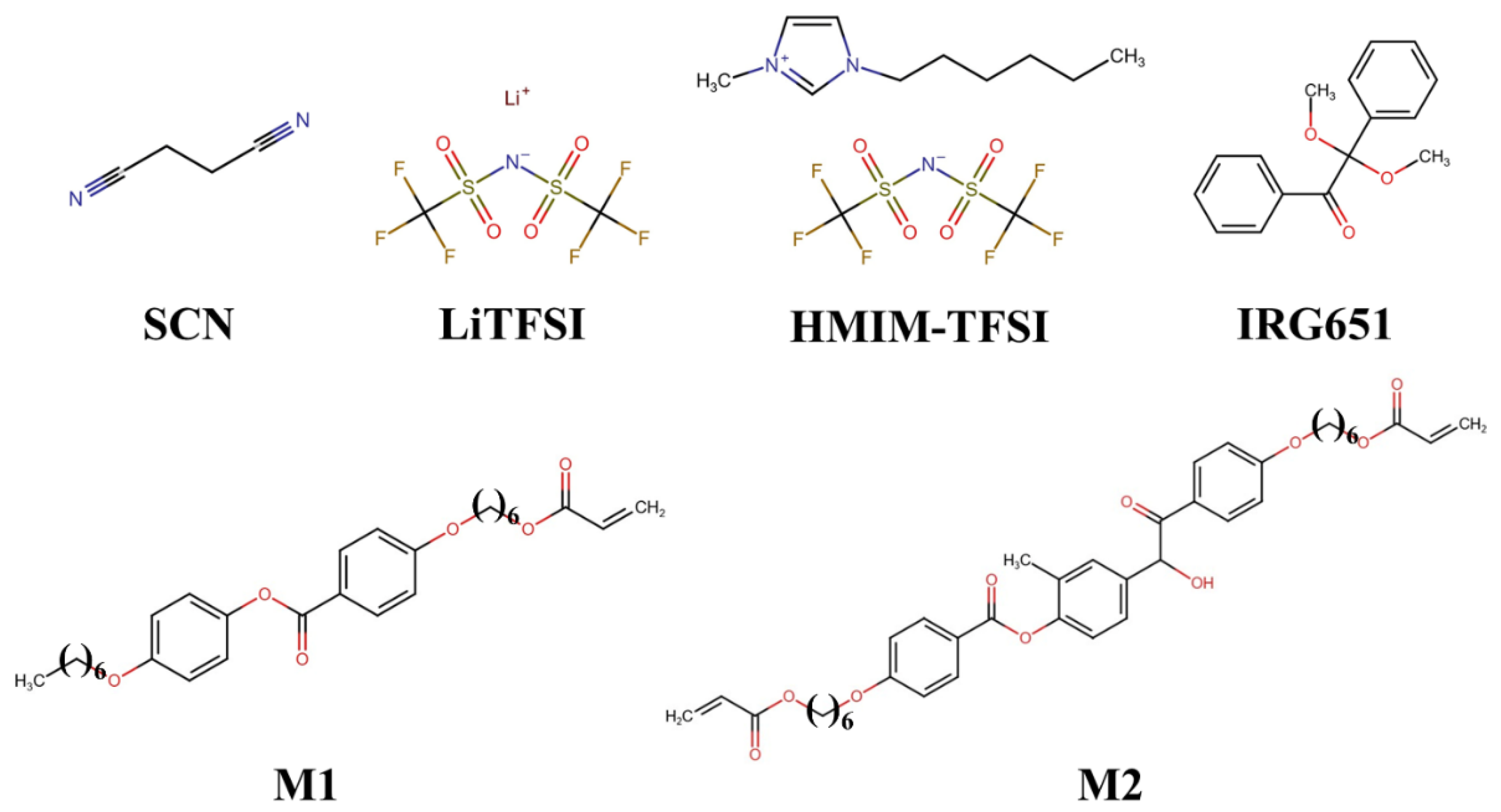
2.1. Material Composition

Monofunctional acrylate monomer 4-(6-Acryloxy-hex-1-yl-oxy) phenyl-4-(hexyloxy) benzoate (M1) and bifunctional monomer 1,4-Bis-[4-(6-acryloyloxyhexyloxy) benzoyloxy]-2-methylbenzene (M2) were purchased from Synthon chemicals. Ionic liquid 1-Hexyl-3-methylimidazolium bis(trifluormethyl sulfonyl)imide (HMIM-TFSI), photoinitiator 2,2-Dimethoxy-2-phenylacetophenone (Irgacure® 651), ionic salt lithium bis(trifluoromethyl sulfonyl)imide (LiTFSI), plasticizer succinonitrile (SCN) were acquired from Sigma-Aldrich, Milwaukee, US. Lithium metal disks (about 600 µm thick) and lithium iron phosphate (LFP) were purchased from MSE supplies (Figure 1).

2.1.1. Synthesis of Ionic Liquid Crystal Elastomer

M1, M2, and the photoinitiator were mixed in 87:12:1 weight ratio at room temperature (RT) without any solvents to form the LCE precursors (see Figure S6a), because this yielded the optimum LCE properties [49]. Subsequently, an ionic liquid (HMIM-TFSI) was added to the LCE precursor solution and mechanically stirred for 24 h using a magnetic stirrer in an Ar-filled glovebox after heating to 80 °C to achieve complete mixing. The mixture was then stored in a glass amber vial to prevent photopolymerization and kept in the glovebox at RT for future use. Figure S6 shows a synthesis route of a UV crosslinking reaction between M1 and M2 functional groups using a 1 wt% Irgacure 651 photoinitiator to obtain LCE co-networks.

2.1.2. Fabrication of iLCE Electrolyte Membrane

The binary eutectic mixture of LiTFSI and SCN, prepared at a 25:50 weight ratio, was melted at 60 °C and homogenized using a magnetic stirrer under an Ar–gas environment. Following this, the dissolved LiTFSI-SCN mixture was thoroughly combined with pre-mixed iLCE precursors at varying weight percentages and allowed to mix for 24 h. The SPE membrane based on iLCE was prepared through UV photopolymerization of iLCE, SCN, and LiTFSI. The homogeneous mixture was poured into a polytetrafluoroethylene mold with a thickness of 300 µm and a diameter of approximately 15 mm, where the solution was kept at various preset temperatures for 0.5 h. Subsequently, the electrolyte membrane was exposed to 365 nm UV light at 280 mW cm−2 intensity for 30 s at the pre-set temperatures to activate the photoinitiator to polymerize the mono- and bi-functional LCE monomers. The functional groups underwent reactions in the presence of SCN and LiTFSI at varied ratios. The curing process resulted in a binary iLCE co-network-based electrolyte membrane with a uniform film thickness of approximately 300 µm. Finally, the flexible electrolyte films were dried at RT under vacuum for 24 h. Fourier Transform Infrared Spectroscopy (FTIR) was performed on the electrolyte film and on the individual components to check the formation of fully cross-linked LCE co-networks, as shown in Figure S1.
Figure 2 shows SEM images of the electrolyte film. As SEM is carried out in a vacuum, the low-molecular-weight components (ionic liquids) are evaporated and their former places appear dark. In this way, we can obtain information about the distribution of the ionic channels that is crucial for the operation of the battery. The images in Figure 2a,c show that the ionic liquid and the polymers form a bi-continuous structure, thus allowing for an ionic pathway to form from one end to the other. The diameter of the ion channels varies from 40 µm (see Figure 2a,b) down to the 100 nm range, as seen in Figure 2d. Figure 2b illustrates the phase-separated polymer (LCE and SCN) domains. The minority component (LCE) phase separates into spherical droplets from the continuous majority component (SCN)—more evidence of this is provided by Polarized Optical Microscopy, as will be discussed in Section 2.3. Importantly, Figure 2d shows part of the minority droplet, which shows that ion channels interpenetrate even in the discontinuous minority domain.

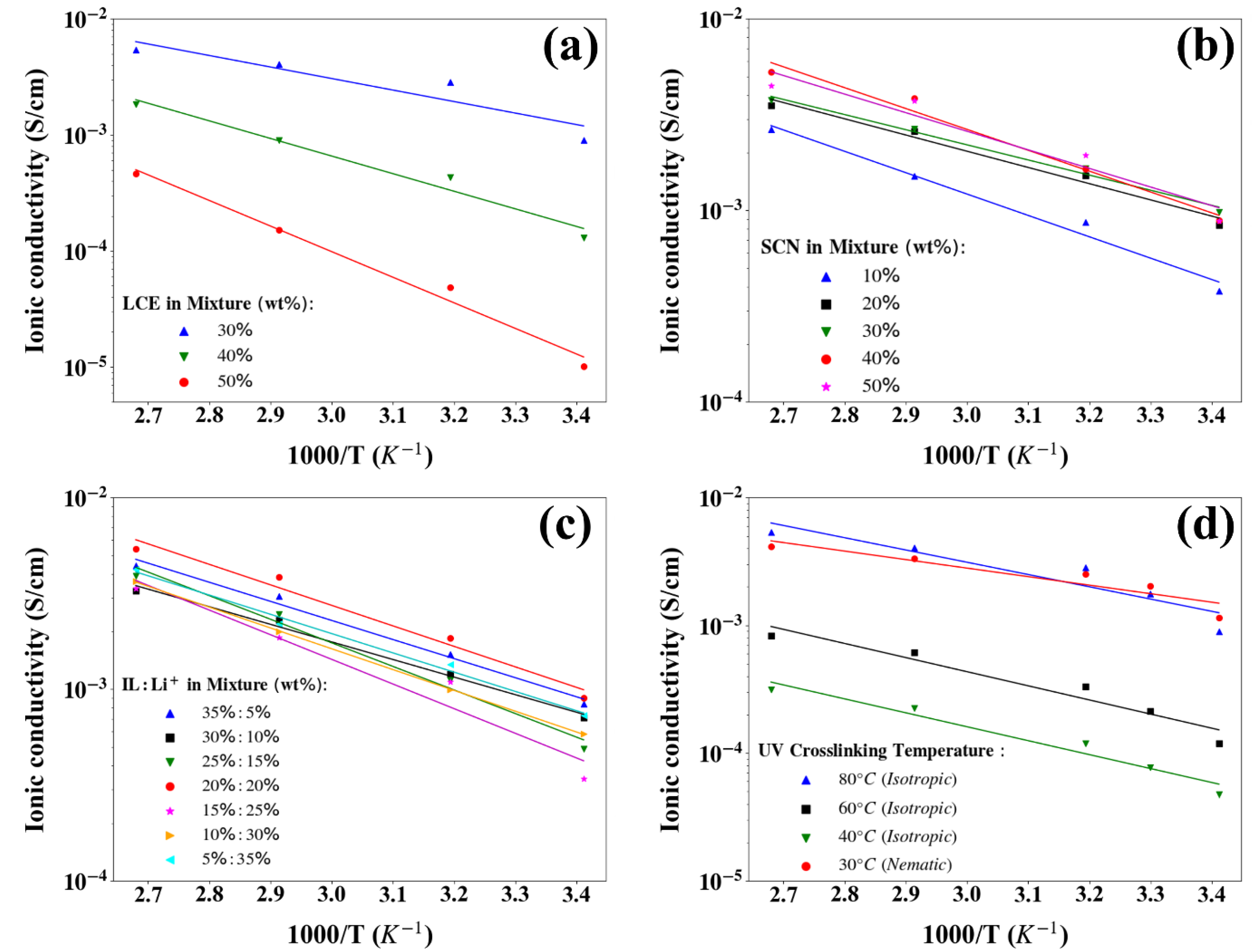
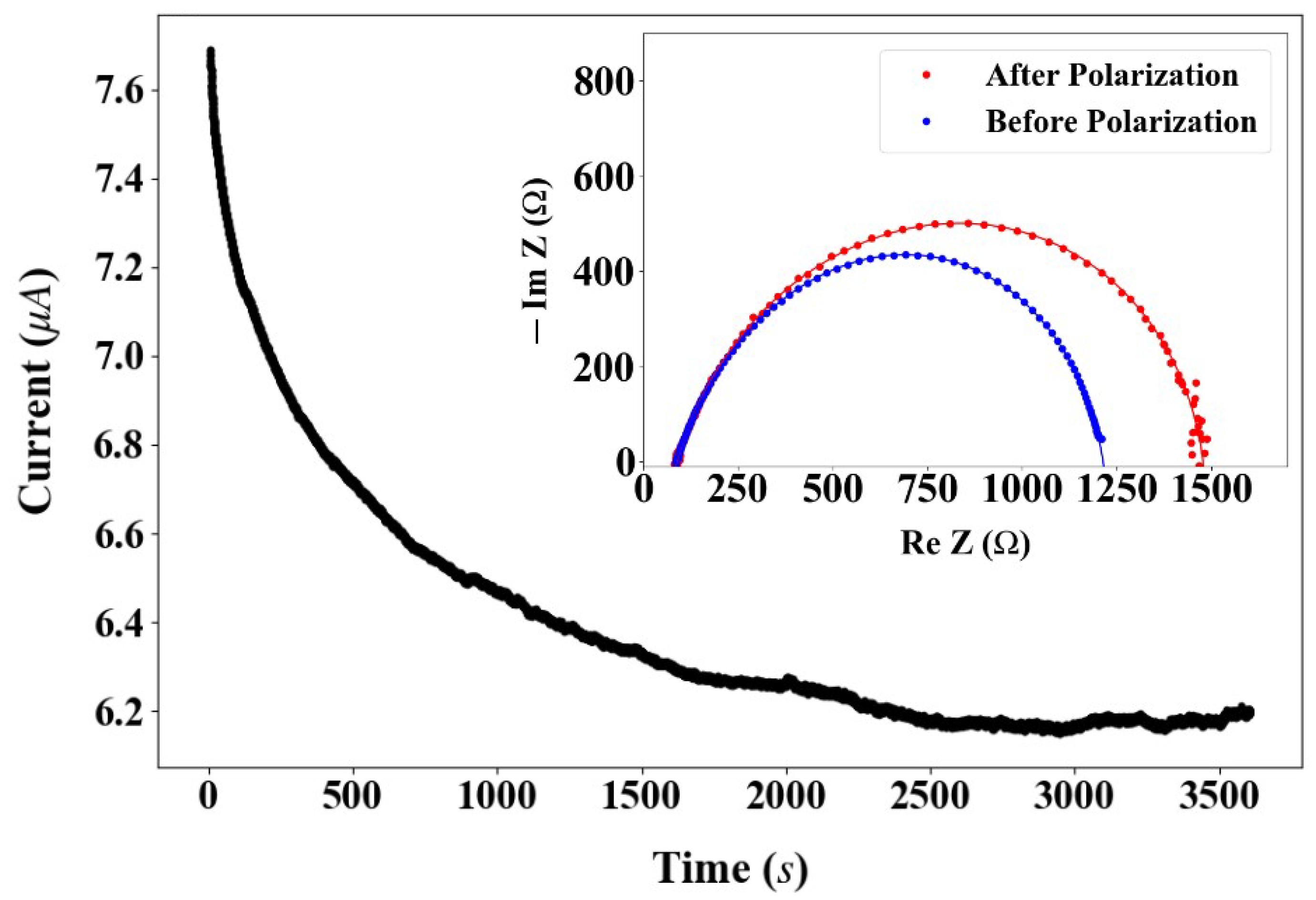
2.2. Electrochemical Performance

An impedance analysis was conducted on various PEM compositions across a temperature range of 20 °C to 100 °C. Using a custom-designed rectangular cell with precise 1 mm × 1 mm dimensions and a 0.1 mm gap, the study revealed that ionic conductivity systematically decreased with increasing temperature, closely following the Arrhenius relationship, σ T exp E a k B T , where kB = 1.38 × 10⁻²³ J K−1, T is the temperature in Kelvin scale, and E a is the activation energy. Figure 3 shows the ionic conductivity as a function of 103/T for various LCE (Figure 3a), SCN (Figure 3b), ionic liquid (IL), and Li+ ratios (Figure 3c), and at various crosslink temperatures (Figure 3d). The straight lines are the best fits corresponding to the Arrhenius behavior.
In a comparison of 30, 40, and 50% of the LCE contents (Figure 3a), one finds that the highest ionic conductivity values (9.0 × 10⁻⁴ S cm−1 at 20 °C and 5.39 × 10⁻³ S cm−1 at 90–100 °C) were found for 30% LCE. The activation energies obtained from the slopes of the best fits were 0.12, 0.27, and 0.44 eV for 30, 40, and 50% of the LCE contents, respectively. This means the material becomes increasingly solid at increasing LCE concentrations.
The study evaluated lithium-ion conduction by systematically varying the SCN content from 10 to 50 wt%, while maintaining a consistent liquid crystal elastomer composition (Figure 3b) for a comprehensive assessment of the plasticizer’s impact on ion transport properties. It was found that the ionic conductivity increased with increasing SCN concentration below 30 wt%. The increasing concentration of plasticizer improves polymer chain mobility, which facilitates enhanced ion conductivity by enabling more efficient ion transport between the anode and cathode [23,24,25]. At higher SCN concentrations, the conductivity saturates, providing about the same conductivity for the 40 and 50 wt% SCN. In accordance with the enhanced polymer chain dynamics, the activation energies decreased from 0.22 eV to 0.16 eV at plasticizer concentrations between 10% and 30%. However, at plasticizer concentrations of 40 and 50 wt%, the activation energies became higher (0.22 and 0.19 eV, respectively), indicating phase separation between the iLCE and SCN that forces SCN to ooze out onto the PEM surface. This phase separation interrupts the ion channels, leading to a slight decrease in the conductivity and an increase in the activation energy.
The effect of the ionic liquid (IL) to Li salt ratio on the ionic conductivity was investigated by comparing the 5:35, 10:30, 15:25, 20:20, 25:15, 30:10, and 35:5 IL:salt ratios so that the total weight percentage comprised 40 wt% of the total mixture, keeping the same amounts of SCN and LCE (Figure 3c). At room temperature, the ionic conductivity of the 20:20 IL-LiTFSI PEM was the largest, at 1.76 × 10⁻³ S cm−1. The activation energies were found to be 0.20, 0.18, 0.24, 0.21, 0.26, 0.22, and 0.20 eV for the 5:35, 10:30, 15:25, 20:20, 25:15, 30:10, and 35:5 IL:salt ratios, respectively.
The effect of polymerization temperature on the ionic conduction was examined by polymerization in the nematic phase of the liquid crystal at 30 °C and in the isotropic phase at 40, 60, 80 °C, during UV irradiation (Figure 3d). Comparing samples polymerized in the isotropic phase, we found that, at room temperature, the ionic conductivity increased with increasing polymerization temperatures, most likely due to the decrease in cross-link density at higher polymerization temperatures. Interestingly, the conductivity of the sample polymerized in the nematic phase was even higher than that of the PEM polymerized at 80 °C. This suggests that the elastomer network in the nematic phase forms a directional network which, in turn, acts as an ion conduction pathway for improved ion conduction. The slopes of the best fits obtained values of 0.19, 0.22, 0.22, and 0.13 eV for the samples polymerized at 30, 40, 60, and 80 °C, respectively.
Based on these findings, later experiments were focused on the LCE/HMIM-TFSI/LiTFSI/SCN: 30/17.5/17.5/35 PEM, as this showed the highest (1.76 × 10⁻³ S cm−1) ionic conductivity at RT. Its conductivity value was comparable to those of lower-end organic liquid electrolyte batteries [26,27,28]. We deliberately selected a composition with a reduced LCE content to ensure robust mechanical stability during the cell assembly process. The 30/17.5/17.5/35 polymer electrolyte membrane demonstrated a high ion transference number of 0.61 at room temperature, significantly surpassing that of organic electrolyte systems (0.22–0.35). This indicates that lithium cation transport is more prevalent than TFSI anion movement (Figure 4).
To quantify the lithium-ion transference number through our PEMs, we constructed Li/PEM/Li symmetric coin cells and conducted measurements using an Autolab PGSTAT302N galvanostat (Metrohm, Riverview, FL, USA). The experimental protocol involved applying a constant 10 mV DC bias to record both initial (I0) and steady-state (IS) current values. We systematically monitored the current response over a 3600 s interval until a stable steady-state current was achieved, enabling the precise determination of lithium-ion transport characteristics. The before (R0) and after (RS) resistances of PEMs were determined by means of an impedance analyzer in a frequency range from 1 Hz to 100 kHz. The transference number (t+) of the PEMs was calculated in accordance with equation t + = I s ( V I 0 R 0 ) I 0 ( V I S R S ) , where ΔV is the DC polarization voltage applied through the PEMs.

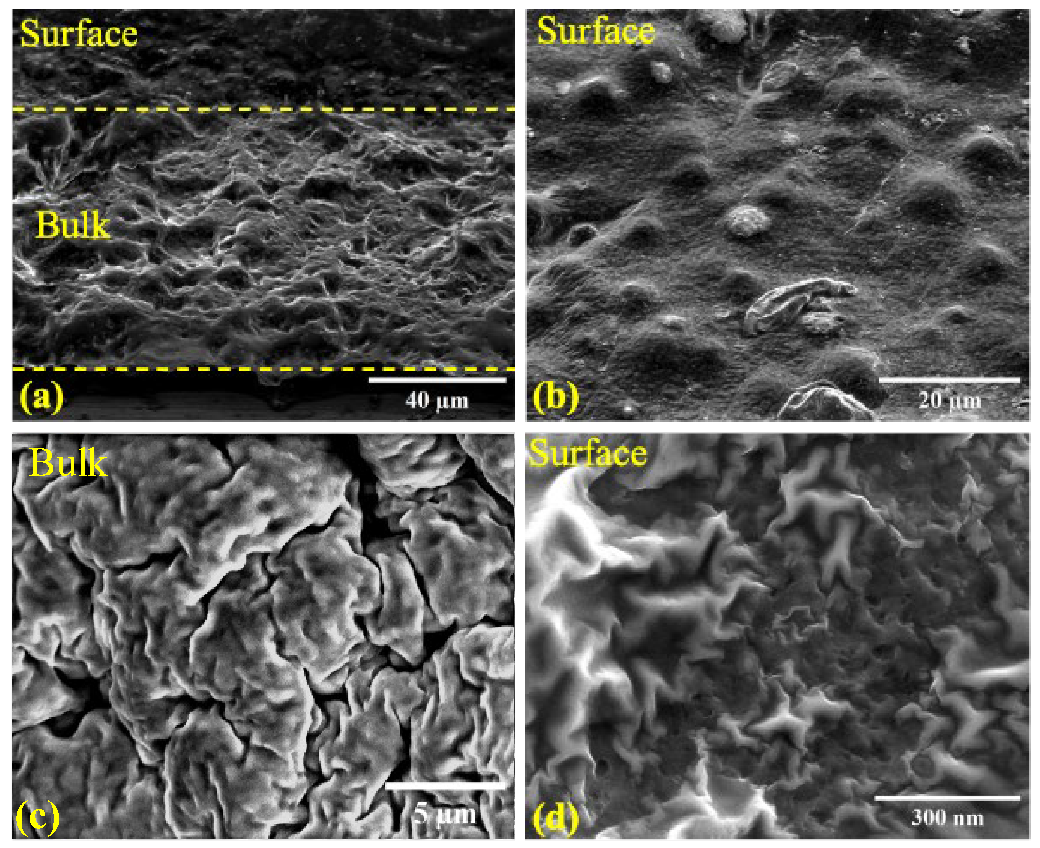
2.3. Structure of iLCE Electrolytes

Polarized Optical Microscopy (POM) studies before and after cross-linking and an inspection of the mechanical properties of the LCE/HMIM-TFSI/LiTFSI/SCN: 30/17.5/17.5/35 PEM are shown in Figure 5. The POM studies showed that the mixture before crosslinking was in an isotropic phase above 34.2 °C, with a nematic phase between 34 °C and 24 °C, and was crystalline below 24 °C. Figure 5a,b show the POM images of a 20 µm film between two bare glass plates (no rubbing) before polymerization under cross-polarizers in the isotropic (60 °C) and nematic (31 °C) phases, respectively. The isotropic structure is evidenced by the uniformly dark image. In the nematic phase, the iLC prepolymer and the SCN plasticizer phase separate and form a structure similar to polymer-dispersed nematic liquid crystals (PDLCs) [51]. The droplets exhibit four dark brushes (so-called Maltese crosses) along the cross-polarizers. indicating that the LC director orients either tangentially or radially inside the droplets [52]. Because of the radial symmetry, the optical texture remains unchanged when the sample is rotated between the crossed polarizers. After UV-induced crosslinking, the PDLC-type structure remains unchanged, although the size of the iLCE microdroplets depends on the UV intensity, polymerization time, and temperature. At 280 mW cm−2 UV intensity, applied at 60 °C for 30 s of cross-linking, the packing of iLCE droplets is quite dense, with droplet sizes of approximately 3–10 µm, as shown in Figure 5c. After polymerization, the iLCE electrolyte has a nematic phase between 34 °C and 56 °C. At higher temperatures, the droplets become isotropic, but the overall structure does not change, and upon cooling, the nematic droplets appear in their original locations. Heating above 110 °C will melt the electrolyte membrane to a liquid.
Figure 5d shows the surface structure without polarizers after a slow, low-intensity (10 mW cm−2 for 10 min) polymerization. One can see that slow polymerization causes an uneven distribution of droplet sizes and occasionally forms large domains of iLCEs in the SCN matrix. Thus, we opted for fast polymerization at high intensities. Figure 5e,f show 300 µm thick free-standing films of the 30/17.5/17.5/35 PEM at room temperature. In Figure 5e, one can see that the 300 µm thick film is self-standing and solid, while Figure 5f demonstrates that the iLCE PEM is flexible. The toughness of a 2 mm × 1 cm × 1cm (m~0.262 g) thick film was tested by hanging weights; weights of up to 60 g could be hung before it started to tear, as shown in Figure S2.

2.4. Cell Performance

To elucidate the lithium-ion storage mechanism within the PEM during the prelithiation process, we conducted a comprehensive electrochemical characterization. Specifically, we employed two analytical techniques—cyclic voltammetry (CV) and galvanostatic charge/discharge cycling—utilizing a Li metal/PEM/LiFePO4 (LFP) configuration in CR2032 coin cell format. These experiments were systematically performed across a potential range of 2.5 to 4.0 V to provide detailed insights into the membrane’s electrochemical behavior and ion transport dynamics. In the linear sweep voltammetry (LSV) scans, PEMs appeared stable against the stainless-steel (SS) electrode got up to 3.7 V (see Figure 6a), as indicated by the arrows at the onsets of the CV curves (see Figure 6b). The PEM’s stability for up to 3.75 V in the LSV data (Figure 6a) likely indicates a stability limitation, which is typical for organic and polymer electrolytes [53,54].
To investigate the oxidation and reduction peaks, a CR2032 battery cell was assembled in the Li–metal anode/SPE/LFP cathode sandwich configuration based on 30/17.5/17.5/35 LCE/HMIM-TFSI/LiTFSI/SCN PEM composition. The LFP cathode’s oxidation and reduction peaks appeared near 3.6 V–4.0 V and 3.0 V, respectively, with slight fluctuations based on the competition between in situ lithiation and capacity fading as cycling progressed (Figure 6b). CV testing was conducted in the 2.5 V–4.0 V range with the LFP cathode, where the oxidation and reduction peaks from both the Li–metal anode and PEM were observed in their corresponding potential ranges, showing a continuous increase from the second to fourth cycles. The observed increase in peak strength across cycles can be attributed to the continuous in situ lithiation during repeated cycling [55].
To validate the electrochemical durability of the PEM-based rechargeable battery, we conducted a comprehensive galvanostatic charge/discharge cycling assessment at 0.1 C rate from 3.0 V–3.7 V (Figure 7a,b). Note, XY C-Rate means X Current × Y Hours the battery can provide X current. The initial specific capacity was ~124 mAh g−1, which dropped to ~100 mAh g−1 with a capacity retention of about 80% and Coulombic efficiency of ~99%. The test was operated up to 3.7 V instead of 4.0 V to avoid overcharging the LFP cathode.
As illustrated in Figure 7c,d, the PEM demonstrated an exceptional performance across various discharge rates. At room temperature, the cell consistently delivered robust discharge capacities: 98.2 mAh g−1 at 0.1 C, 83.4 mAh g−1 at 0.2 C, 65.7 mAh g−1 at 0.5 C, and 48.8 mAh g−1 at 1 C. The charge–discharge profiles reveal remarkable reversibility, with capacities remaining remarkably consistent across different current rates, underscoring the electrolyte’s structural and electrochemical stability. Unfortunately, the cell exhibited a poor performance at higher C-rates. According to the manufacturer, the specific capacity of the LFP sheet used as the cathode is 130 mAh g−1, which is only slightly larger than the initial 124 mAh g−1 we obtained. A challenge arises due to the interaction between the nitrile groups in the SCN plasticizer and the lithium metal anode. Li0 can catalyze nitrile polymerization, leading to side reactions at the anode and potentially affecting cathodic stability [56]. Additionally, our composite electrolyte functions as a dual-ion conductor, with a non-unity transference number. This implies that lithium ions at the interface may be consumed or generated faster than they can migrate, creating a salt concentration gradient. This gradient can deplete the salt at the electrode, increasing ionic resistance, or cause salt precipitation due to enrichment. Despite this, cyclic voltammetry results and post charge–discharge analysis show minimal evidence of a salt gradient forming during operation. Based on post-cycling analysis, the iLCE-based PEM demonstrated notable electrochemical stability with minimal structural degradation. The FTIR spectra reveal shifts in Li+-oxygen coordination and S=O bond structures (see Figure S7), while POM imaging shows stress-induced planar alignment along the radial direction (see Figure S8). SEM analysis confirms the preservation of bulk material integrity, although microscopy reveals increased porosity at the anode interface (see Figures S9 and S10). These findings suggest that capacity decay at 1C is primarily attributed to ion transport limitations rather than electrolyte degradation. At a 0.1 C-rate from cycles 80 to 160, the iLCE/LiTFSI/SCN cell maintained a discharge capacity of around 98.8 mAh g−1 with nearly perfect coulombic efficiency (~99%). The flexibility of the iLCE film ensures long-term cycling stability by maintaining stable interfacial properties and ensuring excellent capacity retention at room temperature.

3. Conclusions

Our research introduces an innovative, flexible, and free-standing iLCE-based PEM developed through the in situ photopolymerization of LCE/HMIM-TFSI/LiTFSI/SCN. The PEM exhibits high ionic conductivity (1.76 × 10⁻³ S cm−1 at 30 °C), an electrochemical window of 3.7 V, and a high ionic transference number of 0.61 by constructing specialized ion-conductive channels that optimize lithium-ion mobility. When evaluated in LFP/Li battery cells, the PEM demonstrates outstanding long-term stability. Under standard testing conditions at room temperature (0.1 C-rate), the cell maintained a capacity of 98.8 mAh g−1 over 160 cycles, achieving over 80% specific capacity retention and nearly 99% coulombic efficiency. The research presents a new approach to electrolyte structures by leveraging liquid crystal elastomers rather than traditional polymer-based electrolytes. This innovation may allow for unprecedented polymer network structure control in the future through the liquid crystal director alignment parameter, shifting away from random mesh networks toward intentionally engineered structures. The iLCE offers multiple advantages: its rubbery nature prevents dendritic growth in electrodes, its thermal shrinkage characteristics reduce heating-related pressure commonly found in liquid lithium-ion batteries [50], and its straightforward fabrication process enhances its practical application. This pioneering study demonstrates the first and most promising implementation of a room-temperature SSPLIB using an iLCE-based PEM, successfully combining high capacity with enhanced safety features. Subsequent research will explore how alignment effects in iLCE-based solid electrolytes can further improve performance.
As we were preparing our work for submission, we became aware of a study by Wang et al. utilizing LCE in batteries [57]. Their electrolyte exhibited a room-temperature conductivity comparable to ours at 2 mS cm−1. However, while they employed RM257 as the sole LC mesogenic unit, our approach incorporated both mono- and bi-functional mesogenic units, M1 and M2, respectively. Additionally, unlike our study, their formulation did not include plasticizers. Structurally, our LC formed nematic droplets, whereas theirs resulted in a polydomain LC film. While conducting cyclic voltammetry, our electrochemical analysis revealed distinct oxidation and reduction peaks that differed slightly from their findings. Specifically, their measurements indicated oxidation and reduction peaks at 4.03 V and 3.20 V, respectively, whereas our experimental results showed peaks at around 3.75 V and 3.04 V. The transference number across their various samples ranged from 0.57 to 0.72, while our system exhibited a value of 0.61. Regarding battery performance, a key distinction between our work and that of Wang et al. lies in the number of oxygen sites in the polymer chains. In polymer electrolytes, ion-hopping is a primary mode of ion transport, which relies on oxygen sites [58,59]. Notably, lithium binding to oxygen in the polymer electrolyte membrane (PEM) may enhance the overall capacity beyond the theoretical maximum of the cathode’s active material [60]. The study by Wang et al. [57] incorporated carbon-based additives such as the use of PVDF as a binder and acetylene black, whereas our cathode was purely LiFePO4 (LFP)-based, explaining the specific capacity disparity between our systems aside from different the types of ionic liquid cation interaction with Li-salt.

4. Patents

A Utility—Provisional Application under 35 USC 111(b) entitled “Solid State Battery Including Ionic Liquid Crystal Elastomers” was filed by Zakaria Siddiquee, Hyunsang Lee, Weinan Xu, Thein Kyu and Antal Jákli on 10 October 2024 by Application #: 63/705,869, Attorney Docket #: KSU.605.PRV.

Supplementary Materials

The following supporting information can be downloaded at: https://www.mdpi.com/article/10.3390/batteries11030106/s1, Figure S1: Fourier Transform Infrared Spectroscopy (FTIR) performed on electrolyte film and individual components. (a) FTIR spectra of LCE precursor, HMIM-TFSi, LiTFSi, SCN and polymerized PEM between 4000 and 400 cm-1, (b) FTIR spectra of M1, M2, LCE before and after crosslinking between 4000 and 400 cm-1, (c) C=C symmetric and/or asymmetric stretching vibration peaks from PEM between 1640 and 1610 cm-1, and (d) C=C twisting from 810 cm-1 attributable to the C=C double bonds before (black) and after (blue) UV cross-linking under uniform UV exposure at 365 nm for 30 s.; Figure S2: Stretch test of 2 mm × 10 mm × 10 mm PEM under 0.5 N force (the weight of 50 g mass); Figure S3: POM images of SCN/LCE/SCN sandwich cells. (a) Empty-cell under crossed polarizers, and (b) Filled-cell under crossed polarizers; Figure S4: Image of solid state CR2032 lithium coin cells based on iLCE powering two blue LEDs (a), 1.5V generic calculator (b) and 1.5V digital stopwatch by Fisher Scientific (c); Figure S5: Possible lithium-ion transport pathways in composite polymer electrolyte; Figure S6: Schematic structure of LCE and SCN in PEM electrolyte. (a) LCE is made of crosslinked network of main chains formed by M2 monomer and side chains formed by M1 and M2. (b) An example of a molecular unit cell configuration of SCN; Figure S7: FTIR spectra of the iLCE-based PEM before and after charge-discharge cycling with distinct peaks associated with Li+ and TFSI- ions contributions to vibrational bands; Figure S8: POM images of the iLCE post charge-discharge cycling under crossed polarizers. (a), (c) iLCE is bright at 45° and 135° with respect to the polarizer and (b), (d) iLCE is dark at 0° and 90° with respect to the polarizer; Figure S9: SEM images of a 45° tilted cross-section of iLCE post charge-discharge cycle. (a) Cutoff point at the surface of the PEM, (b) the bulk of the electrolyte, and (c) the interface between bulk and the LFP cathode; Figure S10: Microscope images iLCE surface on the anode side post charge-discharge cycle, (a) near the center of the PEM, and (b) near the edge. References [56,58,59,61,62,63] are cited in Supplementary Materials.

Author Contributions

Conceptualization, A.J.; methodology, T.K. and W.X.; validation, Z.S. and H.L.; formal analysis, Z.S.; investigation, Z.S.; resources, T.K., W.X. and A.J.; data curation, Z.S. and H.L.; writing—original draft preparation, Z.S.; writing—review and editing, A.J., T.K. and W.X.; supervision, A.J. All authors have read and agreed to the published version of the manuscript.

Funding

This research received no external funding.

Data Availability Statement

The data that support the findings of this study are available from the corresponding author upon reasonable request.

Acknowledgments

Z.S. and A.J. acknowledge useful discussions with Paul Rajib.

Conflicts of Interest

The authors declare no conflicts of interest.

References

  1. Walker, C.W.; Cox, J.D.; Salomon, M. Conductivity and Electrochemical Stability of Electrolytes Containing Organic Solvent Mixtures with Lithium Tris(Trifluoromethanesulfonyl)Methide. J. Electrochem. Soc. 1996, 143, L80–L82. [Google Scholar] [CrossRef]
  2. Armand, M. The History of Polymer Electrolytes. Solid State Ion. 1994, 69, 309–319. [Google Scholar] [CrossRef]
  3. Goodenough, J.B.; Kim, Y. Challenges for Rechargeable Li Batteries. Chem. Mater. 2010, 22, 587–603. [Google Scholar] [CrossRef]
  4. Etacheri, V.; Marom, R.; Elazari, R.; Salitra, G.; Aurbach, D. Challenges in the Development of Advanced Li-Ion Batteries: A Review. Energy Environ. Sci. 2011, 4, 3243–3262. [Google Scholar] [CrossRef]
  5. Tarascon, J.M.; Armand, M. Issues and Challenges Facing Rechargeable Lithium Batteries. Nature 2001, 414, 359–367. [Google Scholar] [CrossRef]
  6. Nair, J.R.; Imholt, L.; Brunklaus, G.; Winter, M. Lithium Metal Polymer Electrolyte Batteries: Opportunities and Challenges. Electrochem. Soc. Interface 2019, 28, 55–61. [Google Scholar] [CrossRef]
  7. Deng, K.; Qin, J.; Wang, S.; Ren, S.; Han, D.; Xiao, M.; Meng, Y. Effective Suppression of Lithium Dendrite Growth Using a Flexible Single-Ion Conducting Polymer Electrolyte. Small 2018, 14, 1801420. [Google Scholar] [CrossRef]
  8. Zhang, H.; Li, C.; Piszcz, M.; Coya, E.; Rojo, T.; Rodriguez-Martinez, L.M.; Armand, M.; Zhou, Z. Single Lithium-Ion Conducting Solid Polymer Electrolytes: Advances and Perspectives. Chem. Soc. Rev. 2017, 46, 797–815. [Google Scholar] [CrossRef]
  9. Nakayama, M.; Wada, S.; Kuroki, S.; Nogami, M. Factors Affecting Cyclic Durability of All-Solid-State Lithium Polymer Batteries Using Poly(Ethylene Oxide)-Based Solid Polymer Electrolytes. Energy Environ. Sci. 2010, 3, 1995–2002. [Google Scholar] [CrossRef]
  10. Fergus, J.W. Ceramic and Polymeric Solid Electrolytes for Lithium-Ion Batteries. J. Power Sources 2010, 195, 4554–5469. [Google Scholar] [CrossRef]
  11. Yu, X.; Manthiram, A. A Review of Composite Polymer-Ceramic Electrolytes for Lithium Batteries. Energy Storage Mater. 2021, 34, 282–300. [Google Scholar] [CrossRef]
  12. Li, S.; Zhang, S.Q.; Shen, L.; Liu, Q.; Ma, J.B.; Lv, W.; He, Y.B.; Yang, Q.H. Progress and Perspective of Ceramic/Polymer Composite Solid Electrolytes for Lithium Batteries. Adv. Sci. 2020, 7, 1903088. [Google Scholar] [CrossRef] [PubMed]
  13. Chung, S.H.; Wang, Y.; Persi, L.; Croce, F.; Greenbaum, S.G.; Scrosati, B.; Plichta, E. Enhancement of Ion Transport in Polymer Electrolytes by Addition of Nanoscale Inorganic Oxides. J. Power Sources 2001, 97–98, 644–648. [Google Scholar] [CrossRef]
  14. Takeda, Y.; Yamamoto, O.; Imanishi, N. Lithium Dendrite Formation on a Lithium Metal Anode from Liquid, Polymer and Solid Electrolytes. Electrochemistry 2016, 84, 210–218. [Google Scholar] [CrossRef]
  15. Wang, D.; Zhang, W.; Zheng, W.; Cui, X.; Rojo, T.; Zhang, Q. Towards High-Safe Lithium Metal Anodes: Suppressing Lithium Dendrites via Tuning Surface Energy. Adv. Sci. 2017, 4, 1600168. [Google Scholar] [CrossRef] [PubMed]
  16. Mandal, M.; Bardhan, P.; Mandal, M.; Maji, T.K. Development of Wood Polymer Composites with Thermosetting Resin from Soybean Oil Cross-Linked with Rosin Derivative. Eur. J. Wood Wood Prod. 2020, 78, 1265–1278. [Google Scholar] [CrossRef]
  17. Goydaragh, M.G.; Taghizadeh-Mehrjardi, R.; Jafarzadeh, A.A.; Triantafilis, J.; Lado, M. Using Environmental Variables and Fourier Transform Infrared Spectroscopy to Predict Soil Organic Carbon. Catena 2021, 202, 105280. [Google Scholar] [CrossRef]
  18. Ehgartner, C.R.; Werner, V.; Selz, S.; Hüsing, N.; Feinle, A. Carboxylic Acid-Modified Polysilsesquioxane Aerogels for the Selective and Reversible Complexation of Heavy Metals and Organic Molecules. Microporous Mesoporous Mater. 2021, 312, 110759. [Google Scholar] [CrossRef]
  19. Evans, J.; Vincent, C.A.; Bruce, P.G. Electrochemical Measurement of Transference Numbers in Polymer Electrolytes. Polymer 1987, 28, 2324–2328. [Google Scholar] [CrossRef]
  20. Goodenough, J.B.; Park, K.S. The Li-Ion Rechargeable Battery: A Perspective. J. Am. Chem. Soc. 2013, 135, 1167–1176. [Google Scholar] [CrossRef]
  21. Tatsumisago, M.; Nagao, M.; Hayashi, A. Recent Development of Sulfide Solid Electrolytes and Interfacial Modification for All-Solid-State Rechargeable Lithium Batteries. J. Asian Ceram. Soc. 2013, 1, 17–25. [Google Scholar] [CrossRef]
  22. Kaneko, F.; Wada, S.; Nakayama, M.; Wakihara, M.; Koki, J.; Kuroki, S. Capacity Fading Mechanism in All Solid-State Lithium Polymer Secondary Batteries Using PEG-Borate/Alumlnate Ester as Plasticizer for Polymer Electrolytes. Adv. Funct. Mater. 2009, 19, 918–925. [Google Scholar] [CrossRef]
  23. Bruce, P.G.; Evans, J.; Vincent, C.A. Conductivity and Transference Number Measurements on Polymer Electrolytes. Solid State Ion. 1988, 28–30, 918–922. [Google Scholar] [CrossRef]
  24. Strickberger, S.A.; Ravi, S.; Daoud, E.; Niebauer, M.; Man, K.C.; Morady, F. Relation between Impedance and Temperature during Radiofrequency Ablation of Accessory Pathways. Am. Heart J. 1995, 130, 1026–1030. [Google Scholar] [CrossRef]
  25. Feng, C.; Kyu, T. Role of Dinitrile Plasticizer Chain Lengths in Electrochemical Performance of Highly Conductive Polymer Electrolyte Membrane for Lithium Ion Battery. Electrochim. Acta 2020, 330, 135320. [Google Scholar] [CrossRef]
  26. Pal, U.; Chen, F.; Gyabang, D.; Pathirana, T.; Roy, B.; Kerr, R.; MacFarlane, D.R.; Armand, M.; Howlett, P.C.; Forsyth, M. Enhanced Ion Transport in an Ether Aided Super Concentrated Ionic Liquid Electrolyte for Long-Life Practical Lithium Metal Battery Applications. J. Mater. Chem. A Mater. 2020, 8, 18826–18839. [Google Scholar] [CrossRef]
  27. Chang, Z.; Qiao, Y.; Deng, H.; Yang, H.; He, P.; Zhou, H. A Liquid Electrolyte with De-Solvated Lithium Ions for Lithium-Metal Battery. Joule 2020, 4, 1776–1789. [Google Scholar] [CrossRef]
  28. Sun, H.; Zhu, G.; Zhu, Y.; Lin, M.C.; Chen, H.; Li, Y.Y.; Hung, W.H.; Zhou, B.; Wang, X.; Bai, Y.; et al. High-Safety and High-Energy-Density Lithium Metal Batteries in a Novel Ionic-Liquid Electrolyte. Adv. Mater. 2020, 32, 2001741. [Google Scholar] [CrossRef]
  29. Kobayashi, K.; Pagot, G.; Vezzù, K.; Bertasi, F.; Di Noto, V.; Tominaga, Y. Effect of Plasticizer on the Ion-Conductive and Dielectric Behavior of Poly(Ethylene Carbonate)-Based Li Electrolytes. Polym. J. 2021, 53, 149–155. [Google Scholar] [CrossRef]
  30. Wang, B.; Wu, Y.; Zhuo, S.; Zhu, S.; Chen, Y.; Jiang, C.; Wang, C. Synergistic Effect of Organic Plasticizer and Lepidolite Filler on Polymer Electrolytes for All-Solid High-Voltage Li-Metal Batteries. J. Mater. Chem. A Mater. 2020, 8, 5968–5974. [Google Scholar] [CrossRef]
  31. Rosero-Navarro, N.C.; Kajiura, R.; Miura, A.; Tadanaga, K. Organic−inorganic Hybrid Materials for Interface Design in All-Solid-State Batteries with a Garnet-Type Solid Electrolyte. ACS Appl. Energy Mater. 2020, 3, 11260–11268. [Google Scholar] [CrossRef]
  32. Ibrahim, S.; Johan, M.R. Conductivity, Thermal and Neural Network Model Nanocomposite Solid Polymer Electrolyte System (PEO-LiPF 6-EC-CNT). Int. J. Electrochem. Sci. 2011, 6, 5565–5587. [Google Scholar] [CrossRef]
  33. Klongkan, S.; Pumchusak, J. Effects of Nano Alumina and Plasticizers on Morphology, Ionic Conductivity, Thermal and Mechanical Properties of PEO-LiCF3SO3 Solid Polymer Electrolyte. Electrochim. Acta 2015, 161, 171–176. [Google Scholar] [CrossRef]
  34. Christie, A.M.; Lilley, S.J.; Staunton, E.; Andreev, Y.G.; Bruce, P.G. Increasing the Conductivity of Crystalline Polymer Electrolytes. Nature 2005, 433, 50–53. [Google Scholar] [CrossRef]
  35. Phan, T.N.T.; Issa, S.; Gigmes, D. Poly(Ethylene Oxide)-Based Block Copolymer Electrolytes for Lithium Metal Batteries. Polym. Int. 2019, 68, 7–13. [Google Scholar] [CrossRef]
  36. Young, W.S.; Epps, T.H. Ionic Conductivities of Block Copolymer Electrolytes with Various Conducting Pathways: Sample Preparation and Processing Considerations. Macromolecules 2012, 45, 4689–4697. [Google Scholar] [CrossRef]
  37. Ben youcef, H.; Garcia-Calvo, O.; Lago, N.; Devaraj, S.; Armand, M. Cross-Linked Solid Polymer Electrolyte for All-Solid-State Rechargeable Lithium Batteries. Electrochim. Acta 2016, 220, 587–594. [Google Scholar] [CrossRef]
  38. Stalin, S.; Choudhury, S.; Zhang, K.; Archer, L.A. Multifunctional Cross-Linked Polymeric Membranes for Safe, High-Performance Lithium Batteries. Chem. Mater. 2018, 30, 2058–2066. [Google Scholar] [CrossRef]
  39. Schulze, M.W.; McIntosh, L.D.; Hillmyer, M.A.; Lodge, T.P. High-Modulus, High-Conductivity Nanostructured Polymer Electrolyte Membranes via Polymerization-Induced Phase Separation. Nano Lett. 2014, 14, 122–126. [Google Scholar] [CrossRef]
  40. Yang, L.; Wang, Z.; Feng, Y.; Tan, R.; Zuo, Y.; Gao, R.; Zhao, Y.; Han, L.; Wang, Z.; Pan, F. Flexible Composite Solid Electrolyte Facilitating Highly Stable “Soft Contacting” Li–Electrolyte Interface for Solid State Lithium-Ion Batteries. Adv. Energy Mater. 2017, 7, 1701437. [Google Scholar] [CrossRef]
  41. Bhattacharyya, A.J.; Fleig, J.; Guo, Y.G.; Maier, J. Local Conductivity Effects in Polymer Electrolytes. Adv. Mater. 2005, 17, 2630–2634. [Google Scholar] [CrossRef]
  42. Yoshio, M.; Mukai, T.; Ohno, H.; Kato, T. One-Dimensional Ion Transport in Self-Organized Columnar Ionic Liquids. J. Am. Chem. Soc. 2004, 126, 994–995. [Google Scholar] [CrossRef]
  43. Yamanaka, N.; Kawano, R.; Kubo, W.; Kitamura, T.; Wada, Y.; Watanabe, M.; Yanagida, S. Ionic Liquid Crystal as a Hole Transport Layer of Dye-Sensitized Solar Cells. Chem. Commun. 2005, 6, 740–742. [Google Scholar] [CrossRef]
  44. Lee, S.; Becht, G.A.; Lee, B.; Burns, C.T.; Firestone, M.A. Electropolymerization of a Bifunctional Ionic Liquid Monomer Yields an Electroactive Liquid-Crystalline Polymer. Adv. Funct. Mater. 2010, 20, 2063–2070. [Google Scholar] [CrossRef]
  45. Wang, S.; Liu, X.; Wang, A.; Wang, Z.; Chen, J.; Zeng, Q.; Wang, X.; Zhang, L. An Ionic Liquid Crystal-Based Solid Polymer Electrolyte with Desirable Ion-Conducting Channels for Superior Performance Ambient-Temperature Lithium Batteries. Polym. Chem. 2018, 9, 4674–4682. [Google Scholar] [CrossRef]
  46. Mukai, T.; Yoshio, M.; Kato, T.; Yoshizawa, M.; Ohno, H. Anisotropic Ion Conduction in a Unique Smectic Phase of Self-Assembled Amphiphilic Ionic Liquids. Chem. Commun. 2005, 10, 1333–1335. [Google Scholar] [CrossRef] [PubMed]
  47. Uchida, Y.; Matsumoto, T.; Akita, T.; Nishiyama, N. Ion Conductive Properties in Ionic Liquid Crystalline Phases Confined in a Porous Membrane. J. Mater. Chem. C Mater. 2015, 3, 6144–6147. [Google Scholar] [CrossRef]
  48. Kuo, D.; Soberats, B.; Kumar, K.R.S.; Yoshio, M.; Ichikawa, T.; Ohno, H.; Zeng, X.; Ungar, G.; Kato, T. Switching of Ionic Conductivities in Columnar Liquid-Crystalline Anilinium Salts: Effects of Alkyl Chains, Ammonium Cations and Counter Anions on Thermal Properties and Switching Temperatures. Mol. Syst. Des. Eng. 2019, 4, 342–347. [Google Scholar] [CrossRef]
  49. Alyami, A.; Rajapaksha, C.P.H.; Feng, C.; Paudel, P.R.; Paul, A.; Adaka, A.; Dharmarathna, R.; Lüssem, B.; Jákli, A. Ionic Liquid Crystal Elastomers for Actuators, Sensors, and Organic Transistors. Liq. Cryst. 2023, 50, 1151–1161. [Google Scholar] [CrossRef]
  50. Luo, S.C.; Sun, S.; Deorukhkar, A.R.; Lu, J.T.; Bhattacharyya, A.; Lin, I.J.B. Ionic Liquids and Ionic Liquid Crystals of Vinyl Functionalized Imidazolium Salts. J. Mater. Chem. 2011, 21, 1866–1873. [Google Scholar] [CrossRef]
  51. Drzaic, P.S. Liquid Crystal Dispersions; World Scientific: River Edge, NJ, USA, 1995. [Google Scholar]
  52. Scharf, T. Polarized Light in Liquid Crystals and Polymers; Wiley: Hoboken, NJ, USA, 2006. [Google Scholar]
  53. Méry, A.; Rousselot, S.; Lepage, D.; Dollé, M. A Critical Review for an Accurate Electrochemical Stability Window Measurement of Solid Polymer and Composite Electrolytes. Materials 2021, 14, 3840. [Google Scholar] [CrossRef] [PubMed]
  54. Seidl, L.; Grissa, R.; Zhang, L.; Trabesinger, S.; Battaglia, C. Unraveling the Voltage-Dependent Oxidation Mechanisms of Poly(Ethylene Oxide)-Based Solid Electrolytes for Solid-State Batteries. Adv. Mater. Interfaces 2022, 9, 2100704. [Google Scholar] [CrossRef]
  55. Lee, H.; Jeong, J.; Parrondo, J.; Zamani, S.; Atienza, D.; Kyu, T. Enhanced Energy Storage in Lithium-Metal Batteries via Polymer Electrolyte Polysulfide-Polyoxide Conetworks. ACS Appl. Mater. Interfaces 2023, 15, 27173–27182. [Google Scholar] [CrossRef] [PubMed]
  56. Alarco, P.J.; Abu-Lebdeh, Y.; Abouimrane, A.; Armand, M. The Plastic-Crystalline Phase of Succinonitrile as a Universal Matrix for Solid-State Ionic Conductors. Nat. Mater. 2004, 3, 476–481. [Google Scholar] [CrossRef]
  57. Wang, X.; He, Z.; Yan, R.; Niu, H.; He, W.; Miao, Z. Liquid Crystal Elastomer-Based Solid Electrolyte with Intelligently Regulated Rigidity–Flexibility toward High-Energy Lithium Batteries. Chem. Eng. J. 2025, 503, 158552. [Google Scholar] [CrossRef]
  58. Fu, J.; Li, Z.; Zhou, X.; Guo, X. Ion Transport in Composite Polymer Electrolytes. Mater. Adv. 2022, 3, 3809–3819. [Google Scholar] [CrossRef]
  59. Gerdroodbar, A.E.; Alihemmati, H.; Safavi-Mirmahaleh, S.A.; Golshan, M.; Damircheli, R.; Eliseeva, S.N.; Salami-Kalajahi, M. A Review on Ion Transport Pathways and Coordination Chemistry between Ions and Electrolytes in Energy Storage Devices. J. Energy Storage 2023, 74, 109311. [Google Scholar] [CrossRef]
  60. Lee, H.; Choi, J.W.; Kyu, T. A Comparative Study on Electrochemical Performance of Single versus Dual Networks in Lithium Metal/Polysulfide-Polyoxide Co-Network/Lithium Titanium Oxide Cathode. Batteries 2024, 10, 163. [Google Scholar] [CrossRef]
  61. Xue, Z.; He, D.; Xie, X. Poly(Ethylene Oxide)-Based Electrolytes for Lithium-Ion Batteries. J. Mater. Chem. A Mater. 2015, 3, 19218–19253. [Google Scholar] [CrossRef]
  62. Derollez, P.; Lefebvre, J.; Descamps, M.; Press, W.; Fontaine, H. Structure of Succinonitrile in Its Plastic Phase. J. Phys. Condens. Matter 1990, 2, 6893. [Google Scholar] [CrossRef]
  63. Yang, H.; Wu, N. Ionic Conductivity and Ion Transport Mechanisms of Solid-State Lithium-Ion Battery Electrolytes: A Review. Energy Sci. Eng. 2022, 10, 1643–1671. [Google Scholar] [CrossRef]
Figure 1. The molecular structures of the components of the studied PEM: M1 and M2 are mesogenic units. HMIM-TFSI is the ionic liquid; Irgacure 651 is the photoinitiator; SCN is the plasticizer; LiTFSI is the ionic salt.
Batteries 11 00106 g001
Figure 2. SEM images of the iLCE SPE. (a) Electrolyte cross-section tilted at 45°; (b) surface image; (c) bulk image at electrolyte cross-section; (d) zoomed-in texture on the surface of the liquid crystal droplet.
Batteries 11 00106 g002
Figure 3. Arrhenius plots of ionic conductivity (logarithmic conductivity versus 1000/T). (a) For different ratios of LCE in electrolyte mixture; (b) for different ratios of SCN in electrolyte mixture; (c) for different ratios of HMIM-TFSI and LiTFSI in electrolyte mixture; and (d) for different crosslinking temperatures of PEM.
Batteries 11 00106 g003
Figure 4. Room-temperature chronoamperometry of a symmetric (Li-PEM-Li) cell in response to a UDC = 0.01 V bias for the LCE/HMIM-TFSI/LiTFSI/SCN:30/17.5/17.5/35 PEM. The accompanying inset displays the impedance Nyquist plot of the PEM, comparing its initial state with the configuration after achieving steady-state current conditions.
Batteries 11 00106 g004
Figure 5. Polarized Optical Microscopy (POM) studies before (a,b) and after (c) cross-linking; microscopy image of the surface after (d) cross-linking and inspection of mechanical properties (e,f) of the 30/17.5/17.5/35 PEM after cooling at 0.1 °C min1 rate. (a) POM image in the isotropic phase at 60 °C; (b) nematic droplets at 31 °C. (c) Nematic elastomer droplets after crosslinking at 280 mW cm2 UV intensity at 80 °C for 30 s; (d) surface images of nematic elastomer droplets after crosslinking at 10 mW cm2 for 10   m i n between parallel polarizers; (e) self-standing 300 µm thick film; (f) demonstration of the flexibility of the iLCE PEM film. Arrows indicate the directions of the crossed polarizers.
Batteries 11 00106 g005
Figure 6. Summary of voltammetry results with a potential scan rate of 5 mV s1. (a) Linear sweep voltammogram of PEM at 24 °C; (b) cyclic voltammetry test of the Li/SPE/LFP configuration in cathode range (2.5–4.0 V) at 24 °C. The arrows indicate the approximate locations of the oxidation and reduction peak voltages.
Batteries 11 00106 g006
Figure 7. Charge and discharge cycling characteristics of the iLCE-based PEM in a coin cell battery. (a) Specific capacity and coulombic efficiency over 160 charge and discharge cycles; (b) charge and discharge profiles for Li/SPE/LFP cathode cells with a cathode range of 3.0–3.7V at a C-rate of 0.1 at 25 °C, where the arrow indicates reduction of specific capacity with cycling; (c) charge/discharge curves of Li/SPE/LFP cell at different C-rates after 100 cycles; (d) the cycle performance of the Li/SPE/LFP battery during galvanostatic cycling at 0.1, 0.2, 0.5, and 1 C-rates.
Batteries 11 00106 g007
Disclaimer/Publisher’s Note: The statements, opinions and data contained in all publications are solely those of the individual author(s) and contributor(s) and not of MDPI and/or the editor(s). MDPI and/or the editor(s) disclaim responsibility for any injury to people or property resulting from any ideas, methods, instructions or products referred to in the content.

