1. Introduction
The convergence of advancements in lithium-ion battery technology, battery management systems (BMSs) and thermal management solutions represents a paradigm shift in sustainable transportation [
1]. As electric vehicles (EVs) continue to gain traction, optimizing battery performance, safety and longevity will remain at the forefront of research and innovation. Advanced numerical modeling techniques for modeling the battery parameters and developing battery management algorithms hold great promise for greener, cleaner and more efficient future mobility solutions.
In the realm of sustainable transportation and energy conservation, the advancement of EV technologies is fundamental to reduce the environmental impact and dependency on fossil fuels. Among the critical components of EV operation and efficiency, lithium-ion batteries (LiBs) stand out due to their unparalleled performance characteristics. They are valued for their high energy density, long service life and excellent energy efficiency. To realize the full potential of LiBs, advanced BMSs are essential [
2]. These systems act as the nerve center of lithium-ion battery packs, ensuring safe and efficient operation while optimizing performance for a longer service life.
However, the thermal management of LiBs poses a significant challenge, especially in EVs. An efficient battery thermal management system (BTMS) is required for ensuring the longevity of LiBs by optimizing the operating temperatures and reducing the risk of thermal runaway [
3]. BTMSs maintain battery operation within safe limits, extending battery life and improving the overall safety of the vehicle [
4].
Among the various BTMS solutions, air-based systems have attracted widespread attention due to their adaptability and reliability [
5]. Air-cooled BTMSs offer an attractive proposition for EV manufacturers seeking to balance performance, efficiency and safety. Understanding the thermal behavior of LiBs is critical to ensure their performance and safety [
6]. While experimental approaches provide insight into battery operation, they are often limited by time, effort and accessibility limitations. In contrast, numerical simulations offer a versatile and flexible means to comprehensively investigate battery operation under a variety of conditions for design optimization and performance enhancement [
7]. These simulations also allow for validation using different verification protocols like SIL, MIL and HIL for industrial production.
Among the different types of numerical characterization techniques for battery modeling, equivalent circuit models (ECMs) stand out as essential tools for understanding and modeling the non-linear electro-thermal behavior of LiBs [
8]. ECMs simplify complex electrochemical processes within batteries, making it easier to accurately estimate critical battery parameters [
9]. These models provide a structured framework for analyzing battery dynamics and optimizing automotive BMS accordingly.
The state of charge (SOC) is a critical parameter for battery management, and other battery parameters, such as the state of health (SOH), state of power (SOP) and state of energy (SOE), are essential for optimizing cell performance and ensuring the reliability of the battery pack [
10]. However, the non-linear and time-varying characteristics of batteries pose significant challenges in developing battery parameter estimation algorithms [
11]. Traditional methods, such as Coulomb counting, are often limited by error accumulation and initial charge deviation [
12].
In contrast, real-time modeling techniques, such as the family of Kalman filters, and advanced technologies with the assistance of artificial intelligence (AI) like neural networks provide a robust solution for online SOC estimation and improve system accuracy for better cell performance [
13].
Studies have demonstrated that equivalent circuit models (ECMs) improve the estimation of both the state of charge (SOC) and state of health (SOH), especially when combined with sophisticated estimation algorithms. For example, research has shown that integrating ECMs with machine-learning techniques, such as support vector machines (SVMs) [
14] and neural networks [
15], can substantially boost the accuracy of SOC estimation, particularly under constant current (CC) and constant voltage (CV) charging regimes.
In BMS, the integration of machine-learning algorithms and advanced model-based estimation techniques has significantly improved the accuracy of SOC and SOH estimation. Predictive thermal management algorithms are currently being developed to proactively predict thermal issues and adapt cooling strategies accordingly. These advances support ongoing efforts to improve the efficiency, safety and reliability of EV batteries to increase the adoption of electric vehicles. However, AI models can strain the currently available chip resources and require large amounts of data for training, making Kalman filters a more practical choice for real-time vehicle applications [
16,
17].
Accurately determining battery parameters is crucial for implementing the designed models, particularly on functional frameworks like embedded devices to perform the desired tasks by the BMS [
18]. The functional development of BMS algorithms for real-time application can be achievable by using ECMs and online estimation algorithms like extended Kalman filters for accurate prediction of battery parameters [
19].
This paper details the ECM of LiFePO4 batteries and the method used for the extraction of battery parameters from HPPC test data for model-based design. It also covers the implementation of the SOC estimation algorithm using the extended Kalman filter for online parameter identification and functional development of BTMS, including air cooling. The developed model estimates battery parameters as a function of the applied load and provides insight into key metrics, such as the state of charge (SOC) and state of health (SOH).
The real-time test data used in this paper highlight the current importance of such data and provide valuable insights for validating model-based designs for Li-ion batteries and BMS. The paper concludes with an overview of the results and a discussion of the challenges in SOC estimation using the extended Kalman filter, thoroughly investigating the topic from inception to completion and beyond.
2. Single-Cell Characterization
2.1. Experimental Setup
The battery test bench used to characterize the cell is visualized as follows (in
Figure 1):
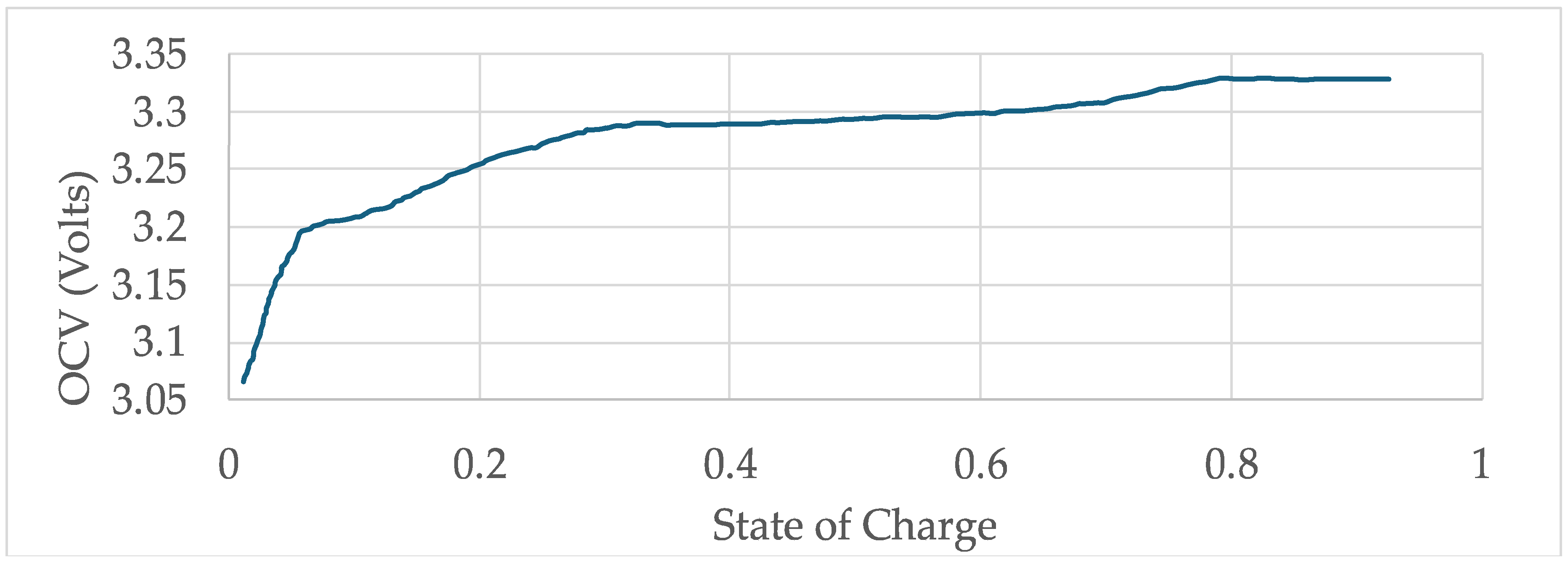
The SOC–OCV relationship obtained from the test bench is represented in
Figure 2.
For the purpose of cell characterization, a hybrid pulse power characterization (HPPC) test is performed to evaluate the battery response. The HPPC test provides critical data for battery management systems, aiding in the development of batteries.
The setup involves fully charging the battery, connecting it to a battery tester for precise current control and using a thermostatic chamber to stabilize the battery temperature if necessary. The test procedure involves applying short, high current discharge and charge pulses at various states of charge (SOC).
Typically, the test starts at 100% SOC and gradually decreases, e.g., by 10%, until a predefined lower limit is reached. During each pulse, the voltage and current data are recorded to calculate the internal resistance of the cell.
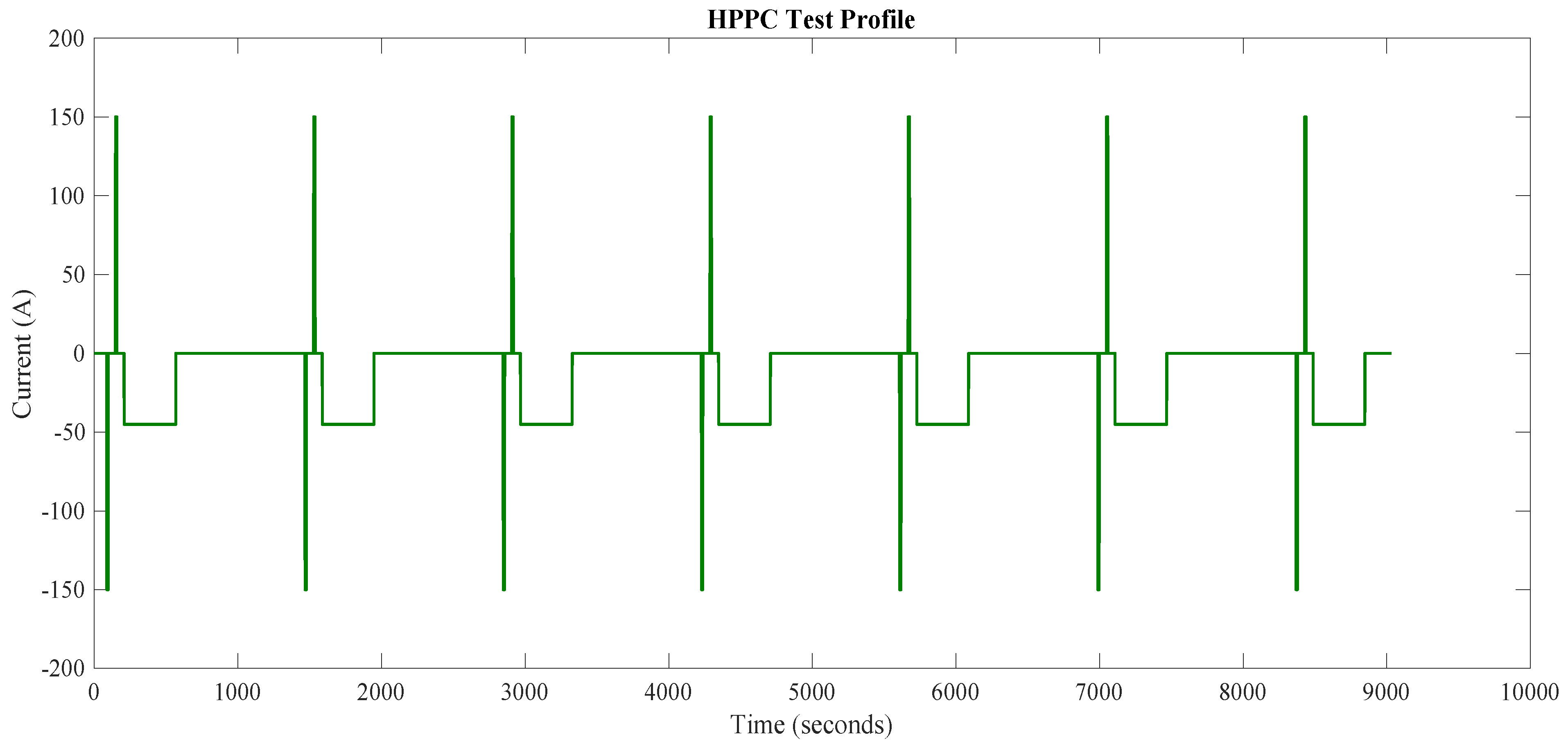
The current profile used in the HPPC test are visualized in
Figure 3, providing insight into the dynamic behavior of the cell.
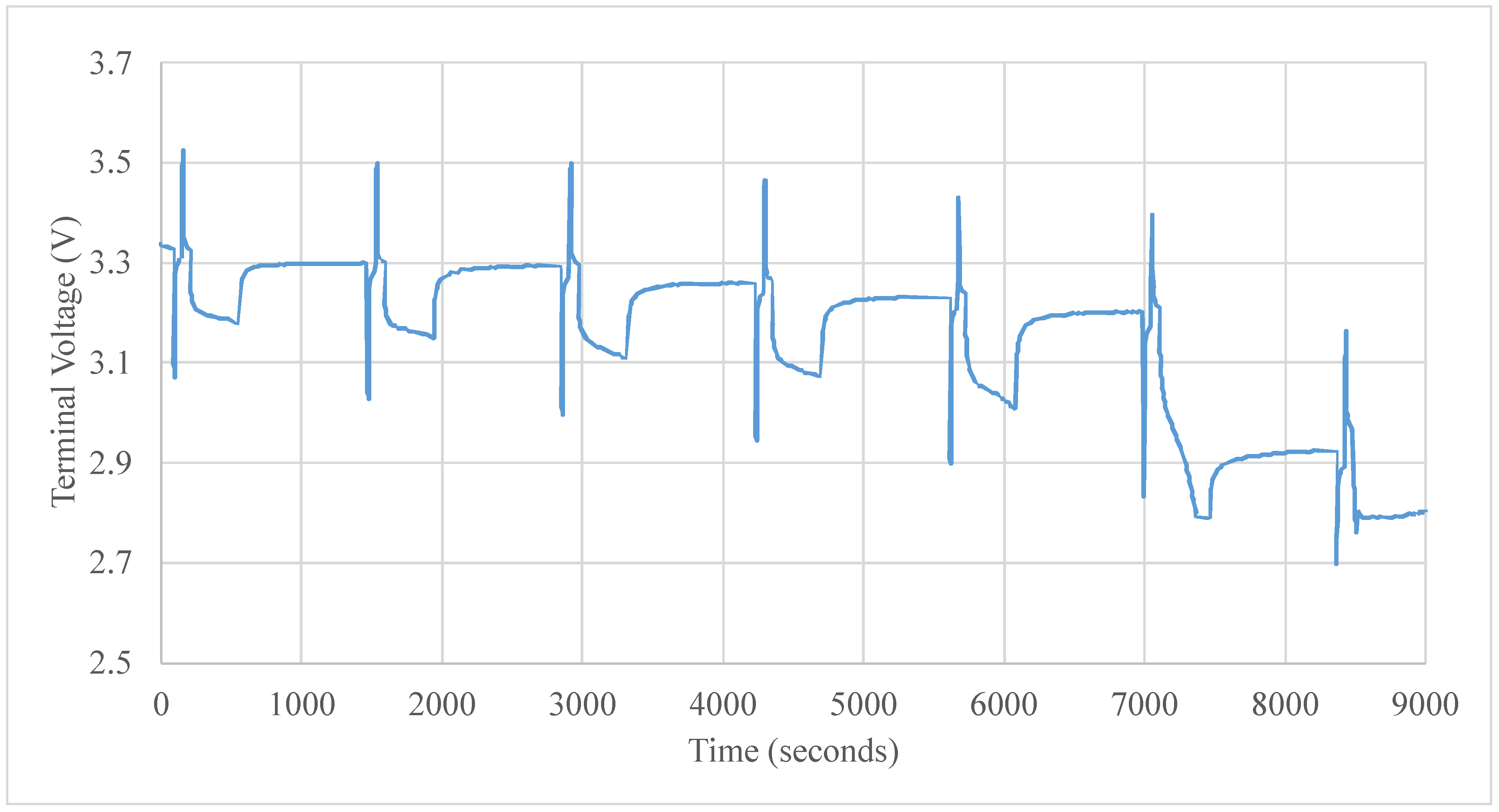
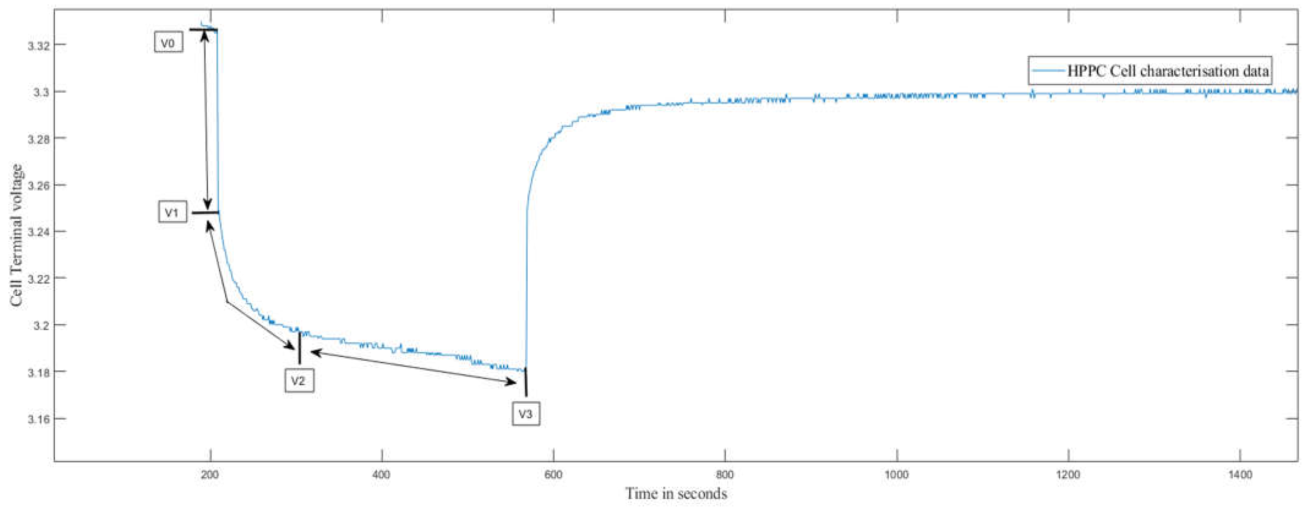
The terminal voltage of the test cell measured on the test bench during the HPPC test used for the estimation of cell parameters is visualized in
Figure 4.
2.2. Electrical Modeling of the Cell
To improve the accuracy of the battery state of charge (SOC) estimation, it is important to develop an equivalent circuit model (ECM) that not only provides high accuracy but also faithfully represents the dynamic characteristics of the battery.
A second-order Thevenin model with two RC networks is chosen for a comprehensive representation of the electrical behavior. These networks are crucial for simulating both short-term transients and long-term behavior.
The second-order Thevenin model is extended to include a variable voltage source to model the open circuit voltage of the cell, a series-connected variable resistor for ohmic resistance and two parallel RC branches with variable resistors and capacitors to model the polarization and charging and lowering transfer voltages as a robust foundation.
The obtained cell characterization data in
Figure 4 effectively represent the transient response and steady-state characteristics of a Li-ion battery, which are denoted by
Figure 5 illustrates the construction of the ECM, showing components such as variable capacitors, resistors and controlled voltage sources.
These elements combine to simulate important aspects, such as cell capacity and SOC dynamics; key to the accuracy of the model is the voltage-controlled voltage source, which non-linearly relates the SOC to open circuit voltage (OCV). The resistors R0, R1 and R2 each represent a different physical process in the cell.
R0 or series resistance: It represents the total ohmic resistance in the circuit, including the effects from the electrolyte, current collectors and contact resistance at the interfaces, which affect the cell’s initial response to an applied voltage or current. Higher R0 values can lead to increased energy losses during operation.
R1: It corresponds to the charge transfer resistance at the electrode interface during the charge and discharge process and significantly affects the kinetics of lithium-ion insertion and desorption. Lower R1 values indicate more favorable kinetics, leading to better battery performance, especially at higher temperatures and speed cycling.
R2: It refers to the resistance encountered by lithium-ions as they diffuse through the solid electrode material. This is especially important for mass transport at higher states of charge or faster cycling.
Analyzing these resistance components can provide researchers with insight into the electrochemical behavior of lithium-ion batteries and allow targeted refinements of materials and designs to improve performance.
In this paper, we consider all the ECMs to be a function of SOC; thus, the terminal voltage of the cell is represented as follows:
For the two R–C pairs, the voltage observed at the terminals is governed by
where V(t) is the terminal voltage over time; I(t) is the load current; R
ohmic is the ohmic resistance of the cell; and
are the capacitor voltages.
2.2.1. Identification of Cell Parameters
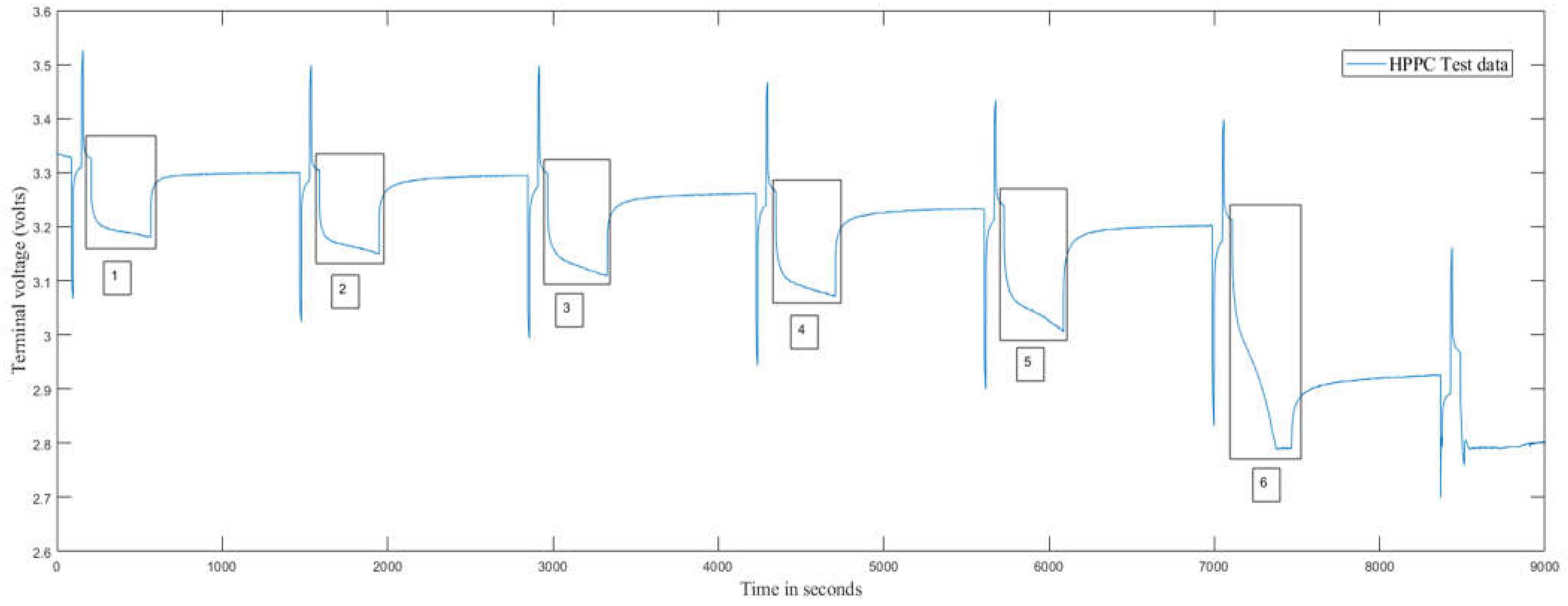
A regression algorithm referenced from [
20] was developed to identify the voltage drops at the current profile of 1C rate, and
Figure 6 represents the windows, which are referenced in the algorithm to develop the cell parameters from cell characterization data.
To identify the different parameters of the cell for modeling a 2RC Thevenin model, the data obtained from the cell characterization test are used. These data contain the battery profile in the form of pulses at each respective square load profile. The characterization consists of several key components:
Instantaneous voltage drop (V0 to V1): This drop is due to the ohmic resistance of the connectors, electrodes and electrolyte (R0).
First voltage drop (V1 to V2): This represents the mass transport effects within the cell.
Second voltage drop (V2 to V3): This reflects the double-layer effects during each discharge pulse.
The following voltage drops characterized on the discharge pulse at the respective SOC for estimating cell parameters are shown in the
Figure 7.
Parameters such as
serve as the regression parameters. Then, the parameters of the battery equivalent circuit model, which are
, can be defined as follows:
The obtained , , are used in the calculation of and from Equations (1) and (2).
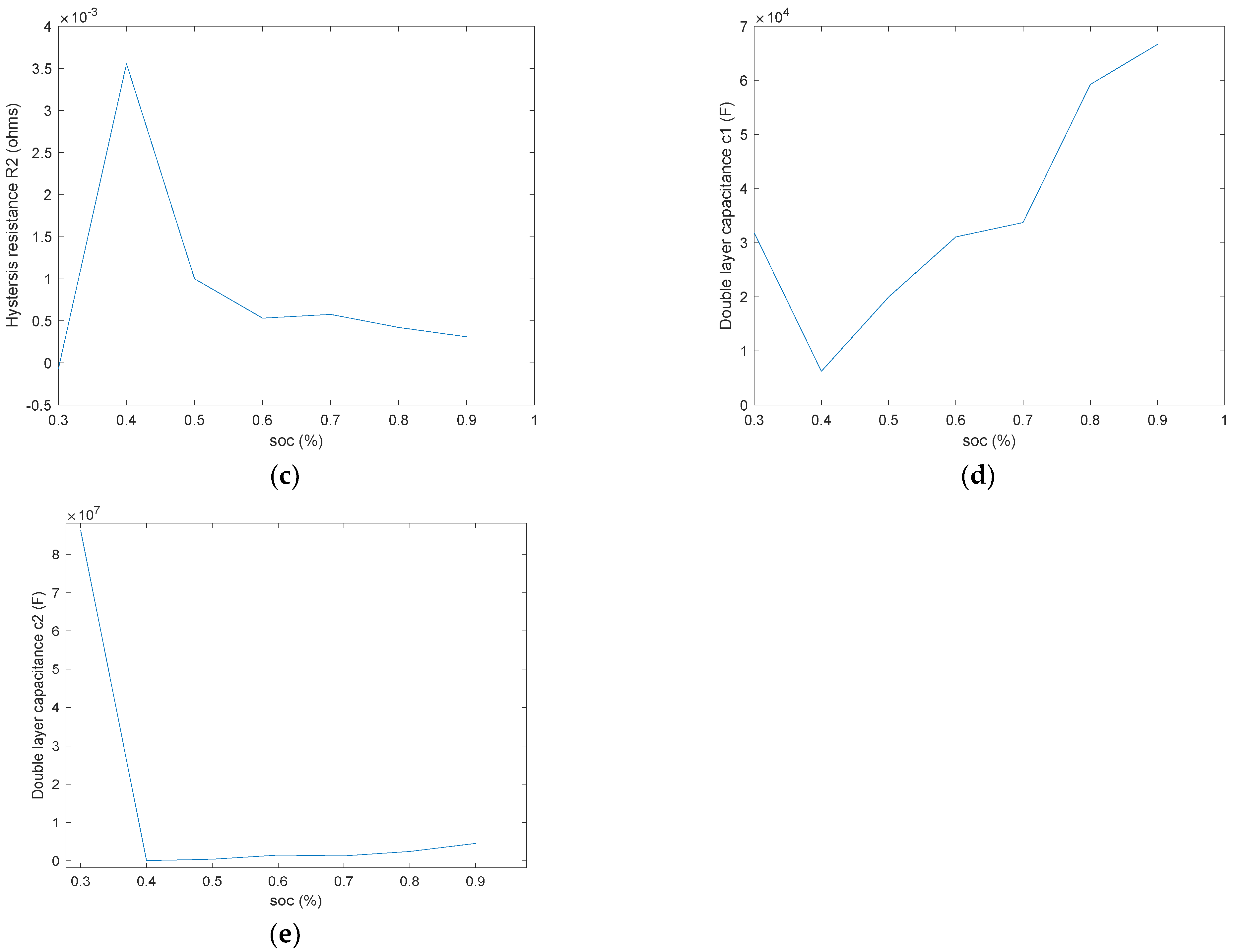
For all the different time segments of different SOC values at each HPPC current profile, through parameter identification, the equivalent circuit model parameters are obtained, and the obtained parameter values from HPPC test data are visualized in
Figure 8.
2.2.2. Validation of the Cell Model
The single-cell model was validated using Coulomb counting for the state of charge (SOC) estimation applied to a 2RC Thevenin circuit. The equivalent circuit model (ECM) parameters of the cell were modeled as a function of SOC and temperature. The current profile used for cell characterization was also used to validate the model by simulating it with voltage measurements taken from a test device.
The parameters of the simulated battery are listed in
Table 1.
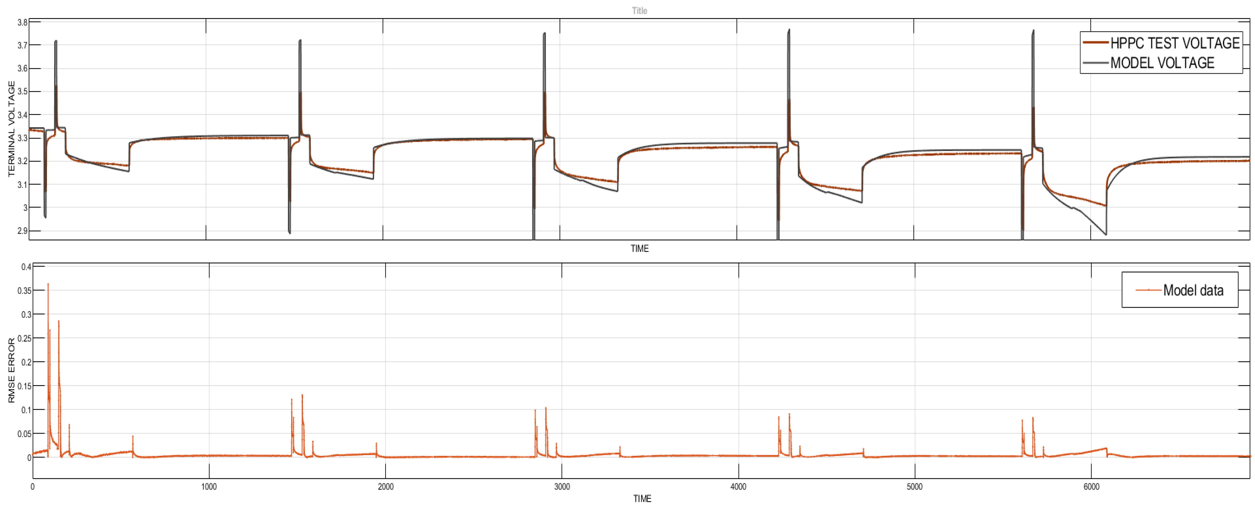
The validation results indicate the ECM modeled with estimated battery parameters in
Figure 9. However, there are deviations in accurate prediction of the cell voltage, with RMSE and MAE errors reaching up to 0.4% at certain instances. These deviations suggest that further refinement of parameter estimation using advanced numerical methods is necessary to improve the model’s accuracy for implementation in real-time applications.
3. Thermal Modeling
Battery thermal management and electrical operation are closely linked, as battery performance and safety are significantly affected by temperature. During charge and discharge cycles, batteries generate heat due to internal resistance and electrochemical reactions, which in turn affect the battery’s temperature.
These temperature variations affect the battery’s electrical performance, including capacity, efficiency and internal resistance. High temperatures can increase capacity loss, while low temperatures can reduce the available capacity and increase internal resistance. Furthermore, excessive heat can cause thermal runaway, a hazardous condition that can result in fires and explosions, highlighting the need for effective thermal management to prevent such incidents.
Maintaining the cells within a specific temperature range ensures maximum performance and lifespan. Heat generation in the cell occurs primarily through an irreversible process due to the internal resistance while the current is flowing, and it is defined as follows:
where Q
irreversible (Joules) is the rate of irreversible heat generation; I (Amperes) is the current flowing through the cell; R (Ohms) is the cell’s internal resistance; t (seconds) is the time during which the current flows.
The fundamental principle of heat transfer under steady-state conditions governing the thermal behavior of the cell is defined as follows:
where Q
conduction (Joules) is the rate of heat transfer through conduction; Q
convection (Joules) is the rate of heat transfer through convection; Q
radiation (Joules) is the rate of heat transfer through radiation.
As our approach is a lump-based model, the Q
conduction is neglected, and the temperature range remains at a low temperature range; thus, Q
radiation is neglected. Only convective heat transfer (Q
convection) is considered in this paper.
where h (W/m
2K) is the convective heat transfer coefficient; A (m
2) is the surface area of the cell; T
cell (K) is the cell temperature; and T
ambient (K) is the ambient temperature.
6. Design of BTMS
In terms of battery thermal management, keeping batteries within acceptable temperature ranges is critical for their performance, durability and general safety. One extensively used approach is air cooling, which uses fans to remove the heat generated during battery operation. This introduction will explain the notion of air-cooling systems that use two fans over a battery pack with 12 cells. Furthermore, it will investigate the integration of an automated control system to govern the operation of these fans, guaranteeing effective cooling while minimizing energy usage [
23,
24].
6.1. Fan Control Algorithm
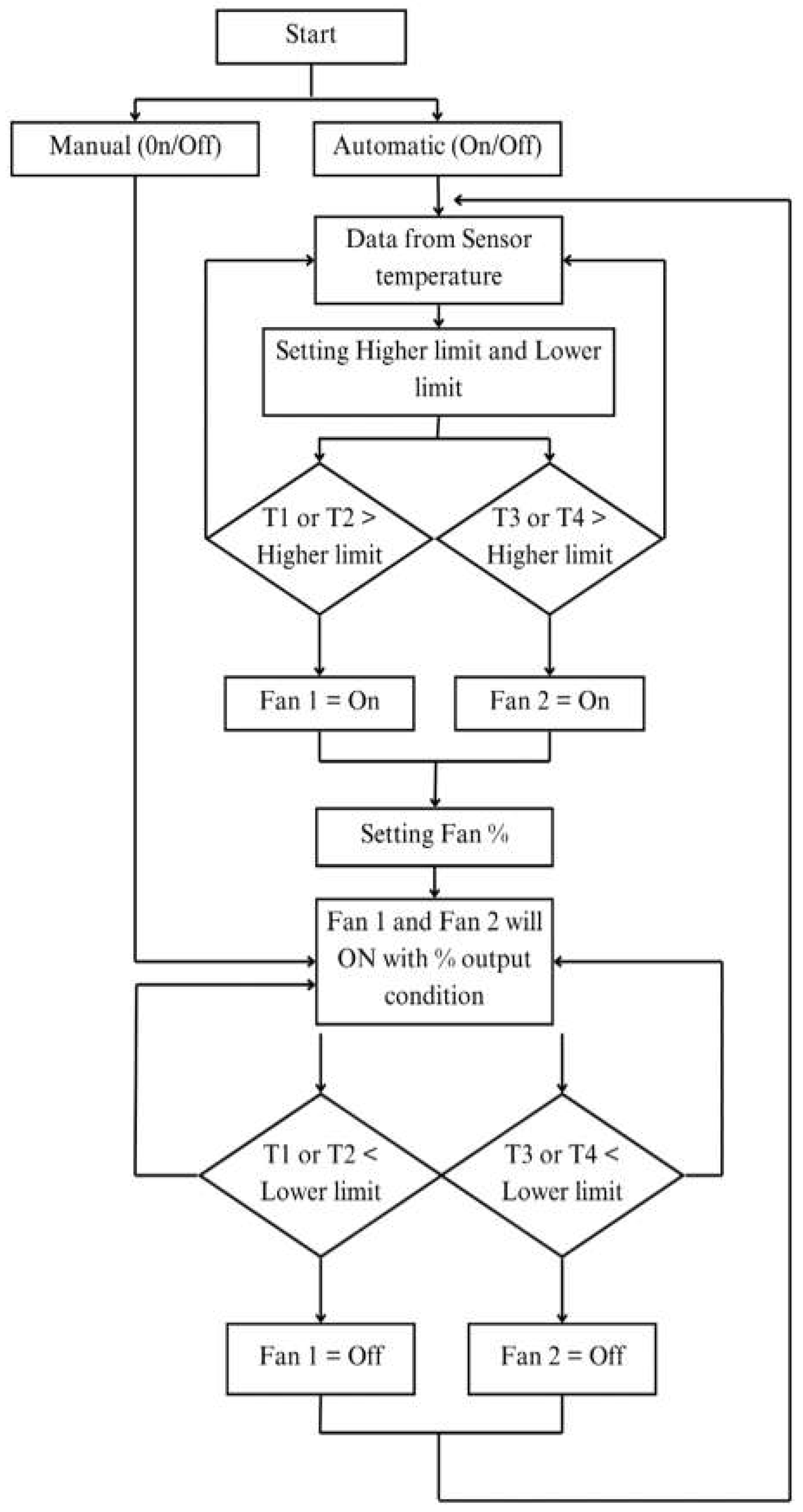
The fan control algorithm for battery cooling was created using Simulink State flow and Design flow chart is visualized in below
Figure 12. This graphical environment provides a visual depiction of the control logic, making it easier to comprehend and alter. The design method entailed designing four states: Manual On, Manual Off, Auto On and Auto Off. The transitions between the states were created using human input and temperature sensor data from important spots throughout the battery pack. The Auto On mode operates the cooling fan when temperatures surpass a predetermined higher limit, while the Auto Off state deactivates the fan when temperatures fall below a lower limit.
User input allows the user to override the automated control and manually switch the fan on or off. State flow actions were used to regulate the “fan control signal” transmitted to the actual cooling fan, allowing for variable fan speed control via duty cycle modifications. This design enables optimal thermal management of the battery by automatically controlling the cooling fan based on temperature conditions while still allowing for user intervention when needed.
6.2. Integration of BTMS with EKF for Online Estimation of Battery Parameters
The model-based design, originally presented in [
14], provides a framework for estimating the state of charge (SOC) in a battery management system (BMS).
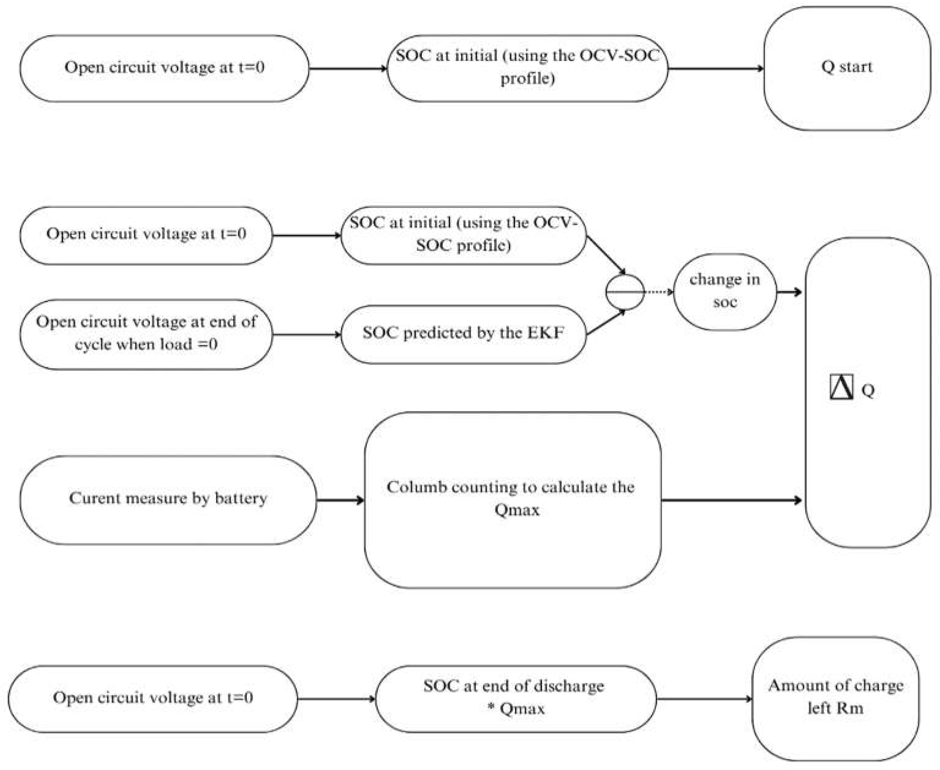
In our approach, the measured current (Icell) is integrated with an extended Kalman filter (EKF) to achieve real-time estimation of the state of charge (SOC). The EKF-based SOC estimation is coupled with a cell equivalent circuit model (ECM) that is carefully developed using detailed cell characteristic data.
The EKF works by estimating the voltage drop between the RC circuit and the SOC using a state-space representation matrix. SOC is fed back to the ECM closed circuit to predict the cell terminal voltage. In this closed-circuit system, the measured voltage serves as the reference input. The difference between the actual and predicted voltages is calculated and used in the update step of the EKF to predict the state for the next time interval.
In our model-based BMS design, the EKF effectively addresses the limitations of traditional Coulomb counting methods by accounting for observation noise and non-linearities. It also leverages a discrete non-linear state-space model of the cell and iteratively minimizes the variance in the SOC estimate using a recursive algorithm.
This robust methodology ensures accurate and reliable SOC estimation, which is critical for an efficient battery management strategy. To validate the performance of the EKF-based model, a comparison is performed with the SOC estimates obtained using the Coulomb counting method, which demonstrates good robustness and accuracy in real applications.
The layout shows the overview of a battery management system (BMS) designed using air-cooled Li-ion battery pack in a 6S-1P configuration with online parameter estimation. The system starts with an external power demand input that the BMS needs to manage to ensure the safe operation of the battery pack.
The BMS handles tasks such as power monitoring, cell balancing and fan speed control while estimating the state of charge (SOC) using Coulomb counting. The battery pack receives a controlled current input from the BMS to ensure uniform charging and discharging of all cells.
The estimated SOC is compared with the actual SOC to determine the error, which is then processed by an extended Kalman filter (EKF). This EKF consists of a propagation step and a correction step to refine the SOC estimate and provide revised system state outputs. The designed model of BMS enables accurate real-time monitoring and management of the battery pack to ensure optimal performance and lifespan.
7. Simulation and Analysis
To investigate the effectiveness of the proposed method, a simulation model of the entire BMS was created in MATLAB/Simulink (2024 A), as described in the BMS layout in below
Figure 13. The analysis begins with an examination of the cell terminal voltages and compares the real-time test data with the voltages simulated using the 2RC equivalent circuit model (ECM).
7.1. Voltage Predicted by the Model for HPPC Test
The performance of the cell voltage model was evaluated by comparing the predicted terminal voltage with the measured real-time voltage data during cell discharge.
Despite a higher initial error, the EKF algorithm effectively fine-tunes the battery parameters over time. As illustrated in
Figure 14, the estimation error decreases progressively. Compared to the Ah method, which exhibits an error of 0.4%, the EKF achieves a significantly lower average estimation error of less than 0.1%. This demonstrates the superior accuracy and reliability of the EKF approach in estimating battery parameters.
7.2. Model Validation Using Real-Time Current Profile
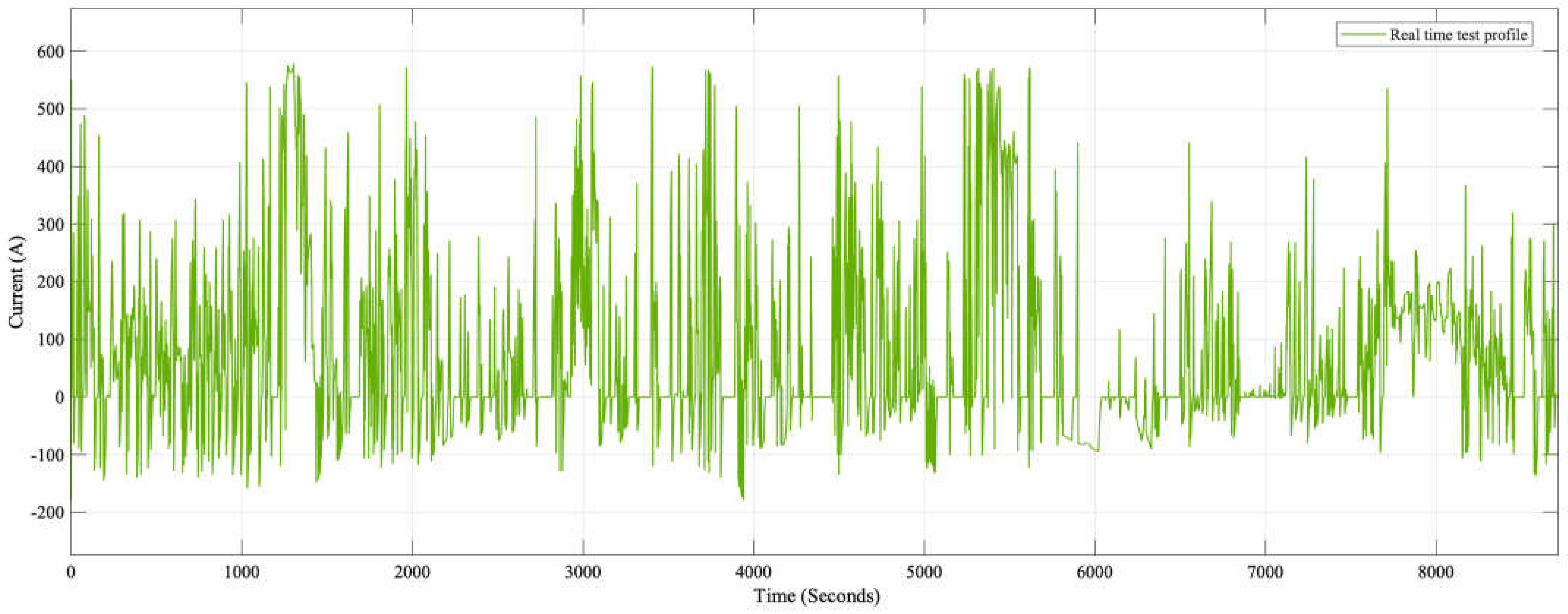
The load profile was obtained from the electric vehicle tests carried out as part of the InnoTherms project and is visualized in
Figure 15.
The current measured at the battery was collected from the test vehicle operating under real-time conditions. These data are utilized to validate the battery management system (BMS) model and to predict battery parameters accurately.
The performance of the cell voltage model was evaluated by comparing the predicted terminal voltage with the voltage data measured in real time during the cell discharge, as visualized in
Figure 16.
After experimentation with different sample times, fixed step sizes and model tolerances, the following results were obtained with a fixed step size and sample time of 0.15 and a model tolerance of 0.001. These settings showed that the model allows for accurate prediction of the battery parameters.
The close agreement between these two data sets over most of the experimental time frame indicates that the 2RC-ECM effectively captures the dynamic behavior of the cell’s voltage response over the entire cycle. Although the root-mean-square error (RMSE) analysis highlights some discrepancies, the errors are still confined to a narrow range, indicating that the model is robust under dynamic loading conditions and effectively filters out noise.
Moreover, the minimal deviations observed in the error plots highlight the model’s robustness in dealing with dynamic loading conditions and noise.
7.2.1. State of Charge Results
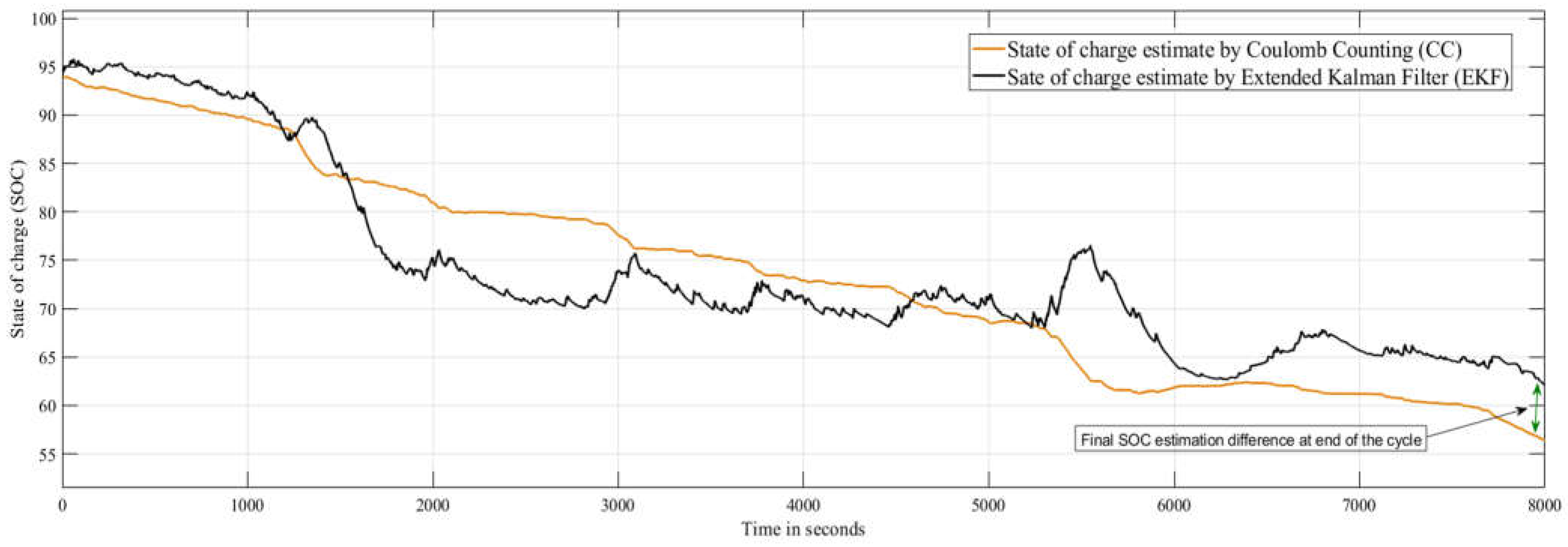
SOC predictions using the Coulomb counting (CC) method and the extended Kalman filter (EKF) algorithm are visualized in
Figure 17.
Initially, the CC and EKF methods are close to each other. As the experiment progresses, the EKF’s ability to incorporate new measurements and adjust its estimates accordingly becomes apparent, allowing for more accurate SOC tracking. This adaptability is critical to managing the cumulative errors and inherent noise associated with real-time battery operation; the CC method has limitations in these areas. The deviation between the estimates of the two methods becomes larger, especially under high discharge and varying load conditions, highlighting the superior performance of the EKF in maintaining accuracy over time.
7.2.2. Visualization and Analysis of Temperature Prediction
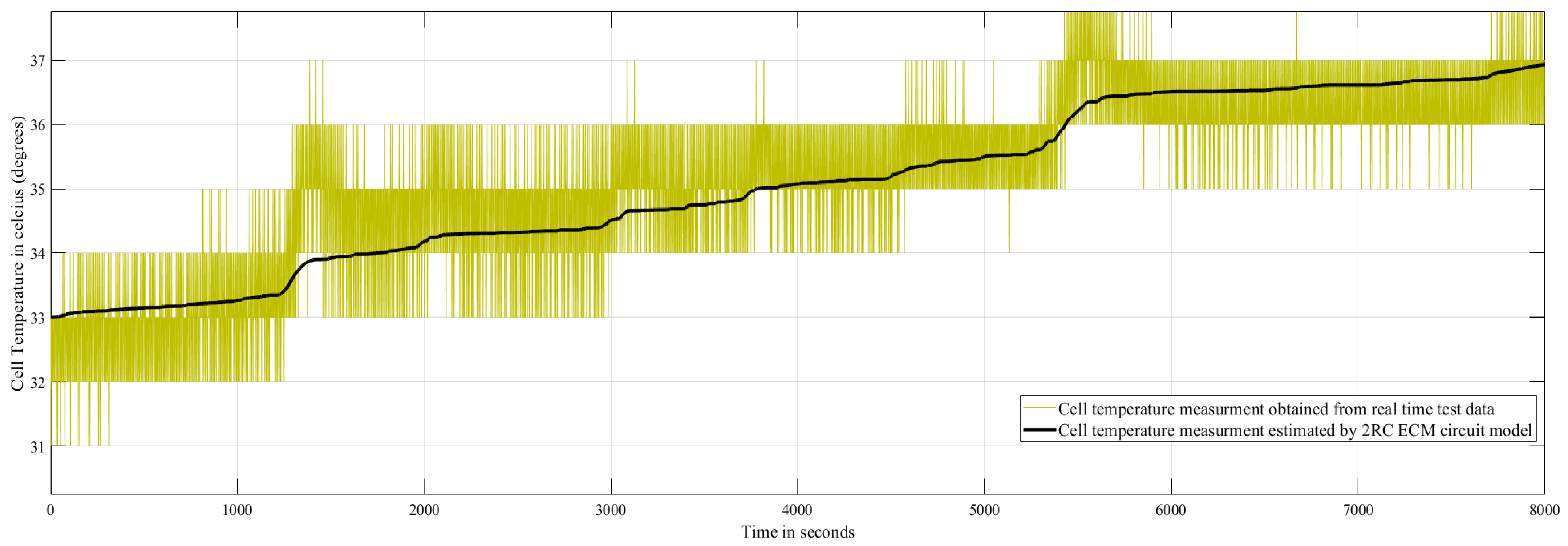
The analysis typically involves plotting two key sets of data; the actual temperature measurements and the temperature predicted by the model is visualized in below
Figure 18.
The optimal results in
Figure 18 show high agreement between the real-time temperature data and the model predictions throughout the cycle. Such a close agreement means that the temperature model is robust and accurate, effectively capturing the thermal behaviors of the cell.
This validation not only improves the safety and efficiency of battery operations but also contributes to the broader goal of advancing battery technology for a variety of applications. Also, implementing an extended Kalman filter (EKF) for a state of charge (SOC) prediction by a battery management system (BMS) poses a number of complex challenges that require meticulous attention to ensure optimal performance.
8. Conclusions
A major advancement in the field of battery technology is made by integrating the equivalent circuit model (ECM) and an extended Kalman filter (EKF) into battery management systems (BMSs). This model-based approach not only captures the dynamic behaviors of the battery more accurately but also improves the accuracy of SOC prediction by effectively removing real-time data fluctuations. The implementation of the extended Kalman filter (EKF) state of charge (SOC) estimation algorithm involves several critical steps to ensure accurate and efficient performance.
First, proper battery model selection and parameterization are essential. The 2RC equivalent circuit model (ECM) selected accurately represents the cell dynamics while maintaining computational performance. Second, it is important to correctly set the initial conditions and fine-tune the filter parameters. Process and measurement noise covariance is critical for the convergence and stability of the EKF. Third, the evaluation of model tolerances and solver settings (both fixed and variable) proved that fixed step settings and carefully selected tolerances are optimal, ensuring reliable performance without compromising accuracy.
Finally, it is important to consider the sampling time, as differences in intervals affect the accuracy of the SOC estimation. Taken together, these steps highlight the complexity of EKF implementation and the actions required to address it successfully.
The robust framework provided by this integration improves the performance and accuracy in battery parameter estimation, making the model especially suitable for online estimation in real-time applications, such as electric vehicles and other energy storage systems. With minimal computational complexity and a reduced need for large-scale training data, the EKF is proved to outperform traditional and other model-based approaches, positioning it as a highly viable solution to modern battery management challenges.

