Abstract
Because current collectors (CCs), Binders (BDs), and conductive additives (CAs) in cathodes and anodes do not directly contribute to charging and discharging, they decrease the energy density of the battery. Improvement of battery energy density is essential for future batteries. If it were possible to pack electrode active materials into the empty space without using CCs, BDs, and CAs, the energy density of the battery would increase. Therefore, attempts to avoid using these materials in batteries are being investigated. In this review article, methods for manufacturing electrodes without using these materials, as well as the performance and durability of the electrodes, are summarized and discussed. After explaining the function and necessity of the CCs, BDs, and CAs, methods for manufacturing electrodes without using CCs, BDs, and CAs, as well as the performance and durability of the electrodes, were summarized and discussed. In addition to battery performance, the mechanical durability of the electrodes is also explained since not using CCs, BDs, and CAs will cause problems with the electrodes’ mechanical durability.
1. Introduction
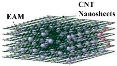
Lithium-ion batteries (LIBs) greatly overcome the drawbacks of conventional secondary batteries, opening up a wide range of uses for secondary batteries [1]. Consequently, the use of LIBs has greatly changed our lifestyle. Recently, the performance of batteries used in electric vehicles and batteries for storing fluctuating renewable energy has become a matter of great concern [2,3,4]. New LIBs with improved performance based on present LIBs [5] and post-LIBs [6] that have evolved from LIBs have improved energy density, input/output performance, safety, etc. This further improvement will allow secondary batteries to enter new fields more than ever before. This improvement is, for example, the development of solid electrolytes for all-solid-state batteries [7] and cathode and anode materials that exhibit high capacity and are considered an incidental technology for making full use of these materials [8]. In addition to these major improvements, various small improvements will also be necessary to bring these major improvements into practical use [9,10,11,12]. Small improvements include improving the energy density by reducing the amounts of inactive-material such as current collectors (CCs) [13], binders (BDs) [14], and conductive additives (CAs) [15], which cannot store charges in electrode active material (EAM) layers in anodes and cathodes (Figure 1). By not adding inactive materials such as CCs, BDs, and CAs that do not directly contribute to energy storage, more EAM can be placed in the battery, therefore achieving an improvement in energy density. For example, a composite electrode, through the deposition of EAM directly onto a separator to avoid the use of a metallic CC, delivers specific capacities corresponding to more than 6 times the gravimetric capacity of an electrode coated on Al foil [16]. A freestanding graphene-encapsulated silicon (Si) nanoparticle aerogel anode exhibited superior electrochemical performance, 4 times the gravimetric capacity of a traditional Si electrode on Cu foil fabricated by a typical slurry method [17]. Freestanding, binder-free, and conductive additive-free mesoporous titanium dioxide/carbon hybrid electrodes were prepared from co-assembly of a poly(isoprene)-block-poly(styrene)-block-poly(ethylene oxide) block copolymer and a titanium alkoxide exhibited high areal capacity which represented a 9-fold increase compared to conventionally cast electrodes [18]. Various attempts have been made to increase the energy density.
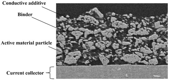
Figure 1.
Cross-sectional scanning electron microscopy (SEM) image of the cathode.
In this review paper, after describing the functions and necessity of CCs, BDs, and CAs in LIBs, we will present examples where these CCs, BDs, and CAs can be eliminated from the battery by replacing their required properties with alternative chemistries and specific structures, and discuss a comparison of the performance of these electrodes. In addition to the battery characteristics of cycle stability and rate characteristics, the mechanical strength of the electrode, versatility of the manufacturing method, and low cost of materials are also considered from the perspective of whether electrodes manufactured based on these ideas can be used in actual batteries. Ideal electrodes would not contain any of the CCs, BDs, and CAs, but in order to maintain the strength and electronic conductivity of the electrode, one or two of the CCs, BDs, and CAs are excluded from the electrode, and the remaining among the CCs, BDs, and CAs have a chemical structure that substitutes for the functions of the ones that were excluded. These classifications will also be discussed in detail. The biggest problem with removing CCs, BDs, and CAs from electrodes is the mechanical strength of the electrodes. Focusing on this point, this paper summarizes the research to date. As the electrode, the paper focuses on the Si anode, which swells and shrinks during charging and discharging. It is very difficult to solve this problem even with the Si anode using CCs, BDs, and CAs. The ideas that are trying to solve this problem, especially the latest papers, will be summarized.
2. The Role of Current Collectors, Binders, and Conductive Additives in Present Batteries
2.1. Current Collector
As its name suggests, CCs work effectively as electron conductors that collect or distribute electrons from/to the EAM layers. The CCs also contribute to holding the EAM layers on the surface of CCs. The CCs usually have a foil shape, and the EAMs are formed on the foil. Aluminum (Al) is used for the cathode CC [19], and copper (Cu) is used for the anode CC [20]. Because the cathodes are exposed to high voltage, Al, which has high corrosion resistance, is used as a CC for cathodes. The anode uses Cu, which does not cause an alloying reaction with lithium (Li). The thickness of the CC is 4–8 μm. The weight ratio of the CC in the battery is 3–6% [20,21]. Because the thickness and weight of the CCs cause a decrease in the energy density of the batteries, there is a desire to make the CCs as light and thin as possible. However, if the CCs are too thin, the characteristics that the CCs should have, such as holding the EAM, are considerably degraded. In particular, when the volume of EAM particles changes considerably with charging and discharging, such as for Si anode materials, the mechanical strength of CCs is required [22]. In addition, CCs must be corrosion-resistant. In particular, since cathodes are placed at a high potential during the charging process, oxidation of the metal on the metal CCs causes elution of metal ions or precipitation of metal oxides on the surface of the metal CCs [23]. Because of surface oxidation, problems such as shedding of the EAMs from the CCs and increased electronic resistance between the EAM and the CCs occur. To improve corrosion resistance, two methods are being considered: using an expensive metal with high corrosion resistance as the CC material or using a carbon material. From a practical point of view, an option would be to use carbon materials, which would allow price and energy density to be met to some extent [24,25]. The CCs not only function for the EAM but also contribute to the retention of performance and the safety of the battery by holding the active material layer in place [13]. Recently, the CCs have also come to play a major role in the safety of the battery by functionalizing it. There is a study on mitigating advanced thermal-runaway techniques by modifying CCs. Wang and Qiao proposed CCs that are constructed as a continuous piece [26]. When LIBs are mechanically impacted during thermal runaway, The CCs fracture into discontinuous pieces. The site where internal shorting occurs in LIBs is completely isolated from the other pieces in an electrode. Hence, the internal impedance can be significantly increased by separating the pieces, leading to a decreased heat generation rate and mitigation of thermal runaway.
2.2. Binder
The BD functions to hold the cathode and anode EAM particles as an EAM layer on the CCs. BDs have certain requirements, such as chemical and electrochemical stability during battery operation and storage, as well as the ability to hold EAMs [27]. In the EAM layer, the BD exists in a mixed state with the EAM and the CA. The mixing ratio is several percent by mass. Considering the environment in which the cathode and anode electrodes are exposed, and the manufacturing conditions, commercially available batteries use polyvinylidene difluoride (PVDF) BD [28] for cathodes and styrene–butadiene rubber (SBR) BD [29] for anodes. Other results include research into the size of EAM particles and CAs that maximize electrode performance, such as cycle characteristics and rate characteristics, using PVDF, as well as indicators for optimizing the ratio of BDs with EAM and CAs [30]. Various efforts have been made to improve the binding ability of binders, such as modifying the molecular structure and introducing functional groups [31,32]. Furthermore, various studies are being conducted on binders for post-lithium-ion batteries [33]. From an eco-friendly perspective, attempts have already been made to use binders made from bio-based materials [34].
Recently, BDs have been proposed to retain EAM particles even when the volume of the EAMs increases or decreases considerably during charging and discharging processes, as observed for high-performance Si anodes [35]. Moreover, water-based BDs have recently been actively developed to avoid using organic solvents in the production of electrodes to make the manufacturing process more environmentally friendly [36]. Although its content in the EAM layer is low, reducing the BD can improve the energy density of the battery. Many studies are being conducted on reducing the amount of BD by improving the performance of the BD [30].
2.3. Conductive Additives
The EAM of LIBs has relatively low electronic conductivity. However, because of the demand for using large currents during the charging and discharging processes, CAs are added to the EAM layer to assist the electronic conductivity of the layers. Carbon materials are mainly used, and various materials, such as acetylene black [37], graphene [38], carbon nanotubes [39], and carbon nanofibers [40], are also used. The amount added to the EAM layer is several percent by weight. In many cases, the BD mentioned above, and CAs together account for approximately 10% of the total weight. The CA contributes to creating an electron conduction path in the EAM layer. The type of CA to be used and the amount of CA to be added are crucial in creating an electron-conductive path. Therefore, many reports are available on the efficient study of electronic conductivity paths by adding CAs [10,30]. Some papers state that high electronic conductivity does not necessarily lead to high capacity at high C rates due to the complex interrelationship between the electronically conductive carbon main created by the conductive additive and ion diffusion within the EAM layers [41] and the optimization of conductive paths within the EAM layers is discussed from both experimental and analytical perspectives [42,43].
3. Current Collector-Free Electrodes
The term “CC-free” has two meanings. If the CC refers to a metal CC, then changing the metal CC to a nonmetal foil, for example, will result in CC-free electrodes. If the CCs are eliminated and the EAM layer is freestanding and can be molded by adding an auxiliary agent, the result will be CC-free electrodes. The CC-free electrodes will be explained by dividing them into two categories. Of all the inactive materials in a battery, the CCs take up the most mass and volume, so reducing the CCs as much as possible would greatly contribute to improving the battery’s energy density.
3.1. Metal-Free Current Collector
Since metal CCs are heavy and have a risk of corrosion (Figure 2) [23], it is desirable to use carbon-based foils as CCs. Carbon CC foils are composed of carbon nanotubes (CNTs) [44], carbon fibers (CFs) [45], reduced graphene oxides (RGOs) [46], graphene oxides (GOs) [47], and carbon-based polymers [48]. In these examples, carbon-based CC foils are produced, and EAM layers are formed on the carbon-based foils. Currently, various problems, such as poor performance and durability, are emerging and being resolved depending on which carbon-based material is used. Although CNTs have excellent electronic conductivity, they have poor moldability, and the toughness of the molded CC with CNTs remains problematic.
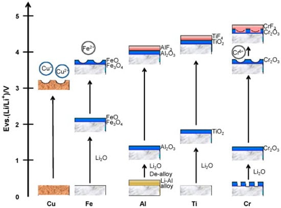
Figure 2.
Schematics of passivation for several metals in a nonaqueous alkyl carbonate solution containing LiPF6 salt. Reproduced with permission from [23] Copyright © 2018, Elsevier B.V.
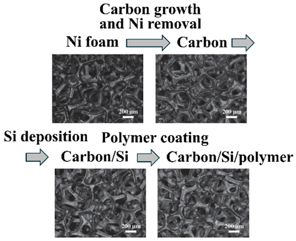
Although CFs have no problems with electronic conductivity, toughness, or electrochemical stability when used as CCs, it has been reported that CCs containing CFs as a main component have problems with adhesion to the EAM layer. One way to solve this problem is to coat the CF surface with other organic substances [49]. Sharma et al. prepared a polymer (P)-based CF/CNT composite (CF-CNT-P) as a CC for battery cathodes by depositing a thin layer of CNTs and polymer slurry on aligned carbon fibers, in which P was a poly(L-lactide-co-ε-caprolactone; polylactic acid [PLA]:polycaprolactone [PCL] = 70:30 mol%) polymer. The CC foil (1.81 mg cm−2 and 15 µm thick) produced by this method is much lighter than conventional Al foil (4.35 mg cm−2 and 15 µm thick) [50]. Similarly, it is extremely difficult to assemble CCs from particulate RGOs and GOs, which have excellent electronic conductivity and electrochemical durability. Instead of assembly methods for RGOs and GOs, chemical vapor deposition (CVD) methods are considered for creating these continuums. To convert the CC structure into a three-dimensional structure, it has been proposed to use a template to create a structure of RGOs or GOs using CVD and then remove this template to create a three-dimensional CC foil (Figure 3) [51].
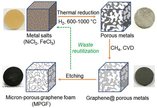
Figure 3.
Schematic of the synthesis of micron-sized porous graphene foam from a metallic salt precursor. The overall process contains three steps: thermal reduction of metallic salts, CVD growth of graphene in a porous metal template, and removal of the metal template. The photos show a nickel chloride chip, a micron-porous nickel (Ni) chip, a graphene-coated micron-porous Ni chip, and a micron-porous graphene foam chip 13 mm in diameter made in each step. Reproduced with permission from [51] Copyright © 2019, Elsevier B.V.
3.2. Current Collector-Free Electrodes (Freestanding Electrodes)
Electrodes are frequently formed by mixing carbon materials with EAM particles to form an electrode shape. In this case, since carbon materials with high electronic conductivity are mixed in the EAMs, these carbon materials are considered CAs, but here, no CCs are in the anodes and cathodes, and the carbon material acts as CCs. Therefore, highly conductive carbon materials are considered CCs.
Phiri et al. reported that freestanding electrodes can be fabricated using a simple method. Using dimethylformamide as a dispersion solvent, slurries containing lithium manganese oxide (LiMn2O4), poly(vinylidene fluoride-co-hexafluoropropylene) (PVdF-HFP), vapor-grown carbon fiber (VGCF), 1-butyl-1-methylpyrrolidinium bis-(trifluoromethanesulfonyl)imide (Pyr14-TFSI), and lithium bis(trifluoromethanesulfonyl)imide (LiTFSI) were prepared as plasticizers. After applying the slurry to a glass substrate and drying it, an EAM layer was formed on the glass substrate. Peeling off the formed EAM layer created a freestanding electrode. The thickness of this electrode was more than 200 μm, and bending or folding the electrode did not affect the shape of the EAM layer. Stable charge/discharge cycles were possible for 5000 cycles (Figure 4) [52].
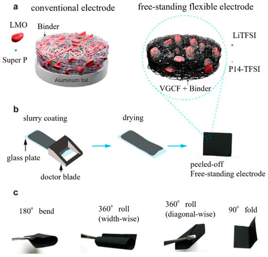
Figure 4.
(a) Schematic of the conventional electrode and the freestanding flexible electrode; (b) schematic of the conventional electrode preparation process; and (c) digital images demonstrating freestanding electrode flexibility. Reproduced with permission from [52] Copyright © 2020, American Chemical Society.
The electrospinning method is also frequently used to fabricate freestanding carbon films. In the electrospinning method, a carbon-based film is formed, and then the fibers of the carbon material forming the film themselves become the EAM [53], a method in which the EAM is deposited on the surface [54]. In another frequently used method, a precursor of an EAM or an EAM is mixed into the carbon material to be spun before performing the electrospinning method, and the EAM is fixed on the surface or inside the carbon fiber material produced by spinning [55,56]. As shown in Figure 5, ferric acetylacetonate, phenylphosphonic acid, and polyacrylonitrile were dissolved in N,N-dimethylformamide to form a homogeneous solution. This solution was electrospun on an Al foil. After electrospinning, the mat on the Al foil was peeled off. The mats were then carbonized in a tube furnace with an H2/Ar flow at 800 °C. The final product of Fe2P was contained in carbon fibers [57].
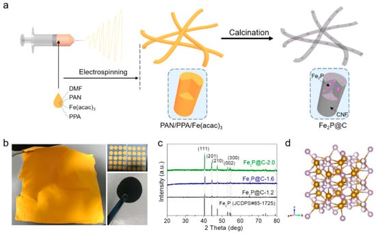
Figure 5.
(a) Schematic of the synthesis process used to produce the Fe2P/C composite nanofibers. (b) Photos of an obtained mat and the cut discs (yellow) before and (black) after calcination. (c) XRD patterns of different samples. (d) Crystal structure of Fe2P. Reproduced with permission from [57] Copyright © 2021, American Chemical Society.
One method has also been devised in which EAM particles and carbon material as the source of CCs are dispersed in a solvent and then filtered to form a membrane. This method is the simplest way to make freestanding electrodes [46,58]. To maintain the durability of electrodes, heat treatment or chemical treatment is used to harden the membrane after it is formed [59,60].
To fabricate simple cathodes using Ni redox, a dispersion solution of MWCNTs/CNFs was first filtered to form a base layer of multiwalled carbon nanotubes (MWCNTs) and cellulose nanofibers (CNFs) on filter paper. Next, a second dispersion solvent in which Ni, NaCl, MWCNTs, CNFs, and additives were dispersed was prepared, and the second dispersion solvent was filtered through filter paper. Finally, heat treatment was performed under an H2/Ar atmosphere to carbonize the cellulose nanofibers to CFs in the layer created by filtration. Consequently, cathodes in which Ni was supported in three-dimensional carbon high electron conductivity CCs were fabricated (Figure 6) [61].
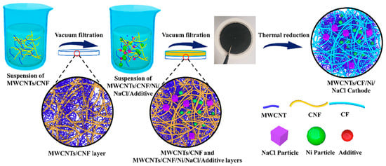
Figure 6.
Schematic of the fabrication routes for preparing multiwalled carbon nanotube (MWCNT)/carbon fiber (CF)/Ni/NaCl cathodes. CNF: cellulose nanofiber. Reproduced with permission from [61] Copyright © 2020, Elsevier B.V.
4. Binder-Free Electrodes
To eliminate the need for BDs when creating electrodes, the addition of adhesiveness between the CC and the EAM and bondability between the EAM particles are required with other factors, such as intermolecular interactions. As a first attempt, EAMs were synthesized directly from the surface of CCs. Various methods for synthesizing EAMs have been attempted. Direct synthesis of EAMs has rarely been considered for cathode and anode materials such as lithium transition metal oxides and graphite, which have been put into practical use. In general, direct synthesis of EAMs is being attempted for new cathode and anode materials. Other methods have been proposed, such as confining EAM particles within a matrix of conductive material. Some representative examples of characteristic methods will be explained.
4.1. Direct Growth of Active Materials on Current Collectors
Yu et al. proposed the preparation of carbon-coated FeS (theoretical capacity of 609 mAhg−1) on carbon cloth films, as shown in Figure 7 [62]. The anode is completed by applying a solution containing a dispersed FS precursor and conductive carbon precursor onto carbon cloth and firing it. The anode EAM particles are deposited on the carbon cloth and are buried in the conductive carbon layer formed by firing. The conductive carbon layer holds the EAM particles within the electrode without BD (Figure 7b). The conductive carbon layer surrounding the FeS particles can accommodate the volume change in the FeS particles during the charging/discharging processes, resulting in improvements in the cyclability and rate capability of the FeS anode.
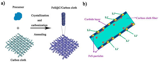
Figure 7.
(a) Schematic of the fabrication steps for the FeS@C/carbon cloth. (b) Schematic of the FeS@C/carbon cloth composites with bicontinuous electron/ion transport pathways. Reproduced with permission from [62] Copyright © 2015, American Chemical Society.
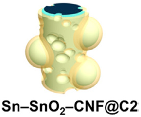
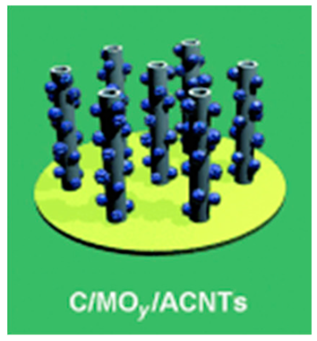
A method in which cylindrical tin (Sn) oxide or vanadium (V) oxide is formed on carbon cloth using Ni and cobalt oxides as templates has been proposed. The cylindrical oxide is laminated with a nitrogen- or oxygen-doped carbon layer (Figure 8) [63]. The laminated carbon layer in the carbon layer/active oxide layer/carbon layer/active oxide layer in anodes acts as an intermediate layer to prevent the electrolyte solution from coming into contact with the Sn oxide or V active oxide surface. This layer inhibits the formation of the SEI layer. It also contributes to alleviating volume changes in active oxides that occur during charging and discharging.
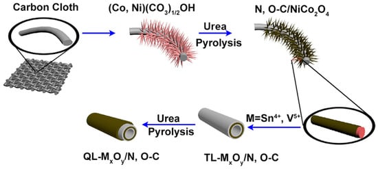
Figure 8.
Schematic illustrating the formation process of the quadruple-layered metal oxide/nitrogen, oxygen-doped carbon (QL-MxOy/N,O–C) nanotube array electrode. Reproduced with permission from [63] Copyright © 2020, Elsevier B.V.
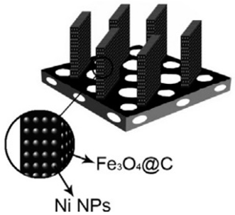
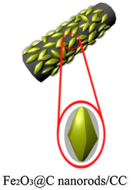
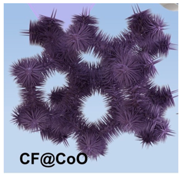
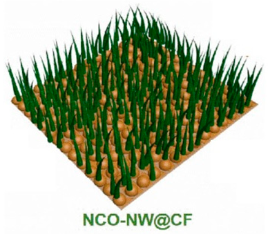
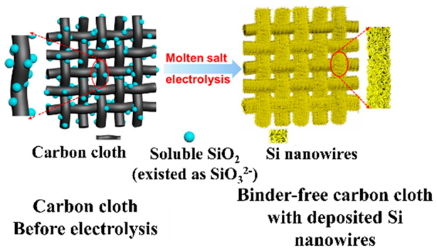
As other methods include, for example, BD-free SnS (observed discharge capacity: 967 mAhg−1), anodes can be prepared by magnetron sputtering [64]. NiO (observed discharge capacity: 638 mAhg−1) nanowalls were prepared on Ni foam (NF) via plasma-assisted oxidation of the CC of NF surfaces [65]. The oxidation of titanium (Ti) as a CC substrate to form a titanium oxide anode has also been proposed [66]. Several studies have shown that by etching the surface of germanium metal (Ge, 1624 mAhg−1 for Li22Ge5 alloy) produced by plasma-enhanced CVD with hydrogen fluoride, the surface area of Ge anodes can be increased, and the utilization efficiency of Ge anodes can be improved [67]. For example, a Si (observed discharge capacity: 711 mAhg−1) anode was fabricated by depositing a Si layer on carbon cloth using molten salt electrolysis [68].
A method for fixing cathode and anode EAMs by growing EAMs from the surface of CCs, which eliminates the use of a BD, is excellent in terms of electron and ion transfer. However, changes in the volume of the EAM during charging and discharging have a very high risk of disrupting electron and ion transfer paths. Coating the surface of the EAM layer with a carbon material, as described above, moderates the disruption of electron and ion transfer paths due to volume changes in the EAM layer [62,63]. Although BD is crucial for responding to volume changes, the contribution of a solid electrolyte layer is also considered a method for mitigating the deformation of the EAM layer without using BDs. When the fibrous EAM particles of VSe2 (with an observed discharge capacity of 421 mAhg−1) for anodes are fixed on N-doped carbon nanofiber (NCNF) surfaces as a CC, these particles come into contact with a quasisolid electrolyte layer and the quasisolid electrolyte changes in response to the volume change in the EAM layer. A mechanism was constructed to ensure that contact with the EAM particles was always maintained (Figure 9) [69].
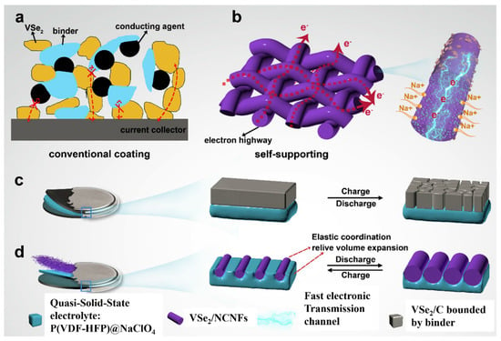
Figure 9.
(a,b) Electron transport path in a conventional coating electrode and VSe2/NCNFs, respectively; (c) changes in the charge/discharge process of powder materials bonded by BD; (d) changes in BD-free VSe2/NCNFs and elastic quasisolid electrolyte during the charge/discharge process. Reproduced with permission from [69] Copyright © 2020, Elsevier B.V.
In addition to the attempts described above, efforts have been made to synthesize EAMs directly on CC surfaces using various fabrication methods and materials. These results are summarized in Table 1.

Table 1.
Summary of BD-free electrodes in which EAMs were formed on CCs. Reproduced with permission from [70] Copyright © 2015, Elsevier B.V, [71] Copyright 2016, Elsevier B.V, [72] Copyright © 2016, Elsevier B.V, [73] Copyright © 2022, Elsevier B.V, [74] Copyright © 2023 WILEY-VCH Verlag GmbH & Co. KGaA, Weinheim., [75] Copyright © 2014 WILEY-VCH Verlag GmbH & Co. KGaA, Weinheim., [76] Copyright © 2021 WILEY-VCH Verlag GmbH & Co. KGaA, Weinheim., [77] Copyright © 2022 WILEY-VCH Verlag GmbH & Co. KGaA, Weinheim and [78] Copyright © 2018 American Chemical Society and [79] Copyright © 2017, Elsevier B.V.
4.2. Retention of Active Materials in a Conductive Three-Dimensional Matrix
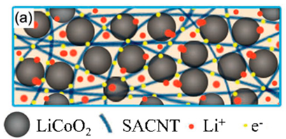
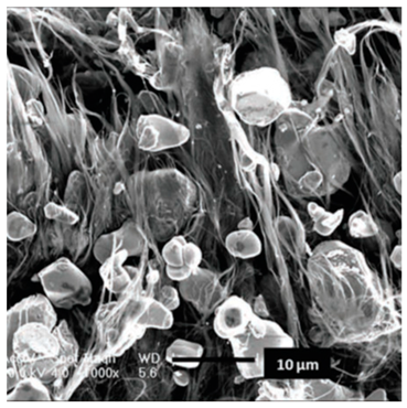
The EAM falls off the electron conduction path, causing deterioration in battery performance. In particular, an electron-conductive path is extremely difficult to maintain in the cathode and anode layers when the volume of the EAM is repeatedly increased or decreased because of charging or discharging. An effective method for inhibiting dropout from the conductive path is to confine EAM particles in a three-dimensional matrix with electronic conductivity. The electron-conducting and three-dimensional matrix must have voids spaced at intervals of several micrometers or less to hold EAM particles and must be inexpensive, so carbon materials are mainly used. The three-dimensional matrix structure is maintained by van der Waal’s forces between the carbon materials.
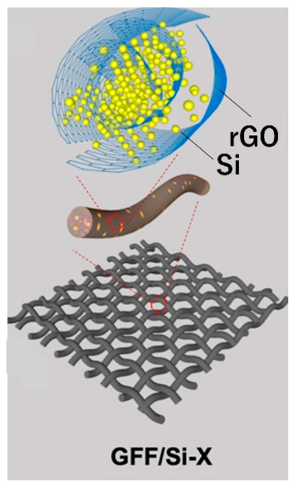
Zhang et al. proposed a typical method for confining Si particles in a carbon matrix [80]. After GO, CNTs, carbon nanofibers (CNFIs), polyvinylpyrrolidone (PVP), and Si particles are dispersed in a solution, a three-dimensional structure is formed in the solution through self-organization of the dispersed materials. These structures are extracted using a freeze-drying method. By firing the three-dimensional structure at high temperature under nitrogen, the main skeleton of the structure is carbonized, therefore forming a structure into which Si particles are incorporated. The membrane constructed from this structure had excellent flexibility and did not break even when bent or folded (Figure 10). This membrane was investigated as a Si anode, and the results showed a high capacity of 2250 mAhg−1 even after 100 cycles. Electrophoretic deposition has also been proposed as a method for creating a three-dimensional structure of EAM particles and carbon material dispersed in a solution [81]. One method uses a filtered dispersed layer to create an electrode by filtering EAM particles and an electronically conductive carbon material dispersed in a solution [82,83].
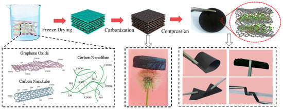
Figure 10.
Fabrication process of the RGO@CNTs@CNFIs@Si BD-free electrode. Reproduced with permission from [80] Copyright © 2023, Elsevier B.V.
Moreover, various methods have been devised to create three-dimensional structures that confine EAMs. The use of melamine resin (Basotect, BASF SE, Ludwigshafen am Rhein, Germany) as a three-dimensional carbon material has been proposed. Heat treatment of the melamine resin at 1000 °C results in the formation of a three-dimensional structure of nitrogen-containing, electronically conductive carbon material. After the Si particles and polyacrylonitrile (PAN) are incorporated into this structure, heat treatment is performed again to incorporate the Si particles into the structure (Figure 11) [84].

Figure 11.
Schematic of the preparation of carbon foam/Si composites. Reproduced with permission from [84] Copyright © 2016, American Chemical Society.
Electrospinning is also frequently used, for example, to create fiber-shaped materials using carbon materials [85]. The fiber shape was created by electrospinning using a mixture of the fiber raw material and EAM particles. By stacking fiber-shaped objects three-dimensionally, a three-dimensional structure with many voids is formed. By carbonizing the fiber-shaped main skeleton, an electronically conductive carbon frame is formed. EAM particles are strongly fixed inside or on the surface of the three-dimensional structure [86] (Figure 12).

Figure 12.
Schematic of the synthetic route to silicon oxide nanotubes (SNTs)@CNFs. Reproduced with permission from [86] Copyright © 2022, Elsevier B.V.
Furthermore, a method that changes the electron spinning method to create a structure in which EAM particles are contained within a fiber and surrounded by carbon material has been proposed (Figure 13). The Si anodes produced by these methods exhibited an initial discharge capacity of 1384 mAhg−1 during charge–discharge cycles at 3C and a discharge capacity of 721 mAhg−1 after 300 cycles. This structure improves the problem of performance deterioration caused by volume changes associated with charging and discharging [87]. Table 2 summarizes other examples.
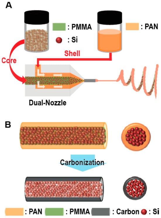
Figure 13.
Schematic of the electrospinning and carbonization steps. (A) Electrospinning process using a dual nozzle. Poly(methyl methacrylate) (PMMA) solutions containing Si particles and a PAN solution were injected into the core and shell channels of the nozzle, respectively. (B) After electrospinning, stabilization and carbonization steps were employed to construct the core−shell 1D fibers comprising Si particles–C. Reproduced with permission from [87] Copyright © 2012, American Chemical Society.

Table 2.
Summary of BD-free electrodes in which EAMs were confined in three-dimensional conductive materials. Reproduced with permission from [88] Copyright © 2013, American Chemical Society, [89] Copyright © 2020, WILEY-VCH Verlag GmbH & Co. KGaA, Weinheim, [90] Copyright © 2013, American Chemical Society, [91] Copyright © 2017, WILEY-VCH Verlag GmbH & Co. KGaA, Weinheim, [92] Copyright © 2021, WILEY-VCH Verlag GmbH & Co. KGaA, Weinheim and [93] Copyright © 2012, WILEY-VCH Verlag GmbH & Co. KGaA, Weinheim.
4.3. Formation of EAM Layer Using Interactions
Many methods for making electrodes by forming EAMs into fibers [94] or particles [95] and forming EAM layers through interactions between materials have been reported. In particular, this approach is frequently used to create EAMs in the form of fibers. Many reports are available on the use of the abovementioned electrospinning methods to create fibrous EAMs [96]. In addition to carbon anode materials [96], the fibrous materials SnSe [97], Sb2Se3 [98], and Ga2O3 [99] have also been synthesized and examined. A fibrous EAM can be created by chemical synthesis without using electrospinning, and an EAM layer can be formed without using a BD through the interaction of the fibrous EAM [100].
The study results showed that BD-free electrodes were created by forming EAM layers via a layer-by-layer process using a spray coating method in which a slurry prepared by dispersing the EAM of lithium titanate oxide (LTO, Li4Ti5O12), a conductive enhancer (Super P (SP)), and a thickener of carboxymethyl cellulose (CMC) in a solvent is ejected from a nozzle (Figure 14) [101]. Unlike in the conventional method for slurry casting, layer-by-layer EAM layers are formed, making it possible to form a film through interactions between particles. It has been reported that using this method, completely additive-free electrodes can be created without adding CA or thickeners. Even when the electrodes were bent, the EAM did not fall off, or the EAM layer separated from the CCs [101].
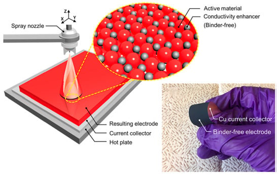
Figure 14.
Schematic for spray coating of the BD-free electrode over a large area CC. The magnified cartoon indicates the idealized arrangement of solid constituents within the BD-free electrode. Right-hand photograph of an as-fabricated BD-free electrode withstanding bending and flexing by hand. Reproduced with permission from [101] Copyright © 2023, Elsevier B.V.
In lithium-sulfur batteries, the typical method for preparing the positive electrode is to mix sulfur and a conductive additive with polyacrylonitrile, and then sinter it to finally bond the polyacrylonitrile to the matrix, producing a binder-free positive electrode, which achieves improved energy density [102].
4.4. Three-Dimensional Structure of Active Materials
If the bulk EAM is used, the use of a BD is unnecessary. However, in this case, the mass transfer of lithium ions (Li+) within the bulk material becomes slow, resulting in a lower utilization efficiency of the bulk material during the charging and discharging process. To avoid reducing the mass transfer rate of Li+ using bulk materials, three-dimensional methods are being used for the bulk materials.
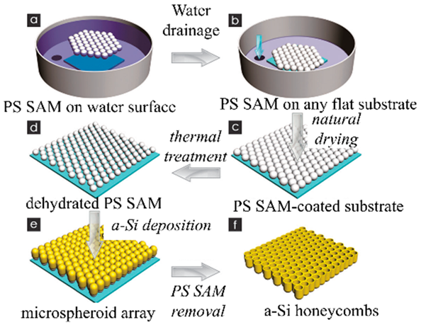
Lao et al. proposed the three-dimensional structure of SnO2/Bi2O3, which is considered a promising LIB anode material because of its high theoretical specific capacities of 782 and 690 mA h g−1, respectively, environmental friendliness, natural richness, and low cost [103]. The SnO2/Bi2O3 bulk materials have a three-dimensional ordered inverse opal (IO) heterojunction structure and form on an NF. Polystyrene (PS) particles were used as the soft template material. Initially, a structure comprising regularly stacked PS particles was formed. A slurry containing Sn ions and bismuth (Bi) ions filled the gaps in a structure in which polystyrene particles were stacked. The entire structure containing the slurry was then fired in air to eliminate the polystyrene particles and leave behind the IO structure of Sn and Bi oxides (Figure 15). The IO structure anode exhibited a discharge capacity of approximately 493 mAhg−1 after 500 cycles at a current density of 1000 mAg−1.

Figure 15.
Schematic of the synthesis process of SnO2/Bi2O3/NF IOs. Reproduced with permission from [103] Copyright © 2022, Elsevier B.V.
The three-dimensional structure of the EAM is based, for example, on a nanoporous structure of titanium oxide using Ti microarc oxidation (MAO). Through a hydrothermal reaction, a three-dimensional TiO2-x anode material was generated [66]. Anodes with a honeycomb structure of titanium oxide have also been created by anodizing a Ti substrate [104].
A chemical reaction within the nanotube array of porous titanium oxide formed by anodizing Ti creates a one-dimensional stacked structure of LTO particles, which facilitates the movement of Li+ to the EAM particle surface under construction. Specifically, LTO is formed by the chemical doping of Li+ into TiO2 nanotube arrays (Figure 16) [105]. Surprisingly, the LTO anode formed using these methods had excellent mechanical flexibility and robustness and a volumetric capacity of 304 mAhcm−3 at a current density of 50 mAcm−3. As another example, a structure is formed by stacking sea urchin-like iron oxide (Fe2O3) particles with robust adhesion among the particles and between the particles and the Ti CC [106].
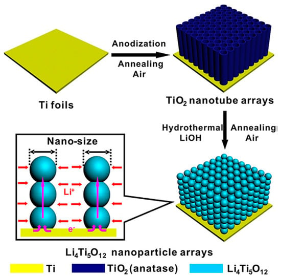
Figure 16.
Schematic illustrating the fabrication of self-supporting beaded stream-like LTO (BLTO) nanoparticles. Reproduced with permission from [105] Copyright © 2016, WILEY-VCH Verlag GmbH & Co. KGaA.
Koura et al. proposed a method for creating BD-free graphite films by electrophoretic electrodeposition of graphite particles. Charged graphite particles are electrodeposited on the electrodes because of the potential difference between the electrodes so that the electrostatic repulsion between the electrodeposited particles can be overcome and the graphite particles can be strongly aggregated by intermolecular forces [107].
5. Conductive Additive-Free Electrodes
Most examples of CA-free electrodes have been reported as success stories, often involving the confinement of EAMs within three-dimensional electronically conductive structures such as carbon materials or metal foams, as described in the chapter on BD-free electrodes [87,101,105]. The meaning of CA-free electrodes depends on whether the three-dimensional electron-conductive structure is considered a CA or a CC; here, this structure is considered a CC. With this in mind, research on CA-free electrodes will be described. Naturally, even when an EAM that grows from the surface of a CC and is strongly electronically bonded to the CC has a high electronic conductivity, it is unnecessary to add CAs to cathodes and anodes [108]. As mentioned above, there are also cases where EAM particles are laminated on a CC by electrophoretic deposition, etc., and the EAM particles are strongly bonded by interactions to form an EAM layer, therefore realizing a BD-free electrode [109]. Hereinafter, examples of BD-free electrodes that do not fall under these concepts are described.
Lestriez et al. reported that the rate characteristics were improved simply by applying a carbon coating to the surface of a CC without adding a CA to the EAM layer (Figure 17) [110]. This effect indicates that the resistance to electron conduction between the EAM layer and the CC interface is greater than the resistance to electron conduction between particles (or in the EAM layers). By coating the surface of CC with carbon, which has a high electronic conductivity, the interfacial resistance between the EAM layer and the CC decreases.

Figure 17.
Discharge curves and a schematic illustrating differences in the structure of cathodes with and without carbon black (CB) additives. Reproduced with permission from [110] Copyright © 2018, Elsevier B.V.
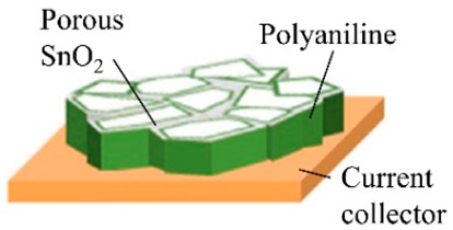
A method in which the electrode surface is covered with an electronically conductive polymer to cover the spaces between particles of the EAM has been proposed. This electronically conductive polymer acts as a BD. The conductive polymer takes the form of a spider web that covers the electrode surface and is a polymer salen-type Ni(II) complex, poly[Ni(CH3-salen)]. The polymer chains in the poly[Ni(Schiff)] films are additionally organized in stacks through donor−acceptor interactions between the metal ion of one fragment and the ligand of another. The oxidation/reduction of poly[Ni(Schiff)] films is a ligand-based process wherein charge transfer occurs along the polymer chains and between stacked chains through the phenyl rings of the ligands, with the metal ion acting as an innocent bridge between phenolate moieties. The lithium iron phosphate (LFP, LiFePO4) cathode in which the polymer chains covered the LFP cathode surfaces showed superior performance in terms of cycle stability and rate characteristics compared to when carbon CA was used (Figure 18) [111].
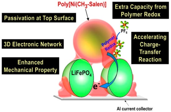
Figure 18.
Multiple roles of poly[Ni(CH3-salen)] in carbon-free cathodes. Reproduced with permission from [111] Copyright © 2019, American Chemical Society.
The high electronic conductivity of the EAM layers is difficult to ensure without adding CAs to the layers. Particularly in the case of organic batteries using an organic compound with poor electronic conductivity, not adding CA poses a serious problem in terms of electronic conductivity. However, adding a CA to the EAM layers is disadvantageous because of energy density issues, and in the case of organic batteries, the capacity of the EAM is still small, so the original capacity of the EAM can be maintained without adding a CA. There is a desire to achieve this goal in terms of performance. To solve this problem, in organic battery research, attempts are being made to utilize the properties of organic materials to skillfully select EAMs and three-dimensionally arrange them in an electron transport system.
The first possibility is to incorporate molecular structures capable of redox reactions for charging and discharging into electron-conductive polymers [112] or to bond molecules capable of redox reactions to polymer chains [113]. If the electron-conductive polymer portion is too large, the energy density will decrease, but one advantage is that elution from the electrode is suppressed by chemically fixing the redox reaction site. In some cases, the electron-conductive polymer itself acts as a redox site and becomes an EAM without containing a CA on the electrode surface [114].
Instead of electron-conducting polymers, it has been proposed to use organic charge-transfer (CT) complexes to ensure the high electronic conductivity of the EAM layer [115]. Following the abovementioned research, Honma et al. proposed the use of two types of CT complexes to improve the limited electronic conductivity of one type of CT complex. They also reported that electronic conductivity is maintained throughout the charging and discharging process [116]. They stated that by imparting electronic conductivity to the EAM layer using this method, they realized electrical conductivity relays over a wide range of areas (Figure 19).
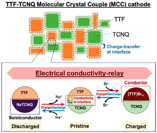
Figure 19.
Schematic of the relay of electrical conductivity via the charge-transfer phenomenon and organic radical salts using tetrathiafulvalene (TTF), tetracyanoquinodimethane (TCNQ), and an aqueous NaBr electrolyte. Reproduced with permission from [116] Copyright © 2020, American Chemical Society.
The abovementioned system using a charge-transfer (CT) complex simply mixes the CT complex in the EAM layer, but methods have also been proposed in which electron conductivity is imparted using an aggregate of organic materials with a three-dimensional structure. Perylene tetracarboxylic diimide (PTCDI) was self-assembled into nanofibers, the molecules were stacked with regularly arranged molecules, and electron transfer pathways were also effectively formed. Consequently, these materials can function as aqueous flexible sodium ion storage devices (AFSISDs) by improving electronic conductivity and achieving stability [117]. In addition, the EAM layer of perylene diimide (PDI) derivatives, in which PDI derivatives have higher electronic conductivity due to the supramolecular structure on the column, can function without CAs [118]. Although it is not an organic battery, a metal-organic framework (MOF) structure composed of Cu ions and organic linker molecules of nitrogen-rich multidentate 2-(1H-1,2,4-triazol-1-yl)pyridine has been proposed as an EAM with electronic conductivity [119].
Recently, liquid metals (LM) have attracted attention for their self-healing effects, and examples of research on LMs as electrode materials are numerous [120,121,122]. Another feature of the use of these materials is that since they are metals with high electronic conductivity, CA does not need to be added.
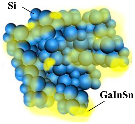
Research on the fluidity characteristics of LMs has shown that they can be applied as CAs for Si anodes, which repeatedly swell and contract during charge and discharge cycles [123]. The LM used is a GaInSn alloy (Figure 20). The capacity after 1500 cycles was 968 mAh/g, and the capacity retention rate was 81.3%. According to the rate test results, a capacity of 360 mAh/g was observed at 55 °C. An anode active material layer is prepared on a current collector using ML and Si anode active material. Although not described in detail, a conventional separator was used with 1 M LiPF6/ethylene carbonate, ethyl methyl carbonate, and dimethyl carbonate (EC:EMC:DMC = 1:1:1 vol%) electrolyte solution and were sandwiched between a lithium metal counter electrode and the prepared anode to create a half cell, and the electrode performance was evaluated.
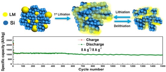
Figure 20.
Schemes of the charge–discharge process of the liquid metal (LM)/Si anode. Reproduced with permission from [123] Copyright © 2020, American Chemical Society.
6. Comparison of Si Anode Performance
Si is considered an anode material for high-capacity LIBs. However, as the Si particles repeatedly swell and contract during charging and discharging, the Si particles become finer and fall from the conduction path of the EAM layer, reducing charge and discharge capacity [124]. To prevent a decrease in capacity, various methods are being considered to add functionality to BDs [125,126] and CCs [127]. For electrodes that are free of CCs, BDs, and CAs, which are the subject of this review, it is extremely difficult to consistently achieve the performance of Si anodes. This chapter focuses on Si anodes and provides a summary of their performance.
6.1. Current Collector-Free Si Anodes
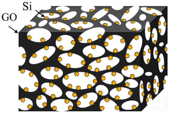
To prevent the Si particles from falling out of the conduction path of the EAM layer because of swelling and contraction of the Si particles during charging and discharging, a method for encapsulating Si particles in a three-dimensional structure made of carbon material has been frequently sought. This three-dimensional structure replaces the CC and becomes the basis of the electrode structure, so it is used as a freestanding electrode without a CC [128,129]. In addition to creating anodes by mixing Si particles with carbon materials, methods in which Si particles are surrounded by an electronically conductive carbon material to prevent them from falling off the conductive path have been proposed [130,131,132,133]. Fabricating the anode electrode by chemically etching the Si substrate and chemically positioning the template to create a three-dimensional Si structure has also been shown to result in high capacity and cycle stability [134,135,136]. Table 3 summarizes other examples of Si anodes.

Table 3.
Summary of CC-free Si anodes. Reproduced with permission from [128] Copyright © 2015, Elsevier B.V., [129] Copyright © 2016, WILEY-VCH Verlag GmbH & Co. KGaA, Weinheim, [130] Copyright © 2021, MDPI, [131] Copyright © 2021, American Chemical Society, [132] Copyright © 2021, Elsevier B.V., [133] Copyright © 2023, Royal Society of Chemistry, [134] Copyright © 2022, WILEY-VCH Verlag GmbH & Co. KGaA, Weinheim, [135] Copyright © 2013, American Chemical Society and [136] Copyright © 2014, Royal Society of Chemistry.
6.2. Binder-Free Si Anodes
Applying the method for covering Si particles with the carbon material described above also results in a BD-free electrode. Here, a description of a BD-free electrode manufactured using a method in which Si particles are held within an EAM layer using a different principle is given (Table 4).

Table 4.
Summary of BD-free Si anodes. Reproduced with permission from [68] Copyright © 2019, American Chemical Society, [137] Copyright © 2013, Springer Nature, [78] Copyright © 2018, American Chemical Society, [138] Copyright © 2014, Royal Society of Chemistry, [139] Copyright © 2021, WILEY-VCH Verlag GmbH & Co. KGaA, Weinheim and [140] Copyright © 2021, Elsevier B.V.
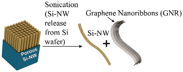
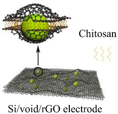
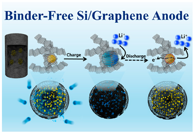
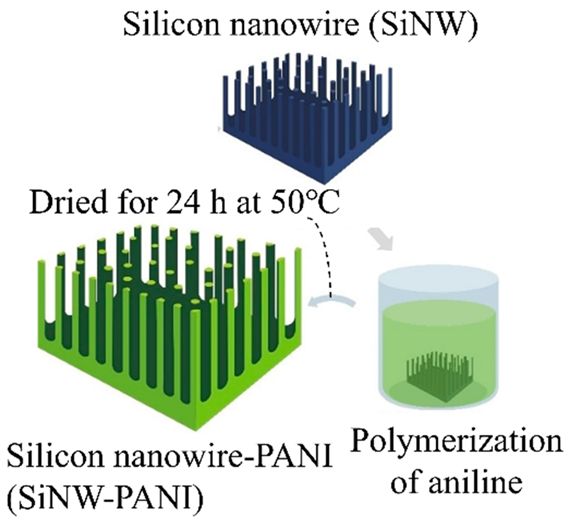
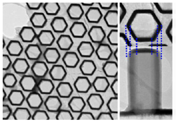
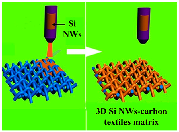
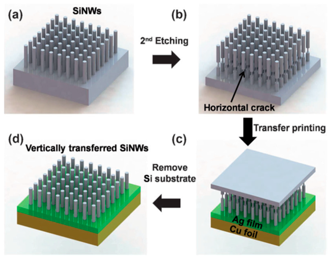
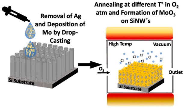
Methods for fixing Si particles and nanowires on the surface of carbon materials include electrochemical methods and spray methods [68,137]. Furthermore, the fabrication of a Si layer in which a charging reaction occurs (alloying of Li+ with Si) has been devised by three-dimensionally designing CCs that fix Si. When Si swells during the charging process, the volume change is alleviated, and space is available for the Si particles to swell so that they do not fall off the conductive path of the anode layer [78,138]. Si nanowire arrays are a very effective structure for Si anodes because when the Si swells, the space between the Si nanowires can be used as a relaxing space for the Si to increase in volume. Si nanowire arrays are often made from Si bulk materials [139,140].
6.3. Conductive Additive-Free Si Anodes
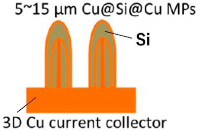
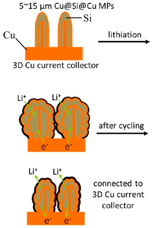
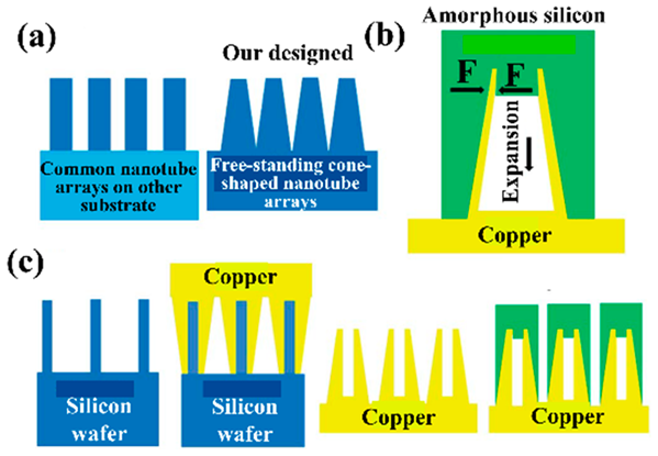
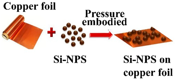
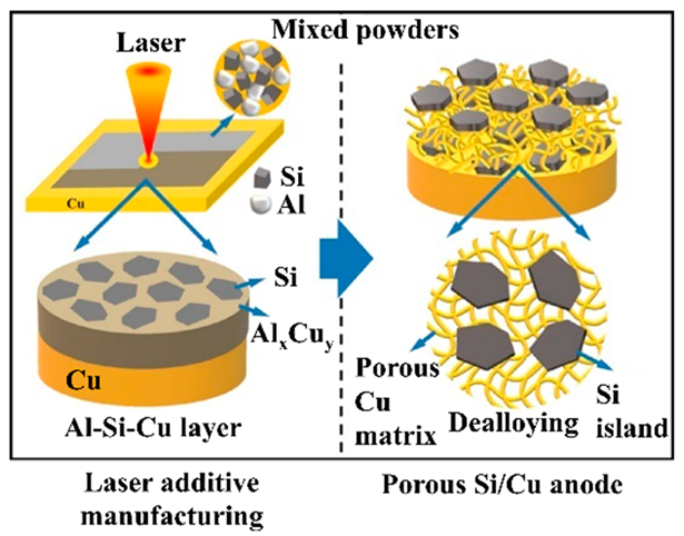
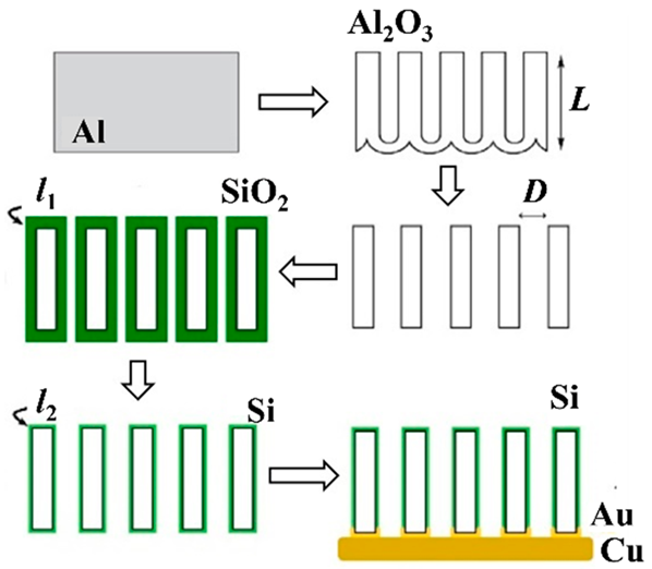
For example, when CAs are not added, Si particles are pressed onto a Cu CC to form an anode electrode. The Si particles are thought to sink into the Cu CC and hold the EAM as an electrode, and the cycle stability and rate characteristics are high [141]. As in the case of CC-free electrodes, if carbon materials are used as CCs if the EAMs and carbon materials are mixed and formed into an electrode, this electrode can be considered CA-free. As described above [123], if the electrode to which LM is added is CA-free because it does not contain carbon-based CAs, the Si anode prepared by adding LM is also CA-free. This idea is unique, and LMs used as EAMs can also be used as CA-free electrodes. Although these materials are not Si anodes, many similar papers have been published [142]. Considering the self-healing effect, a method in which the surface of Si particles is coated with a polymer with self-healing properties has also been proposed. Since Si particles are deposited on a carbon material with high electronic conductivity, no need exists to add CAs to provide electronic conductivity to anode layers, and the use of a coated polymer is an attempt to achieve self-healing [143]. To create a structure in which Si particles are arranged three-dimensionally, a layer containing a mixture of Si particles and Al particles is formed on CCs. Next, an Al–Cu alloy layer is formed using a laser, and the Si particles are fixed to the alloy layer. Finally, by selectively alloying Al, a structure can be created in which Si particles are anchored within a three-dimensional Cu frame [144]. Finally, there is an example of a method for arranging Si pillars perpendicular to the surface of CCs using a nanohole structure formed by anodic oxidation of Al as a template. Spaces exist between the pillars and inside the pillars when the Si swells, and the three-dimensional structure formed on the surface of the CCs does not collapse because of this swelling [145]. Table 5 summarizes the structure, manufacturing method, and performance of the CA-free electrodes.

Table 5.
Summary of CA-free Si anodes. Reproduced with permission from [141] Copyright © 2018, Elsevier B.V., [123] Copyright © 2018, Elsevier B.V., [143] Copyright © 2016, WILEY-VCH Verlag GmbH & Co. KGaA, Weinheim and [144] Copyright © 2020, American Chemical Society and [145] Copyright © 2021, Elsevier B.V.
6.4. Comprehensive Performance Comparison
Although the research content is contrary to the purpose of this review paper, there are highly cited papers, including reports on improving the BD [146], studies on the proportion of CAs added [147], and reports on encapsulating Si particles in carbon materials [148,149]. Figure 21 compares the performances of the abovementioned Si anodes, including those in these highly cited papers. Among the abovementioned references, those that describe the initial capacity and the capacity after increasing the number of cycles are selected, and the data are plotted in the figure.
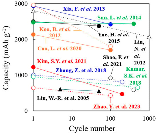
Figure 21.
Summary of the performances of Si anodes referred to in this paper, including the reference numbers [78,128,131,132,133,135,138,141,144,146,147,149].
Refs. [146,147,149] in the figure are highly cited papers. In the case of Si anodes that exhibit a relatively high capacity, refs. [135,138] reported the use of a three-dimensional structure of Si. These capacities are similar to the capacities and cycling stabilities of the materials in highly cited [146,149]. Conversely, many Si anodes with relatively low capacity have Si particles covered with carbon material. These results are thought to be due to the lack of space between the carbon material and the Si particles for the expansion of the Si particles. Furthermore, since the utilization rate of Si particles covered with carbon material is low, the access of Li+ to Si particles is considered disadvantageous. In addition, manufacturing Si anodes with a large capacity can be expected to require more effort and time. Although the results demonstrate the performance of a practical Si anode, doubts remain as to whether the manufacturing method is suitable for the mass production of batteries.
7. Comparison of the Toughness of the Electrodes
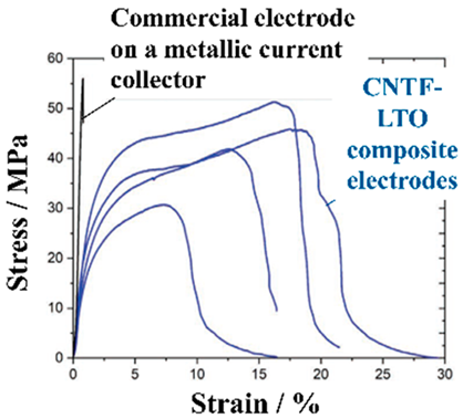
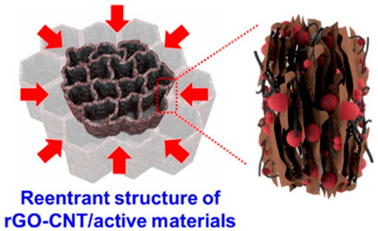
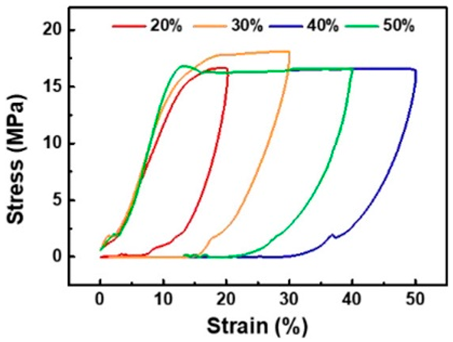
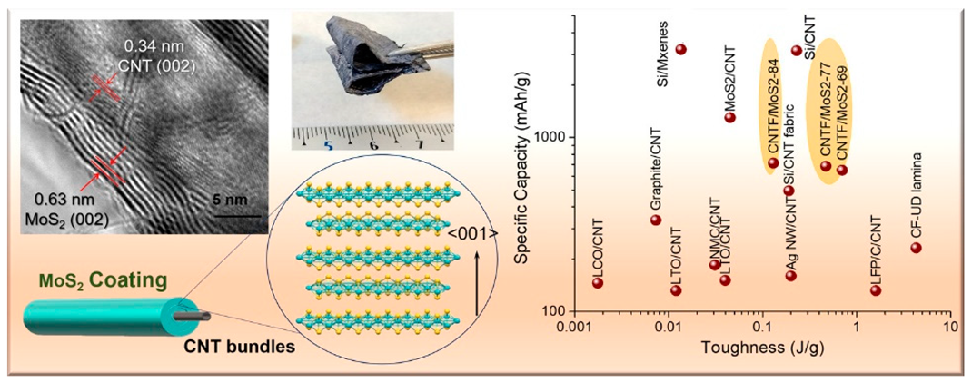
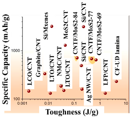
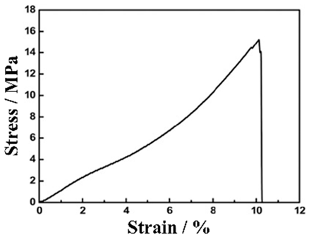
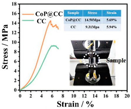
CC-, BD- and CA-free electrodes improve the energy density of a battery but also pose the problem of reduced electrode performance. Although attention is being given to charging and discharging performance, problems may arise with the mechanical durability (toughness) of the electrodes. Electrode toughness can be evaluated in various ways. For example, there is a test to determine whether the EAM does not peel off from the EAM layers when the electrode is bent or a peel test of the EAM layer from the electrodes. In a peel test, the toughness of the electrodes has different implications depending on whether the EAM layer peels off from the interface with the CCs or peeling occurs within the EAM layer. Park et al. evaluated the durability of electrodes made with conventional EAMs, BDs, and CAs without CCs. An electrode containing 63% LiCoO2 EAM, 26% BD, and 11% CA by weight has a maximum tensile strength of approximately 14 MPa and a tensile strain of 3.1% [150]. Many studies have investigated the toughness of electrodes using tensile stress–strain curves. Vilatela et al. presented results summarizing the toughness of the electrodes they investigated and the toughness of various electrodes shown in other papers [151]. Toughness can be evaluated from the properties obtained from tensile tests. The magnitude of the toughness corresponds to the area of the tensile stress–strain curves in the stress–strain diagrams.
As shown in Table 6, among the electrodes without CCs, the CNT fiber (CNTF) fabric reported by Vilatela et al. [151] has the greatest toughness. The toughness of this electrode is approximately 10 times greater than that of other electrodes. This strength can be attributed to the use of woven CNTF fabric as a carbon CC. The maximum stress of the electrode is approximately 20 MPa, and the strain at the maximum stress is approximately 17%. Not only is the electrode strong but also its energy density per weight has been improved by replacing CC with carbon (Figure 22).

Table 6.
Comparison of the combined electrochemical and mechanical properties of flexible electrodes in the planar configuration a. The reference numbers in the table have been changed to match the cited reference numbers in this paper. Reproduced with permission from [151] Copyright © 2019, American Chemical Society. The reference numbers in the table have been changed to match the cited reference numbers in this paper.
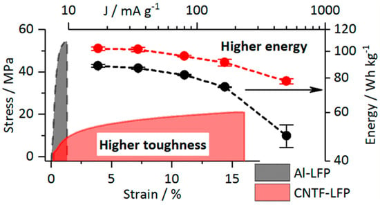
Figure 22.
Specific discharge energy (normalized to the total cell mass) vs. the current density (normalized to the LFP mass) and stress−strain curves of the Al-LiFePO4 (LFP) and carbon nanotube fiber (CNTF)-LFP electrodes. Reproduced with permission from [151] Copyright © 2019, American Chemical Society.
The toughness of electrodes can be considered the area between tensile stress–strain curves, so the toughness of electrodes shown in other papers was roughly estimated by calculating the area of the curves, and those electrodes with high toughness are listed in Table 6. The toughness can be roughly calculated as the following product: (maximum stress value) × (percentage of strain at maximum stress). In reality, standardization is needed, such as per electrode weight, but since little information is available at this time, standardization was not performed, and the values obtained with the above products were compared. The electrodes that are considered stronger are listed at the top of Table 7.

Table 7.
Summary of tough CC-, BD- and CA-free electrodes. Reproduced with permission from [161] Copyright © 2022, WILEY-VCH Verlag GmbH & Co. KGaA, Weinheim, [162] Copyright © 2020, American Chemical Society, [163] Copyright © 2021, American Chemical Society, [164] Copyright © 2018, American Chemical Society and [77] Copyright © 2022, WILEY-VCH Verlag GmbH & Co. KGaA, Weinheim.
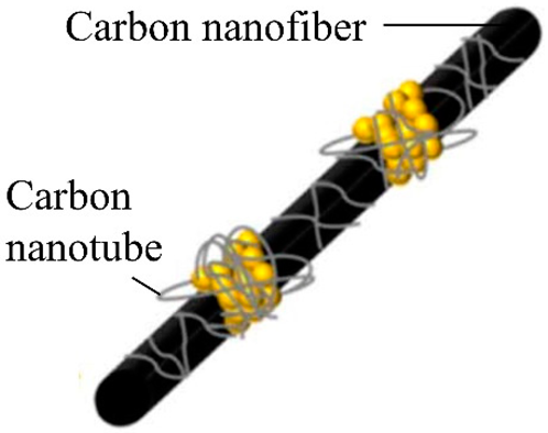
According to our literature review, the strongest electrode is an improved version of the CNTF fabric previously described by Vilatela et al. [161]. Electrodes using CCs woven with CNTs or CNTFs tend to have high toughness. Additionally, to prevent the EAMs from falling off the EAM layers, the EAM particles are often fixed to the surface of the CNTs or CNTFs. No particular fixation exists between the CNT or CNTF surface and the EAM particles, and the fixation of the EAM particles is strengthened by directly synthesizing the EAM layer on the surface of the CNT or CNTF [77,155,163]. In some cases, EAMs are simply encapsulated within an aggregate of flexible carbon material without being fixed to the surface of the carbon material [161,162].
8. Conclusions
To summarize this review article, the following points are listed:
- (1)
- In the current situation where there is a demand for improved energy density, one of the factors that must be addressed is the development of batteries that do not add collectors, binders, or conductive additives that cannot store energy.
- (2)
- The electrodes to be produced must not experience any degradation in performance compared to conventional batteries and must ensure long-term stability of performance and safety.
- (3)
- The functions of the CCs, BDs, and CAs are complementary to each other, so if one is removed from the electrode, the design must be such that the others take over its role.
- (4)
- To ensure electrode performance, it is important to select the structure of the electrode active material layer and the chemical substances that make it up, taking into consideration securing an electron transmission path with high electronic conductivity and a lithium-ion migration path, as well as stability over the long term and against electrochemical reactions.
Among various attempts that have been made to eliminate the use of CCs, BDs, and CAs that cannot charge and discharge electricity, in particular, carbon materials that serve as CCs and CAs are frequently used. Since CNTs and CNTFs have large surface areas, attempts have been made to directly fix EAMs to their surfaces, therefore eliminating the need for BDs. Another method is to incorporate EAM particles into a layer made of carbon material using the cohesive force between the carbon materials. It is believed that the type of carbon material used and the mixing ratio vary depending on which attribute is given importance, such as the electronic conductivity, fixation of the EAM, or formability of the entire EAM layer.
Furthermore, a consideration of factors such as the cost and availability of the materials that are used has recently been suggested. In addition to this trend, research is being conducted that ignores mass productivity and cost and focuses solely on improving performance, for example, by maximizing the capabilities of Si, and many studies that show impressive performance have been reported. Examples of these studies include Si wires arranged vertically against the CC. These wires are very effective in preventing the swelling and shrinking of Si, and the charge/discharge capacity is large and stable. However, this approach is thought to pose problems for the mass production of electrodes and practical use in batteries. Consequently, the mechanical durability of these batteries has not been examined and problems remain in their practical use. Taken together, these findings indicate that the appropriate direction for future research and development should involve the use of electrodes with carbon materials. Because electrodes made of carbon materials are highly durable and battery performance does not change even if these electrodes are bent or folded, it can be concluded that the mechanical durability of batteries developed in the future will be sufficient. Again, the biggest challenge going forward will be how to mass-produce these batteries. If these challenges can be overcome, CC-, BD-, and CA-free batteries will be commonplace in 10 years, and batteries that are completely free of these materials may be commonplace in 20 years.
In addition, the development trend of all-solid-state batteries is noteworthy. To realize all-solid-state batteries, the trend of not using CCs, BDs, and CAs may abandoned. To achieve the performance of electrodes in all-solid-state batteries, the use of any of these CCs, BDs, and CAs may be considered. Although the movement toward freeing CCs, BDs, and CAs may stagnate, the original approach for all-solid-state batteries is in this direction, so steady consideration in this direction is also necessary.
Author Contributions
Conceptualization, F.M. and M.F.; software, F.M.; validation, F.M. and M.F.; formal analysis, M.F.; investigation, F.M.; resources, F.M.; data curation, F.M.; writing—original draft preparation, F.M.; writing—review and editing, M.F.; visualization, M.F.; project administration, F.M. All authors have read and agreed to the published version of the manuscript.
Funding
This research received no external funding.
Data Availability Statement
The original contributions presented in the study are included in the article, further inquiries can be directed to the corresponding author.
Conflicts of Interest
The authors declare no conflict of interest.
Abbreviation
| AFSISD | Aqueous flexible sodium ion storage device |
| BD | Binder |
| BLTO | Beaded stream-like LTO |
| CA | Conductive additive |
| CB | Carbon black |
| CC | Current collector |
| CF | Carbon fiber |
| CF-CNT-P | Polymer (P)-based CF/CNT composite |
| CMC | Carboxymethyl cellulose |
| CNF | Cellulose nanofiber |
| CNFI | Carbon nanofiber |
| CNT | Carbon nanotube |
| CNTF | CNT fiber |
| CT | Charge-transfer |
| CVD | Chemical vapor deposition |
| EAM | Electrode active material |
| GO | Graphene oxide |
| IO | Inverse opal |
| LFP | Lithium iron phosphate |
| LiTFSI | Lithium bis(trifluoromethanesulfonyl)imide |
| LM | Liquid metal |
| LTO | Lithium titanate oxide |
| MAO | Microarc oxidation |
| MOF | Metal-organic framework |
| MWCNT | Multiwalled carbon nanotube |
| NCNF | N-doped carbon nanofiber |
| PAN | Polyacrylonitrile |
| PCL | Polycaprolactone |
| PDI | Perylene diimide |
| PLA | Polylactic acid |
| PMMA | Poly(methyl methacrylate) |
| PS | Polystyrene |
| PTCDI | Perylene tetracarboxylic diimide |
| PVDF | Polyvinylidene difluoride |
| PVdF-HFP | Poly(vinylidene fluoride-co-hexafluoropropylene) |
| PVP | Polyvinylpyrrolidone |
| Pyr14-TFSI | 1-butyl-1-methylpyrrolidinium bis-(trifluoromethanesulfonyl)imide |
| RGO | Reduced graphene oxide |
| SBR | Styrene–butadiene rubber |
| SNT | Silicon oxide nanotubes |
| TCNQ | Tetracyanoquinodimethane |
| TTF | Tetrathiafulvalene |
| VGCF | Vapor-grown carbon fiber |
References
- Winter, M.; Barnett, B.; Xu, K. Before Li ion batteries. Chem. Rev. 2018, 118, 11433–11456. [Google Scholar] [CrossRef] [PubMed]
- Zubi, G.; Dufo-López, R.; Carvalho, M.; Pasaoglu, G. The lithium-ion battery: State of the art and future perspectives. Renew. Sust. Energ. Rev. 2018, 89, 292–308. [Google Scholar] [CrossRef]
- Peters, J.F.; Baumann, M.; Zimmermann, B.; Braun, J.; Weil, M. The environmental impact of Li-Ion batteries and the role of key parameters—A review. Renew. Sust. Energ. Rev. 2017, 67, 491–506. [Google Scholar] [CrossRef]
- Liang, Y.; Zhao, C.-Z.; Yuan, H.; Chen, Y.; Zhang, W.; Huang, J.-Q.; Yu, D.; Liu, Y.; Titirici, M.-M.; Chueh, Y.-L.; et al. A review of rechargeable batteries for portable electronic devices. InfoMat 2019, 1, 6–32. [Google Scholar] [CrossRef]
- Deng, D. Li-ion batteries: Basics, progress, and challenges. Energy Sci. Eng. 2015, 3, 385–418. [Google Scholar] [CrossRef]
- Walter, M.; Kovalenko, M.V.; Kravchyk, K.V. Challenges and benefits of post-lithium-ion batteries. New J. Chem. 2020, 44, 1677. [Google Scholar] [CrossRef]
- Wu, B.; Chen, C.; Danilov, D.L.; Eichel, R.A.; Notten, P.H.L. All-solid-state thin film Li-ion batteries: New challenges, new materials, and new designs. Batteries 2023, 9, 186. [Google Scholar] [CrossRef]
- Li, M.; Lu, J.; Chen, Z.; Amine, K. 30 years of lithium-ion batteries. Adv. Mater. 2018, 30, 1800561. [Google Scholar] [CrossRef]
- Watanabe, T.; Tsuda, T.; Ando, N.; Nakamura, S.; Hayashi, N.; Soma, N.; Gunji, T.; Ohsaka, T.; Matsumoto, F. An improved pre-lithiation of graphite anodes using through-holed cathode and anode electrodes in a laminated lithium ion battery. Electrochim. Acta 2019, 324, 13484. [Google Scholar] [CrossRef]
- Lee, H.; Choi, W.; Park, H.S.; Kim, D.W. Realization of high loading density lithium polymer batteries by optimizing lithium-ion transport and electronic conductivity. ACS Appl. Mater. Interfaces. 2023, 15, 15298–15310. [Google Scholar] [CrossRef]
- Tsuda, T.; Ando, N.; Nakamura, S.; Ishihara, Y.; Hayashi, N.; Soma, N.; Gunji, T.; Tanabe, T.; Ohsaka, T.; Matsumoto, F. Improvement of high-rate discharging performance of LiFePO4 cathodes by forming micrometer-sized through-holed electrode structures with a pico-second pulsed laser. Electrochim. Acta 2019, 296, 27–38. [Google Scholar] [CrossRef]
- Bree, G.; Horstman, D.; Low, C.T.J. Light-weighting of battery casing for lithium-ion device energy density improvement. J. Energy Storage. 2023, 68, 107852. [Google Scholar] [CrossRef]
- Yamada, M.; Watanabe, T.; Gunji, T.; Wu, J.; Matsumoto, F. Review of the design of current collectors for improving the battery performance in lithium-ion and post-lithium-ion batteries. Electrochem 2020, 2, 124–159. [Google Scholar] [CrossRef]
- Zhang, L.; Qin, X.; Zhao, S.; Wang, A.; Luo, J.; Wang, Z.L.; Kang, F.; Lin, Z.; Li, B. Advanced matrixes for binder-free nanostructured electrodes in lithium-ion batteries. Adv. Mater. 2020, 32, 1908445. [Google Scholar] [CrossRef] [PubMed]
- Xu, Y.; Zhou, M.; Lei, Y. Nanoarchitectured array electrodes for rechargeable lithium- and sodium-ion batteries. Adv. Energy Mater. 2016, 6, 1502514. [Google Scholar] [CrossRef]
- Delaporte, N.; Ossonon, D.B.; Zaghib, K.; Bélanger, D. Fabrication of current collectors and binder-free electrodes on separators used in lithium-ion batteries. Batter. Supercaps 2020, 3, 638–646. [Google Scholar] [CrossRef]
- Hu, X.; Jin, Y.; Zhu, B.; Tan, Y.; Zhang, S.; Zong, L.; Lu, Z.; Zhu, J. Free-standing graphene-encapsulated silicon nanoparticle aerogel as an anode for lithium ion batteries. ChemNanoMat 2016, 2, 671–674. [Google Scholar] [CrossRef]
- Dçrr, T.S.; Fleischmann, S.; Zeiger, M.; Grobelsek, I.; de Oliveira, P.W.; Presser, V. Ordered mesoporous titania/carbon hybrid monoliths for lithium-ion battery anodes with high areal and volumetric capacity. Chem. Eur. J. 2018, 24, 6358–6363. [Google Scholar] [CrossRef]
- Whitehead, A.H.; Schreiber, M. Current collectors for positive electrodes of lithium-based batteries. J. Electrochem. Soc. 2005, 52, A2105–A2113. [Google Scholar] [CrossRef]
- Zhu, P.; Gastol, D.; Marshall, J.; Sommerville, R.; Goodship, V.; Kendrick, E. A review of current collectors for lithium-ion batteries. J. Power Sources 2021, 485, 229321. [Google Scholar] [CrossRef]
- Li, H.; Wang, L.; Song, Y.; Zhang, Z.; Zhang, H.; Du, A.; He, X. Significance of current collectors for high performance conventional lithium-ion batteries: A review. Adv. Funct. Mater. 2023, 33, 2305515. [Google Scholar] [CrossRef]
- Kataoka, R.; Oda, Y.; Inoue, R.; Kitta, M.; Kiyobayashi, T. High-strength clad current collector for silicon-based negative electrode in lithium ion battery. J. Power Sources 2016, 301, 355–361. [Google Scholar] [CrossRef]
- Myunga, S.-T.; Sasaki, Y.; Sakurada, S.; Sun, Y.-K.; Yashiro, H. Electrochemical behavior of current collectors for lithium batteries in non-aqueous alkyl carbonate solution and surface analysis by ToF-SIMS. Electrochim. Acta 2009, 55, 288–297. [Google Scholar] [CrossRef]
- Yao, Y.; Jiang, F.; Yang, C.; Fu, K.K.; Hayden, J.; Lin, C.-F.; Xie, H.; Jiao, M.; Yang, C.; Wang, Y.; et al. Epitaxial welding of carbon nanotube networks for aqueous battery current collectors. ACS Nano 2018, 12, 5266–5273. [Google Scholar] [CrossRef] [PubMed]
- Luo, W.; Hayden, J.; Jang, S.-H.; Wang, Y.; Zhang, Y.; Kuang, Y.; Wang, Y.; Zhou, Y.; Rubloff, G.W.; Lin, C.-F.; et al. Highly conductive, light weight, robust, corrosion resistant, scalable, all-fiber based current collectors for aqueous acidic batteries. Adv. Energy Mater. 2018, 8, 1702615. [Google Scholar] [CrossRef]
- Wang, M.; Le, A.V.; Shi, Y.; Noelle, D.J.; Qiao, Y. Heterogeneous current collector in lithium-ion battery for thermal-runaway mitigation. Appl. Phys. Lett. 2017, 110, 083902. [Google Scholar] [CrossRef]
- Ma, Y.; Ma, J.; Cui, G. Small things make big deal: Powerful binders of lithium batteries and post-lithium batteries. Energy Stor. Mater. 2019, 20, 146–175. [Google Scholar] [CrossRef]
- Costa, C.M.; Cardoso, V.F.; Martins, P.; Correia, D.M.; Gonçalves, R.; Costa, P.; Correia, V.; Ribeiro, C.; Fernandes, M.M.; Martins, P.M.; et al. Smart and multifunctional materials based on electroactive poly(vinylidene fluoride): Recent advances and opportunities in sensors, actuators, energy, environmental, and biomedical applications. Chem. Rev. 2023, 123, 11392–11487. [Google Scholar] [CrossRef]
- Buq, H.; Holzapfel, M.; Krumeich, F.; Veit, D.; Novák, P. Study of styrene butadiene rubber and sodium methyl cellulose as binder for negative electrodes in lithium-ion batteries. J. Power Sources 2006, 161, 617–622. [Google Scholar] [CrossRef]
- Zheng, H.; Yang, R.; Liu, G.; Song, X.; Battaglia, V.S. Cooperation between active material, polymeric binder and conductive carbon additive in lithium ion battery cathode. J. Phys. Chem. C 2012, 116, 4875–4882. [Google Scholar] [CrossRef]
- Zhang, L.; Wu, X.; Qian, W.; Pan, K.; Zhang, X.; Li, L.; Jia, M.; Zhang, S. Exploring more functions in binders for lithium batteries. Electrochem. Energy Rev. 2023, 6, 36. [Google Scholar] [CrossRef]
- Chen, B.; Zhang, Z.; Meng, Y.; Xiao, M. Polymeric binders used in lithium ion batteries: Actualities, strategies and trends. ChemElectroChem 2024, 11, e202300651. [Google Scholar] [CrossRef]
- Chou, S.-L.; Pan, Y.; Wang, J.-Z.; Liu, H.-K.; Dou, S.-X. Small things make a big difference: Binder effects on the performance of Li and Na batteries. Phys. Chem. Chem. Phys. 2014, 16, 20347–20359. [Google Scholar] [CrossRef] [PubMed]
- Dobryden, I.; Montanari, C.; Bhattacharjya, D.; Aydin, J.; Ahniyaz, A. Bio-based binder development for lithium-ion batteries. Materials 2023, 16, 5553. [Google Scholar] [CrossRef] [PubMed]
- Choi, S.; Kwon, T.-W.; Coskun, A.; Choi, J.W. Highly elastic binders integrating polyrotaxanes for silicon microparticle anodes in lithium ion batteries. Science 2017, 357, 279–283. [Google Scholar] [CrossRef] [PubMed]
- Li, J.-T.; Wu, Z.-Y.; Lu, Y.-Q.; Zhou, Y.; Huang, Q.-S.; Huang, L.; Sun, S.-G. Water soluble binder, an electrochemical performance booster for electrode materials with high energy density. Adv. Energy Mater. 2017, 7, 1701185. [Google Scholar] [CrossRef]
- Spahr, M.E.; Goers, D.; Leone, A.; Stallone, S.; Grivei, E. Development of carbon conductive additives for advanced lithium ion batteries. J. Power Sources 2011, 196, 3404–3413. [Google Scholar] [CrossRef]
- Shi, Y.; Wen, L.; Pei, S.; Wu, M.; Li, F. Choice for graphene as conductive additive for cathode of lithium-ion batteries. J. Energy Chem. 2019, 30, 19–26. [Google Scholar] [CrossRef]
- Kubarkov, A.V.; Babkin, A.V.; Drozhzhin, O.A.; Stevenson, K.J.; Antipov, E.V.; Sergeyev, V.G. Engendering high energy density LiFePO4 electrodes with morphological and compositional tuning. Nanomaterials 2023, 13, 1771. [Google Scholar] [CrossRef]
- Yap, J.W.; Wang, T.; Cho, H.; Kim, J.-H. Comparison of carbon-nanofiber and carbon-nanotube as conductive additives in Si anodes for high-energy lithium-ion batterie. Electrochim. Acta 2023, 446, 142108. [Google Scholar] [CrossRef]
- Entwistle, J.; Ge, R.; Pardikar, K.; Smith, R.; Cumming, D. Carbon binder domain networks and electrical conductivity in lithium-ion battery electrodes: A critical review. Renew. Sust. Energ. Rev. 2022, 166, 112624. [Google Scholar] [CrossRef]
- Lauro, S.N.; Broekhuis, B.G.; Papa, P.E.; Rastogi, A.; Burrow, J.N.; Ellison, C.J.; Mullins, C.B. A balancing act: Experimental insights into the volume fraction of conductive additive in lithium-ion battery electrodes. J. Electrochem. Soc. 2024, 171, 060525. [Google Scholar] [CrossRef]
- Baumgärtner, J.F.; Kravchyk, K.V.; Kovalenko, M.V. Navigating the carbon maze: A roadmap to effective carbon conductive networks for lithium-ion batteries. Adv. Energy Mater. 2024, 2400499. [Google Scholar] [CrossRef]
- Islam, J.; Chowdhury, F.I.; Uddin, J.; Amin, R.; Uddin, J. Review on carbonaceous materials and metal composites in deformable electrodes for flexible lithium-ion batteries. RSC Adv. 2021, 11, 5958–5992. [Google Scholar] [CrossRef] [PubMed]
- Zhang, J.; Cheng, W.; Zhang, R.; Zeng, T.; Lei, Y.; Zhao, H.; Luo, D. Investigation of carbon fiber anode materials for collector-free lithium-ion batteries. Int. J. Low Carbon Technol. 2022, 17, 1216–1222. [Google Scholar] [CrossRef]
- Ha, S.H.; Jeong, Y.S.; Lee, Y.J. Free standing reduced graphene oxide film cathodes for lithium ion batteries. ACS Appl. Mater. Interfaces 2013, 5, 12295–12303. [Google Scholar] [CrossRef]
- Rana, K.; Singh, J.; Lee, J.-T.; Park, J.H.; Ahn, J.-H. Highly conductive freestanding graphene films as anode current collectors for flexible lithium-ion batteries. ACS Appl. Mater. Interfaces 2014, 6, 11158–11166. [Google Scholar] [CrossRef]
- Fritsch, M.; Coeler, M.; Kunz, K.; Krause, B.; Marcinkowski, P.; Pötschke, P.; Wolter, M.; Michaelis, A. Lightweight polymer-carbon composite current collector for lithium-ion batteries. Batteries 2020, 6, 60. [Google Scholar] [CrossRef]
- Moyer, K.; Boucherbil, N.A.; Zohair, M.; Eaves-Rathert, J.; Pint, C.L. Polymer reinforced carbon fiber interfaces for high energy density structural lithium-ion batteries. Sustain. Energy Fuels 2020, 4, 2661–2668. [Google Scholar] [CrossRef]
- Sharma, J.; Demchuk, Z.; Polizos, G.; Kanbargi, N.; Tao, R.; Naskar, A.; Li, J. Aligned carbon fibers-carbon nanotube-polymer-based composite as lithium-ion battery current collector. J. Mater. Process Technol. 2023, 318, 118015. [Google Scholar] [CrossRef]
- Lu, L.; De Hosson, J.T.M.; Pei, Y. Three-dimensional micron-porous graphene foams for lightweight current collectors of lithium-sulfur batteries. Carbon 2019, 144, 713–723. [Google Scholar] [CrossRef]
- Phiri, I.; Kim, J.; Mpupuni, C.T.; Ssendagire, K.; Kim, J.-T.; Lee, Y.; Ryou, S.-Y. Keeping it simple: Free-standing, flexible cathodic electrodes for high rate, long cycling lithium batteries. ACS Appl. Energy Mater. 2022, 5, 13535–13543. [Google Scholar] [CrossRef]
- Zhao, P.; Li, W.; Fang, S.; Yu, J.; Yang, Z.; Cai, J. Cut-price fabrication of free-standing porous carbon nanofibers film electrode for lithium-ion batteries. Appl. Sci. 2019, 9, 1016. [Google Scholar] [CrossRef]
- Liang, S.; Pei, X.; Jiang, W.; Xu, Z.; Wang, W.; Teng, K.; Wang, C.; Fu, H.; Zhang, X. Free-standing dual-network red phosphorus@porous multichannel carbon nanofibers/carbon nanotubes as a stable anode for lithium-ion batteries. Electrochim. Acta 2019, 322, 134696. [Google Scholar] [CrossRef]
- Xiao, J.; Jin, Q.; Cang, R.; Gao, H.; Yao, J. Carbon-coated MXene nanofiber as a free-standing electrode for high-performance lithium-ion storage. Electrochim. Acta 2023, 451, 142289. [Google Scholar] [CrossRef]
- Cherian, S.K.; Kishore, K.R.; Reddy, S.; Sharma, C.S. Candle soot-embedded electrospun carbon nanofibers as a flexible and free-standing sulfur host for high-performance lithium−sulfur batteries. ACS Appl. Nano Mater. 2023, 6, 15574–15587. [Google Scholar] [CrossRef]
- Yang, Y.; Fu, W.; Bell, C.; Lee, D.-C.; Drexler, M.; Nuli, Y.; Ma, Z.-F.; Magasinski, A.; Yushin, G.; Alamgir, F.M. Iron phosphide confined in carbon nanofibers as a free-standing flexible anode for high-performance lithium-ion batteries. ACS Appl. Mater. Interfaces 2021, 13, 34074–34083. [Google Scholar] [CrossRef]
- Huang, J.; Wang, X.; Liu, J.; Sun, X.; Wang, L.; He, X. Flexible free-standing VO2(B) nanobelt films as additive-free cathode for lithium-ion batteries. Int. J. Electrochem. Sci. 2011, 6, 1709–1719. [Google Scholar] [CrossRef]
- Wang, J.; Wang, G.; Wang, H. Flexible free-standing Fe2O3/graphene/carbon nanotubes hybrid films as anode materials for high performance lithium-ion batteries. Electrochim. Acta 2015, 182, 192–201. [Google Scholar] [CrossRef]
- Zhao, S.; Li, M.; Wu, X.; Yu, S.H.; Zhang, W.; Luo, J.; Wang, J.; Geng, Y.; Gou, Q.; Sun, K. Graphene-based free-standing bendable films: Designs, fabrications, and applications. Mater. Today Adv. 2020, 6, 100060. [Google Scholar] [CrossRef]
- Li, Y.; Wu, X.; Wang, J.; Gao, X.; Hu, Y.; Wen, Z. Ni-less cathode with 3D free-standing conductive network for planar Na-NiCl2 batteries. Chem. Eng. J. 2020, 387, 124059. [Google Scholar] [CrossRef]
- Wei, X.; Li, W.; Shi, J.-a.; Gu, L.; Yu, Y. FeS@C on carbon cloth as flexible electrode for both lithium and sodium storage, ACS Appl. Mater. Interfaces 2015, 7, 27804–27809. [Google Scholar] [CrossRef] [PubMed]
- Sun, M.; Xie, Q.; Li, B.; Xiao, J.; Huang, Z. Design of quadruple-layered metal oxides/nitrogen, oxygen-doped carbon nanotube arrays as binder-free electrodes for flexible lithium-ion batteries. Electrochimi. Acta 2020, 363, 137201. [Google Scholar] [CrossRef]
- Chen, X.; Jiang, H.; Pei, Y.; Chen, Y.; Zeng, Y.; Guo, H. Binder-free ultrathin SnS with superior reversibility of conversion reaction for high-rate lithium ion batteries. J. Alloys Compd. 2021, 873, 159623. [Google Scholar] [CrossRef]
- Varghese, B.; Reddy, M.V.; Yanwu, Z.; Lit, C.S.; Hoong, T.C.; Rao, G.V.S.; Chowdari, B.V.R.; Wee, A.T.S.; Lim, C.T.; Sow, C.-H. Fabrication of NiO nanowall electrodes for high performance lithium ion battery. Chem. Mater. 2008, 20, 3360–3367. [Google Scholar] [CrossRef]
- Tao, W.; Wang, M.; Zhu, B.; Huo, W.; Yang, R.; Xiong, H.; Tang, H.; Wei, Z.; Wang, Y. In-situ synthesized binder-free flocculent TiO2-x film as anode for lithium-ion batteries. Electrochim. Acta 2020, 334, 135569. [Google Scholar] [CrossRef]
- Fugattini, S.; Gulzar, U.; Andreoli, A.; Carbone, L.; Boschetti, M.; Bernardoni, P.; Gjestila, M.; Mangherini, G.; Camattari, R.; Li, T.; et al. Binder-free nanostructured germanium anode for high resilience lithium-ion battery. Electrochim. Acta 2022, 411, 139832. [Google Scholar] [CrossRef]
- Weng, W.; Xiao, W. Electrodeposited silicon nanowires from silica dissolved in molten salts as a binder-free anode for lithium-ion batteries. ACS Appl. Energy Mater. 2019, 2, 804–813. [Google Scholar] [CrossRef]
- Wu, Y.; Zhong, W.; Tang, W.; Zhang, L.; Chen, H.; Li, Q.; Xu, M.; Bao, S.-j. Flexible electrode constructed by encapsulating ultrafine VSe2 in carbon fiber for quasi-solid-state sodium ion batteries. J. Power Sources 2020, 470, 228438. [Google Scholar] [CrossRef]
- Li, Z.; Zhao, H.; Wang, J.; Lv, P.; Zhang, Z.; Zeng, Z.; Xia, Q. 3D heterostructure Fe3O4/Ni/C nanoplate arrays on Ni foam as binder-free anode for high performance lithium-ion battery. Electrochim. Acta 2015, 182, 398–405. [Google Scholar] [CrossRef]
- Shen, Z.; Hu, Y.; Chen, Y.; Chen, R.; He, X.; Zhang, X.; Shao, H.; Zhang, Y. Controllable synthesis of carbon-coated Sn–SnO2–carbon-nanofiber membrane as advanced binder-free anode for lithium-ion batteries. Electrochim. Acta 2016, 188, 661–670. [Google Scholar] [CrossRef]
- Wang, X.; Zhang, M.; Liu, E.; He, F.; Shi, C.; He, C.; Li, J.; Zhao, N. Three-dimensional core-shell Fe2O3@carbon/carbon cloth as binder-free anode for the high-performance lithium-ion batteries. Appl. Surf. Sci. 2016, 390, 350–356. [Google Scholar] [CrossRef]
- Shin, N.; Kim, M.; Ha, J.; Kim, Y.-T.; Choi, J. Flexible anodic SnO2 nanoporous structures uniformly coated with polyaniline as a binder-free anode for lithium ion batteries. J. Electroanal. Chem. 2022, 914, 116296. [Google Scholar] [CrossRef]
- Liu, H.; Liu, R.; Ma, Y.; Wang, L.; Sun, C.; Xu, T.; Liu, H.; Wang, J. Cobalt oxide arrays anchored to copper foam as efficient binder-free anode for lithium ion batteries. ChemPhysChem 2023, 24, e202300290. [Google Scholar] [CrossRef] [PubMed]
- Lou, F.; Zhou, H.; Tran, T.D.; Buan, M.E.M.; Vullum-Bruer, F.; Rønning, M.; Walmsley, J.C.; Chen, D. Coaxial carbon/metal oxide/aligned carbon nanotube arrays as high-performance anodes for lithium ion batteries. ChemSusChem 2014, 7, 1335–1346. [Google Scholar] [CrossRef] [PubMed]
- Kakarla, A.K.; Narsimulu, D.; Yu, J.S. High capacity performance of NiCo2O4 nanostructures as a binder-free anode material for lithium-ion batteries. Int. J. Energy Res. 2021, 45, 13355–13364. [Google Scholar] [CrossRef]
- Yang, Y.; Xia, J.; Guan, X.; Wei, Z.; Yu, J.; Zhang, S.; Xing, Y.; Yang, P. In situ growth of CoP nanosheet arrays on carbon cloth as binder-free electrode for high-performance flexible lithium-ion batteries. Small 2022, 18, 2204970. [Google Scholar] [CrossRef]
- Zhang, Z.; Wang, Z.L.; Lu, X. Multishelled Si@Cu microparticles supported on 3D Cu current collectors for stable and binder-free anodes of lithium-ion batteries. ACS Nano 2018, 12, 3587–3599. [Google Scholar] [CrossRef]
- Yuan, W.; Luo, J.; Pan, B.; Qiu, Z.; Huang, S.; Tang, Y. Hierarchical shell/core CuO nanowire/carbon fiber composites as binder-free anodes for lithium-ion batteries. Electrochim. Acta 2017, 241, 261–271. [Google Scholar] [CrossRef]
- Ding, Y.; Li, P.; Wang, J.; Li, X.; Liu, Y.; Bai, H.; Zhang, H. Rationally designed rGO@CNTs@CNFs film as self-supporting binder-free Si electrodes for high-performance lithium-ion batteries. J. Colloid Interface Sci. 2023, 631, 249–257. [Google Scholar] [CrossRef]
- Yang, Y.; Li, J.; Chen, D.; Fu, T.; Sun, D.; Zhao, J. Binder-free carbon-coated silicon–reduced graphene oxide nanocomposite electrode prepared by electrophoretic deposition as a high-performance anode for lithium-ion batteries. ChemElectroChem 2016, 3, 757–763. [Google Scholar] [CrossRef]
- Zhai, J.; Lei, Z.; Sun, K.; Zhu, S. MXene enabled binder-free FeOF cathode with high volumetric and gravimetric capacities for flexible lithium ion batteries. Electrochim. Acta 2022, 423, 140595. [Google Scholar] [CrossRef]
- Tong, X.; Yang, B.; Li, F.; Gu, M.; Zhan, X.; Tian, J.; Huang, S.; Wang, G. Binder-free CoMn2O4 nanoflower particles/graphene/carbon nanotube composite film for a high-performance lithium-ion battery. Inorganics 2023, 11, 314. [Google Scholar] [CrossRef]
- Roy, A.K.; Zhong, M.; Schwab, M.G.; Binder, A.; Venkataraman, S.S.; Tomovicć, Z. Preparation of a binder-free three-dimensional carbon foam/silicon composite as potential material for lithium ion battery anodes. ACS Appl. Mater. Interfaces 2016, 8, 7343–7348. [Google Scholar] [CrossRef] [PubMed]
- Li, D.; Xia, J. Electrospinning of nanofibers: Reinventing the wheel? Adv. Mater. 2004, 16, 1151–1170. [Google Scholar] [CrossRef]
- Si, L.; Yan, K.; Li, C.; Huang, Y.; Pang, X.; Yang, X.; Sui, D.; Zhang, Y.; Wang, J.; Xu, C.C. Binder-free SiO2 nanotubes/carbon nanofibers mat as superior anode for lithium-ion batteries. Electrochim. Acta 2022, 404, 139747. [Google Scholar] [CrossRef]
- Hwang, T.H.; Lee, Y.M.; Kong, B.-S.; Seo, J.-S.; Choi, J.W. Electrospun core−shell fibers for robust silicon nanoparticle-based lithium ion battery anodes. Nano Lett. 2012, 12, 802–807. [Google Scholar] [CrossRef]
- Liu, Y.; Wang, W.; Gu, L.; Wang, Y.; Ying, Y.; Mao, Y.; Sun, L.; Peng, X. Flexible CuO nanosheets/reduced-graphene oxide composite paper: Binder-free anode for high-performance lithium-ion batteries. ACS Appl. Mater. Interfaces 2013, 5, 9850–9855. [Google Scholar] [CrossRef]
- Hu, B.; Zhou, X.; Xu, J.; Wang, X.; Yuan, N.; Ge, S.; Ding, J. Excellent rate and low temperature performance of lithium-ion batteries based on binder-free Li4Ti5O12 electrode. ChemElectroChem 2020, 7, 716–722. [Google Scholar] [CrossRef]
- Zhu, Y.; Han, X.; Xu, Y.; Liu, Y.; Zheng, S.; Xu, K.; Hu, L.; Wang, C. Electrospun Sb/C fibers for a stable and fast sodium-ion battery anode. ACS Nano 2013, 7, 6378–6386. [Google Scholar] [CrossRef]
- Fu, L.; Wang, X.; Ma, J.; Zhang, C.; He, J.; Xu, H.; Chai, J.; Li, S.; Chai, F.; Cui, G. Graphene-encapsulated copper tin sulfide submicron spheres as high-capacity binder-free anode for lithium-ion batteries. ChemElectroChem 2017, 4, 1124–1129. [Google Scholar] [CrossRef]
- Wang, Y.; Zhou, H.; Xiao, J.; Yuan, A. Graphene aerogel supported Fe-Co selenide nanocubes as binder-free anodes for lithium-ion batteries. Z. Anorg. Allg. Chem. 2021, 647, 1025–1030. [Google Scholar] [CrossRef]
- Luo, S.; Wang, K.; Wang, J.; Jiang, K.; Li, Q.; Fan, S. Binder-free LiCoO2 /carbon nanotube cathodes for high-performance lithium ion batteries. Adv. Mater. 2012, 24, 2294–2298. [Google Scholar] [CrossRef] [PubMed]
- Wang, T.; Shi, S.; Li, Y.; Zhao, M.; Chang, X.; Wu, D.; Wang, H.; Peng, L.; Wang, P.; Yang, G. Study of microstructure change of carbon nanofibers as binder-free anode for high-performance lithium-ion batteries. ACS Appl. Mater. Interfaces 2016, 8, 33091–33101. [Google Scholar] [CrossRef] [PubMed]
- Lee, D.; Lee, H.; Kim, Y.-T.; Lee, K.; Choi, J. Phase-tuned nanoporous vanadium pentoxide as binder-free cathode for lithium ion battery. Electrochim. Acta 2020, 330, 135192. [Google Scholar] [CrossRef]
- Jin, J.; Shi, Z.-q.; Wanga, C.-y. Electrochemical performance of electrospun carbon nanofibers as free-standing and binder-free anodes for sodium-ion and lithium-ion batteries. Electrochim. Acta 2014, 141, 302–310. [Google Scholar] [CrossRef]
- Xia, J.; Yuan, Y.; Yan, H.; Liu, J.; Zhang, Y.; Liu, L.; Zhang, S.; Li, W.; Yang, X.; Shu, H.; et al. Electrospun SnSe/C nanofibers as binder-free anode for lithium–ion and sodium-ion batteries. J. Power Sources 2020, 449, 227559. [Google Scholar] [CrossRef]
- Luo, W.; Calas, A.; Tang, C.; Li, F.; Zhou, L.; Mai, L. Ultralong Sb2Se3 nanowire-based free-standing membrane anode for lithium/sodium ion batteries. ACS Appl. Mater. Interfaces 2016, 8, 35219–35226. [Google Scholar] [CrossRef]
- Gao, Y.; Wang, B. Binder- and conductive additive-free Ga2O3 nanowires as a self-healing anode for lithium storage. Prog. Nat. Sci. Mater. Int. 2023, 33, 203–210. [Google Scholar] [CrossRef]
- Diem, A.M.; Fenk, B.; Bill, J.; Burghard, Z. Binder-free V2O5 cathode for high energy density rechargeable aluminum-ion batteries. Nanomaterials 2020, 10, 247. [Google Scholar] [CrossRef]
- Lee, S.H.; Grant, P.S. Spray fabrication of additive-free electrodes for advanced Lithium-ion storage technologies. J. Colloid Interface Sci. 2023, 651, 742–749. [Google Scholar] [CrossRef] [PubMed]
- Shi, C.; Takeuchi, S.; Alexander, G.V.; Hamann, T.; O’Neill, J.; Dura, J.A.; Wachsman, E.D. High sulfur loading and capacity retention in bilayer garnet sulfurized-polyacrylonitrile/lithium-metal batteries with gel polymer electrolytes. Adv. Energy Mater. 2023, 13, 2301656. [Google Scholar] [CrossRef]
- Zhang, R.; Fang, T.; Ni, L.; Zhu, Y.; Shen, Y.; Xie, A.; Lao, L. SnO2/Bi2O3/NF heterojunction with ordered macro/meso-pore structure as an advanced binder-free anode for lithium ion batteries. J. Electroanal. Chem. 2022, 907, 115894. [Google Scholar] [CrossRef]
- Huo, J.; Xue, Y.; Liu, Y.; Guo, S. Low-temperature preparation of mesoporous TiO2 honeycomb-like structure on TiO2 nanotube arrays as binder-free anodes for lithium-ion batteries. J. Electroanal. Chem. 2020, 863, 114088. [Google Scholar] [CrossRef]
- Huo, K.; Li, X.; Gao, B.; Wang, L.; Li, Q.; Peng, X.; Zhang, X.; Fu, J.; Chu, P.K. Self-supporting and binder-free anode film composed of beaded stream-like Li4Ti5O12 nanoparticles for high-performance lithium-ion batteries. ChemElectroChem 2016, 3, 1301–1305. [Google Scholar] [CrossRef]
- Cao, Y.; Zhang, A.-Q.; Luo, H.-W.; Gao, H.-L.; Yan, J.; Yan, Q.-Q.; Liu, Y.-M.; Zhang, Y. Hierarchical urchin-like Fe2O3 structures grown directly on Ti foils for binder-free lithium-ion batteries with fast charging/discharging properties. Inorg. Chem. Commun. 2020, 113, 107769. [Google Scholar] [CrossRef]
- Koura, N.; Etoh, K.; Idemoto, Y.; Matsumoto, F. Electrochemical behavior of graphite–lithium intercalation electrode in AlCl3–EMIC–LiCl–SOCl2 room-temperature molten salt. Chem. Lett. 2001, 30, 1320–1321. [Google Scholar] [CrossRef]
- Wang, Z.; Zeng, F.; Zhao, S.; Li, C.; Yang, W.; Leng, Z.; Wang, L.; Cheng, Y. In-situ fabricate highly ordered 3D Cervantite@TiO2 nanoarrays integrated electrode as additive-free anode for lithium/sodium-ion batteries. J. Power Sources 2022, 548, 232054. [Google Scholar] [CrossRef]
- Ha, D.-H.; Islam, M.A.; Robinson, R.D. Binder-free and carbon-free nanoparticle batteries: A method for nanoparticle electrodes without polymeric binders or carbon black. Nano Lett. 2012, 12, 5122–5130. [Google Scholar] [CrossRef]
- Busson, C.; Blin, M.-A.; Guichard, P.; Soudan, P.; Crosnier, O.; Guyomard, D.; Lestriez, B. A primed current collector for high performance carbon-coated LiFePO4 electrodes with no carbon additive. J. Power Sources 2018, 406, 7–17. [Google Scholar] [CrossRef]
- O’Meara, C.; Karushev, M.P.; Polozhentceva, I.A.; Dharmasena, S.; Cho, H.; Yurkovich, B.J.; Kogan, S.; Kim, J.-H. Nickel−salen-type polymer as conducting agent and binder for carbon-free cathodes in lithium-ion batteries, ACS Appl. Mater. Interfaces 2019, 11, 525–533. [Google Scholar] [CrossRef] [PubMed]
- Wang, H.; Emanuelsson, R.; Liu, H.; Mamedov, F.; Strømme, M.; Sjödin, M. A conducting additive-free high potential quinone-based conducting redox polymer as lithium ion battery cathode. Electrochim. Acta 2021, 391, 138901. [Google Scholar] [CrossRef]
- Friebe, C.; Zens, C.; Kupfer, S.; Schubert, U.S. Additive-free organic radical batteries prepared through electrochemical polymerization of TEMPO-decorated terthiophene. J. Phys. Chem. C 2023, 127, 1333–1344. [Google Scholar] [CrossRef]
- Chen, Z.; Yong, F.; Wang, Y.; Zhao, M.; Yu, F. Developing a p-toluenesulfonic acid monohydrate-assisted electrodeposition method to synthesize an additive-free polypyrrole cathode for high-rate stability and high gravimetric/volumetric capacity Li-ion batteries. ACS Sustain. Chem. Eng. 2023, 11, 144–154. [Google Scholar] [CrossRef]
- Lee, S.; Hong, J.; Jung, S.-K.; Ku, K.; Kwon, G.; Seong, W.M.; Kim, H.; Yoon, G.; Kang, I.; Hong, K.; et al. Charge-transfer complexes for high-power organic rechargeable batteries. Energy Storage Mater. 2019, 20, 462–469. [Google Scholar] [CrossRef]
- Fujihara, Y.; Kobayashi, H.; Takaishi, S.; Tomai, T.; Yamashita, M.; Honma, I. Electrical conductivity-relay between organic charge-transfer and radical salts toward conductive additive-free rechargeable battery. ACS Appl. Mater. Interfaces 2020, 12, 25748–25755. [Google Scholar] [CrossRef]
- Yang, L.; Wang, P.; Zhang, S.; Wang, Y.; Zang, L.; Zhu, H.; Yin, J.; Yang, H.Y. Flexible and additive-free organic electrodes for aqueous sodium ion batteries. J. Mater. Chem. A 2020, 8, 22791–22801. [Google Scholar] [CrossRef]
- Pignier, V.; Toumieux, S.; Davoisne, C.; Caroff, M.; Jamali, A.; Pilard, S.; Mathiron, D.; Cailleu, D.; Delattre, F.; Singh, D.P.; et al. Toward conductive additive free organic electrode for lithium-ion battery using supramolecular columnar organization. Small 2024, 20, 2305701. [Google Scholar] [CrossRef]
- Mishra, S.; Singh, M.K.; Pandey, D.; Rai, D.K.; Raghuvanshi, A. A two-dimensional semiconducting Cu(I)-MOF for binder and conductive additive-free supercapattery. J. Mater. Chem. A 2024, 12, 4534–4543. [Google Scholar] [CrossRef]
- Wei, C.; Fei, H.; Tian, Y.; An, Y.; Zeng, G.; Feng, J.; Qian, Y. Room-temperature liquid metal confined in MXene paper as a flexible, freestanding, and binder-free anode for next-generation lithium-ion batteries. Small 2019, 15, 1903214. [Google Scholar] [CrossRef]
- Deshpande, R.D.; Li, J.; Cheng, Y.-T.; Verbrugge, M.W. Liquid metal alloys as self-healing negative electrodes for lithium ion batteries. J. Electrochem. Soc. 2011, 158, A845–A849. [Google Scholar] [CrossRef]
- Ponnuru, H.; Marriam, I.; Rambukwella, I.; Zheng, J.-C.; Yan, C. Recent advances in liquid metals for rechargeable batteries. Adv. Funct. Mater. 2023, 2309706. [Google Scholar] [CrossRef]
- Han, B.; Yang, Y.; Shi, X.; Zhang, G.; Gong, L.; Xu, D.; Zeng, H.; Wang, C.; Gu, M.; Deng, Y. Spontaneous repairing liquid metal/Si nanocomposite as a smart conductive-additive-free anode for lithium-ion battery. Nano Energy 2018, 50, 359–366. [Google Scholar] [CrossRef]
- Zuo, X.; Zhu, J.; Müller-Buschbaum, P.; Cheng, Y.-J. Silicon based lithium-ion battery anodes: A chronicle perspective review. Nano Energy 2017, 31, 113–143. [Google Scholar] [CrossRef]
- Kwon, T.W.; Choi, J.W.; Coskun, A. The emerging era of supramolecular polymeric binders in silicon anodes. Chem. Soc. Rev. 2018, 47, 2145. [Google Scholar] [CrossRef] [PubMed]
- Zhao, Y.-M.; Yue, F.-S.; Li, S.-C.; Zhang, Y.; Tian, Z.-R.; Xu, Q.; Xin, S.; Guo, Y.-G. Advances of polymer binders for silicon-based anodes in high energy density lithium-ion batteries. InfoMat 2021, 3, 460–501. [Google Scholar] [CrossRef]
- Unno, H.; Nagata, T.; Fujimoto, N.; Fukuda, M. Fe-based metal foils for current collectors in Li-secondary batteries. Nippon Steel Gihou 2019, 412, 173–183. Available online: https://www.nipponsteel.com/tech/report/pdf/412-26.pdf (accessed on 9 September 2024).
- Yue, H.; Wang, S.; Yang, Z.; Li, Q.; Lin, S.; He, D. Ultra-thick porous films of graphene-encapsulated silicon nanoparticles as flexible anodes for lithium ion batteries. Electrochim. Acta 2015, 174, 688–695. [Google Scholar] [CrossRef]
- Salvatierra, R.V.; Raji, A.-R.O.; Lee, S.-K.; Ji, Y.; Li, L.; Tour, J.M. Silicon nanowires and lithium cobalt oxide nanowires in graphene nanoribbon papers for full lithium ion battery. Adv. Energy Mater. 2016, 6, 1600918. [Google Scholar] [CrossRef]
- Shao, J.; Yang, Y.; Zhang, X.; Shen, L.; Bao, N. 3D yolk–shell structured Si/void/rGO free-standing electrode for lithium-ion battery. Materials 2021, 14, 2836. [Google Scholar] [CrossRef]
- Shao, F.; Li, H.; Yao, L.; Xu, S.; Li, G.; Li, B.; Zou, C.; Yang, Z.; Su, Y.; Hu, N.; et al. Binder-free, flexible, and self-standing non-woven fabric anodes based on graphene/Si hybrid fibers for high-performance Li-ion batteries. ACS Appl. Mater. Interfaces 2021, 13, 27270–27277. [Google Scholar] [CrossRef] [PubMed]
- Kim, S.Y.; Kim, C.H.; Yang, C.-M. Binder-free silicon anodes wrapped in multiple graphene shells for high-performance lithium-ion batteries. J. Power Sources 2021, 486, 229350. [Google Scholar] [CrossRef]
- Zhao, Y.; Pan, X.; Liu, M.; Chen, X.; Zhang, R.; Zhiyong, X. The fabrication of silicon/dual-network carbon nanofibers/carbon nanotubes as free-standing anodes for lithium-ion batteries. RSC Adv. 2023, 13, 35026. [Google Scholar] [CrossRef] [PubMed]
- Eldona, C.; Hawari, N.H.; Hamid, F.H.; Dempwolf, W.; Iskandar, F.; Peiner, E.; Wasisto, H.S.; Sumboja, A. A free-standing polyaniline/silicon nanowire forest as the anode for lithium-ion batteries. Chem Asian J. 2022, 17, e202200946. [Google Scholar] [CrossRef] [PubMed]
- Xia, F.; Kim, S.B.; Cheng, H.; Lee, J.M.; Song, T.; Huang, Y.; Rogers, J.A.; Paik, U.; Park, W.I. Facile synthesis of free-standing silicon membranes with three-dimensional nanoarchitecture for anodes of lithium ion batteries. Nano Lett. 2013, 13, 3340–3346. [Google Scholar] [CrossRef]
- Zhao, Y.; Peng, L.; Ding, Y.; Yu, G. Amorphous silicon honeycombs as a binder/ carbon-free, thin-film Li-ion battery anode. Chem. Commun. 2014, 50, 12959. [Google Scholar] [CrossRef]
- Liu, B.; Wang, X.; Chen, H.; Wang, Z.; Chen, D.; Cheng, Y.-B.; Zhou, C.; Shen, G. Hierarchical silicon nanowires-carbon textiles matrix as a binder-free anode for high-performance advanced lithium-ion batteries. Sci. Rep. 2013, 3, 1622. [Google Scholar] [CrossRef]
- Sun, L.; Wang, X.; Susantyoko, R.A.; Zhang, Q. Copper–silicon core–shell nanotube arrays for free-standing lithium ion battery anodes. J. Mater. Chem. A 2014, 2, 15294. [Google Scholar] [CrossRef]
- Kim, H.-J.; Lee, J.; Lee, S.E.; Kim, W.; Kim, H.J.; Choi, D.-G.; Park, J.-H. Polymer-free vertical transfer of silicon nanowires and their application to energy storage. ChemSusChem 2013, 6, 2144–2148. [Google Scholar] [CrossRef]
- Farid, G.; Amade-Rovira, R.; Ospina, R.; Bertran-Serra, E. Surface modification of silicon nanowires via drop-casting for high-performance Li-ion battery electrodes: SiNWs decorated with molybdenum oxide nanoparticles. J. Energy Storage 2024, 78, 110104. [Google Scholar] [CrossRef]
- Kumar, S.K.; Choudhury, R.; Martha, S.K. Binder and conductive additive free silicon electrode architecturesfor advanced lithium-ion batteries. J. Energy Storage 2018, 17, 417–422. [Google Scholar] [CrossRef]
- Zeng, Z.; Wang, C.; Zeng, M.; Fu, L. Gallium-based liquid metals in rechargeable batteries: From properties to applications. Small 2024, 2311099. [Google Scholar] [CrossRef] [PubMed]
- Sun, Y.; Lopez, J.; Lee, H.-W.; Liu, N.; Zheng, G.; Wu, C.-L.; Sun, J.; Liu, W.; Chung, J.W.; Bao, Z.; et al. A Stretchable graphitic carbon/Si anode enabled by conformal coating of a self-healing elastic polymer. Adv. Mater. 2016, 28, 2455–2461. [Google Scholar] [CrossRef] [PubMed]
- Cao, L.; Huang, T.; Zhang, Q.; Cui, M.; Xu, J.; Xiao, R. Porous Si/Cu Anode with high initial coulombic efficiency and volumetric capacity by comprehensive utilization of laser additive manufacturing-chemical dealloying. ACS Appl. Mater. Interfaces 2020, 12, 57071–57078. [Google Scholar] [CrossRef] [PubMed]
- Zhuo, Y.; Sun, H.; Uddin, M.H.; Barr, M.K.S.; Wisser, D.; Roßmann, P.; Esper, J.D.; Tymek, S.; Döhler, D.; Peukert, W.; et al. An additive-free silicon anode in nanotube morphology as a model lithium ion battery material. Electrochim. Acta 2021, 388, 138522. [Google Scholar] [CrossRef]
- Koo, B.; Kim, H.; Cho, Y.; Lee, K.T.; Choi, N.-S.; Cho, J.A. Highly cross-linked polymeric binder for high-performance silicon negative electrodes in lithium ion batteries. Angew. Chem. Int. Ed. 2012, 51, 8762–8767. [Google Scholar] [CrossRef]
- Liu, W.-R.; Guo, Z.-Z.; Young, W.-S.; Shieh, D.-T.; Wu, H.-C.; Yang, M.-H.; Wu, N.-L. Effect of electrode structure on performance of Si anode in Li-ion batteries: Si particle size and conductive additive. J. Power Sources 2005, 140, 139–144. [Google Scholar] [CrossRef]
- Gowda, S.R.; Pushparaj, V.; Herle, S.; Girishkumar, G.; Gordon, J.G.; Gullapalli, H.; Zhan, X.; Ajayan, P.M.; Reddy, A.L.M. Three-dimensionally engineered porous silicon electrodes for Li ion batteries. Nano Lett. 2012, 12, 6060–6065. [Google Scholar] [CrossRef]
- Liu, N.; Wu, H.; McDowell, M.T.; Yao, Y.; Wang, C.; Cui, Y. A yolk-shell design for stabilized and scalable Li-ion battery alloy anodes. Nano Lett. 2012, 12, 3315–3321. [Google Scholar] [CrossRef]
- Park, Y.-K.; Park, G.-G.; Park, J.-G.; Lee, J.-W. Robust free-standing electrodes for flexible lithium-ion batteries prepared by a conventional electrode fabrication process. Electrochim. Acta 2017, 247, 371–380. [Google Scholar] [CrossRef]
- Boaretto, N.; Almenara, J.; Mikhalchan, A.; Marcilla, R.; Vilatela, J.J. A route to high-toughness battery electrodes. ACS Appl. Energy Mater. 2019, 2, 5889–5899. [Google Scholar] [CrossRef]
- Johannisson, W.; Ihrner, N.; Zenkert, D.; Johansson, M.; Carlstedt, D.; Asp, L.E.; Sieland, F. Multifunctional performance of a carbon fiber UD lamina electrode for structural batteries. Compos. Sci. Technol. 2018, 168, 81–87. [Google Scholar] [CrossRef]
- Hwang, C.; Song, W.-J.; Han, J.-G.; Bae, S.; Song, G.; Choi, N.-S.; Park, S.; Song, H.-K. Foldable electrode architectures based on silver-nanowire-wound or carbon-nanotube-webbed micrometer-scale fibers of polyethylene terephthalate mats for flexible lithium-ion batteries. Adv. Mater. 2018, 30, 1705445. [Google Scholar] [CrossRef] [PubMed]
- Evanoff, K.; Benson, J.; Schauer, M.; Kovalenko, I.; Lashmore, D.; Ready, W.J.; Yushin, G. Ultra strong silicon-coated carbon nanotube nonwoven fabric as a multifunctional lithium-ion battery anode. ACS Nano 2012, 6, 9837–9845. [Google Scholar] [CrossRef] [PubMed]
- Wu, Y.; Wu, H.; Luo, S.; Wang, K.; Zhao, F.; Wei, Y.; Liu, P.; Jiang, K.; Wang, J.; Fan, S. Entrapping electrode materials within ultrathin carbon nanotube network for flexible thin film lithium ion batteries. RSC Adv. 2014, 4, 20010–20016. [Google Scholar] [CrossRef]
- Ha, S.H.; Shin, K.H.; Park, H.W.; Lee, Y.J. Flexible lithium ion batteries with high areal capacity enabled by smart conductive textiles. Small 2018, 14, 1703418. [Google Scholar] [CrossRef]
- Zhang, C.; Park, S.-H.; Seral-Ascaso, A.; Barwich, S.; McEvoy, N.; Boland, C.S.; Coleman, J.N.; Gogotsi, Y.; Nicolosi, V. High capacity silicon anodes enabled by MXene viscous aqueous ink. Nat. Commun. 2019, 10, 849. [Google Scholar] [CrossRef]
- Gaikwad, A.M.; Khau, B.V.; Davies, G.; Hertzberg, B.; Steingart, D.A.; Arias, A.C. A high areal capacity flexible lithium-ion battery with a strain-compliant design. Adv. Energy Mater. 2015, 5, 1401389. [Google Scholar] [CrossRef]
- Wang, K.; Luo, S.; Wu, Y.; He, X.; Zhao, F.; Wang, J.; Jiang, K.; Fan, S. Super-aligned carbon nanotube films as current collectors for lightweight and flexible lithium ion batteries. Adv. Funct. Mater. 2013, 23, 846–853. [Google Scholar] [CrossRef]
- Liu, X.; Qi, W.; Zou, T.; Fan, D.; Guo, S.; Zhao, Y.; Wang, L. Flexible current collector–free LiFePO4/carboncomposite film for high-performance lithium-ion batteries. Ionics 2019, 25, 939–947. [Google Scholar] [CrossRef]
- Boaretto, N.; Dávila, B.; Sevilla, S.; García, G.; Mikhalchan, A.; Rana, M.; Yusuf, A.; Martinez, L.U.; García, M.C.; Palma, J.; et al. Thermoconformable, flexible lithium-ion batteries. Adv. Mater. Technol. 2022, 7, 2101635. [Google Scholar] [CrossRef]
- Kang, S.; Hong, S.Y.; Kim, N.; Oh, J.; Park, M.; Chung, K.Y.; Lee, S.-S.; Lee, J.; Son, J.G. Stretchable lithium-ion battery based on reentrant micro-honeycomb electrodes and cross-linked gel electrolyte. ACS Nano 2020, 14, 3660–3668. [Google Scholar] [CrossRef] [PubMed]
- Rana, M.; Boaretto, N.; Mikhalchan, A.; Santos, M.V.; Marcilla, R.; Vilatela, J.J. Composite fabrics of conformal MoS2 grown on CNT fibers: Tough battery anodes without metals or binders. ACS Appl. Energy Mater. 2021, 4, 5668–5676. [Google Scholar] [CrossRef]
- Wu, X.; Wang, Z.; Qin, C.; Wang, X.; Xie, H.; Kang, Z.; Su, Z. Hierarchical and highly stable conductive network cathode for ultraflexible Li−S batteries. ACS Appl. Energy Mater. 2018, 1, 2689–2697. [Google Scholar] [CrossRef]
Disclaimer/Publisher’s Note: The statements, opinions and data contained in all publications are solely those of the individual author(s) and contributor(s) and not of MDPI and/or the editor(s). MDPI and/or the editor(s) disclaim responsibility for any injury to people or property resulting from any ideas, methods, instructions or products referred to in the content. |
© 2024 by the authors. Licensee MDPI, Basel, Switzerland. This article is an open access article distributed under the terms and conditions of the Creative Commons Attribution (CC BY) license (https://creativecommons.org/licenses/by/4.0/).
