1. Introduction
Against the backdrop of the rapid growth of the global economy, the problem of energy crisis and environmental pollution is becoming increasingly visible, and new energy plays a significant role in alleviating the energy crisis [
1,
2]. New energy plays a crucial role in the promotion of sustainable development. Lithium-ion batteries (LIBs) possess numerous significant advantages, including low energy consumption, high efficiency, high energy density, and environmental friendliness [
3]. Presently, LIBs have wide-ranging applications in various devices, such as cell phones, electric cars, aerospace systems, and electromechanical devices [
4]. The increasing demand for performance and the growing attention to safety issues arise with the widespread utilization of LIBs [
5,
6]. The operating circumstances of LIBs have a direct impact on their performance. Temperature has a significant impact on the performance of LIBs. High or low temperatures negatively affect battery performance and result in a substantial temperature gradient within the battery module. In a battery module, an uneven temperature distribution among cells leads to degraded battery performance. Additionally, during charging, these cells are subjected to overcharging, which can result in battery damage and failure [
7,
8]. According to Cao et al. [
9], an increase in the temperature difference within a battery module results in a decrease in its discharge capacity. This suggests that the cell with the highest temperature within the battery module has a significant impact on the overall power capacity. Charging and discharging processes generate heat due to the battery’s internal resistance and chemical reactions. The heat production, energy density, and thermal stability of a battery are strongly influenced by its internal structure, as well as the materials used for the positive and negative electrodes and the composition of the electrolyte [
10,
11,
12]. Technological advancements have led to a continuous increase in the energy density of LIBs, enabling more energy storage within the same battery volume. During high-rate charging and discharging processes, the battery generates more heat. If this heat is not effectively dissipated, it can lead to excessively high battery temperatures or significant temperature differences within the battery module. The accumulation of heat within the battery can eventually trigger thermal runaway (TR), resulting in fire or explosion in the battery system [
13,
14]. Efficient and safe utilization of LIBs in electric vehicles and renewable energy applications requires minimizing the maximum battery temperature and minimizing temperature differences within the battery module. Consequently, the development of an efficient and cost-effective battery thermal management system (BTMS) holds significant importance [
15]. Numerous cooling methods have been suggested in domestic and international research, such as liquid cooling [
16,
17], air cooling [
18], phase change cooling, heat pipes [
19], fins [
20], and their combinations [
21,
22]. Air cooling utilizes airflow to dissipate heat, offering advantages such as simplicity, cost-effectiveness, and adaptability. However, air’s low specific heat capacity and thermal conductivity restrict its cooling efficiency, making it unable to ensure the overall temperature balance of the battery and maintain the temperature within the appropriate range [
23,
24]. Thanks to the high heat capacity of the liquid coolant, liquid cooling is more efficient and compact compared to air cooling. However, widely adopted indirect liquid cooling suffers from drawbacks such as high thermal resistance and the risk of coolant leakage [
25]. Phase change cooling employs phase change materials (PCMs) to absorb a significant amount of energy while maintaining minimal temperature change. With the benefits of zero additional energy consumption, reduced mechanical components, decreased overall volume of the battery system, and efficient temperature control, phase change cooling exhibits great potential for thermal management in electric vehicles.
Nonetheless, pure PCM alone is insufficient to effectively transfer the heat generated by the battery cells due to its low thermal conductivity. To address this issue, research has made significant progress in the application of PCM. One approach is to integrate PCM with air and liquid cooling methods [
26,
27], while another approach involves incorporating high thermal conductivity fillers into the PCM to establish a heat transfer framework, aiming to achieve rapid temperature response. For instance, additives such as expanded graphite (EG) [
28,
29], heat pipes [
30], fins [
31], metal mesh [
32,
33], foam metal [
34], graphene [
35,
36], carbon nanotubes [
37], carbon fibers [
38,
39], etc., have been investigated for incorporation into PCM. Luo et al. [
40] discovered that enhancing the thermal conductivity of PCM was beneficial for enhancing the thermal management effectiveness of batteries. Weng et al. [
41] investigated the effects of different fin structures, including those without fins, with longitudinal fins, and with circular fins. They conducted experimental analyses on the heat dissipation capabilities of longitudinal fins, circular fins, and varying numbers of fins. The results indicated that longitudinal fins were effective in dissipating heat from the bottom, while circular fins offered a larger surface area and better thermal conductivity. Moreover, they found that increasing the number of fins did not necessarily enhance fin efficiency within a limited space. For the utilization of an 18,650-battery module, employing four longitudinal fins demonstrated the highest efficiency. Li et al. [
42] integrated an aluminum honeycomb with PCM to improve the thermal conductivity of batteries under natural convection conditions. The aluminum honeycomb offered structural reliability and high thermal conductivity, while the composite phase change material (CPCM) exhibited excellent temperature control properties. Carbon-based composite materials exhibit lower density, higher stability, and enhanced dispersibility within PCMs. The incorporation of carbon-based materials, including graphite, carbon fibers, carbon nanotube (CNT), graphene, etc., into the PCM can effectively improve the heat dissipation capability and reduce the leakage rate of the CPCM. Wang et al. [
43] found that the addition of multi-walled carbon nanotubes to the CPCM increased the peak melting temperature by 1.3 °C, latent heat retention by 90.7%, and thermal conductivity by 104% compared to pure PCM with the addition of 5 wt% CNT. Yu et al. [
44] found that the thermal conductivity of the CPCM after the addition of 20 wt% EG was 22 times higher than that of pure paraffin (PA), and there was no leakage of PA after 50 heating and cooling cycles. Mitra et al. [
37] synthesized four types of PA-CNT CPCMs by incorporating varying amounts of CNTs into PA. These composites were subsequently utilized in vertical open refrigerated display cases. The study revealed that increasing the content of CNTs resulted in a decrease in the phase transition temperature and latent heat of the refrigeration CPCM, while the thermal conductivity exhibited a gradual increase. This enhancement effectively improved the temperature uniformity of the shelves. Karimi et al. [
45] integrated metal matrix and metal nanoparticles into PCM to enhance the heat transfer rate. The experimental results demonstrated that the metal matrix–PCM composites reduced the maximum temperature differential between the battery surface by 70%. Furthermore, the composites containing silver nanoparticles exhibited superior thermal performance compared to other composites. Haddad et al. [
46] found that the utilization of foam metal and nanoparticles in thermal energy storage systems leads to a decrease in the energy storage capacity of PCMs. Chen et al. [
47] discovered that carbon-based additives exhibited higher density and stability compared to metal-based additives. However, there was limited research on the thermal conductivity and leakage properties of bio-based fillers for CPCM. Bacterial cellulose (BC) is a novel green biomaterial consisting of nanoscale fibers and possessing the finest structure among natural cellulose. It is produced through microbial metabolism and exhibits unique properties, including a highly intricate network structure, excellent biocompatibility, and biodegradability. Theprattanakorn et al. [
48] synthesized Fe-MOF (MIL-53 [Fe]) as an electrode material for batteries using the solvothermal method. Pyrolyzed bacterial cellulose (pBC), a carbonaceous material, was incorporated during synthesis, resulting in MIL-53(Fe)@pBC showing enhanced specific surface area and pore volume. The specific capacity, rate capability, and cycling performance of the LIBs were enhanced through modification of the material’s internal structure with pBC. Zhang et al. [
49] developed a multifunctional photothermal membrane-based CPCM, named SBTP, comprising silanated BC, hydroxylated carbon nanotubes, and polyethylene glycol (PEG) with a crosslinked network structure. The incorporation of BC enhances the structural support network of the CPCM and facilitates the direct and cohesive integration of PEG. These results underscore the significant capability of BC in improving CPCM functionalities.
Based on previous studies, CPCMs hold significant research importance in the field of battery thermal management. In order to solve the problems of high leakage rate, insufficient stability, and lack of consideration of material sustainability and recyclability of the synthesized materials in previous CPCMs, in this study, we successfully prepare a novel CPCM by physically mixing PA, EG, and BC. EG serves as a support material, preventing the leakage of molten PA and providing the CPCM with a wide range of temperature flexibility. Moreover, EG acts as the primary thermally conductive additive, enhancing thermal conductivity and ensuring the shape stability of the CPCM. BC is introduced as a secondary thermally conductive additive, forming a localized network thermal conductive structure to improve the uniformity of temperature distribution in the novel CPCM. We systematically investigate the temperature control ability of the prepared materials and the effect of BC on various properties of the composites, including morphology, shape stability, and thermal characteristics.
2. Experimental Setup
2.1. Materials Preparation
Sheng Bang Polymer Materials Co., Ltd. (Dongguan, China) supplied the melting temperature (42.0 °C) and latent heat (220 J/g) values for PA. The EG used in this study was supplied by Teng Sheng Da Carbon Graphite Co., Ltd. (Qingdao, China) and had a purity of 99%. BC was procured from the Chemical Products Department located in the Qi xing Industrial Zone, Qi xing District, Guilin City (Guilin, China). BC powder was synthesized in the laboratory. (1) Pretreatment before BC powder production: The gel-like BC was placed in a 500 mL beaker and immersed in a 10% oxalic acid solution. The beaker was immersed in a water bath at a temperature of 80 °C for 1–2 h. (2) Drying of BC: The BC membrane soaked by oxalic acid solution was removed, and the surface moisture was absorbed by filter paper, then, it was placed in a preheated 105 °C constant temperature oven for air drying until a constant weight was achieved. (3) Preparation of BC Powder: The dried BC membrane was removed and ground into a powder form in a bowl. (4) Removal of oxalic acid: The BC powder was placed in a 100 mL beaker and washed by adding anhydrous ethanol 2–3 times until the residual ethanol evaporated naturally.
Figure 1 illustrates the preparation method of CPCM, and
Table 1 presents the composition of CPCM. The CPCMs were prepared by the melt blending method. The materials were added sequentially to the beaker by physical mixing. Huang et al. [
50] reported that increasing the EG content beyond 5 wt% in the preparation of SBS@PA/EG composites did not result in a significant improvement in thermal conductivity. The objective of this experiment is to enhance the PA absorption capability, thereby improving the thermal conductivity of the CPCM and achieving superior experimental outcomes. Thus, 5% EG content was chosen, and the BC content was increased by 5% in proportion. PA is used to store and release thermal energy, EG is used to increase thermal conductivity and enhance structural stability, and BC is used to build more finely developed junctions of thermally conductive networks. Improvement of phase change control in CPCM.
The process began by placing a specific amount of PA into a beaker and heating it in a 100 °C oven for 30 min until the PA melted. Subsequently, the beaker containing the melted PA was transferred to a magnetic stirrer set at a temperature of 90 °C. BC powder was then added into the beaker at a mass ratio of x (x = 0, 5, 10, 15, 20%) and stirred for 20 min to achieve a homogeneous mixture of PA and BC. Following this, 5 wt% EG was added to the mixture of PA and BC, which was then stirred for an additional 30 min. Finally, the mixture was allowed to cool to room temperature, resulting in the formation of the CPCM.
2.2. Materials Characterization
Xiangtan DRE-III (Xiangtan Xiangyi Instrument Co., Ltd., Xiangtan, China) multifunctional rapid thermal conductivity tester was used to determine the thermal conductivity of the prepared CPCM samples. The thermal conductivity of the samples was determined using the transient planar heat source method with the thermal coefficient tester. This method is based on the transient temperature response of a disk-shaped heat source heated in a stepwise manner in an infinite medium. The prepared sample is positioned in a dedicated test box and compressed to ensure a flat contact surface with the probe. The samples are cylindrical with a radius of 40 mm and a height of 8 mm. The surface of the sample is carefully prepared to ensure a flat contact surface with the probe. The probe is inserted into the center of the sample during measurement to ensure accurate data acquisition. The instrument measurement has a relative error and repeatability error, both within 3%. To minimize errors, an average of six measurements was taken for each sample.
Long-term heat stability of PCM1 to PCM5 was tested using a DHG-9070A (Shanghai Yiheng Scientific Instrument Co., Ltd., Shanghai, China) electrothermal constant temperature blast drying oven (Shanghai, China) at 80 °C. CPCM blocks with a diameter of 4 cm and a height of about 1 cm were placed on a filter paper and the initial mass of each sample
was recorded, and they were heated in an electrothermal constant temperature blast drying oven at a temperature of 80 °C for 6 h for leakage testing. The samples were weighed and recorded, and the filter paper was replaced every 1 h. The remaining mass of the sample after n hours was recorded as
. The calculation was completed by Equation (1) to determine the PA-BC-EG leakage rate. The samples were weighed on an electronic balance used in the test. The accuracy of the electronic balance is 0.1 mg and does not affect the calculation of the leakage rate.
The CPCMs samples were tested using the Bruker D8 ADVANCE X-ray (BRUKER, Karlsruhe, German) diffractometer with Cu Kα radiation. This test was performed at a voltage of 40 kV and a current of 40 mA, and the scanning angle range was set from 10° to 70°, with a scanning speed of 7°/min. By comparing the diffraction patterns, we observed whether the CPCM exhibited physical mixing and whether any new substances were formed.
The microstructure and composition distribution of the prepared CPCM were examined using a Hitachi Regulus-8100 (HITACHI, Tokyo, Japan) field emission scanning electron microscope.
The NETZSCH STA 449F3 (NETZSCH Scientific Instruments Trading Ltd., Selb, German) comprehensive thermal analysis instrument was used to assess the phase transition temperature and latent heat of the CPCM sample in a nitrogen () atmosphere. The temperature range investigated ranged from 10 °C to 100 °C, with a heating rate of 10 °C/min. Additionally, thermal gravimetric analysis was conducted under similar conditions but at a higher temperature range of 30 °C to 800 °C, with the same heating rate of 10 °C/min. The thermodynamic equilibrium temperature is about 1 °C.
2.3. Thermal Management Experiment
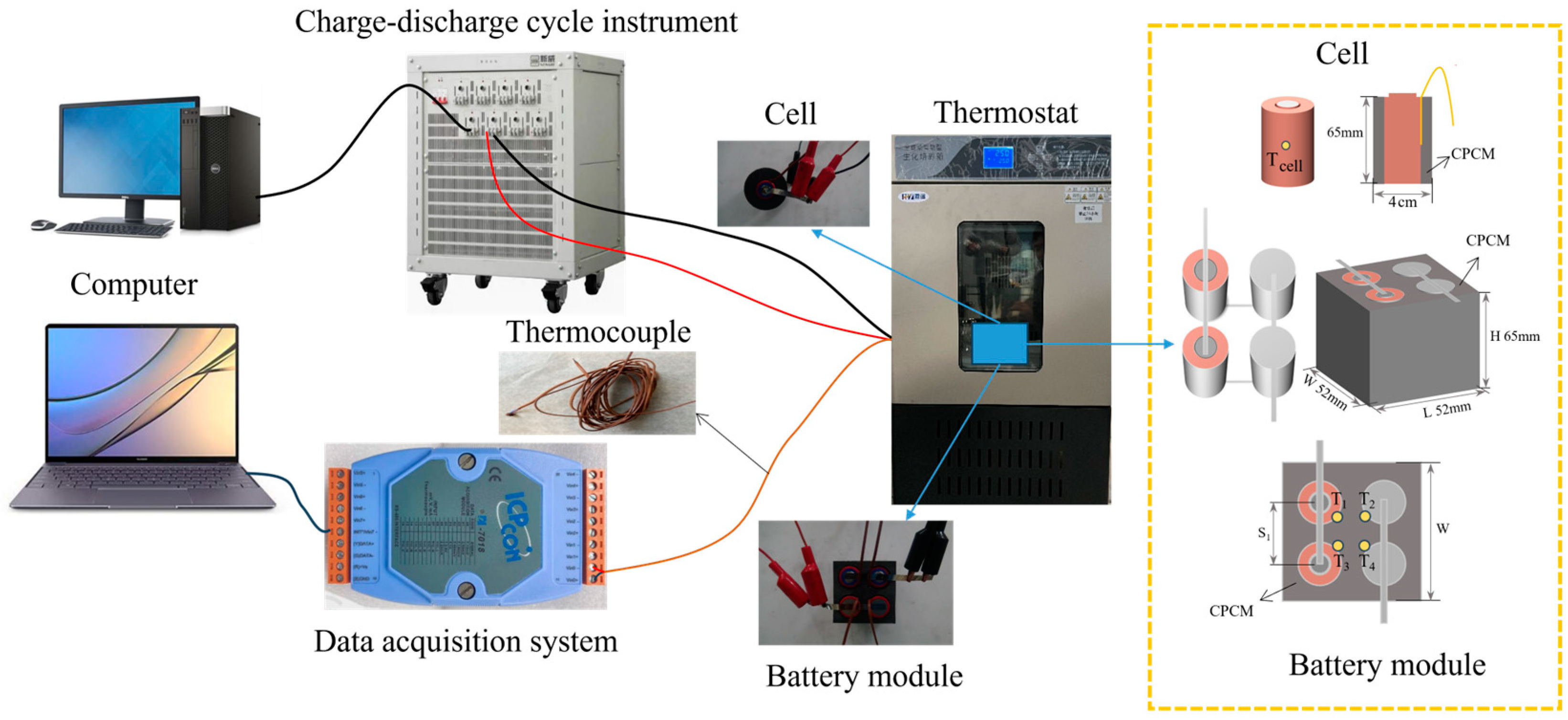
This study employed 18,650 cells manufactured by Sanyo Corporation (Tokushima, Japan). These batteries have a nominal capacity of 3.2 Ah, a rated voltage of 3.7 V, and are fully charged to 4.2 V. Before utilizing the new battery, it is essential to conduct an initial cycling process and allow it to remain idle for over 24 h to ensure battery stability. The quiescent period ensures battery stability and establishes a consistent baseline for subsequent testing [
51]. In this experiment, the thermal management performance of the prepared CPCM was studied in the cell and the battery module comprising four cells connected in a 2-series, 2-parallel configuration. CPCM and cells form a cuboid battery module with dimensions of 52 mm × 52 mm × 65 mm (L × W × H).
Figure 2 illustrates the battery connection method, the arrangement of thermocouples, and the specific settings used for the charge and discharge experiments of the battery module.
Table 2 shows the detailed information of instruments applied in this work.
In a thermostat with a temperature of 25 °C, the batteries underwent an initial discharge at rates of 1C, 2C, and 3C, respectively. Subsequently, the batteries were allowed to rest for 5 min after discharge, followed by recharging at a rate of 1C until they reached full charge. “C” is a relative unit that represents a multiple of the battery’s capacity and is used to describe the rate of charging and discharging of the battery. Specific working conditions are shown in
Table 3.
The battery’s surface temperature was measured during the battery cycling process using thermocouples. Thermocouple placement in the middle of the cell surface provided a more representative temperature reading that could better reflect the uniformity of the temperature inside the cell and be less affected by the external ambient temperature. Similar experiments in previous studies would be set up with the thermocouple position in the middle of the cell surface [
52,
53]. Consequently, the thermocouple in the individual cell was positioned centrally on the battery surface, whereas the thermocouples in the battery modules were symmetrically fixed to the battery surface. Temperature data were collected and uploaded to the computer through the temperature data acquisition unit and 7018 temperature acquisition modules. Temperature changes on the surface of individual cells and battery modules with CPCM were measured. Calculations were made from the data to determine the average and maximum temperature difference for each battery module.
3. Results and Discussion
3.1. Characterization of the Properties of CPCM
The SEM images captured in
Figure 3 showcase the micrographs of CPCMs with EG and different CPCMs (PCM1 to PCM5), offering visual evidence of their composition and surface properties. EG possesses numerous irregular and distinctive worm-like microporous structures that offer specific attachment points for PA and BC. Collectively, these structures interconnect to create an extended thermal conductivity network.
Figure 3c demonstrates the successful adsorption of PA into the microporous structure of EG, resulting in a relatively smooth and flat surface of the PA-EG mixture.
Figure 3d–h show a rougher surface of the material, which indicates the successful embedding of BC into the pores of EG, and their uniform dispersion and intertwined features in the mixture can be observed. In EG to form a well-developed ultrafine network structure. This interwoven structure enhances thermal conductivity channels within the micropores of EG.
Figure 4 displays the test results for the CPCM’s thermal conductivity coefficient. The efficiency of heat absorption and release in PCM is significantly affected by the thermal conductivity coefficient, both high and low. To investigate the variability in thermal conductivity, different material proportions were added, and their thermal conductivity coefficients were measured. The results indicated that the thermal conductivity coefficients of PA, PCM1, PCM2, PCM3, PCM4, and PCM5 were 0.2, 1.24, 1.27, 1.31, 1.34, and 1.39 W·m
−1·K
−1, respectively. The modest improvement in thermal conductivity of the composites containing 5 wt% EG content can be ascribed to the even dispersion of EG particles. These particles become enveloped by an excess of PA, impeding their effective contact and resulting in an incomplete network structure. BC possesses an ultra-fine network structure, which, upon incorporation, establishes a novel heat transfer matrix/conductivity network within the pores of EG. This network interconnects with EG and acts as a “thermal bridge” through the PA, thus augmenting the heat transfer pathway within the CPCM. The study revealed that the increase in thermal conductivity is mainly attributed to the EG content, followed by BC. A dense and uniform microstructure can effectively enhance the material’s strength and thermal conductivity [
28]. The BC exhibits a ribbon-like shape, where the fibers intersect to create a delicate network structure. The addition of BC can establish improved thermal conduction pathways, thereby enhancing the thermal conduction capacity of CPCM.
Figure 5a,b display the leakage rate and shape of CPCM at 80 °C under different times. In
Figure 5a, CPCM retains its initial shape even after 6 h, demonstrating remarkable structural stability.
Figure 5b reveals that PCM1 exhibits the highest leakage rate, followed by PCM2, PCM3, and PCM4, while PCM5 demonstrates the lowest leakage rate. During the heating process, the PA in the CPCM melts, resulting in the closure of the micropores in the EG. This indicates that a 5 wt% EG concentration alone is insufficient for complete PA absorption; however, the BC powder exhibits a certain level of PA adsorption capacity. Furthermore, samples with higher BC content demonstrate decreased PA leakage. The leakage rate of PA-BC-EG exhibits an inverse correlation with the BC content. The intertwining of BC within EG results in the formation of a highly porous structure with excellent compatibility, facilitating enhanced adsorption of PA and reducing the leakage rate of CPCM.
XRD testing was conducted on the raw materials (PA, EG, and BC powder) as well as the composite materials (PCM1 to PCM5) to analyze their respective peaks and diffraction angles.
Figure 6 displays the outcomes of the test. The XRD spectrum shows that PA exhibits diffraction peaks at 21.48° and 23.77°, while EG and BC display diffraction peaks at 26° and 29.04°, respectively. Although the diffraction intensities of the peaks vary, the XRD curves of PCM1 to PCM5 exhibit identical peaks at the same positions as PA, BC, and EG. This confirms that there were no newly emerged peaks during the synthesis process of PCM1 to PCM5. This suggests that no chemical reactions took place in CPCM, and no new substances were formed. PA-EG-BC are merely combined through physical interactions.
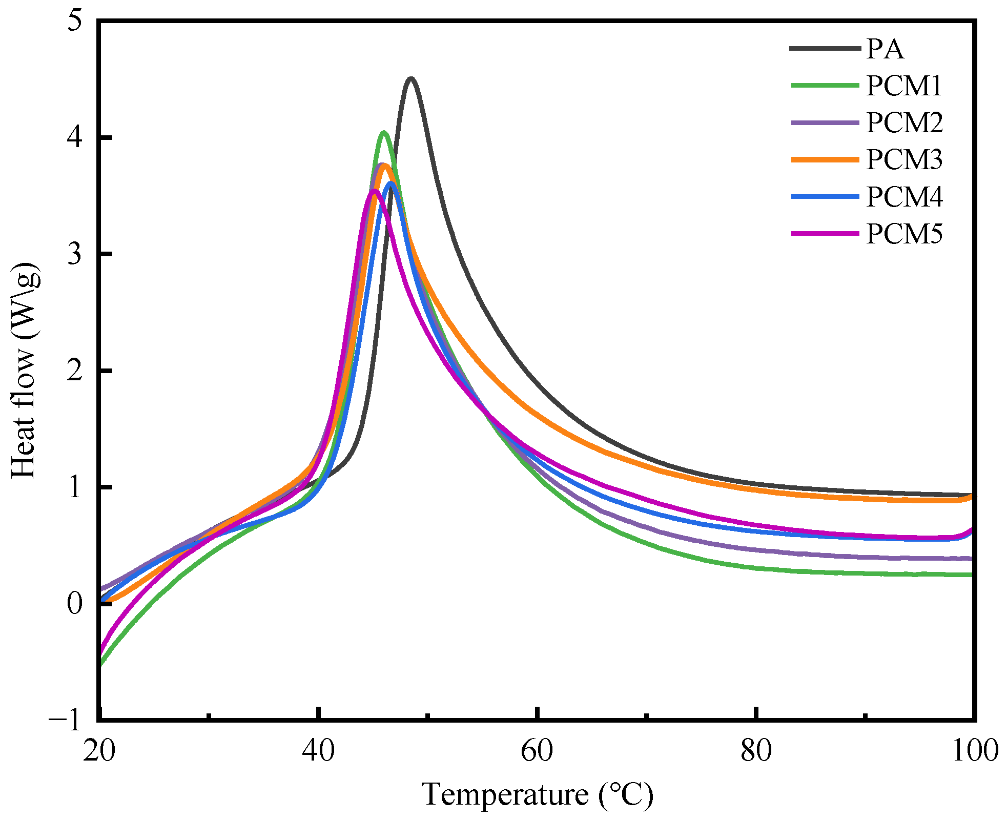
The DSC curves of PA and composite materials (PCM1 to PCM5) are depicted in
Figure 7. The results demonstrated that the inclusion of thermally conductive fillers, EG and BC, led to a reduction in latent heat. PA has a maximal latent heat of 220 J/g. The latent heat of PCM1 to PCM5, when exposed to the same 5 wt% EG heat conducting filler load, decreases overall, from 204.02 J/g to 175.43 J/g. This suggests that the percentage of PA determines the latent heat capacity of CPCM. With an increase in BC, the melting point and peak temperature of CPCM slightly decrease, with the peak temperature reducing from a maximum of 47.3 °C to 45.3 °C. The incorporation of EG and BC can enhance the material’s heat-conducting properties, thereby accelerating heat transfer within the material. Consequently, the material undergoes continuous melting and release of latent heat at relatively low temperatures, leading to a decrease in the initial melting point and peak temperature. The CPCM achieved in this study exhibits excellent thermal performance similar to the previous studies, as shown in
Table 4. The melting latent heat of the 1,6-hexanediol/nano titanium dioxide CPCM is slightly higher than that of PCM5, while the melting heat of other CPCMs is lower than that of PCM5. Additionally, the thermal conductivity of PCM5 is 6.71 times higher than that of the palmitic acid/ethyl cellulose CPCM.
Thermal stability is a crucial parameter for utilizing CPCM in BTMS, as the thermal decomposition temperature defines its operational temperature range. The thermogravimetric results for PA and PCM1 to PCM5 are presented in
Figure 8. As depicted, both PA and PCM1 undergo single-step decomposition, primarily attributed to the decomposition of PA. PCM3, PCM4, and PCM5 display a two-step decomposition mechanism. The initial step takes place between 130 °C and 180 °C, with weight loss attributed to BC decomposition, while the second step occurs between 200 °C and 300 °C, aligning with the degradation stage of pure PA. As BC content increases, the residue of CPCM also increases substantially, showing residue amounts of 10.18%, 9.22%, and 7.62% for PCM3, PCM4, and PCM5, respectively. This indicates the successful formation of a stable skeleton structure after BC effectively adsorbs into the pores of EG. The TG results demonstrate that CPCM exhibits thermal stability beyond its operational temperature (phase change temperature) of 130 °C, ensuring its suitability for practical applications.
3.2. Thermal Management Effect of CPCM
The temperature of LIBs increases during charge/discharge cycling, which is related to the internal resistance of the battery, the electrochemical reaction, and the external environment. When the heat dissipation of the battery is less than the heat generated, the battery temperature increases. Uneven heat generation leads to a highly heterogeneous temperature distribution across the surface of the batteries within the battery module. Exceeding a certain temperature threshold can result in capacity degradation and even TR. Experiments were conducted to assess the influence of varying BC contents in CPCM on the thermal management effectiveness of cell and battery modules. The cooling effect on LIBs in the NO-PCM and five different CPCMs was investigated at a charging rate of 1C, a discharging rate of 1C, 2C, and 3C, and an ambient temperature of approximately 25 °C.
3.2.1. Cell
This study employs five types of CPCM to measure surface temperature during battery charging and discharging processes, investigating the impact of a singular thermal filler on battery thermal management. A comparison of the surface temperature of CPCM batteries under various operating conditions leads to the conclusion that the CPCM utilized in this study exhibits a significant cooling effect.
Figure 9a–c depict the temperature curves of a single cell subjected to various operating conditions, including 1C charging and discharging at rates of 1C, 2C, and 3C. As indicated in the figures, during the discharge stage at all three rates, the battery temperature increases rapidly, attributed to the battery’s high internal resistance and significant heat generation. During the charging stage, the temperature gradually and gently decreases until the fully charged battery reaches approximately 25 °C. Comparing different discharge rates reveals that higher discharge rates result in increased temperature rise in the battery. The inability of the NO-PCM battery to rapidly transfer the heat produced by the cell results in heat accumulation within the cell. CPCM serves as a temperature buffer during absorbing heat when the cell temperature rises and releasing heat when it falls. When discharged at a rate of 1C, the cell employing PCM1 and PCM5 exhibited peak temperatures of 33.3 °C and 32.5 °C, respectively. A comparison of the temperature data at a discharge rate of 3C reveals a significant reduction in peak temperature for CPCM batteries. Furthermore, the cooling effect of CPCM remains consistent across various operating conditions. Consequently, it is inferred that a higher thermal conductivity of CPCM yields superior performance in practical applications, assuming similar latent heat parameters.
3.2.2. Battery Module
Figure 10a–c display the battery module’s temperature fluctuations at various discharge rates and the temperature uniformity between cells within the module at 25 °C (±0.5 °C) using different CPCM. The battery modules NO-PCM are included as control experiments. The results suggest that CPCM demonstrates consistent cooling behavior for both cell and battery modules. The overall temperature uniformity within the module aligns with the heat generation during charging and discharging. Notably, PCM5 demonstrates a more significant cooling effect and improved temperature uniformity between cells within the battery module. The battery module is discharged at rates of 1C, 2C, and 3C, resulting in peak temperatures of 39.7 °C, 59.3 °C, and 64.2 °C, respectively, for the NO-PCM module. By employing PCM5 battery modules, the maximum temperatures recorded at different discharge rates decrease to 37.2 °C, 42.1 °C, and 46.9 °C. The temperature reduction was substantial compared to natural convection cooling, with decreases of 17.8 °C and 17.3 °C at discharge rates of 2C and 3C, respectively. The temperature distribution within the battery module exhibits significant unevenness, with maximum temperature differences of 1.5 °C, 5.8 °C, and 9.5 °C. This unevenness results in heightened heat generation within the cell, and if the temperature difference is substantial, it may potentially trigger TR. In addition, the presence of temperature differences may lead to inconsistent thermal expansion within the battery and in different parts of the CPCM, which in turn causes stresses and strains that accelerate battery aging and damage. Ensuring temperature uniformity within the module is vital for minimizing long-term degradation of battery performance [
58,
59]. The utilization of CPCM demonstrates effective temperature control on the cell surface and achieves desirable uniformity of temperature within the battery module. The optimal operating temperature range for lithium batteries is 15 °C to 35 °C, with a recommended temperature difference between batteries of less than 5 °C [
60]. In the experiment without CPCM, the temperature differences at 2C and 3C exceeded the safety threshold of 5 °C. After the addition of CPCM, the temperature difference is controlled within 2.4 °C at 2C conditions and within 3.3 °C at 3C conditions. The main reason for the reduction in temperature difference between cells within the battery module and the LIB module is that, under high discharge rates, a portion of the heat is absorbed by the CPCM when the battery module’s temperature rises over the CPCM’s phase change temperature. It is worth noting that the maximum temperature on the surface of the battery after using CPCM still exceeds the optimal operating temperature range of LIBs, and the temperature of all samples in the battery thermal management still exceeds 35 °C when there are only four batteries in the battery module. This exceeds the optimal operating temperature range of LIBs. This situation, therefore, demonstrates the limitations of using CPCM in BTMS. One possible limitation is that the latent heat of the CPCM is not sufficient to effectively absorb and store the heat generated by the battery module. When the number of cells is high, or the cell workload is large, the heat absorption capacity of the CPCM may be limited, resulting in temperatures outside of the desired range. In addition, the phase change temperature range of the CPCM may also be a limiting factor. If the phase change temperature of the CPCM is not suitable for the operating temperature range of the battery system, it may not be able to provide sufficient heat absorption or release to maintain a stable temperature. Therefore, when using a CPCM in a BTMS, careful consideration needs to be given to the effects of the latent heat of the CPCM, the phase change temperature, and the number of batteries and workloads in the system to ensure that the CPCM can effectively manage the heat from the battery module to avoid temperatures that are outside of the safe range.
3.3. Discussion on CPCM Practical Applications
The utilization of CPCM in this work resulted in a more consistent temperature distribution throughout the battery module, ensuring uniform temperature maintenance. Under high discharge rates, the cell surface temperature increases considerably, leading to a highly uneven temperature distribution within the battery module. This is due to the relatively low heat generation of the cell during 1C discharge, which results in minimal temperature non-uniformity, with a maximum temperature difference of 1.5 °C. The utilization of CPCM battery modules helped to control temperature differences to approximately 1 °C. At discharge rates of 2C and 3C, the battery module’s temperature fluctuates dramatically. This is because, under high discharge rates, the cell generates a significant amount of heat that is constrained by the thermal conductivity of the CPCM itself, leading to delayed transfer to the external environment.
The phase transition temperature of the CPCM in this work is approximately 45 °C. During the 2C and 3C cycles, the cell temperature of the battery module surpassed the optimal operational temperature of the cell. If the battery module undergoes expansion, the heat absorption or release capacity of the CPCM might be insufficient for the thermal management system’s demands, necessitating a higher phase transition temperature. Additionally, fluctuations in ambient temperature must be taken into account. If the ambient temperature fluctuates significantly, it may change the phase change characteristics of the CPCM, which may lead to unstable temperature regulation. As the CPCM in this study undergoes 100 or 200 cycles within battery thermal management, the phase transition temperature of approximately 45 °C may encounter certain limitations and obstacles. The CPCM exhibits a minor leakage rate, and its phase transition dynamics can be influenced by the cycle count during the battery’s charge and discharge processes. Repetitive phase transition could result in the deterioration of the CPCM’s efficacy, manifesting as alterations in phase transition temperature and a decline in its heat absorption/release capabilities. As the number of cycles increases, BC may spill out of the EG, causing structural changes in the CPCM, resulting in degradation of performance, which can affect its stability. As a result, periodic replacement or maintenance of the CPCM substance may be required, which poses a challenge for extended cycle durations.
CPCM absorbs excess heat during battery operation to avoid overheating the battery and is able to conduct heat more quickly due to its high thermal conductivity. This is critical for battery thermal management, especially in high-rate charge/discharge applications. High thermal conductivity helps to quickly transfer the heat generated in the battery to the thermal cooling system, preventing overheating and improving the thermal efficiency of the system. Reduced leakage rates mean that CPCM is more stable over long periods. The application of CPCM improves temperature uniformity within the battery module and reduces temperature gradients, preventing localized over- or under-temperatures. This helps to improve the stability and safety of the battery. As an energy storage material, CPCM is characterized by reusability and cyclic stability, which meets the requirements of sustainable development. By applying CPCM in electric vehicles and renewable energy storage systems, the sustainability of the system can be improved, and energy consumption and environmental impact can be reduced. In this experiment, the raw materials of CPCM, PA, and EG are relatively cheap and widely available, and the supply is relatively stable, CPCM is a physical mixing process, which means that the physical and chemical properties of CPCM can be accurately controlled in the process of large-scale production, and the CPCM has a good thermal conductivity and efficient thermal management capability and can be designed in different shapes according to different battery sizes, which is practical. CPCM has good thermal conductivity and efficient thermal management capability and can be designed in different shapes according to different battery sizes, which is practical.
BC is a renewable resource, usually synthesized through bacterial fermentation. It has good biocompatibility and degradability, and these properties allow it to be used as a material for the production of biodegradable plastics, which can help to promote resource sustainability in the face of the current serious environmental challenges of global plastic pollution. EG can be physically recycled and reused.
On the other hand, there may be compatibility issues with applying CPCM to existing battery designs. Battery designs are often carefully optimized and validated systems, including aspects such as cell structure, dimensions, and thermal management systems. Introducing CPCM into them may require modification or re-evaluation of the battery design to ensure the adaptability and effectiveness of CPCM. This may involve aspects such as adjustments to the physical structure, optimization of heat transfer paths, and coordination with other components. In addition, the battery sector has very stringent safety and regulatory requirements. How to verify that the use of CPCM does not increase the safety risk of the battery system is an issue that needs to be considered. In addition, it is worth noting that the production of BC cannot be commercialized on a large scale, and the development of lower-cost, larger-scale production of bacterial cellulose needs to be further explored.
In summary, CPCM can be used for thermal management applications in the field of LIBs. It can be used as a matrix for phase change energy storage materials for absorbing and releasing thermal energy for temperature regulation. In addition, this material has the potential for thermal management applications in areas such as construction, textiles, and electronic devices to improve energy efficiency and comfort. More work should be conducted in the future to construct a fine structural network model to study the uniformity of temperature distribution during the battery module charge/discharge cycle.
4. Conclusions
In summary, we have successfully synthesized an innovative CPCM using PA as the phase transition core, EG as the supporting framework, and BC as the ultra-fine network structure. The addition of EG and BC significantly enhanced the thermal conductivity of the CPCM, reaching 1.39 W·m−1·K−1, which not only improved the heat transfer but also stabilized the material during phase transitions. The incorporation of BC’s physical crosslinking network further contributed to the material’s shape stability, enhanced latent heat capacity, and improved thermal cycling reliability.
Through experimental analysis, we found that the CPCM significantly improved the thermal management performance of BTMS. Under various operating conditions, the CPCM maintained the battery module’s maximum temperature below 47 °C and reduced the maximum temperature difference to within 4 °C. Moreover, when compared to a system without phase change material at a 3C discharge rate, the CPCM reduced the maximum cell temperature, maximum module temperature, and maximum temperature difference by 32.38%, 26.92%, and 34.94%, respectively.
These findings contribute to our understanding of CPCM effects on temperature differentials within battery modules and offer insights for the development of BTMS. Future research could focus on constructing a refined structural network model to investigate temperature distribution uniformity during battery module charge/discharge cycles.


