Article

Study of the Effects of Er Doping on the Physical Properties of CdSe Thin Films

by
Yuliana de Jesús Acosta-Silva
1,*,
Luis A. Godínez
2,
Manuel Toledano-Ayala
1,
Rosendo Lozada-Morales
3,
Orlando Zelaya-Angel
1 and
Arturo Méndez-López
1,*
1
División de Investigación y Posgrado, Facultad de Ingeniería, Universidad Autónoma de Querétaro, Centro Universitario, Queretaro 76010, Mexico
2
Centro de Investigación en Química para la Economía Circular, CIQEC, Facultad de Química, Universidad Autónoma de Querétaro, Centro Universitario, Queretaro 76010, Mexico
3
Facultad de Ciencias Físico-Matemáticas, Benemérita Universidad Autónoma de Puebla, Puebla 72570, Mexico
*
Authors to whom correspondence should be addressed.
Magnetochemistry 2023, 9(4), 107; https://doi.org/10.3390/magnetochemistry9040107
Submission received: 22 December 2022 / Revised: 7 April 2023 / Accepted: 11 April 2023 / Published: 14 April 2023
(This article belongs to the Special Issue Magnetic Materials, Thin Films and Nanostructures)

Abstract

:
Erbium-doped cadmium selenide thin films grown on 7059 Corning glass by means of a chemical bath at 80 °C were prepared. Doping was performed by adding an aqueous Er(NO3)33·H2O dilution to the CdSe growth solution. The volume of Er doping solution was varied to obtain different Er concentration (x at%). Thus, in the Cd1−xErxSe samples, the x values obtained were in the 0.0–7.8 at% interval. The set of the CdSe:Er thin films synthesized in the hexagonal wurtzite (WZ) crystalline phase are characterized by lattice parameters (a and c) that increase until x = 2.4% and that subsequently decrease as the concentration of x increases. Therefore, in the primitive unit cell volume (UC), the same effect was observed. Physical parameters such as nanocrystal size, direct band gap (Eg), and optical longitudinal vibrational phonon on the other hand, shift in an opposite way to that of UC as a function of x. All the samples exhibit photoluminescence (PL) emission which consists of a single broad band in the 1.3 ≤ hν ≤ 2.5 eV range (954 ≥ λ ≥ 496 nm), where the maximum of the PL-band shift depends on x in the same way as the former parameters. The PL band intensity shows a singular behavior since it increases as x augments but exhibits a strong decreasing trend in the intermediate region of the x range. Dark d.c. conductivity experiences a high increase with the lower x value, however, it gradually decreases as x increases, which suggests that the Er3+ ions are not only located in Cd2+ sites, but also in interstitial sites and at the surface. Different physical properties are correlated among them and discussed considering information from similar reports in the literature.

1. Introduction

The wide implementation of thin films in various applications, prepared with compound semiconductors of the IIA-VIB group is due to their excellent characteristics; therefore, these compounds have attracted the attention of several research groups around the world [1,2]. Due to the compatibility in the synthesis of stoichiometric and non-stoichiometric compounds, the cadmoselite or cadmium selenide (CdSe) is a particularly attractive metal selenide from the II–VI group [3]. Its high absorption coefficient, appropriate band gap of 1.74 eV (which is close to the ideal band gap desired for an appropriate absorber layer), high electron affinity, elevated photosensitivity, and n-type conductivity, makes it one of the prominent competitors among Cd-based chalcogenides of the II–VI group [4,5,6]. Cadmium selenide is therefore an interesting semiconductor material that has been used as a model substrate to design, prepare and pursue novel applications such as semiconductor nanostructures [7], luminescent nanocrystals [8], phase transformations [9], vibrational modes [10] and colloidal luminescent monolayers [11], among others. In most cases, CdSe exhibits n-type conductivity, which is dependent on its growing dynamics and on the development of vacancies. The n-type conductivity of CdSe films is caused by the Se vacancies, but the p-type conductivity may be caused by an Se surplus [6]. The CdSe material primarily exhibits cubic and hexagonal phases of crystallization and a combination of the cubic and hexagonal phases could arise during crystallization [6,12]. Several reports on the synthesis, properties and potential applications of CdSe have been published [13,14,15] and in the specific field of synthesis, new techniques to prepare chemically grown nanostructured CdSe films have been discovered. Among these, thermolysis of Cd and Se reagents [16], green methods [17], reverse micelle assisted hydrothermal [18] and rapid microwave synthesis [19], stand out as approaches to synthesize materials that can be used to prepare composite structures such as polymerized CdSe nanocrystals (NCs) [20], organic-inorganic hybrid CdSe NCs [21], CdSe-polymer fibers [22] and biocompatible CdSe-ZnS NCs [23]. These novel CdSe arrangements have been explored for applications in semiconductor nanostructure technology [24,25], food science [26] biologic images [27], agriculture [28] and DNA studies [29], among others.
The intrinsic CdSe nanobelts (NBs) exhibits an extremely high resistivity of 1 × 10¹³ Ω cm and thus leads to its low conductivity [30]. In order to further expand its usage, it is necessary to adjust the carrier concentration and then mediate its bandgap. Several researchers intentionally introduced defects by doping and thus changed carrier concentrations to enhance its electro-optical properties [31,32,33,34,35,36]. Up to now, doping has resulted in optical, electronic and transport control as well as in spintronic properties of the semiconductor materials [37]. For example, Mg-doped CdSe can modulate its optical bandgap and makes possible light response in the whole visible range [38]. Sahu et al. doped CdSe nanocrystals with Ag impurities and investigated their optical and electrical properties. They observed that doping leads not only to dramatic changes but surprising complexity. The addition of just a few Ag atoms per nanocrystal causes a large enhancement in the fluorescence. While Ag was expected to be a substitutional acceptor, nonmonotonic trends in the fluorescence and Fermi level suggest that Ag changes from an interstitial (n-type) to a substitutional (p-type) impurity with increased doping [8].
In the case of rare earth (RE) element doping, interesting results have been obtained using CdSe as the semiconductor substrate. While CdSe:Y3+ for example, has been used for luminescence enhancement [39] and CdSe:Gd for potential optical and MR imaging [40], CdSeEu has been found to be an efficient photocatalytic material [41]. The morphological, structural, optical and other properties of a host lattice can be improved by gradual and systematic addition of various dopants [42,43]. On the other hand, erbium is another rare earth element used as impurity in optical amplifiers because of its high capacity to supply both high gain and high at-saturation output. The Er3+ ion is also an active lasing element. Therefore, Er3+ has become one of the most interesting topics of research due to 4I9/24I15/2 and 4I11/24I13/2 transitions [44], and these characteristic properties open up a new line of research for these materials due to the intra Er3+ 4f shell transition from its first excited state (4I3/2) to the ground state (4I5/2) [45]. In this context, the aim of the present work is to study some of the morphological, structural and optical properties of Er3+-doped CdSe thin films in order to obtain crystalline films. CdSe thin films were grown using the chemical bath (CB) method. In this way, Er3+ ions were efficiently incorporated into the semiconductor CdSe hexagonal wurtzite (WZ) crystalline phase with no important distortion of the lattice structure. Er3+ ions in the CdSe hexagonal wurtzite lattice are expected to occupy Cd2+ sites to produce an n-type CdSe doped substrate and in this work, the Er3+ doping values fall within the 0.0–7.8 at% interval. The WZ unit cell parameters, crystal size, vibrational modes, energy band gap, luminescence spectra and dark conductivity experience changes depending, as expected, on the Er concentration. The variation in these parameters and properties are discussed on the basis of the correlation of the experimental data obtained and of the information from similar works in the literature.

2. Experimental

Nanocrystalline CdSe:Er thin films were deposited on Corning 7059 glass substrates at 80 ± 1 °C. The glass substrates were cleaned by immersion in water for a couple of hours, and successive ultrasonic treatment using trichloroethylene, acetone, and deionized distilled water. Finally, the glass substrates were dried under a stream of pure N2. The solutions employed in the growth of the CdSe:Er layers were: CdCl2 0.02 M, KOH 0.05 M, NH4NO3 1.5 M, CSe(NH2)2 0.02 M, and Er(NO3)3·3H2O 0.5 M. The total volume of the growing solution, VT = 100 mL, consists of the volume solution VCdSe for CdSe plus the volume solution, VEr, containing the doping Er chemical: VCdSe + VEr = VT = 100 mL. VR = (VEr/VT)100% on the other hand, corresponds to the relative volume, and different VR values were chosen within the 1.0% to 25% interval in order to obtain eight different doping levels. The growing time was one hour for all the film depositions.
The average thickness (τ) of the films correspond to 200 ± 10 nm as measured with a KLA TENCO P-15 profilometer. Optical transmittance spectra were obtained using a UNICAM 8700 spectrophotometer. X-ray diffraction (XRD) patterns were measured using a Rigaku D/max-2100 diffractometer (CuKα radiation, λ = 0.15406 nm). High resolution (HR-TEM) images were registered in a Transmission Electron Microscope (TEM) Jeol 2010 working at 200 KeV, in which thin layers of the CdSe films were detached from the substrate and supported on TEM-grids. The selected area for electron diffraction (SAED) was performed at the camera length, L¼-20 cm. Measurements of the atomic concentration of elements were obtained by means of energy dispersion spectroscopy (EDS) utilizing a Voyager II X-ray quantitative microanalysis in an1100/1110 EDX system from Noran Instruments. Photoluminescence (PL) measurements were obtained using a 0.5 m Jovin-Ivon double spectrograph, employing as the excitation source the 441.6 nm (2.808 eV) line of an Omnichrome 2056 He-Cd laser with 35 mW of power. Raman spectra were obtained by means of a microRaman spectrometer (Jobin Yvon, model Labram) using the 632.8 nm laser line from a He–Ne laser. Finally, dark electrical conductivity measurements were obtained in vacuum using the two points method and sign of carriers (n) by thermoelectric power. The essential drawback of the usual two-point method arises from the approximation of the intrinsic drain voltage by the external applied drain bias. This means that high series resistances can induce significant errors in the lifetime evaluation [46]. All the characterization measurements were carried out at room temperature (RT).

3. Results and Discussion

The CdSe:Er thin films prepared as described in the experimental section, appear bright and smooth to the naked eye, as can be seen from inspection of insets (i) and (ii) of Figure 1, which correspond to a doped (VR = 15%) and undoped samples, respectively. Figure 1 also exhibits the Er concentration measured by means of EDS, where each data point is an average value of ten measurements. As it can be observed in Figure 1, the EDS data (in at%) vs. VR plot, roughly follows a linear relationship. In the Cd1-xErxSe doped samples, the Er concentration (x) varied within the 0 ≤ x ≤ 7.8 at% range.
Nanocrystallites corresponding to the Cd1−xErxSe WZ structure for x = 4.6 at% can be seen in the TEM image of Figure 1b. The crystalline [002] planes of the WZ phase can also be observed, and the (002) interplanar spacing (IS) was determined as 0.35 ± 0.01 nm, which can be associated to the standard IS value 0.3505 nm of the [002] planes in WZ-CdSe (JCPDS CAS No. 08-0459). The inset of Figure 1b exhibits the first diffraction rings of the WZ-CdSe structure as well as the SAED pattern of the sample where the nanocrystalline character of the film is confirmed.
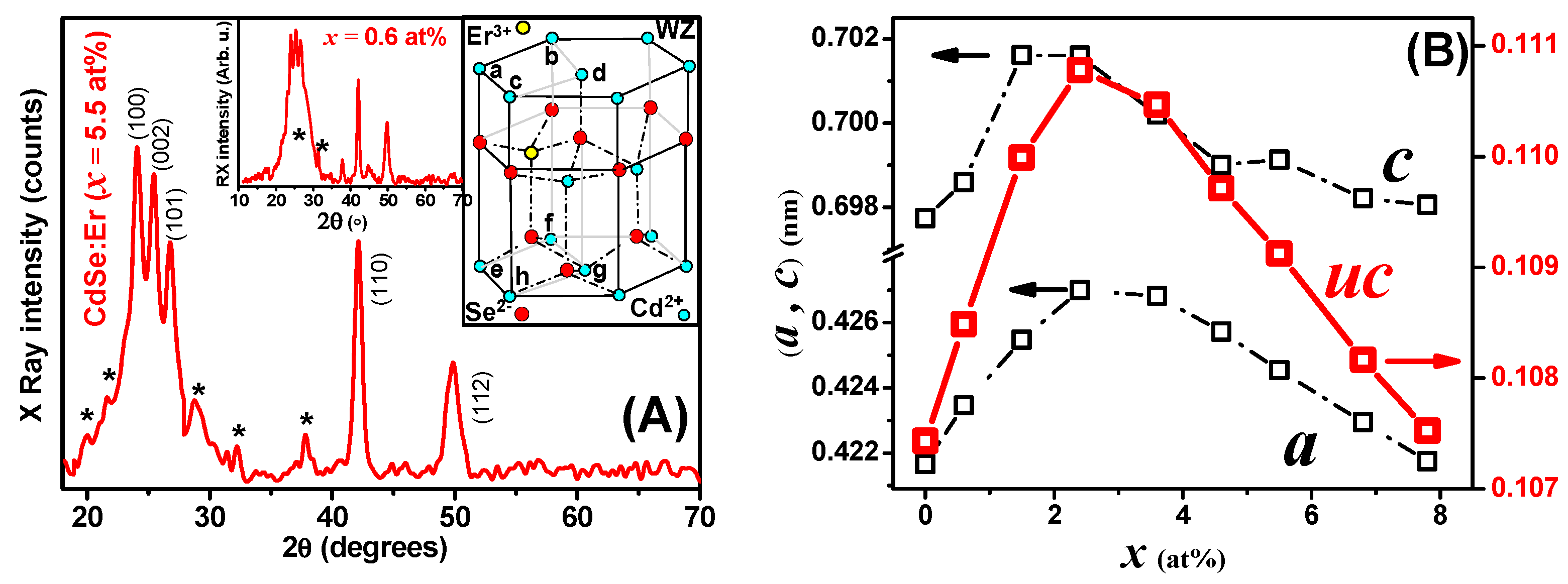
The hexagonal wurtzite structure of the CdSe samples in the crystalline phase obtained from the diffractograms of Figure 2A can be seen for two representative samples prepared with different doping levels (x = 5.5 and 0.6 at%). The asterisks in the diffractograms mark where the XRD reflections of Er2O3 should be present [47,48]; however, most of the peaks showed low intensity. Er2O3 has been reported to appear as another phase when CdSe nanocrystals are obtained from molecular precursors [49] and when GaNEr films are prepared using MOCVD [50]. As it was observed for the CB method and in the preparation of Si by different methods [51], in these synthesis techniques, oxygen is captured by Er3+ ions and the resulting Er2O3 oxide has for instance, been observed in Er doped ZnO NCs prepared using the sol-gel method [48].
The size of the CdSe:Er nanoparticles, observed by HRTEM coincides with the size of the crystallites observed by XRD [52]. In our case, the sizes of the crystallite (determined by XRD) using the Monshi–Scherrer equation [53] are comparable to the size of the particle sizes (observed by TEM). The observed nanoparticles are in the 8–15 nm size range (Figure 1b).
The XRD patterns revealed the CdSe and Er2O3 phases of the doped films and the right inset in Figure 2A shows the hexagonal WZ unit cell (UC) of CdSe, where the yellow circle represents the Er3+ ion in a Cd2+ site. The ab.gh parallelepiped represents the primitive UC with side “a” and height “c”, which correspond to the WZ lattice parameters. Figure 2B on the other hand, displays the a and c values of the UC as a function of the doping level, x. The corresponding data in the left axis reveals that for both parameters, there is an initial increasing tendency that reaches a maximum at around x~2.4 at%, and that is followed by a decreasing trend. As expected, the UC volume (right axis graph) follows a similar volcano shaped curve.
It is evident from the XRD pattern’s peaks that all films are polycrystalline, as well as from the spreading diffraction peak and the small shift in the (002) crystal plane. The integration of the Er3+ ion into the crystal structure of the CdSe film causes a shift in this peak that rises with Er3+. The (100) and (002) planes are positioned in the CdSe:Er film’s strongest reflection peaks. We believe that this behavior is related to Er3+ ion inclusion in the crystal lattice, which results in preferred orientation in certain crystal planes. The size of the ionic radii of Er3+ should be related with the lowest energy that favors preferential orientation in these crystal planes. The WZ phase is indicated by strong peaks on the CdSe:Er film, which indicates a better crystallinity.
The interesting relationship of the UC dimension data and the doping level of the semiconductor material can be interpreted considering the work of Hsu et al. [54] who reported a study of Er:GaSe. These authors suggested that the two acceptor levels were originated either from the substitution (SBSs) of one Er3+ for one pair of Ga2+ or interstitial (INSs) insertion of one Er3+ at interlayer sites. In the case of the material under study, it is possible to note that since the ionic radii are Cd2+: 0.95Å, Er3+: 0.89Å and Se2−: 2.025Å, we can assume that Er3+ ions occupy Cd2+ sites (similar cation-size). However, with a further increase in the Er dopant concentration, the dopant ions are probably incorporated at the interstitial sites (several papers have reported this change) [55,56,57,58,59]. Based on this, it is possible to suggest that according to the oxidation state of the Er+3 ion, this chemical species is incorporated into the crystal lattice of CdSe replacing a Cd2+ ion, thus providing an extra hole due to its deficiency in valence electrons (similar investigations have been reported for CdSe:Er films) [60].
Raman spectra of Er-doped CdSe nanocrystalline thin films in 150–700 cm−1 intervals can be seen in Figure 3a. An inspection of the corresponding data shows an increase in the phonon signals as x increases. These observations are similar to those reported by Portillo et al. [60]. A Raman spectrum of a representative CdSe:Er sample is exhibited in Figure 3a, where three overtones are observed in addition to the optical longitudinal A1LO mode at 205 cm−1 of the WZ CdSe structure. A Raman phonon mode for the monoclinic structure of Er2O3 at ~560 cm−1 can also be seen in the CdSe:Er spectrum of Figure 3b [61]. The 1LO phonon mode shows an asymmetric band, which reflects the presence of a surface mode [62]. In nanocrystals (NCs) this is mainly due to a high surface to volume ratio [63], surface-ions-bond contraction and quantum confinement [64]. Deconvolution of these signals separates the 1LO and the surface phonon modes (SPM), A and B, as shown in the inset of Figure 3c. The lower inset shows the 1LO mode in a magnified scale, where the frequency position as a function of x is clearly observed. This relationship resembles an inverse function of the CdSe UC versus x (see Figure 2B), in which lattice expansion implies phonon softening, and lattice contraction and phonon hardening. In the inset of Figure 3c on the other hand, it is possible to observe vibration displacements of the 1LO mode, which reflect bond-stretching vibrations [65]. As it was previously indicated, contraction or expansion of the CdSe lattice depends on the concentration of Er3+ impurities in the interstitial sites of the CdSe lattice. The B-data trend in Figure 3c indicates that the SPM shifts to lower frequencies when the doping increases; a fact that suggests that disorder augments almost monotonically as x increases [66,67].
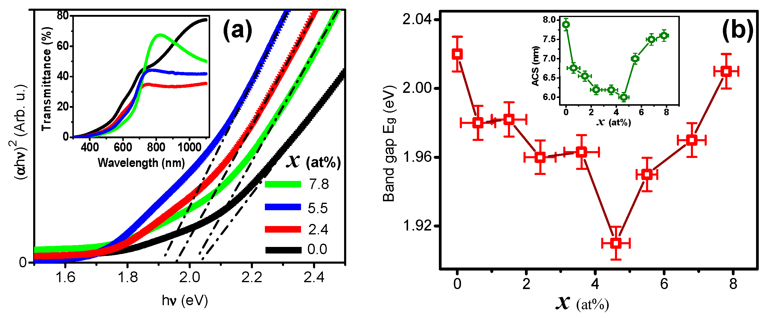
Figure 4a shows the Tauc method data used to calculate the CdSe direct energy band gap, Eg, in which the (αhν)2 versus hν plot was employed [68]. Here, α is the optical absorption coefficient, which was determined from the optical transmittance (To) (α = [Log{100/To}]/[τLoge]), hν is the photon energy; and only four samples are exhibited for clarity. The inset in this figure shows To spectra for the same four samples chosen for Eg calculation. Figure 4b displays Eg as function of x for the entire 0.0 ≤ x ≤ 7.8 at% range. The Eg dependence on x is in agreement with the UC vs. x plot, because, in general, if UC increases, Eg is reduced, and vice versa. However, this is not in agreement with the average crystal size (ACS) as function of x, since it can be readily seen that as ACS decreases, Eg also decreases. This is contrary to the quantum confinement effect since ACS should be within the strong quantum confinement regime (CdSe Bohr radius: 5.3 nm) [69]. This anomalous behavior can be explained considering the modifications in the lattice produced by the doping, which in turn can result in distortion, vacancies, interstitials, stress, expansion, contraction and non-stoichiometry effects, which can break the crystal symmetry and modify the physical properties of materials [70,71,72,73], particularly in the case of lanthanide doping [74]. The ACS dependence on x can be explained by surface tension increase that reduces crystal size when Er3+ bonds at the NC surface are formed [75,76]. It is also interesting to note that at x ≅ 4.6 at%, the effect of Er3+ on the NCs volume becomes important, and the ACS starts to increase. It can also be observed that the crystal size (Figure 4b green) behaves inversely to the unit cell size (Figure 2B red). We have obtained different values of Eg shown in Figure 4b red. Eg decreases with increasing erbium doping up to x = 4.6%, then it increases for x = 5.5 to 7.8%. The decrease in Eg may be due to the erbium electron localized states that create new states near the conduction band, leading to a reduction in the band gap of pure CdSe (similar observations were reported for ZnO) [77]. The variation in band gap depends also on particle size (Figure 4b green) and lattice parameters (Figure 2B). The decrease in particle size with increasing doping concentration leads to a rising of the band gap as the quantum refinement effect occurs [78]. The Bras’ effective mass model [79] can also explain our results. The energy gap (Eg) of the nanoparticles can be expressed, according to Bras’ effective mass model, as a function of particle size, as shown by the following expression:
E g = E b u l k + 2 π 2 2 R 2 1 m e + 1 m h 1.8 e 2 ε R
where E g is the measured band gap of the nanoparticles, E b u l k is the band gap of the bulk semiconductor, is the second Plank’s constant, R is the radius of the nanoparticle, m e is the effective mass of the electron, m h is the effective mass of the hole, e is the charge of electron, and ε is the electric permittivity of the material. The lattice parameters (a and c) and the unit cell volume (V) of nanoparticles can be calculated with the following equation:
1 d 2 = 4 3 h 2 + h k + k 2 a 2 + l 2 c 2
V = 3 2 a 2 c
where d is the interplanar distance and (h, k, l) are the Miller indices. The ratio a, c and the unit cell volume (V) for pure and Er-doped samples are shown in Figure 2B. It can be noticed that a, c and V are affected by erbium doping with an increase in their values up to x = 2.4% with respect to the pure sample. This behavior of a, c and V may be attributed to changes in the ionic size of Er3+ (0.89Å) substituting Cd2+ (0.95Å) in CdSe lattice. a, c and V decrease for x > 2.4% and in the end, they approach the values of pure CdSe. This cell contraction may be explained by the larger Er3+ ions leaving the CdSe lattice at high doping concentrations (x > 2.4%) to form the Er2O3 impurity [80,81]. The decrease in the lattice parameter c may also be attributed to the formation of defects in the CdSe lattice as a result of increasing the number of dopant (Er3+) ions, Dakhel et al. reported similar behavior when performing a different doping experiment [82].
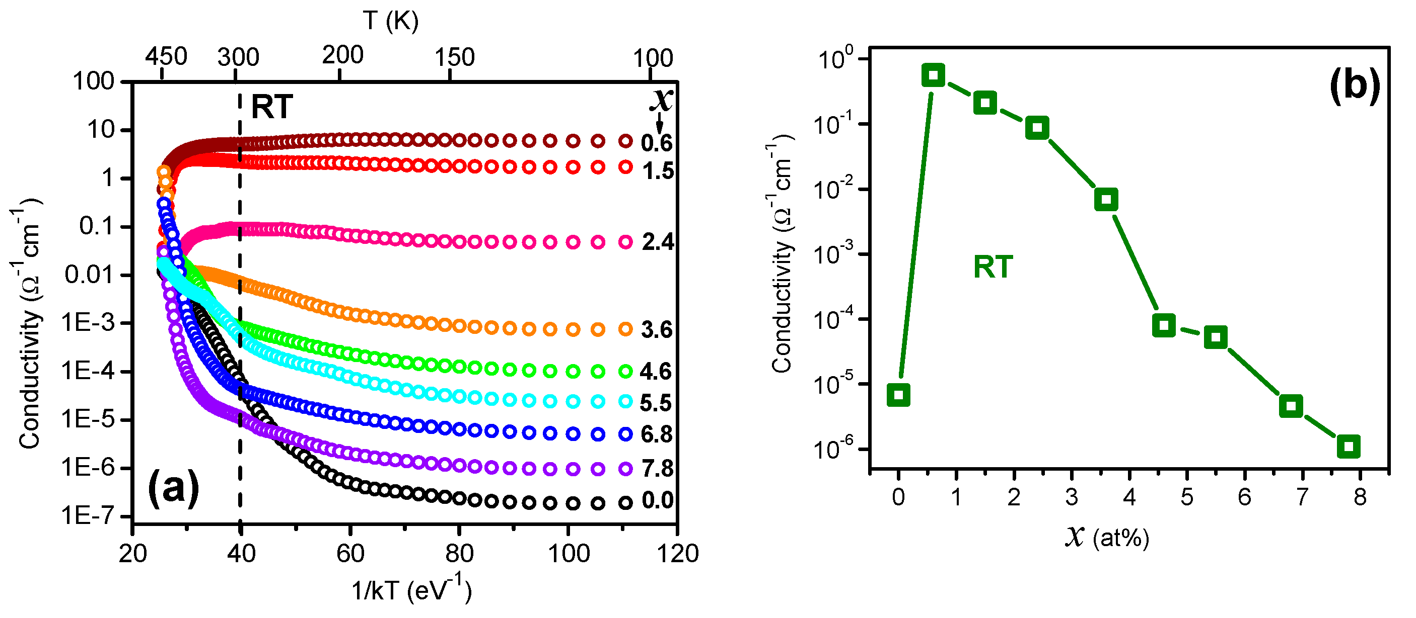
Figure 5a shows the dark d.c. conductivity (σ) dependences (presented on a semi-logarithmic scale) of Cd1-xErxSe, in the 10−7 to 101 Ω−1 cm−1 range, versus the inverse of the absolute temperature (T) times k (1/kT). Here, k corresponds to the Boltzmann constant. A metallic behavior of log (σ) vs. 1/kT is observed for x = 0.6, 1.5 and 2.4 at%, since σ remains essentially constant in the 300 ≥ T ≥ 35 K range (which is 35 ≤ 1/kT ≤ 110 (eV)−1), and decreases for T ≤ 35 K. For 3.6 ≤ x ≤ 7.8 at%, the behavior is that of a semiconductor with shallow donor levels, where the free carrier density decreases as x increases. The metallic dependence of log (σ) vs. T has been observed in ITO films grown by reactive plasma [83], and has been attributed to disorder in the lattice. Grenberg and coworkers [84] also reported a similar behavior at low temperatures for ZnO nanocrystals (NCs), which was obtained by changing the contact area and the center-to-center distance between NCs. A strong decrease in free carriers’ lifetime has been reported when the Er concentration increases, due to the formation of NCs [85,86].
In the case of the CdSe:Er NCs of this work, the incorporation of Er3+ produces an effective doping at low Er concentrations. When x rises, the formation of Er2O3 NCs (previously observed in XRD and Raman analysis) can produce barriers between the CdSe NCs which scatter the free carriers that, in turn, generate non-radiative transitions. σ at RT versus x is displayed in Figure 5b (see also dotted line in Figure 5a). The corresponding plot reveals that for low x values, σ increases almost five orders of magnitude. When Er concentration increases up to x = 7.8 at%, σ diminishes to values lower than those of the undoped sample. In this context, doping ZnO with Er3+ [87] and Ho3+ [88] shows that σ decreases when the impurity concentration increases. In the first case, the decrease is attributed to impurities scattering of free carriers and in the second case, to trapping at grain boundaries. Another effect of the Er3+ ion incorporation is the decrease in the crystallite size, which leads to higher grain boundary scattering, decreasing the mobility as well as the conductivity. As described by Callaway, when the grain size is decreased, the scattering rate of phonons become higher. Hence, it will lower the value of conductivity, which is favorable for various materials. However, as conductivity is reduced, the value of grain boundary scattering increases [89]. Morais et al., in their experiment of Er doped SnO2 thin films, indicate that by analogy, the overall effect of increasing the Er concentration is to decrease the film conductivity since an increase in the electric charge compensation, and decrease in the crystallite size, result in a decrease in the mobility since the grain boundary scattering is increased [90].
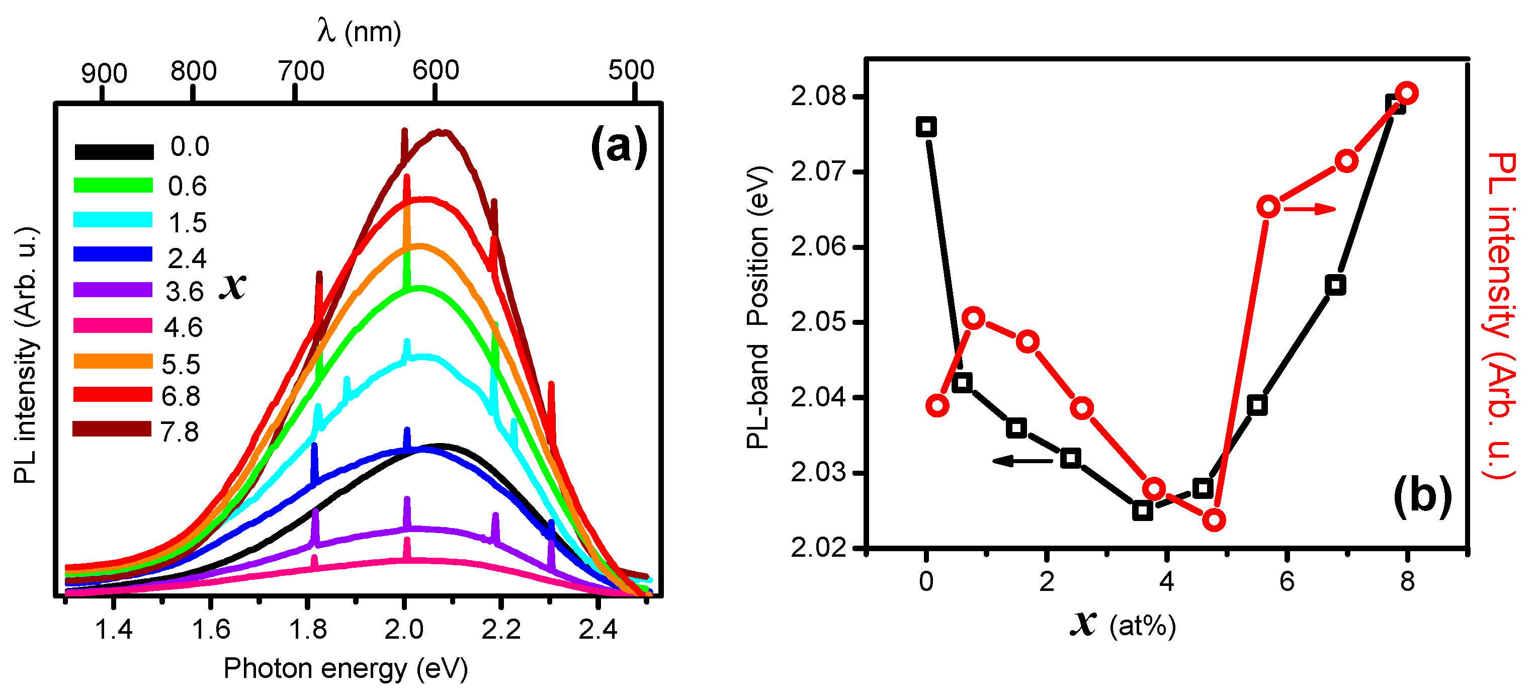
Photoluminescence (PL) measurements on the materials under study were carried out using as excitation source the 2.808 eV (441.6 nm) line of a He-Cd laser. Figure 6a displays the spectra for the Cd1-xErxSe films registered for all the films in the 0.0 ≤ x ≤ 7.8 at% range. All the samples exhibit a single PL broad band in the 1.4–2.5 eV interval (496–886 nm). Very narrow PL signals from Er3+ intra-atomic transitions [91] are observed in all spectra except for the undoped sample (x = 0). Several authors [92,93] report PL emission of rare earths doped and undoped CdSe NCs with a broad band centered in the 2.06–2.25 eV (550–600 nm) interval. The CdSe:Er samples of this work show the same PL band whose position depends on the NC size, doping type, and crystal defects. Other than the Er intra-atomic level transitions, no PL signals from Er2O3 oxide (see Figure 2A) could be observed. Figure 6b exhibits the PL band position (PLBP) as a function of the doping level x. Inspection of this data reveals that PLBP decreases in the 0.0 ≤ x ≤ 4 at% interval and increases for the remaining values. PLPB follows a tendency similar to that of the band gap (see Figure 4b), since PLBP is defined by an exciton emission [93]. The PLBP intensity versus x plot (right axis) does not show a gradual increase in the intensity. This result is not clear. It seems that PL intensity emission is reduced for smaller NPs and increases for larger sizes (see inset of inset of Figure 4b). As it was previously indicated, the crystalline quality of CdSe:Er films improves as x increases; a fact that suggests that defects on the NCs surface are responsible for the intensity abatement of PL spectra. The non-radiative transitions at the surface are increased when NC size decreases, along the 0.0 ≤ x ≤ 4.6 at% interval (see inset of Figure 4b). It is interesting note that a strong decrease in PL emissions has been observed in Er-doped GaAs due to the presence of ErAs precipitates in the GaAs matrix; giving place to Schottky barriers at the Er2O3-GaAs interface, which in turn form high n- and p-type depletion regions of high resistivity and very short carrier lifetimes [86]. Doping Er3+ in Hf-Al-silicate forms Er2O3 close the surface of planar waveguides, where the carriers’ lifetime decreases when the Er concentration increases [85]. In the case of the CdSe:Er samples under study, while lifetime and PL decreases for low Er concentrations, NC increases for higher x values (x~4.6 at%) where radiative transitions surpass non-radiative ones because the surface/volume ratio increases. As a consequence, the carriers’ lifetime also increases [94]. High density of Er2O3 NCs on the other hand, reduces σ and enhances PL signals.

4. Conclusions

In summary, Er incorporation in CdSe nanocrystals provokes drastic changes in the Cd1-xErxSe lattice structure, depending on the level of Er doping. For low x values, Er3+ ions are sequentially incorporated as follows: (i) replacement of Cd2+ ions, (ii) to interstitial sites, and (iii) to NCs surface. In the first (i) case, the unit cell volume tends to increase, and in the (ii) and (iii) cases, it tends to decrease. Er3+ in Cd2+ sites induce crystalline quality of CdSe as suggested from XRD and Raman measurements, thus Er3+ reduces the structural disorder but increases the chemical one. When the lattice expands, the 1LO phonon softens, and as expected, hardens if the lattice contracts. The surface mode softens continuously when x increases, which indicates that chemical disorder increases. The CdSe energy band gap decreases when UC increases and increases in the opposite case, which is a property of all semiconductors. Er2O3 NCs grow as a secondary phase, which forms barriers at the oxide-semiconductor interface, which gradually reduces the carriers transfer through the interface when x increases and, consequently, the film dark conductivity decreases. On the other hand, the Er2O3-CdSe band gap coupling enhances the photoluminescence, via conversion in the oxide, of CdSe. The findings of this work can be useful for the design of CdSe-based devices.

Author Contributions

Y.d.J.A.-S.: experimental, investigation, methodology, formal analysis; L.A.G.: formal analysis, resources; M.T.-A.: investigation, formal analysis; R.L.-M.: resources, validation; O.Z.-A.: Validation, Writing; A.M.-L.: Validation, visualization, Writing—Review & Editing. All authors have read and agreed to the published version of the manuscript.

Funding

This research received no external funding.

Institutional Review Board Statement

Not applicable.

Informed Consent Statement

Not applicable.

Data Availability Statement

The datasets used and/or analyzed during the current study are available from the corresponding author on reasonable request.

Conflicts of Interest

The authors declare no conflict of interest.

References

  1. Babu, N.S.; Khadar, M.A. Electrical properties of grain size tuned CdSe nanocrystal films for practical applications. Sol. Energy Mater. Sol. Cells 2018, 178, 106–114. [Google Scholar] [CrossRef]
  2. Hassen, M.; Riahi, R.; Laatar, F.; Ezzaouia, H. Optical and surface properties of CdSe thin films prepared by sol-gel spin coating method. Surf. Interfaces 2019, 18, 100408. [Google Scholar] [CrossRef]
  3. Ghobadi, N.; Sohrabi, P.; Hatami, H.R. Correlation between the photocatalytic activity of CdSe nanostructured thin films with optical band gap and Urbach energy. Chem. Phys. 2020, 538, 110911. [Google Scholar] [CrossRef]
  4. Dai, G.; Chen, Y.; Wan, Q.; Zhang, Q.; Pan, A.; Zou, B. Fabrication and optical waveguide of Sn-catalyzed CdSe microstructures. Solid State Commun. 2013, 167, 31–35. [Google Scholar] [CrossRef]
  5. Shyju, T.; Anandhi, S.; Indirajith, R.; Gopalakrishnan, R. Solvothermal synthesis, deposition and characterization of cadmium selenide (CdSe) thin films by thermal evaporation technique. J. Cryst. Growth 2011, 337, 38–45. [Google Scholar] [CrossRef]
  6. Bayramoglu, H.; Peksoz, A. Electronic energy levels and electrochemical properties of co-electrodeposited CdSe thin films. Mater. Sci. Semicond. Process. 2019, 90, 13–19. [Google Scholar] [CrossRef]
  7. Smith, A.M.; Nie, S. Semiconductor Nanocrystals: Structure, Properties, and Band Gap Engineering. Acc. Chem. Res. 2010, 43, 190–200. [Google Scholar] [CrossRef] [Green Version]
  8. Sahu, A.; Kang, M.S.; Kompch, A.; Notthoff, C.; Wills, A.W.; Deng, D.; Winterer, M.; Frisbie, C.D.; Norris, D.J. Electronic Impurity Doping in CdSe Nanocrystals. Nano Lett. 2012, 12, 2587–2594. [Google Scholar] [CrossRef] [Green Version]
  9. Tolbert, S.H.; Alivisatos, A.P. Size Dependence of a First Order Solid-Solid Phase Transition: The Wurtzite to Rock Salt Transformation in CdSe Nanocrystals. Science 1994, 265, 373–376. [Google Scholar] [CrossRef]
  10. Trallero-Giner, C.; Debernardi, A.; Cardona, M.; Proupin, E.M.; Ekimov, A.I. Optical vibrons in CdSe dots and dispersion relation of the bulk material. Phys. Rev. B 1998, 57, 4664–4669. [Google Scholar] [CrossRef] [Green Version]
  11. Delikanli, S.; Yu, G.; Yeltik, A.; Bose, S.; Erdem, T.; Yu, J.; Erdem, O.; Sharma, M.; Sharma, V.; Quliyeva, U.; et al. Ultrathin Highly Luminescent Two-Monolayer Colloidal CdSe Nanoplatelets. Adv. Funct. Mater. 2019, 29, 1901028. [Google Scholar] [CrossRef]
  12. Alasvand, A.; Kafashan, H. Comprehensive physical studies on nanostructured Zn-doped CdSe thin films. J. Alloys Compd. 2019, 789, 108–118. [Google Scholar] [CrossRef]
  13. Garg, N. A Brief Study on Characteristics, Properties, and Applications of CdSe. Proc. ICEMIT 2017, 2, 43–60. [Google Scholar]
  14. Yu, J.; Chen, R. Optical properties and applications of two-dimensional CdSe nanoplatelets. Infomat 2020, 2, 905–927. [Google Scholar] [CrossRef] [Green Version]
  15. Zhao, L.; Hu, L.; Fang, X. Growth and Device Application of CdSe Nanostructures. Adv. Funct. Mater. 2012, 22, 1551–1566. [Google Scholar] [CrossRef]
  16. Trindade, T.; O’Brien, P.; Zhang, X.-M. Synthesis of CdS and CdSe Nanocrystallites Using a Novel Single-Molecule Precursors Approach. Chem. Mater. 1997, 9, 523–530. [Google Scholar] [CrossRef] [Green Version]
  17. Ahmed, M.; Guleria, A.; Rath, M.C.; Singh, A.K.; Adhikari, S.; Sarkar, S.K. Facile and green synthesis of CdSe quantum dots in protein matrix: Tuning of morphology and optical properties. J. Nanosci. Nanotechnol. 2014, 14, 5730–5742. [Google Scholar] [CrossRef] [PubMed]
  18. Xi, L.; Lam, Y.M.; Xu, Y.P.; Li, L.-J. Synthesis and characterization of one-dimensional CdSe by a novel reverse micelle assisted hydrothermal method. J. Colloid Interface Sci. 2008, 320, 491–500. [Google Scholar] [CrossRef]
  19. Thomas, D.; Lee, H.O.; Santiago, K.C.; Pelzer, M.; Kuti, A.; Jenrette, E.; Bahoura, M. Rapid Microwave Synthesis of Tunable Cadmium Selenide (CdSe) Quantum Dots for Optoelectronic Applications. J. Nanomater. 2020, 2020, 5056875. [Google Scholar] [CrossRef] [Green Version]
  20. Skaff, H.; Emrick, T. Reversible Addition Fragmentation Chain Transfer (RAFT) Polymerization from Unprotected Cadmium Selenide Nanoparticles. Angew. Chem. Int. Ed. 2004, 43, 5383–5386. [Google Scholar] [CrossRef]
  21. Li, J.; Hao, X.; Wang, J.; Cui, X.; Li, X.; Wei, S.; Lu, J. Layered Inorganic/Organic Hybrid (CdSe) n·Monoamine Nanobelts: Controllable Solvothermal Synthesis, Multiple Stage Amine De-Intercalation Transformation, and Two-Dimensional Exciton Quantum Confinement Effect. Inorg. Chem. 2018, 57, 10781–10790. [Google Scholar] [CrossRef]
  22. Miethe, J.F.; Schlosser, J.A.; Eckert, G.; Lübkemanna, F.; Bigall, N.C. Electronic transport in CdSe-polymer fibres. J. Mater. Chem. C 2018, 6, 10916–10923. [Google Scholar] [CrossRef] [Green Version]
  23. Yildiz, I.; Callan, B.; Cruickshank, S.F.; Callan, J.F. Biocompatible CdSe-ZnS Core-Shell Quantum Dots Coated with Hydrophilic Polythiols. Langmuir 2009, 25, 7090–7096. [Google Scholar] [CrossRef]
  24. Huang, C.; Mao, J.; Chen, X.M.; Yang, J.; Du, X.W. Laser-activated gold catalysts for liquid-phase growth of cadmium selenide nanowires. Chem. Commun. 2014, 51, 2145–2148. [Google Scholar] [CrossRef] [PubMed]
  25. Rajan, P.I.; Vijaya, J.J.; Jesudoss, S.K.; Kaviyarasu, K.; Lee, S.-C.; Kennedy, L.J.; Jothiramalingam, R.; Al-Lohedan, H.A.; Abdullah, M.M. Investigation on preferably oriented abnormal growth of CdSe nanorods along (0002) plane synthesized by henna leaf extract-mediated green synthesis. R. Soc. Open Sci. 2018, 5, 171430. [Google Scholar] [CrossRef] [PubMed] [Green Version]
  26. Bonilla, J.C.; Bozkurt, F.; Ansari, S.; Sozer, N.; Kokini, J.L. Applications of quantum dots in Food Science and biology. Trends Food Sci. Technol. 2016, 53, 75–89. [Google Scholar] [CrossRef]
  27. Almeida-Silva, A.C.; Peres-Freschi, A.P.; Mendonça-Rodrigues, C.; França-Matias, B.; Prado-Maia, L.; Goulart, L.R.; Oliveira-Dantas, N. Biological analysis and imaging applications of CdSe/CdSxSe1− x/CdS core–shell magic-sized quantum dot. Nanomed. Nanotechnol. Biol. Med. 2016, 12, 1421–1430. [Google Scholar] [CrossRef]
  28. Ung, T.D.T.; Tran, T.K.C.; Pham, T.N.; Nguyen, D.N.; Dinh, D.K.; Nguyen, Q.L. CdTe and CdSe quantum dots: Synthesis, characterizations and applications in agriculture. Adv. Nat. Sci. Nanosci. Nanotechnol. 2012, 3, 043001. [Google Scholar] [CrossRef] [Green Version]
  29. Dunpall, R.; Nejo, A.A.; Pullabhotla, V.S.R.; Opoku, A.R.; Revaprasadu, N.; Shonhai, A. An in Vitro Assessment of the Interaction of Cadmium Selenide Quantum Dots With DNA, Iron, and Blood Platelets. IUBMB Life 2012, 64, 995–1002. [Google Scholar] [CrossRef]
  30. Sathyalatha, K.; Uthanna, S.; Reddy, P. Electrical and photoconducting properties of vacuum evaporated pure and silver-doped CdSe films. Thin Solid Films 1989, 174, 233–238. [Google Scholar] [CrossRef]
  31. Walukiewicz, W. Intrinsic limitations to the doping of wide-gap semiconductors. Phys. B Condens. Matter 2001, 302–303, 123–134. [Google Scholar] [CrossRef]
  32. Majid, A.; Arshad, H.; Murtaza, S. Synthesis and characterization of Cr doped CdSe nanoparticles. Superlattices Microstruct. 2015, 85, 620–623. [Google Scholar] [CrossRef]
  33. Whitham, P.J.; Knowles, K.E.; Reid, P.J.; Gamelin, D.R. Photoluminescence Blinking and Reversible Electron Trapping in Copper-Doped CdSe Nanocrystals. Nano Lett. 2015, 15, 4045–4051. [Google Scholar] [CrossRef] [PubMed]
  34. Proshchenko, V.; Dahnovsky, Y. Magnetic effects in Mn-doped CdSe nanocrystals. Phys. Status Solidi B 2015, 252, 2275–2279. [Google Scholar] [CrossRef]
  35. Al-Kabbi, A.S.; Sharma, K.; Saini, G.; Tripathi, S. Effect of doping on transport properties of nanocrystalline CdSe thin film. Thin Solid Films 2015, 586, 1–7. [Google Scholar] [CrossRef]
  36. Sharma, K.; Al-Kabbi, A.S.; Saini, G.; Tripathi, S. Influence of Zn doping on structural, optical and electrical properties of nanocrystalline CdSe thin films. J. Alloys Compd. 2015, 651, 42–48. [Google Scholar] [CrossRef]
  37. Zhang, K.-C.; Li, Y.-F.; Liu, Y.; Chi, F. Density-functional study on the robust ferromagnetism in rare-earth element Yb-doped SnO 2. J. Magn. Magn. Mater. 2014, 360, 165–168. [Google Scholar] [CrossRef]
  38. Lee, W.; Kwak, W.-C.; Min, S.K.; Lee, J.-C.; Chae, W.-S.; Sung, Y.-M.; Han, S.-H. Spectral broadening in quantum dots-sensitized photoelectrochemical solar cells based on CdSe and Mg-doped CdSe nanocrystals. Electrochem. Commun. 2008, 10, 1699–1702. [Google Scholar] [CrossRef]
  39. Martín-Rodríguez, R.; Geitenbeek, R.; Meijerink, A. Incorporation and Luminescence of Yb3+ in CdSe Nanocrystals. J. Am. Chem. Soc. 2013, 135, 13668–13671. [Google Scholar] [CrossRef]
  40. Li, I.-F.; Yeh, C.-S. Synthesis of Gd doped CdSe nanoparticles for potential optical and MR imaging applications. J. Mater. Chem. 2010, 20, 2079–2081. [Google Scholar] [CrossRef]
  41. Hanifehpour, Y.; Joo, S.W. Synthesis, characterization and sonophotocatalytic degradation of an azo dye on Europium doped cadmium selenide nanoparticles. Nanochemistry Res. 2018, 3, 178–188. [Google Scholar]
  42. Tomás, S.A.; Lozada-Morales, R.; Portillo, O.; Lima-Lima, H.; Palomino-Merino, R.; Zelaya, O. Characterization of chemical bath deposited CdS thin films doped with methylene blue and Er3+. Eur. Phys. J. Spéc. Top. 2008, 153, 299–302. [Google Scholar] [CrossRef]
  43. Moreno, O.P.; Pérez, R.G.; Portillo, M.C.; Téllez, G.H.; Rosas, E.R.; Cruz, S.C.A. Moreno Rodríguez, Synthesis, morphological, optical and structural properties of PbSSe2−nanocrystals. Optik 2016, 127, 8341–8349. [Google Scholar] [CrossRef]
  44. Dammak, M.; Zhang, D.-L. Spectra and energy levels of Er3+ in Er2O3 powder. J. Alloys Compd. 2006, 407, 8–15. [Google Scholar] [CrossRef]
  45. Al-Kuhaili, M.F.; Durrani, S.M.A. Optical properties of erbium oxide thin films deposited by electron beam evaporation. Thin Solid Films 2007, 515, 2885–2890. [Google Scholar] [CrossRef]
  46. Ionescu, A.M.; Munteanu, D.; Chovet, A.; Rusu, A.; Steriu, D. The intrinsic pseudo-MOSFET technique. In Proceedings of the 1997 International Semiconductor Conference 20th Edition, Sinaia, Romania, 7–11 October 1997; Volume 1, pp. 217–220. [Google Scholar]
  47. Bakhsh, A.; Maqsood, A. Sintering effects on structure, morphology, and electrical properties of sol-gel synthesized, nano-crystalline erbium oxide. Electron. Mater. Lett. 2012, 8, 605–608. [Google Scholar] [CrossRef]
  48. Bhatia, S.; Verma, N. Erbium-doped nanoparticles/films for enhancing percentage photodegradation of direct red-31 dye. J. Mater. Sci. Mater. Electron. 2018, 29, 14960–14970. [Google Scholar] [CrossRef]
  49. Hegazy, M.A.; El-Hameed, A.M. A Characterization of CdSe-nanocrystals used in semiconductors for aerospace applications: Production and optical properties. NRIAG J. Astron. Geophys. 2014, 3, 82–87. [Google Scholar] [CrossRef] [Green Version]
  50. Alajlouni, S.; Sun, Z.Y.; Li, J.; Zavada, J.M.; Lin, J.Y.; Jiang, H.X. Refractive index of erbium doped GaN thin films. Appl. Phys. Lett. 2014, 105, 081104. [Google Scholar] [CrossRef] [Green Version]
  51. Kenyon, A.J. Erbium in silicon. Semicond. Sci. Technol. 2005, 20, R65–R84. [Google Scholar] [CrossRef]
  52. Yu, J.; Zhang, C.; Pang, G.; Sun, X.W.; Chen, R. Effect of Lateral Size and Surface Passivation on the Near-Band-Edge Excitonic Emission from Quasi-Two-Dimensional CdSe Nanoplatelets. ACS Appl. Mater. Interfaces 2019, 11, 41821–41827. [Google Scholar] [CrossRef]
  53. Nasiri, S.; Hosseinnezhad, M.; Rabiei, M.; Palevicius, A.; Janusas, G. The effect of calcination temperature on the photophysical and mechanical properties of copper iodide (5 mol%)–doped hydroxyapatite. Opt. Mater. 2021, 121, 111559. [Google Scholar] [CrossRef]
  54. Hsu, Y.-K.; Chen, C.-W.; Huang, J.Y.; Pan, C.-L.; Zhang, J.-Y.; Chang, C.-S. Erbium doped GaSe crystal for mid-IR applications. Opt. Express 2006, 14, 5484–5491. [Google Scholar] [CrossRef] [PubMed] [Green Version]
  55. Chen, X.; Shangguan, W. Hydrogen production from water splitting on CdS-based photocatalysts using solar light. Front. Energy 2013, 7, 111–118. [Google Scholar] [CrossRef]
  56. Cheng, L.; Xiang, Q.; Liao, Y.; Zhang, H. CdS-Based photocatalysts. Energy Environ. Sci. 2018, 11, 1362–1391. [Google Scholar] [CrossRef]
  57. Su, J.; Zhang, T.; Li, Y.; Chen, Y.; Liu, M. Photocatalytic Activities of Copper Doped Cadmium Sulfide Microspheres Prepared by a Facile Ultrasonic Spray-Pyrolysis Method. Molecules 2016, 21, 735. [Google Scholar] [CrossRef] [Green Version]
  58. Liu, M.; Du, Y.; Ma, L.; Jing, D.; Guo, L. Manganese doped cadmium sulfide nanocrystal for hydrogen production from water under visible light. Int. J. Hydrogen Energy 2012, 37, 730–736. [Google Scholar] [CrossRef]
  59. Wang, H.; Chen, W.; Zhang, J.; Huang, C.; Mao, L. Nickel nanoparticles modified CdS—A potential photocatalyst for hydrogen production through water splitting under visible light irradiation. Int. J. Hydrogen Energy 2015, 40, 340–345. [Google Scholar] [CrossRef]
  60. Portillo-Moreno, O.; Gutiérrez-Pérez, R.; Palomino-Merino, R.; Chávez-Portillo, M.; Márquez-Specia, M.N.; Hernández-Torres, M.E.; Gracia-Jiménez, M.; Cerna, J.R.; Zamora-Tototzintle, M. Near-infrared-to-visible upconverting luminescence of Er3+-doped CdSe nanocrystals grown by chemical bath. Optik 2017, 138, 229–239. [Google Scholar] [CrossRef]
  61. Yan, D.; Wu, P.; Zhang, S.P.; Liang, L.; Yang, F.; Pei, Y.L.; Chen, S. Assignments of the Raman modes of monoclinic erbium oxide. J. Appl. Phys. 2013, 114, 193502. [Google Scholar] [CrossRef]
  62. Ferrari, A.C. Raman spectroscopy of graphene and graphite: Disorder, electron–phonon coupling, doping and nonadiabatic effects. Solid State Commun. 2007, 143, 47–57. [Google Scholar] [CrossRef]
  63. Lin, C.; Kelley, D.F.; Rico, M.; Kelley, A.M. The “Surface Optical” Phonon in CdSe Nanocrystals. ACS Nano 2014, 8, 3928–3938. [Google Scholar] [CrossRef] [PubMed] [Green Version]
  64. Gomonnai, A.V.; Azhniuk, Y.M.; Yukhymchuk, V.O.; Kranjčec, M.; Lopushansky, V.V. Confinement-, surface- and disorder-related effects in the resonant Raman spectra of nanometric CdS1−xSex crystals. Phys. Status Solidi B 2003, 239, 490–499. [Google Scholar] [CrossRef]
  65. Dzhagan, V.; Lokteva, I.; Himcinschi, C.; Jin, X.; Kolny-Olesiak, J.; Zahn, D.R.T. Phonon Raman spectra of colloidal CdTe nanocrystals: Effect of size, non-stoichiometry and ligand exchange. Nanoscale Res. Lett. 2011, 6, 79. [Google Scholar] [CrossRef] [Green Version]
  66. Dıaz-Reyes, J.; Galvan-Arellano, M.; Mendoza-Alvarez, J.G.; Arias-Ceron, J.S.; Herrera-Perez, J.L.; Lopez-Cruz, E. Characterization of highly doped Ga0.86In0.14As0.13Sb0.87 grown by liquid phase epitaxy. Rev. Mex. Física 2017, 63, 55–64. [Google Scholar]
  67. Dzhagan, V.M.; Azhniuk, Y.M.; Milekhin, A.G.; Zahn, D.R.T. Vibrational spectroscopy of compound semiconductor nanocrystals. J. Phys. D Appl. Phys. 2018, 51, 503001. [Google Scholar] [CrossRef]
  68. Nasiri, S.; Dashti, A.; Hosseinnezhad, M.; Rabiei, M.; Palevicius, A.; Doustmohammadi, A.; Janusas, G. Mechanochromic and thermally activated delayed fluorescence dyes obtained from D–A–D′ type, consisted of xanthen and carbazole derivatives as an emitter layer in organic light emitting diodes. Chem. Eng. J. 2021, 430, 131877. [Google Scholar] [CrossRef]
  69. Venkatram, N.; Sathyavathi, R.; Rao, D.N. Size dependent multiphoton absorption and refraction of CdSe nanoparticles. Opt. Express 2007, 15, 12258–12263. [Google Scholar] [CrossRef]
  70. Gautam, S.K.; Gautam, N.; Singh, R.G.; Ojha, S.; Shukla, D.K.; Singh, F. Anomalous behavior of B1g mode in highly transparent anatase nano-crystalline Nb-doped Titanium Dioxide (NTO) thin films. AIP Adv. 2015, 5, 127212. [Google Scholar] [CrossRef] [Green Version]
  71. Choudhury, B.; Choudhury, A. Lattice distortion and corresponding changes in optical properties of CeO2 nanoparticles on Nd doping. Curr. Appl. Phys. 2013, 13, 217–223. [Google Scholar] [CrossRef]
  72. Wang, T.; Layek, A.; Hosein, I.D.; Chirmanov, V.; Radovanovic, P.V. Correlation between native defects and dopants in colloidal lanthanide-doped Ga2O3nanocrystals: A path to enhance functionality and control optical properties. J. Mater. Chem. C 2013, 2, 3212–3222. [Google Scholar] [CrossRef]
  73. Sercel, P.C.; Shabaev, A.; Efros, A.L. Photoluminescence Enhancement through Symmetry Breaking Induced by Defects in Nanocrystals. Nano Lett. 2017, 17, 4820–4830. [Google Scholar] [CrossRef] [PubMed] [Green Version]
  74. Zeng, S.; Ren, G.; Xu, C.; Yang, Q. Modifying crystal phase, shape, size, optical and magnetic properties of monodispersed multifunctional NaYbF4nanocrystals through lanthanide doping. CrystEngComm 2011, 13, 4276–4281. [Google Scholar] [CrossRef]
  75. Bezkrovnyi, O.; Małecka, M.A.; Lisiecki, R.; Ostroushko, V.; Thomas, A.G.; Gorantlad, S.; Kepinski, L. The effect of Eu doping on the growth, structure and red-ox activity of ceria nanocubes. CrystEngComm 2018, 20, 1698–1704. [Google Scholar] [CrossRef]
  76. Wang, F.; Han, Y.; Lim, C.S.; Lu, Y.; Wang, J.; Xu, J.; Chen, H.; Zhang, C.; Hong, M.; Liu, X. Simultaneous phase and size control of upconversion nanocrystals through lanthanide doping. Nature 2010, 463, 1061–1065. [Google Scholar] [CrossRef] [PubMed]
  77. Anandan, S.; Miyauchi, M. Ce-doped ZnO (CexZn1−xO) becomes an efficient visible-light-sensitive photocatalyst by co-catalyst (Cu2+) grafting. Phys. Chem. Chem. Phys. 2011, 13, 14937–14945. [Google Scholar] [CrossRef] [PubMed]
  78. He, H.Y.; Fei, J.; Lu, J. Sm-doping effect on optical and electrical properties of ZnO films. J. Nanostructure Chem. 2015, 5, 169–175. [Google Scholar] [CrossRef] [Green Version]
  79. Zhang, F.; Jin, Q.; Chan, S.W. Ceria nanoparticles: Size, size distribution, and shape. J. Appl. Phys. 2004, 95, 4319–4326. [Google Scholar] [CrossRef]
  80. Lang, J.; Wang, J.; Zhang, Q.; Xu, S.; Han, D.; Yang, J.; Han, Q.; Yang, L.; Sui, Y.; Li, X.; et al. Synthesis and photoluminescence characterizations of the Er3+-doped ZnO nanosheets with irregular porous microstructure. Mater. Sci. Semicond. Process. 2016, 41, 32–37. [Google Scholar] [CrossRef]
  81. Chen, W.-B.; Liu, X.-C.; Li, F.; Chen, H.-M.; Zhou, R.-W.; Shi, E.-W. Influence of oxygen partial pressure on the microstructural and magnetic properties of Er-doped ZnO thin films. AIP Adv. 2015, 5, 067105. [Google Scholar] [CrossRef] [Green Version]
  82. Dakhel, A.A.; El-Hilo, M. Ferromagnetic nanocrystalline Gd-doped ZnO powder synthesized by coprecipitation. J. Appl. Phys. 2010, 107, 123905. [Google Scholar] [CrossRef]
  83. Shi, J.; Shen, L.; Meng, F.; Liu, Z. Structural, electrical and optical properties of highly crystalline indium tin oxide films fabricated by RPD at room temperature. Mater. Lett. 2016, 182, 32–35. [Google Scholar] [CrossRef]
  84. Greenberg, B.L.; Robinson, Z.L.; Ayino, Y.; Held, J.T.; Peterson, T.A.; Mkhoyan, K.A.; Pribiag, V.S.; Aydil, E.S.; Kortshagen, U.R. Metal-insulator transition in a semiconductor nanocrystal network. Sci. Adv. 2019, 5, eaaw1462. [Google Scholar] [CrossRef] [PubMed] [Green Version]
  85. Almeida, R.M.; Marques, A.C.; Cabeça, R.; Zampedri, L.; Chiasera, A.; Ferrari, M. Photoluminescence of Erbium-Doped Silicate Sol-Gel Planar Waveguides. J. Sol-Gel Sci. Technol. 2004, 31, 317–322. [Google Scholar] [CrossRef]
  86. Sethi, S.; Bhattacharya, P.K. Characteristics and Device Applications of Erbium Doped IIl-V Semiconductors Grown by Molecular Beam Epitaxy. J. Electron. Mater. 1996, 25, 467–477. [Google Scholar] [CrossRef]
  87. Pradhan, A.K.; Douglas, L.; Mustafa, H.; Mundle, R.; Hunter, D.; Bonner, C.E. Pulsed-laser deposited Er:ZnO films for 1.54 μm emission. Appl. Phys. Lett. 2007, 90, 072108. [Google Scholar] [CrossRef]
  88. Popa, M.; Schmerber, G.; Toloman, D.; Gabor, M.S.; Mesaros, A.; Petrişor, T. Magnetic and Electrical Properties of Undoped and Holmium Doped ZnO Thin Films Grown by Sol-Gel Method. Adv. Eng. Forum 2013, 8–9, 301–308. [Google Scholar] [CrossRef] [Green Version]
  89. Das, P.; Bathula, S.; Gollapudi, S. Evaluating the effect of grain size distribution on thermal conductivity of thermoelectric materials. Nano Express 2020, 1, 020036. [Google Scholar] [CrossRef]
  90. Morais, E.A.; Scalvi, L.V.A.; Ribeiro, S.J.L.; Geraldo, V. Poole-Frenkel effect in Er doped SnO2thin films deposited by sol-gel-dip-coating. Phys. Status Solidi A 2005, 202, 301–308. [Google Scholar] [CrossRef]
  91. Kityk, I.V.; Halyan, V.V.; Yukhymchuk, V.O.; Strelchuk, V.V.; Ivashchenko, I.A.; Zhydachevskyy, Y.; Suchocki, A.; Olekseyuk, I.D.; Kevshyn, A.H.; Piasecki, M. NIR and visible luminescence features of erbium doped Ga2S3–La2S3 glasses. J. Non-Crystalline Solids 2018, 498, 380–385. [Google Scholar] [CrossRef]
  92. Yang, J.-H.; Gao, J.-F.; Yong, S.-L.; Ma, X.-L.; Liu, L.-J. Synthesis, characterization and optical studies on Sm2+-doped CdSe nanocrystals: A blueshift and fixed emission with high quantum yields. Rare Met. 2019, 38, 1097–1104. [Google Scholar] [CrossRef]
  93. Han, J.; Wang, L.; Wong, S.S. Observation of Photoinduced Charge Transfer in Novel Luminescent CdSe Quantum Dot-CePO4:Tb Metal Oxide Nanowire Composite Heterostructures. J. Phys. Chem. C 2014, 118, 5671–5682. [Google Scholar] [CrossRef]
  94. Wang, M.; Zhang, Y.; Yao, Q.; Ng, M.; Lin, M.; Li, X.; Bhakoo, K.K.; Chang, A.Y.; Rosei, F.; Vetrone, F. Morphology Control of Lanthanide Doped NaGdF4 Nanocrystals via One-Step Thermolysis. Chem. Mater. 2019, 31, 5160–5171. [Google Scholar] [CrossRef]
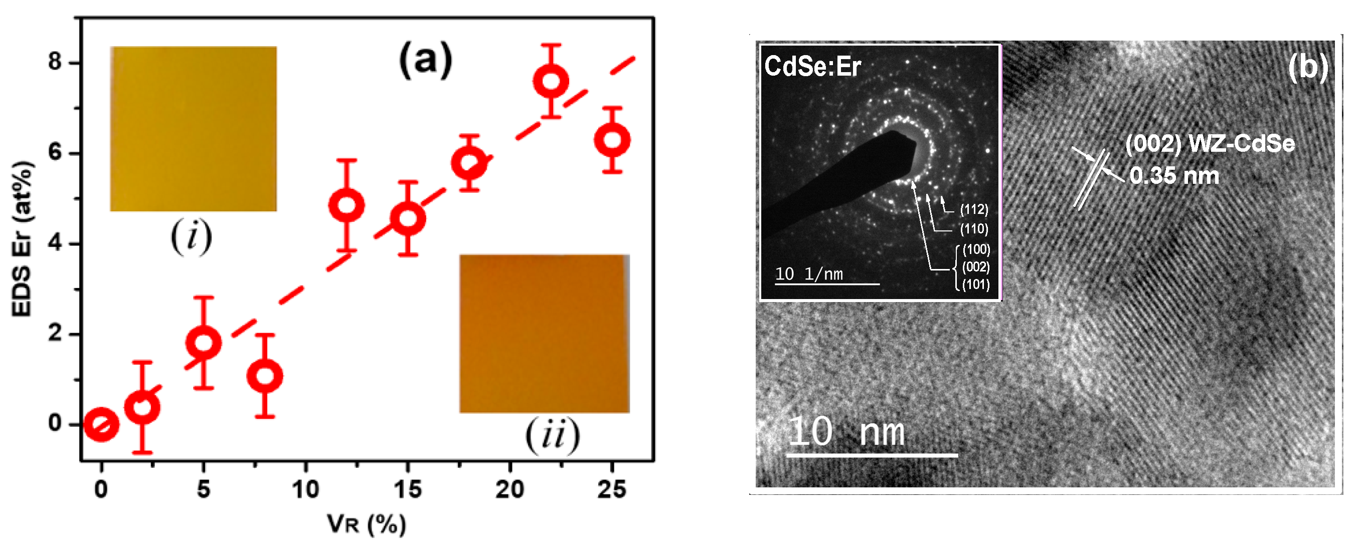
Figure 1. (a) EDS as a function of VR. Dashed line represents a linear fitting. (i) and (ii) insets illustrate images of the VR = 15% doped and undoped Cd1-xErxS samples, respectively. (b) TEM image of sample for x = 4.6 at%, where the (002) planes of wurtzite phase of CdSe are represented. The inset shows a SAED pattern of the WZ crystalline structure.
Magnetochemistry 09 00107 g001
Figure 2. (A) XRD pattern of the CdSe:Er film for x = 5.5 at%. The left inset shows the pattern for x = 0.6 at%. The right inset illustrates the unit cell of WZ-CdSe lattice. (B) (left axis) lattice parameters a and c versus x, (right axis) primitive unit cell volume versus x.
Magnetochemistry 09 00107 g002
Figure 3. (a) Phonon Raman spectra of the series of Cd1-xErxSe samples. (b) Raman spectrum of a representative CdSe:Er sample where the 1LO phonon mode and up to the third overtone are observed, a Raman signal from Er2O3 is revealed in the spectrum. The inset illustrates the deconvolution of the band at ~205 cm−1 in the 1LO mode (A) and the surface mode (B). (c) The 1LO (A) and the surface (B) modes positions against x. The low inset exhibits the 1LO mode position vs. x in a magnified scale. The right inset illustrates the A1LO mode oscillation.
Magnetochemistry 09 00107 g003
Figure 4. (a) Tauc method to calculate the direct energy band gap (Eg) of the Cd1-xErxSe for four values of x. The inset illustrates the optical transmittance (To) spectra for the same samples chosen for Eg calculation. (b) Direct band gap as function of x, the inset depicts the average crystal size (ACS) versus x plot.
Magnetochemistry 09 00107 g004
Figure 5. (a) Dark d.c. conductivity (σ) vs. inverse of absolute temperature (T). (b) Room temperature (RT) dark d.c. conductivity σ as a function of x.
Magnetochemistry 09 00107 g005
Figure 6. (a) Photoluminescence spectra of all the set of Cd1-xErxSe samples. (b) Energy position of the PL band maximum (left axis) and PL band intensity (right axis) versus x.
Magnetochemistry 09 00107 g006
Disclaimer/Publisher’s Note: The statements, opinions and data contained in all publications are solely those of the individual author(s) and contributor(s) and not of MDPI and/or the editor(s). MDPI and/or the editor(s) disclaim responsibility for any injury to people or property resulting from any ideas, methods, instructions or products referred to in the content.