
Magnetizable Membranes Based on Cotton Microfibers, Honey, Carbonyl Iron, and Silver Nanoparticles: Effects of Static Magnetic Fields and Medium-Frequency Electric Fields on Electrical Properties


Abstract
1. Introduction
2. Materials and Methods
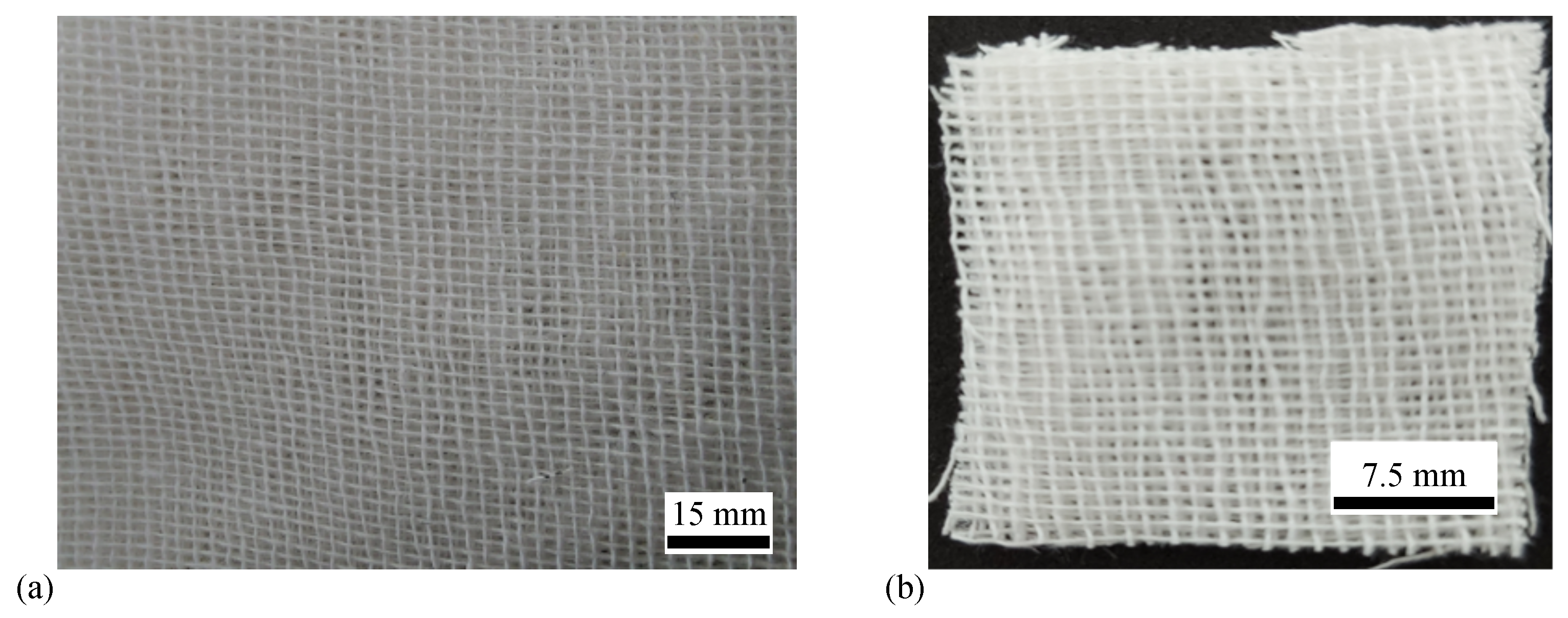
- Cotton microfibers made from sterile compression from Labormed Pharma S.A. in the form of gauze bandages (GB) manufactured by Shaoxing Gangfeng Hospital Products Co Ltd (China)(company, city, state, country), with threads of 100% pure cotton (Figure 1a). The mass density of the cotton microfibers was g/cm at 22, with a relative air humidity of 60 %.
- Lime honey with good antimicrobial and anti-inflammatory properties, which was obtained from bee harvests from lands with linden forests. The mass density was g/cm at 22.
- CI microparticles from Sigma-Aldrich Chemie GmbH (Taufkirchen, Germany), product code C-3518(city, state, country), with a minimum purity of 99.7 %. The particles had a spherical shape, with an average diameter of m. The bulk density was g/cm at 22.
- Silver microparticles from Sigma-Aldrich, Saint Louis, (Missouri, USA), product code 327085 (city, state, country)with a purity of at least 99.9 %. The particles also had a spherical shape and an average diameter of m at 22. The bulk density was g/cm at 22.
- Seven magnetic liquid suspensions were prepared in Berzelius glasses at various quantities of honey, CI, and silver microparticles, with the volumes and mass fractions listed in Table 1.
- The sterile compressions were soaked with the suspensions and the composite membranes M, with obtained (see Table 1 and Figure 2). As such, each membrane, except for M, contained honey; membranes M, M, and M contained silver microparticles, and membranes M, M, M, and M contained CI microparticles. The dimensions of each membrane are listed in Table 2.
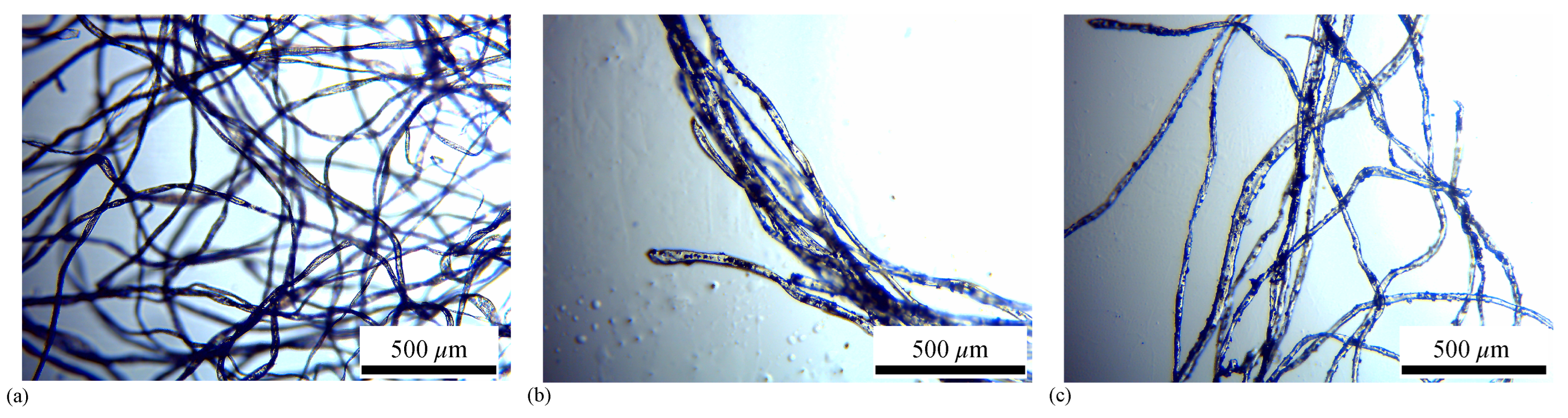
3. Optical Microscopy
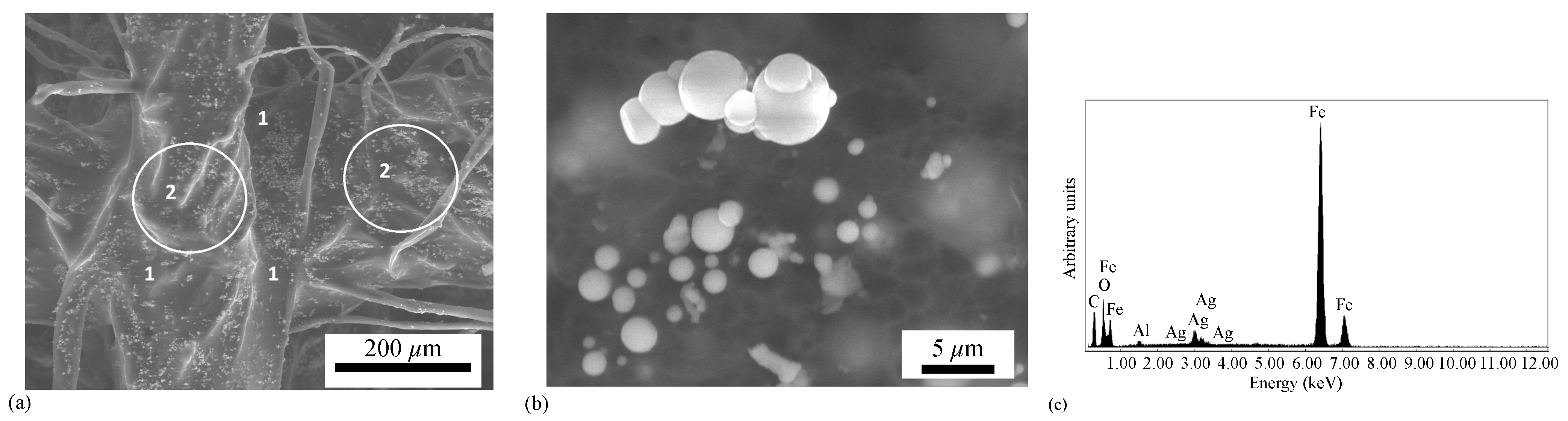
4. Microstructural Characterization and Elemental Analysis
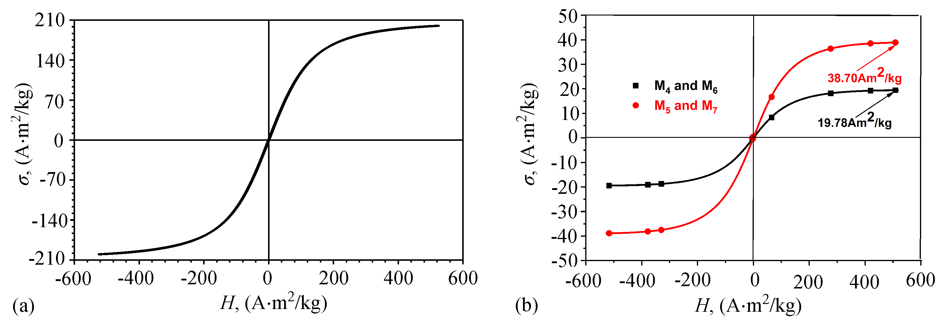
5. Magnetic Measurements
6. Fabrication of the Electrical Devices and the Experimental Setup
- A textolite plate coated with copper foil on one side, with dimensions of 100 mm × 75 mm × 0.8 mm, from Electronic Light Tech. The thickness of the copper foil was 35 m and the plate itself was based on epoxy resin, FR40type, reinforced with fiberglass.
- Membranes M, with (Table 1) with dimensions of 30 mm × 25 mm × 0.8 mm.
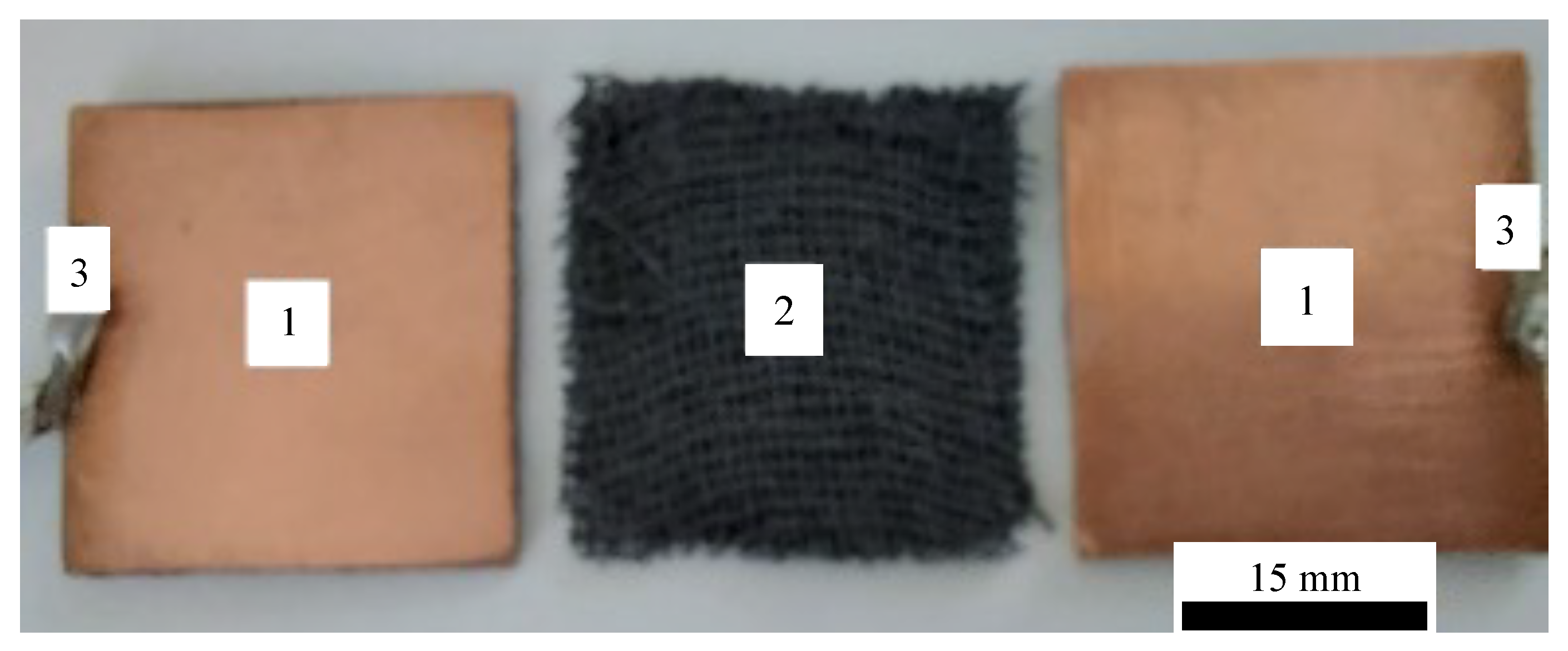
- Two pieces of dimensions 30 mm × 25 mm × 0.4 mm were cut from the textolite plate, and on each plate, two electrical conductors were welded, as shown in Figure 6.
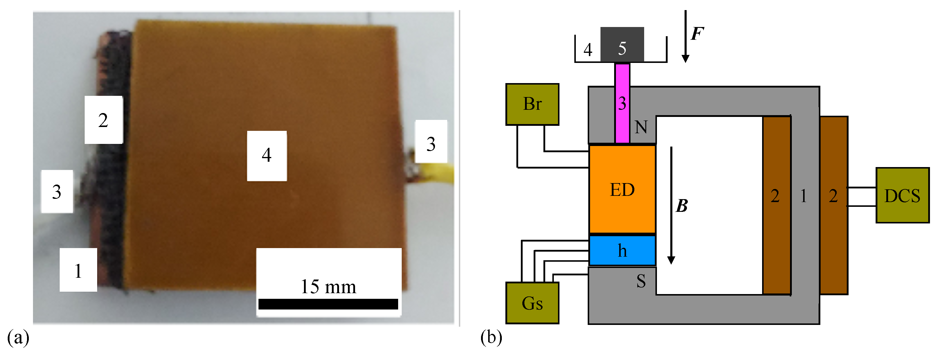
- The membranes were placed between each of the two electroconductive plates. As such, the electrical devices ED with were obtained. Figure 7a shows the electrical device with membrane M.
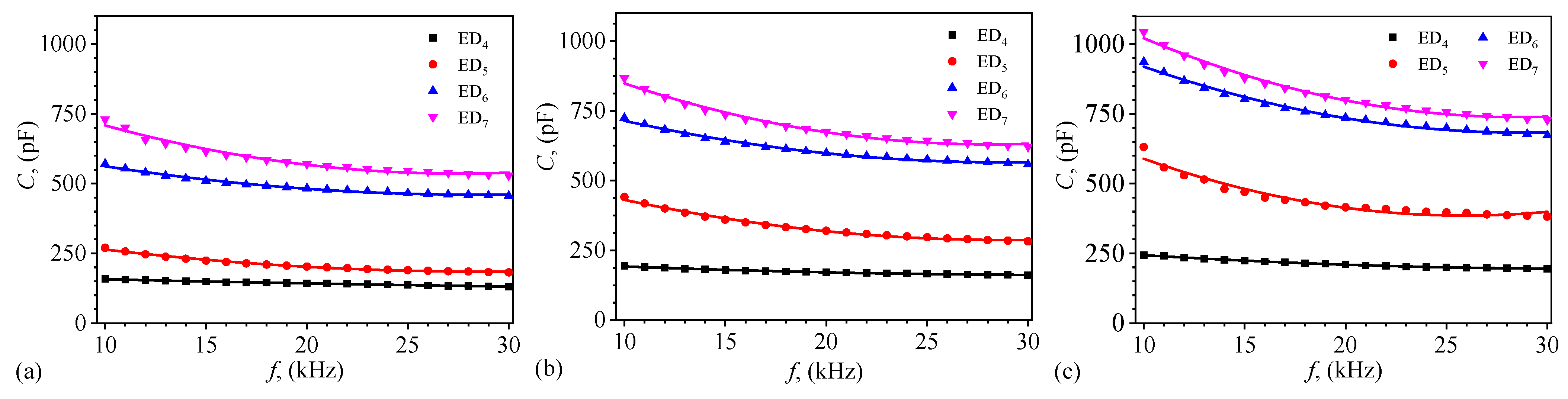
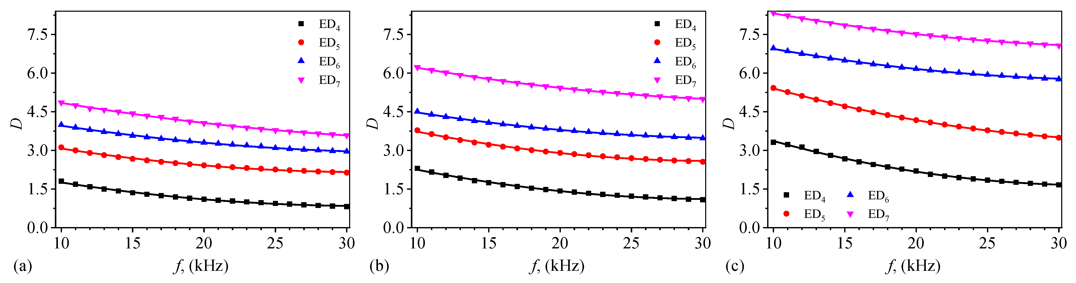
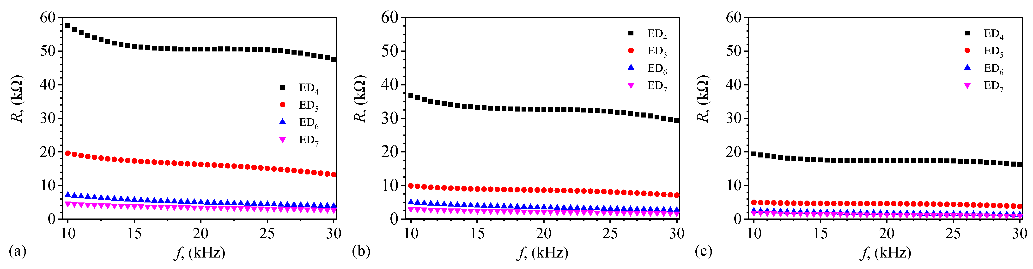
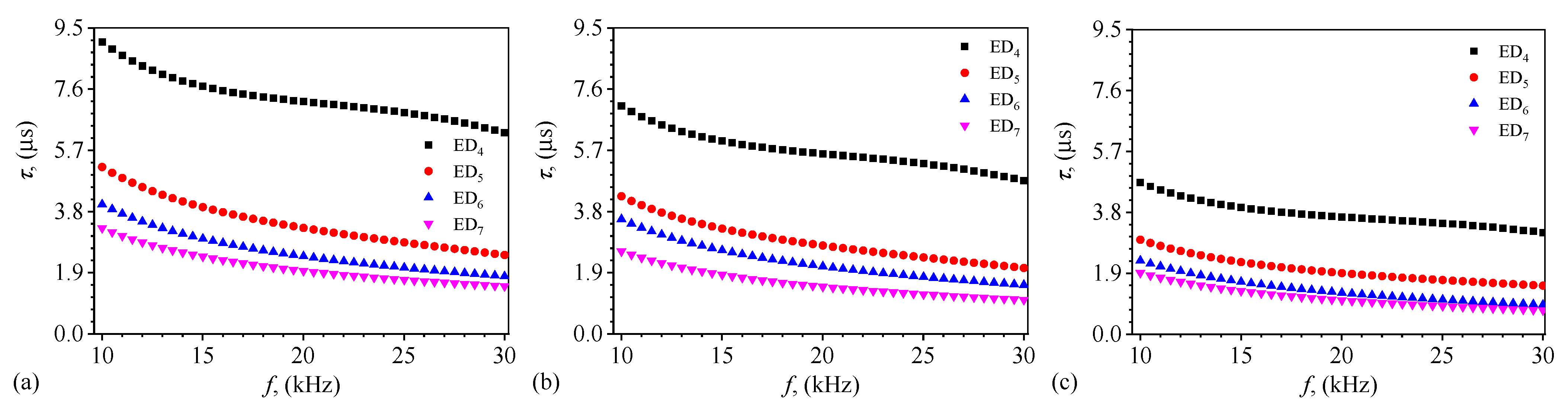
7. Results
8. Discussion
9. Conclusions
Author Contributions
Funding
Institutional Review Board Statement
Informed Consent Statement
Data Availability Statement
Acknowledgments
Conflicts of Interest
Abbreviations
| CMs | Composite membranes |
| CI | Carbonyl iron |
References
- Zahid, M.; Rashid, A.; Akram, S.; Rehan, Z.A.; Razzaq, W. A Comprehensive Review on Polymeric Nano-Composite Membranes for Water Treatment. J. Membr. Sci. Technol. 2018, 8, 1000179. [Google Scholar] [CrossRef]
- Wang, X.; Wang, N.; Li, X.; An, Q.F. A review of nano-confined composite membranes fabricated inside the porous support. Adv. Membr. 2021, 1, 100005. [Google Scholar] [CrossRef]
- Liu, L.; Tong, C.; He, Y.; Zhao, Y.; Lü, C. Enhanced properties of quaternized graphenes reinforced polysulfone based composite anion exchange membranes for alkaline fuel cell. J. Membr. Sci. 2015, 487, 99–108. [Google Scholar] [CrossRef]
- Huiya, W.; Ran, G.; Xinliang, Q. Preparation and Characterization of TiO2/g-C3N4/PVDF Composite Membrane with Enhanced Physical Properties. Membranes 2018, 8, 14. [Google Scholar]
- Qadir, A.; Le, T.K.; Malik, M.; Min-Dianey, K.A.A.; Saeed, I.; Yu, Y.; Choi, J.R.; Pham, P.V. Representative 2D-material-based nanocomposites and their emerging applications: A review. RSC Adv. 2021, 11, 23860–23880. [Google Scholar] [CrossRef]
- Ng, C.Y.; Ng, L.Y.; Mahmoudi, E.; Chung, Y.T. Fabrication of graphene-based membrane for separation of hazardous contaminants from wastewater. In Graphene-Based Nanotechnologies for Energy and Environmental Applications; Jawaid, M., Ahmad, A., Lokhat, D., Eds.; Elsevier: Amsterdam, The Netherlands, 2019; pp. 267–291. [Google Scholar] [CrossRef]
- Iojoiu, C.; Danyliv, O.; Alloin, F. Ionic Liquids and Polymers for Battery and Fuel Cells. In Modern Synthesis Processes and Reactivity of Fluorinated Compounds; Groult, H., Leroux, F.R., Tressaud, A., Eds.; Elsevier: Amsterdam, The Netherlands, 2019; pp. 465–497. [Google Scholar] [CrossRef]
- Fatima, A.; Yasir, S.; Khan, M.S.; Manan, S.; Ullah, W.; Ul-Islam, M. Plant extract-loaded bacterial cellulose composite membrane for potential biomedical applications. J. Bioresour. Bioprod. 2021, 6, 26–32. [Google Scholar] [CrossRef]
- Kim, S.; Wang, H.; Lee, Y.M. 2D Nanosheets and Their Composite Membranes for Water, Gas, and Ion Separation. Angew. Chem. 2019, 131, 17674–17689. [Google Scholar] [CrossRef]
- Elmahaisi, M.F.; Azis, R.S.; Ismail, I.; Muhammad, F.D. A review on electromagnetic microwave absorption properties: Their materials and performance. J. Mater. Res. Technol. 2022, 20, 2188–2220. [Google Scholar] [CrossRef]
- Wu, S.; Hu, W.; Ze, Q.; Sitti, M.; Zhao, R. Multifunctional magnetic soft composites: A review. Multifunct. Mater. 2020, 3, 042003. [Google Scholar] [CrossRef]
- Abdalla, I.; Yu, J.; Li, Z.; Ding, B. Nanofibrous membrane constructed magnetic materials for high-efficiency electromagnetic wave absorption. Compos. Part B Eng. 2018, 155, 397–404. [Google Scholar] [CrossRef]
- Haye, E.; Soon Chang, C.; Dudek, G.; Hauet, T.; Ghanbaja, J.; Busby, Y.; Job, N.; Houssiau, L.; Pireaux, J.-J. Tuning the Magnetism of Plasma-Synthesized Iron Nitride Nanoparticles: Application in Pervaporative Membranes. ACS Appl. Nano Mater. 2019, 2, 2484–2493. [Google Scholar] [CrossRef]
- Salidkul, N.; Mongkolthanaruk, W.; Faungnawakij, K.; Pinitsoontorn, S. Hard magnetic membrane based on bacterial cellulose—Barium ferrite nanocomposites. Carbohydr. Polym. 2021, 264, 118016. [Google Scholar] [CrossRef] [PubMed]
- Dongre, R.S.; Sadasivuni, K.K.; Deshmukh, K.; Mehta, A.; Basu, S.; Mashram, J.S.; Al-Maadeed, M.A.A.; Karim, A. Natural polymer based composite membranes for water purification: A review. Polym.-Plast. Tech. Mat. 2019, 58, 1295–1310. [Google Scholar] [CrossRef]
- Xue, Y.; Lofland, S.; Xiao, H. Comparative Study of Silk-Based Magnetic Materials: Effect of Magnetic Particle Types on the Protein Structure and Biomaterial Properties. Int. J. Mol. Sci. 2020, 21, 7583. [Google Scholar] [CrossRef]
- Giannelli, M.; Barbalinardo, M.; Riminucci, A.; Belvedere, K.; Boccalon, E.; Sotgiu, G.; Corticelli, F.; Ruani, G.; Zamboni, R.; Aluigi, A.; et al. Magnetic keratin/hydrotalcites sponges as potential scaffolds for tissue regeneration. Appl. Clay Sci. 2021, 207, 106090. [Google Scholar] [CrossRef]
- Sriplai, N.; Prinitsoontorn, S. Bacterial cellulose-based magnetic nanocomposites: A review. Carbohydr. Polym. 2021, 254, 117228. [Google Scholar] [CrossRef]
- Patiño-Ruiz, D.; Sanchez-Botero, L.; Hinestroza, J.; Herrera, A. Modification of Cotton Fibers with Magnetite and Magnetic Core-Shell Mesoporous Silica Nanoparticles. Phys. Status Solidi A 2018, 215, 1800266. [Google Scholar] [CrossRef]
- DeFrates, K.G.; Moore, R.; Borgesi, J.; Lin, G.; Mulderig, T.; Beachley, V.; Hu, X. Protein-Based Fiber Materials in Medicine: A Review. Nanomaterials 2018, 8, 457. [Google Scholar] [CrossRef]
- Bealer, E.J.; Kavetsky, K.; Dutko, S.; Lofland, S.; Hu, X. Protein and Polysaccharide-Based Magnetic Composite Materials for Medical Applications. Int. J. Mol. Sci. 2020, 21, 186. [Google Scholar] [CrossRef]
- Varghese, A.M.; Mittal, V. Surface modification of natural fibers. In Biodegradable and Biocompatible Polymer Composites; Shimpi, N.G., Ed.; Woodhead Publishing: Sawston, UK, 2018; pp. 115–155. [Google Scholar] [CrossRef]
- Dochia, M.; Sirghie, C.; Kozłowski, R.M.; Roswitalski, Z. Cotton fibres. In Handbook of Natural Fibres; Kozłowski, R.M., Ed.; Woodhead Publishing: Sawston, UK, 2012; pp. 11–23. [Google Scholar] [CrossRef]
- Bica, I.; Anitas, E.M.; Chirigiu, L. Hybrid Magnetorheological Composites for Electric and Magnetic Field Sensors and Transducers. Nanomaterials 2020, 10, 2060. [Google Scholar] [CrossRef]
- Bunoiu, O.M.; Anitas, E.M.; Pascu, G.; Chirigiu, L.M.E.; Bica, I. Electrical and Magnetodielectric Properties of Magneto-Active Fabrics for Electromagnetic Shielding and Health Monitoring. Int. J. Mol. Sci. 2020, 13, 4785. [Google Scholar] [CrossRef] [PubMed]
- Iacobescu, G.E.; Bica, I.; Chirigiu, L.M.E. Physical Mechanisms of Magnetic Field Effects on the Dielectric Function of Hybrid Magnetorheological Suspensions. Materials 2021, 14, 6498. [Google Scholar] [CrossRef] [PubMed]
- Pascu, G.; Bunoiu, O.M.; Bica, I. Cotton fibres. Magnetic Field Effects Induced in Electrical Devices Based on Cotton Fiber Composites, Carbonyl Iron Microparticles and Barium Titanate Nanoparticles. Nanomaterials 2022, 12, 888. [Google Scholar] [CrossRef]
- Bica, I.; Anitas, E.M. Electrical devices based on hybrid membranes with mechanically and magnetically controllable, resistive, capacitive and piezoelectric properties. Smart Mater. Struct. 2022, 31, 045001. [Google Scholar] [CrossRef]
- Cai, Q.; Yang, S.; Zhang, C.; Li, Z.; Li, X.; Shen, Z.; Zhu, W. Facile and Versatile Modification of Cotton Fibers for Persistent Antibacterial Activity and Enhanced Hygroscopicity. ACS Appl. Mater. 2018, 10, 38506–38516. [Google Scholar] [CrossRef]
- Cianciosi, D.; Forbes-Hernández, T.Y.; Afrin, S.; Gasparrini, M.; Reboredo-Rodriguez, P.; Manna, P.P.; Zhang, J.; Bravo, L.L.; Martinéz, F.S.; Agudo, T.P.; et al. Phenolic Compounds in Honey and Their Associated Health Benefits: A Review. Molecules 2018, 23, 2322. [Google Scholar] [CrossRef]
- Plachy, T.; Cvek, M.; Munstr, L.; Hanulikova, B.; Suly, P.; Vesel, A.; Cheng, Q. Enhanced magnetorheological effect of suspensions based on carbonyl iron particles coated with poly (amidoamine) dendrons. Rheol. Acta 2021, 60, 263–276. [Google Scholar] [CrossRef]
- Salem, A.M.H.; Ali, A.; Ramli, R.B.; Muthalif, A.G.A.; Julai, S. Effect of Carbonyl Iron Particle Types on the Structure and Performance of Magnetorheological Elastomers: A Frequency and Strain Dependent Study. Polymers 2022, 14, 4193. [Google Scholar] [CrossRef]
- Sista, K.S.; Dwarapudi, S.; Kumar, D.; Sinha, G.R.; Moon, A.P. Carbonyl iron powders as absorption material for microwave interference shielding: A review. J. Alloys Compd. 2021, 853, 157251. [Google Scholar] [CrossRef]
- Briguglio, M.; Hrelia, S.; Malaguti, M.; De Vecchi, E.; Lombardi, G.; Banfi, G.; Riso, P.; Porrini, M.; Romagnoli, S.; Pino, F.; et al. Oral Supplementation with Sucrosomial Ferric Pyrophosphate Plus L-Ascorbic Acid to Ameliorate the Martial Status: A Randomized Controlled Trial. Nutrients 2020, 12, 386. [Google Scholar] [CrossRef]
- Bruna, T.; Maldonado-Bravo, F.; Jara, P.; Caro, N. Silver Nanoparticles and Their Antibacterial Applications. Int. J. Mol. Sci. 2021, 22, 7202. [Google Scholar] [CrossRef] [PubMed]
- Ercuta, A. Sensitive AC Hysteresigraph of Extended Driving Field Capability. IEEE Trans. Instrum. Meas. 2020, 69, 1643–1651. [Google Scholar] [CrossRef]
- Genç, S. Synthesis and Properties of Magnethoreological (MR) Fluids. Ph.D. Thesis, University of Pitsburgh, Pittsburgh, PA, USA, 2003; p. 23. [Google Scholar]
- Chen, L.F.; Ong, C.K.; Neo, C.P.; Varadan, V.V.; Varadan, V.K. Microwave Electronics: Measurement and Materials Characterization, 1st ed.; Wiley: Hoboken, NJ, USA, 2004. [Google Scholar]
- Bica, I.; Anitas, E.M.; Averis, L.M.E. Tensions and deformations in composites based on polyurethane elastomer and magnetorheological suspension: Effects of the magnetic field. J. Ind. Eng. Chem. 2015, 28, 86–90. [Google Scholar] [CrossRef]
- Bica, I.; Anitas, E.M. Magnetic field and microstructural effects on the electrical capacitance and resistance of a quadrupolar electrical capacitor based on cotton fabrics and carbonyl iron microparticles. Smart Mater. Struct. 2022, 31, 125018. [Google Scholar] [CrossRef]
- Kchit, N.; Bossis, G. Electrical resistivity mechanism in magnetorheological elastomer. J. Phys. D Appl. Phys. 2009, 42, 105505. [Google Scholar] [CrossRef]
- Bica, I.; Anitas, E.M. Magnetic field intensity and γ-Fe2O3 concentration effects on the dielectric properties of magnetodielectric tissues. Mater. Sci. Eng. B 2018, 236–237, 125–131. [Google Scholar] [CrossRef]
- Bica, I.; Anitas, E.M.; Chirigiu, L.; Daniela, C.; Chirigiu, L.M.E. Hybrid magnetorheological suspension: Effects of magnetic field on the relative dielectric permittivity and viscosity. Colloid Polym. Sci. 2018, 296, 1373–1378. [Google Scholar] [CrossRef]
- Bica, I.; Anitas, E.M. Magnetic field intensity effect on electrical conductivity of magnetorheological biosuspensions based on honey, turmeric and carbonyl iron. J. Ind. Eng. Chem. 2018, 64, 276–283. [Google Scholar] [CrossRef]
- Bica, I.; Anitas, E.M. Light transmission, magnetodielectric and magnetoresistive effects in membranes based on hybrid magnetorheological suspensions in a static magnetic field superimposed on a low/medium frequency electric field. J. Magn. Magn. Mater 2020, 511, 166975. [Google Scholar] [CrossRef]


| Membrane | ||||||||
|---|---|---|---|---|---|---|---|---|
| M | 0.28 | 0.00 | 0.00 | 0.00 | 0.00 | 0.00 | 0.00 | 0.00 |
| M | 0.28 | 0.34 | 0.00 | 0.00 | 45.0 | 55.0 | 0.00 | 0.00 |
| M | 0.28 | 0.34 | 0.10 | 0.00 | 39.0 | 47.0 | 14.0 | 0.00 |
| M | 0.28 | 0.34 | 0.00 | 0.10 | 39.0 | 47.0 | 0.00 | 14.0 |
| M | 0.28 | 0.34 | 0.00 | 0.20 | 34.0 | 41.0 | 0.00 | 24.0 |
| M | 0.28 | 0.34 | 0.10 | 0.10 | 34.0 | 42.0 | 12.0 | 12.0 |
| M | 0.28 | 0.34 | 0.10 | 0.20 | 30.0 | 37.0 | 11.0 | 12.0 |
| Membrane | V (cm) | S (cm) | d (cm) |
|---|---|---|---|
| M | 0.28 | 7.50 | 0.037 |
| M | 0.62 | 7.50 | 0.082 |
| M | 0.72 | 7.50 | 0.096 |
| M | 0.72 | 7.50 | 0.096 |
| M | 0.82 | 7.50 | 0.109 |
| M | 0.82 | 7.50 | 0.109 |
| M | 0.92 | 7.50 | 0.122 |
Disclaimer/Publisher’s Note: The statements, opinions and data contained in all publications are solely those of the individual author(s) and contributor(s) and not of MDPI and/or the editor(s). MDPI and/or the editor(s) disclaim responsibility for any injury to people or property resulting from any ideas, methods, instructions or products referred to in the content. |
© 2023 by the authors. Licensee MDPI, Basel, Switzerland. This article is an open access article distributed under the terms and conditions of the Creative Commons Attribution (CC BY) license (https://creativecommons.org/licenses/by/4.0/).
Share and Cite
Bica, I.; Anitas, E.M.; Sfirloaga, P. Magnetizable Membranes Based on Cotton Microfibers, Honey, Carbonyl Iron, and Silver Nanoparticles: Effects of Static Magnetic Fields and Medium-Frequency Electric Fields on Electrical Properties. Magnetochemistry 2023, 9, 19. https://doi.org/10.3390/magnetochemistry9010019
Bica I, Anitas EM, Sfirloaga P. Magnetizable Membranes Based on Cotton Microfibers, Honey, Carbonyl Iron, and Silver Nanoparticles: Effects of Static Magnetic Fields and Medium-Frequency Electric Fields on Electrical Properties. Magnetochemistry. 2023; 9(1):19. https://doi.org/10.3390/magnetochemistry9010019
Chicago/Turabian StyleBica, Ioan, Eugen Mircea Anitas, and Paula Sfirloaga. 2023. "Magnetizable Membranes Based on Cotton Microfibers, Honey, Carbonyl Iron, and Silver Nanoparticles: Effects of Static Magnetic Fields and Medium-Frequency Electric Fields on Electrical Properties" Magnetochemistry 9, no. 1: 19. https://doi.org/10.3390/magnetochemistry9010019
APA StyleBica, I., Anitas, E. M., & Sfirloaga, P. (2023). Magnetizable Membranes Based on Cotton Microfibers, Honey, Carbonyl Iron, and Silver Nanoparticles: Effects of Static Magnetic Fields and Medium-Frequency Electric Fields on Electrical Properties. Magnetochemistry, 9(1), 19. https://doi.org/10.3390/magnetochemistry9010019