Abstract
We have recently shown that a hybrid magnetic thin film with orthogonal anisotropies presenting weak stripe domains can achieve a high degree of controllability of its ferromagnetic resonance. This work explores the origin of the reconfigurability through micromagnetic simulations. The static domain structures which control the thin film resonance can be found under a deterministic applied field protocol. In contrast to similar systems reported, our effect can be obtained under low magnetic fields. We have also found through simulations that the spin wave propagation in the hybrid is nonreciprocal: two adjacent regions emit antiparallel spin waves along the stripe domains. Both properties convert the hybrid in a candidate for future magnonic devices at the nanoscale.
1. Introduction
In the late 1900s of the last century, there has been a turning point in magnetic materials research from the in-plane magnetized materials to materials having out-of-plane components due to its perpendicular magnetic anisotropy (PMA). A gaining in recording density was behind this transition [1]. The preferential research has commonly involved hard magnets where the PMA is so strong that it overcomes the demagnetizing energy due to charges. Typical examples are Pt, Pd alloys with Co or Fe [2] or multilayers formed by a sequential arrangement of magnetic and non-magnetic materials [3]. However, these materials need costly growth procedures and post-growth processes and the PMA involves using high magnetic fields for its control. In this context, the use of materials with low PMA is beneficial. A plethora of low PMA materials can be found: the former materials [2,3] with different growth conditions and/or that are subjected to another post-treatments, GdFe [4], Permalloy (Ni80Fe20) [5], CoSiB [6], CoFeZr [7], FeGa [8], TbFeGa [9], FeN [10], c-Co [11] and some slight variants of them. Besides these materials, our group has also used NdCox [12] and FeSix, [13] and YCo5 [14].
The dynamical properties of magnets have been long used as a method to obtain the magnetic fundamental parameters of the materials [15,16] and/or to aid in the designing of devices [17]. However, compared to studies at high magnetic fields, the analysis of dynamic properties under saturation is comparatively scarce in the literature. Some exceptions can be found in references [11,18,19,20]. This could mainly be due to its intrinsic complexity and the lack of appropriate tools for analysis. In the last few years, some groups have been promoting a more careful study of the physics in the low-field range due to the possibilities that the developed domains are carrying with [21,22,23,24,25].
Nowadays, there is a need for obtaining magnet-based logic and filtering operations of signal carriers with processing units holding some degree of versatility at the nanoscale scale. Obtaining reconfigurable magnetic systems is one of the milestones needed for improving the versatility and efficiency of such gigahertz devices. This work will focus on a material which presents some of the above-mentioned peculiarities. Micromagnetic simulations will help us in understanding the origin of some of the interesting dynamical properties that weak PMA NdCox alloys coupled to a 10 nm thick Permalloy film present. As low thickness Permalloy holds in-plane magnetic anisotropy (IMA), we will deal with a hybrid magnet distinguished by its coupled regions with orthogonal anisotropies. In particular, we will treat the capability of this system for tuning its ferromagnetic resonance (FMR). There is a field range where the system can resonate at will at two different values under the same applied magnetic field. Although other proposals of reconfigurable systems can be found in the recent literature, they are helped by costly nanoscale shaping [26] and mainly use only IMA materials (resulting in a lower domain density as mentioned above) [27]. Simulations will also show that these hybrids have another useful property in the GHz regime. At remanence, they present the possibility of using their stripe domains as nonreciprocal spin-wave nanochannels. Both properties, reconfigurability and nonreciprocity, can be used in the improvement of logical devices and interconnections for beyond-CMOS architectures [28].
We will start with a brief discussion about the nanodomain sizes which can be obtained using low PMA NdCox alloys. We will focus here on the most common cobalt ratio: xCo = 5 (Section 2.1). After, we will present the peculiar static magnetic distribution of NdCox and Permalloy when they are placed in proximity, separated just by a thin non-magnetic material (Section 2.2). To continue, we will describe how this static magnetization modulates the dynamic behavior of the whole system resulting in reconfigurability (Section 2.3.1) and nonreciprocity (Section 2.3.2). Finally, some possible improvements are listed and the conclusions will be given.
2. Results and Discussion
2.1. Nanodomain Size
One of the main issues that the low PMA thin films present in order to host domains at the nanoscale is that to develop a domain structure with out-of-plane components (called weak stripe domains), the sample must be thicker than the so-called critical thickness: tc [29]. If the film is not thick enough, the samples prefer to rest in the monodomain state (or at list in-plane magnetized state due to the shape anisotropy). tc is dependent on the PMA/demagnetizing energy ratio (the so-called quality factor Q) and the exchange constant. The onset of weak stripe domains can be viewed as a phase transition. Its treatment leads to some analytical expressions [30] and algebraic equations [31] which can be used to obtain tc. The repeated domain structures of these weak PMA materials can be characterized by a critical spatial wavelength (λc) when the film thickness is close to the critical one (tc). So, there is a minimal wavelength for stripe domains as the thickness is lowered (keeping the film magnetic parameters fixed).
From the theoretical point of view, λ can be found by numerical means [32] or by using some simplifying assumptions on the spatial evolution of magnetization inside the thin film [33]. As a general rule, it can be said that as PMA gets bigger, both tc and λ decrease. Two origins are behind this effect: (i) a thinner film is needed to develop stripe domains and, (ii) λ is a decreasing function of thickness (while the film is not too thin: see next paragraph and [30]).
Even if the modern trends followed by the magnetism community are to increase the miniaturization of devices until the nanoscale, unfortunately the low PMA thin films just form domains ranging from a few tens of nanometers to a few hundreds. On the contrary, domains in high PMA materials can have out-of-plane magnetization components even in few-nm-thick materials. But the price to pay in these ultrathin materials is that the exchange energy has an increased weight in the total energy of the samples. This fact widens the stripe domains, and the domain size/thickness ratio becomes much greater than one [34]. As we will see shortly, this ratio can be close to 1.5 in low PMA materials. Among the low PMA materials used in our laboratory, the harder one is NdCo5. Under the common sputtering parameters used for its growing we have observed a stripe domain structure even in a 29 nm thick film. The FFT of the corresponding MFM image results in 45 nm wide domains (implying λ to be 90 nm). We will begin by characterizing the domains of the NdCo5 composition at the remanent state.
We have selected two thicknesses close to the experimental one above-mentioned to illustrate the behavior close to criticality: 35 nm and 45 nm. The free GPU-based MuMax3 micromagnetic simulator was used for the simulations [35]. Among the MuMax3 outputs, the total energy density and its components can be found. Figure 1a displays the calculated total energy density weak stripe domain structure as a function of its wavelength λ. Blue and red arrows indicate the wavelength of the minimal total energy density, λ*, for the 35 nm thick and the 45 nm thick nm at a given exchange constant (A = 7 × 10⁻¹² J/m). When the simulated film thickness approaches the nominal one growth, 29 nm, we can see that the predicted λ*, which gets closer to the one measured. In particular, the 35 nm thick (45 nm thick) film presents a λ* equal to 105 nm (127 nm). As thinner films are modelled, the experimental domain width/thickness ratio (1.55) is approached (from below). Figure 1a also reflects that for changing, λ* is more effective of a thickness variation than an exchange constant variation. This conclusion can be extracted from the comparison between i) the red (A = 5 × 10⁻¹² J/m) and black curves (A = 7 × 10⁻¹² J/m), having equal thickness and ii) the blue (t = 35nm) and black curves (t = 45nm), both being calculated with A = 5 × 10⁻¹² J/m. For similar relative changes of both A and t (~25%), the relative change of λ* is around four times lower in the first case (~5/127 = 4%).
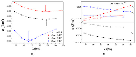
Figure 1.
(a) Variation of the total energy density as a function of the stripe domain wavelength for a 45 nm thick (red and black) and 35 nm thick (blue) NdCo5; (b) energy density contributions for 45 nm thick (full dots) and 35 nm thick (empty squares) NdCo5 films. The exchange is kept constant for (b). No external magnetic field is considered.
On the other hand, Figure 1b reports the behavior of the three individual terms, summing up in etot versus λ− etot has contributions from PMA (eK/black), the demagnetizing energy (eD/blue) and the exchange energy (eA/red). Empty symbols belong to the 45 nm thick film and the empty ones to the 35 nm thick film [35]. In Figure 1b, the exchange constant, A, was kept fixed to 7 × 10⁻¹² J/m. The saturation magnetization and perpendicular anisotropy used can be found in the methods section. As shown in Figure 1b, the exchange interaction favors bigger λ while the demagnetizing term promotes smaller ones. The anisotropy energy density is more sensitive to λ variations in the low λ range: here, regions of the material with magnetization not aligned to the easy axis represent a meaningful contribution to the total volume and increase the energy density. Another conclusion extracted from Figure 1b is that thinner NdCo5 films result in greater absolute values of the energies involved. At the same time, the second derivate of the total energy density grows until the film becomes completely in-plane magnetized at tc. We did not continue to further the analysis of the thickness impact due to non-negligible mistakes for the predicted tc.
2.2. Static Properties of Stripe Domains
The energetics found in the previous subsection come from the inner distribution of NdCo5 magnetization. This distribution is visualized in Figure 2 where the three magnetization components of a 65 nm thick NdCo5 layer in the (0YZ) plane transverse to the stripe direction (0X) are shown. Only one full wavelength of the stripe domains, λ*, is considered at the remanent (MFM measurements reveal a stripes wavelength ~140 nm [36]). Figure 2a shows the cartesian axes used through this work and the direction used for the saturating external field. The out-of-plane component of the magnetization (mz) can be observed in Figure 2b. A big part of the stray field that the Permalloy feels (placed on top of the Al/NdCox bilayer) is due to that component. Figure 2c shows the in-plane magnetization component perpendicular to the stripes main direction (my). Its value lies in the lowering of the demagnetizing energy that it affords. The triangular domains inside Figure 2c are commonly denoted as closure domains (due to its flux closing properties) or Néel caps (due to the nature of its domains walls) [11]. Finally, Figure 2d shows the domain magnetization along the stripes (mx). The main difference between weak PMA and hard PMA materials is that in the latter case, only the magnetization component of Figure 2b is markedly different from zero.
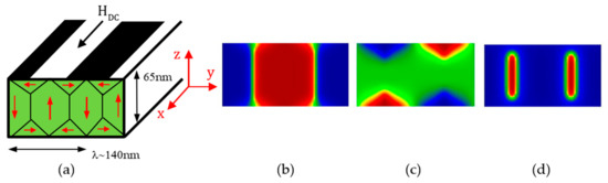
Figure 2.
Sixty-five nm thick NdCo5 remanent state: (a) reference axes, applied field direction and sketch of the stripe domain structure; (b) out-of-plane magnetization, in-plane components of the sample: (c) perpendicular; (d) parallel to the applied field HDC.
The main topic of this work is the using of magnetic materials presenting weak stripe domain structures in the fabrication of devices working in the GHz range [37]. However, NdCox alloys (due to its rare-earth content) have a very broad resonance which prevents its use as a good material for dynamics. We have recently shown how the growing of hybrid systems can help in surpassing this difficulty [36]. If another material with the appropriate dynamic properties (Permalloy in our case) is grown on top of NdCox, the stripe domain structure of the latter is, at least partially, imprinted on Permalloy. In this way, Permalloy achieves the nice properties of stripe domains. We will consider a 10 nm thick Permalloy through this work. Notice that the interaction between the top and bottom layers must not be through direct contact: in this case there would be a tight movement of Permalloy and NdCox which affects Permalloy dynamics. The exchange interaction between the two materials results in a globally poor dynamic performance. Due to this feature, we have used a few-nm-thick sputtered Al film as a separator. Al thickness also serves to control the NdCox stripe domains imprinting on Permalloy: a thicker Al lowers the NdCox stray field on Permalloy.
Figure 3 summarizes the magnetization state of the hybrid when a 10 nm thick Permalloy is coupled to a 65 nm thick NdCo5 film through a 2.5 nm thick Al separator. We have selected this Al thickness among the experimental ones used [36] because here, the effects of the NdCo5 stray field on Permalloy are the biggest ones. Before being plugged to NdCox, Permalloy is magnetized completely in-plane (due to its IMA). Once placed in close proximity to NdCox, the average in-plane Permalloy magnetization is parallel to the stripe domains’ direction set in by HDC (shown in Figure 2a). This characteristic is observed regardless of the IMA Permalloy easy axis direction and it is due to the so-called rotatable anisotropy of stripe domains [13]. On the other hand, Permalloy also takes part in some sense in the uppermost closure domains of the whole sample (Figure 3b).
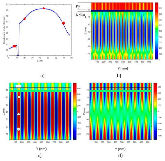
Figure 3.
Remanent state of the NdCo5-(2.5 nm-Al)-Py film; (a) 1-D profile of the out-of-plane angle through the thickness along an upwardly magnetized domain; (b,d) in-plane magnetization components: parallel, perpendicular to the previously applied HDC; (c) out-of-plane magnetization. Red symbols of (a) are in correspondence with the white ones of (c). The magnetization units are KA/m. Black dashed lines in (c,d) indicate the place where the 1-D cuts in Figure 6b,c are obtained.
It means that the weak stripe domain distribution is imprinted partially in Permalloy and, due to its low anisotropy, Permalloy develops a 1-D periodic structure of magnetization. In addition to the non-zero My inside the closure domains, an out-of-plane Mz is developed (Figure 3c) and Mx becomes lower than MS (Figure 3b). In Figure 3a we can see the 1-D variation of the angle between the magnetization and the film plane along the normal of the film. The variation is shown only for one of the domains with its magnetization pointing up (red domains in Figure 3c). Observe first that the out-of-plane angle does not cancel inside the closure domains (red circle and red star). These non-zero values imply that the magnetization at these places also contribute to the stray field in Permalloy. Secondly, the middle of the sample (red triangle) has a similar configuration to the one exhibited by hard PMA materials: the magnetization here is almost completely out-of-plane (in fact, the out-of-plane magnetic distribution of NdCo5 in the trilayer is similar to its distribution as a single layer). Finally, the red rectangle indicates that the average Permalloy magnetization is rotated 15° from the film plane. This angle is mainly the result of the balance of the action on Permalloy magnetization of both the NdCo5 stray field and the Permalloy demagnetizing field. Figure 3c contains white symbols signaling the positions where the red symbols of Figure 3a are placed. To complete this picture, we show in Figure 4a the full 3-D view of the whole structure and in Figure 4b, a zoom of the Permalloy and the NdCo5 top part with unitary vectors [38].
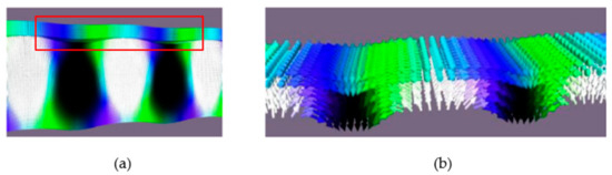
Figure 4.
Remanent state of the NdCo5-(2.5 nm-Al)-Py; (a) global image of stripe domain structure; (b) zoom of the previous image (red triangle in (a)) containing unitary vectors [38].
2.3. Dynamics of Stripe Domain Dynamics
Once the static magnetic structure is characterized, one can go ahead with studying the dynamic properties of the stripe domains. The study is done by using the following transversal configuration where there are two applied magnetic fields: (i) a static one along a particular direction (the above mentioned HDC) and (ii) a small time-varying field applied crossed to the former (hpulse). Both are applied in-plane.
We will only focus on the case where HDC is applied along the NdCox in-plane hard axis: experimentally, the biggest effects have been found for this particular case [36]. Following the procedure reported in the methods section, we keep the magnetic system under linear response by applying a low amplitude hpulse: 1mT. The hpulse temporal variation follows a decreasing exponential to sample a broad frequency range with a unique numerical experiment (see Figure 5a). The temporal magnetic response (mz) is followed for 15 ns. In Figure 5b we can see mz(t) for three HDC values of decreasing amplitude. The obtained mz(t) is interpolated to values at regularly spaced times with Matlab© (this step must be done due to the fact that MuMax3 uses a variable time step procedure for the integration of the magnetization equations of motion). The interpolated mz(t) is then Fourier transformed to find the amplitudes in Fourier space. Figure 5c presents the corresponding amplitudes of Permalloy (red) and NdCo5 (blue), normalized to the spectral for the amplitude of hpulse, for the HDC = 50nm case.
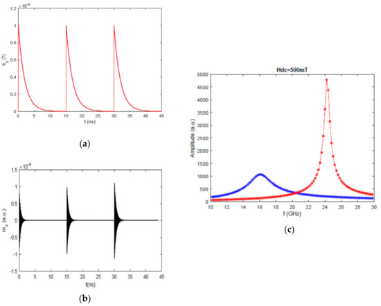
Figure 5.
NdCo5-(2.5 nm-Al)-Py; (a) temporal evolution of hpulse applied to the hybrid structure; (b) out-of-plane, mz, dynamic Py response for HDC = 80, 60 and 50 mT (from left to right); (c) amplitude of the FT response of NdCo5 (blue) and Permalloy (red) under 50 mT.
2.3.1. Reconfigurability
When the FMR is tracked, as HDC is varied, the VNA-FMR (fres vs. H) has a hysteretic behavior in analogy to the vibrating sample magnetometer hysteresis curves (M vs. H) [36]. The results of our simulations on a Py-(10nm-Al)-NdCox trilayer (see methods) also account for the hysteretic behavior. Figure 6a includes the low field view of the change of the trilayer FMR when HDC is reduced from HMAX to –HMAX (black curve) and HDC increases from –HMAX to HMAX (red curve). As the saturation field of the system is close to 150 mT, HMAX was set to 800 mT. Despite the low density of simulation points, we can see that there is a difference in resonances for the descending-HDC (black) and the ascending-HDC (red) branches. We find that if HDC is 50 mT, the resonances are ~5.7 GHz (~6.1 GHz) for the ascending-HDC (descending-HDC) applied fields. This implies a relative change of 6.6%. Experiments reflect a greater frequency difference: it can reach up to 25% for the used thin film geometry [36]. This discrepancy suggests that further magnetic parameters fitting needs to be done in these simulations.
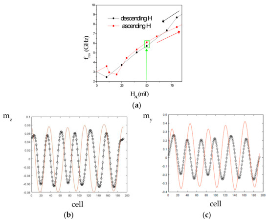
Figure 6.
65nm-NdCox-(10nm-Al)-Py: (a) Permalloy ferromagnetic resonance (FMR) evolution versus external field, 1-D profiles of reduced magnetization components under 50 mT; (b) mz; (c) my profiles are extracted from the black dashed lines at Figure 3c,d. In all Figures, black (red) colors belong to the descending-HDC (ascending-HDC) magnetic field branch of (a).
Despite these divergences between the simulations and experiments, some conclusions can be obtained. What is the origin of this FMR difference? An answer to this question is reached by observing the characteristics of the two states of Figure 6a surrounded by a green rectangle. Both states are under the same field HDC (50 mT) but they have a different magnetic history. Figure 6b,c show 1-D cuts of two Permalloy reduced magnetization components: mz and my. The black (red) color indicates the results for the descending-HDC (ascending-HDC) branch. The values are taken from the black dashed lines in Figure 3c,d. The out-of-plane component, mz, is the one which better characterizes the dipolar interaction of NdCox and Permalloy through Al. On the other hand, my gives a measure of the capability of NdCox to avoid magnetic charges. As can be seen, the ascending-HDC branch exhibits greater my and mz than the descending-HDC branch.
It must be taken into account that the source of the periodical motion of magnetization around its equilibrium value is the so-called internal field [35]. Each energy term contributes to the total internal field with its own effective field. So, as a result of the difference in the static magnetization in the two states considered in Figure 6a, the internal field felt by Permalloy is different for the ascending-HDC and descending-HDC states. Roughly speaking, it can be said that the magnetization of the ascending-HDC state has an increased vortex character when compared to the magnetization of the descending branch. The greater vorticity of NdCox magnetization implies a lowering in: (i) the NdCox stray field on Permalloy; (ii) the Permalloy demagnetizing field (both resulting from the convolution of the corresponding magnetization and a geometrical tensor: ); (iii) and the Permalloy exchange field (set by the second spatial derivate of Permalloy magnetization). On the other hand, there is an increase in the anisotropy field of Permalloy (proportional to mx2) [35]. All of these four fields act on the Permalloy magnetization. The fact that the FMR of the ascending-HDC state is the lowest means that the three former mentioned anisotropy fields cannot counterbalance the action of the anisotropy field in stablishing the Permalloy FMR.
We performed another kind of analysis of the hysteretic behavior of the fres vs. HDC curves. We excited the whole film with a sinusoidal hAC field of amplitude 1mT (Figure 7a). The individual FMR of each state was accounted for in hAC. Along Figure 7, the results marked with a green (blue) color belongs to the descending-HDC (ascending-HDC) state under HDC = 50 mT. Even if the whole temporal evolution is saved (Figure 7b), we just analyzed the stationary range inside the colored rectangles (Figure 7c,d). The temporal evolution of the average Permalloy magnetization (red curves) along hAC (black curves) for these two states results in two different elliptical motions of mx at each FMR. The ellipses are the combined result of a sinusoidal my(t) with a different amplitude and different phase relative to hAC(t). The ascending-HDC state has an elliptical motion of lower amplitude and lower my-hAC dephasing. These two facts confirm the interpretation given above: the ascending-HDC state has the lowest internal field amplitude.
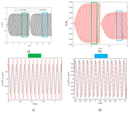
Figure 7.
NdCox-(10nm-Al)-Py: (a) sinusoidal hACx temporal evolution for: descending-HDC (0–7.5 ns)/ascending-HDC (7.5 ns–15 ns); (b) corresponding average my(t) in Permalloy, joint temporal stationary variation of average my in Permalloy and hAC; (c) descending-HDC (green); (d) ascending-HDC (blue).
With this change in FMR, the hybrid trilayer can be used in future reconfigurable resonators (with performance at relatively low magnetic fields). Its working principle is as follows: once the system is set at one frequency under a given field strength (here called operation-field: ~40 mT [36]) reconfigurability is achieved due to a so-called erasing-field. The erasing-field must match two characteristics: (i) it may be strong enough to put the system in the reversible part of the hysteresis loop: ~75 mT [36]; (ii) it must be antiparallel to the actual average magnetization of the stripe domains: ±mx. Once the erasing-field is applied and the applied field returns to the operating-field value, the hybrid will work at the other available FMR.
2.3.2. Nonreciprocity
Finally, we want to point out another interesting characteristic of the hybrid material presented. As will shortly be proved, simulations show that our hybrid system offers nonreciprocity in the spin waves emitted from an exciting antenna. This property is useful in the building up of logic devices, switches and interconnects. Behind the motion of the whole magnetization (the FMR mode) a motion of the magnetization at selected parts inside the sample can be also achieved [39]. This motion is carried by spin waves. There is a recent interest in using the domain walls as channels of spin waves motion through field confinement [23]. Due to the especial geometry of the stripe domains (see Figure 2a), we have explored the capability of our weak stripe domains to channel spin waves.
The numerical experiment has been done again on the NdCox-(10nm-Al)-Py trilayer using only its remanent state. The spin wave motion has been performed by applying hAC only locally (see Method section). Figure 8 shows the obtained results for a hAC frequency equal to 2.5 GHz. A temporal snapshot of Δmy is presented: the difference between the reduced magnetization parallel to hAC, my(τ), and its equilibrium value my(τ = 0). Figure 8 give us two characteristics of the excited spin waves: (i) spin waves mainly propagate along one sense , for a given domain (along the other sense, −, spin waves are highly damped); (ii) the allowed are antiparallel in two neighboring domains (when the blue curve represents the guided spin waves along , the red curve represents spin waves along −). When analyzing the distributions of mx and Δmx it can be stated that the allowed spin waves excited by the local hAC at a given domain obey the following law: = × [40]. Here, denotes the film normal and the reduced magnetization of the Permalloy domains. The spin wavelength reported in Figure 8, λSW, is close to 122 nm for both Permalloy domains. The wavevector is parallel to the previously applied field HDC (which at the same time sets the stripe domain/spin wave channel direction) and its module is 51 rad×μm−1. The imaging of the spin waves at this spatial scale can be reached with X-ray techniques as recently demonstrated [41].
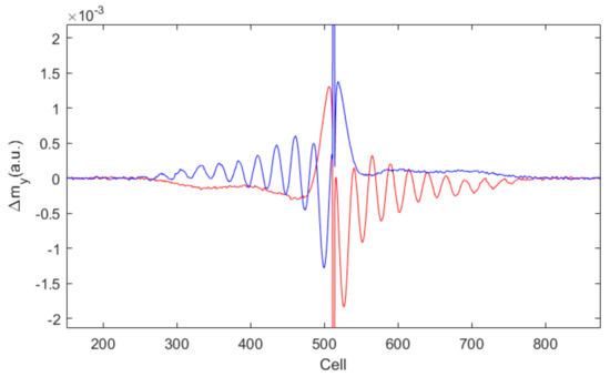
Figure 8.
NdCox-(10nm-Al)-Py. Temporal snapshot of the deviation of the y-component of the Permalloy reduced magnetization from its equilibrium value. The exciting field frequency is 2.5GHz. HDC = 0 mT.
Several origins have been found for explaining nonreciprocity in magnetic multilayers: interfacial-DMI exchange, spin pumping-based nonreciprocal damping, dipolar interactions or superficial anisotropies [42] and the nonreciprocal emission of waves by the antenna [43]. While the first two possibilities do not apply to our simulations (as they imply the existence of other kinds of materials) the three later ones are possible candidates. It is known that Ni-Al and Co-Al alloys form at room temperature, so the Al diffusion in Permalloy and NdCox cannot be neglected [44,45]. Interdiffusion will decrease the actual magnetic volume of the layers and/or promote the creation of different magnetic parameters at interfaces. Our micromagnetic simulations assume that the Permalloy and NdCox parameters are uniform so there is no room for special superficial parameters causing nonreciprocity (although they can be added to evaluate its influence and to better fit the experimental results). On the other hand, it must be considered that the NdCox stray field is non-homogeneous along the film normal: its magnitude gets lower as we move away from the Permalloy-Al interface. The effect of this decay could be cast in terms of an effective superficial anisotropy or a graded material [46]. It is likely that the magnetization in Permalloy is parallel to the stray field of NdCox (which sustains the interaction between Py and NdCox in our system) and it makes the major contribution to the internal field felt by Permalloy. Further studies need to be taken to confirm this hypothesis and quantify the influence of each source.
For future research, several directions can be highlighted. The resonant frequency can be boosted by thin film patterning [47] or by using synthetic antiferromagnets (SAF) [48] and ferrimagnets [49] instead of Permalloy. Another promising area of research is the light control of magnetism which allows for reaching the faster terahertz range [50]. In this sense, stripe domains in high Q materials have been rotated by light pulses recently [51]. On the other hand, a higher miniaturization level could be achieved by an extension of spin waves to the pure exchange driven regime which results in lower wavelengths [52]. Finally, in order to build highly energy efficient spin-wave devices, voltage driven magnets should be fabricated [53,54].
3. Conclusions
In summary, we have shown how a hybrid magnetic material presenting weak stripe domains can exhibit the reconfigurability of certain functions in the GHz range. The system works thanks to the inherent crossed anisotropies of the system. These combined anisotropies allow the selection of different internal field strengths in the system through a proper magnetic history. We showed that reconfigurability is achieved under a magnetic field strength one order of magnitude lower than in previous systems [55]. The nonreciprocal emission of spin waves was also numerically shown, originated by interdiffusion effects at interfaces, inhomogeneity of stray field from the PMA material and/or the nonreciprocal emission of spin waves from the antennas. These two characteristics (reconfigurability and nonreciprocity) convert our hybrid system in a candidate for future magnonic devices.
4. Materials and Methods
Micromagnetic simulations were performed with the following magnetic parameters of our former work [36]: γ is 15.9 × 10¹⁰ radT−1s−1; for NdCo5: K⊥ = 16.2×10⁴ J/m3, MS = 1000 KA/m, A = 0.7 × 10⁻¹¹ J/m; for Py: Ku = 423 J/m3, MS = 846 KA/m, A= 1.2 × 10⁻¹¹ J/m; for NdCox we tentatively used K⊥ = 5.4 × 10⁴ J/m3, MS = 390 KA/m, A = 0.35 × 10⁻¹¹ J/m. γ is the gyromagnetic ratio, K⊥ the uniaxial PMA, MS the saturation magnetization, A the exchange stiffness constant and Ku the uniaxial IMA. The trilayers were modelled by cells with a 5 × 5 nm2 in-plane surface. Its height was 2.5 nm (2 nm) for an aluminum spacer thickness of 5 nm (10 nm). The surface of the working area is 0.482 (0.962) μm2 for the NdCo5 (Py/Al/NdCox) sample. Two-dimensional periodic boundary conditions are applied in the plane to approximate an infinite sample behavior. The visualization of Figure 2 and Figure 3 was done with Matlab©. The visualization of Figure 4 was done with Muview [38].
The different dynamic responses were simulated as follows. The results in Figure 5 were obtained with the methodology already described in [36]. The results in Figure 7 and Figure 8 were obtained by applying a sinusoidal source having a soft increasing envelope: (1-exp(-at)) sin(w×t), for t > 0. a = 0.5 ns−1 as in [36]. The damping parameter is reduced from α = 1 (used for static simulations) to a smaller value of 0.08 for NdCox and 0.01 for Permalloy [36]. For Figure 8: (i) the surface of the working space was changed from squared (see above) to rectangular: 5.62 × 0.96 μm2; (ii) the periodic boundary conditions were suppressed; (iii) an enveloping area with increased damping at the edges of the working area was used to simulate infinite extent samples (absorbing boundary conditions) [56]. The magnetic field was applied on a single row spin, transversal to the wavevector, in order to take advantage of the absorbing boundary conditions (the cell 512th in Figure 8). We have checked that the width of the simulated antenna did not change the results presented up to a 0.8 μm wide antenna.
Funding
This work was funded by the Spanish Ministry of Science and Innovation (Project PID2019-104604RB/AEI/10.13039/501100011033).
Institutional Review Board Statement
Not applicable
Informed Consent Statement
Not applicable
Data Availability Statement
Mumax scripts are available from the authors upon request.
Acknowledgments
This work is dedicated to J. M. Alameda on his 71th birthday.
Conflicts of Interest
The author declares no conflict of interest.
Abbreviations
The following abbreviations are used in this manuscript:
| 1-D | Uni-Dimensional |
| 3-D | Three-Dimensional |
| AC | Alternating Current |
| CMOS | Complementary Metal-Oxide-Semiconductor |
| DMI | Dzyaloshinksii-Moryia interaction |
| DC | Direct Current |
| FFT | Fourier Fast Transform |
| FMR | Ferromagnetic Resonance |
| GPU | Graphical Processing Unit |
| GHz | Gigahertz |
| IMA | In-plane Magnetic Anisotropy |
| PMA | Out-of-plane Magnetic Anisotropy |
| tc | Critical Thickness |
References
- Iwasaki, S. Perpendicular magnetic recording-Its development and recent realization. J. Magn. Magn. Mater. 2012, 324, 244–247. [Google Scholar] [CrossRef]
- Vavaro, G.; Laureti, S.; Fiorani, D. L10 FePt-based thin films for future perpendicular magnetic recording media. J. Magn. Magn. Mater. 2014, 368, 415–420. [Google Scholar] [CrossRef]
- Spezzani, C.; Fortuna, F.; Delaunay, R.; Popescu, H.; Sacchi, M. X-Ray holographic imaging of magnetic order in patterned Co/Pd multilayers. Phys. Rev. B 2013, 88, 224420. [Google Scholar] [CrossRef]
- Miguel, J.; Peters, J.F.; Toulemonde, O.M.; Dhesi, S.S.; Brookes, N.B.; Goedkoop, J.B. X-Ray resonant magnetic scattering study of magnetic stripe domains in a-GdFe thin films. Phys. Rev. B 2006, 74, 094437. [Google Scholar] [CrossRef]
- Voltan, S.; Cirillo, C.; Snijder, H.J.; Lahabi, K.; García-Santiago, A.; Hernandez, J.M.; Atanasio, C.; Aarts, J. Emergence of the stripe domains in patterned permalloy films. Phys. Rev. B 2016, 99, 094406. [Google Scholar] [CrossRef]
- Zhang, Y.; Wang, S.-S.; Li, F.; Jiang, W.; Zhang, Z.-L.; Chen, Z.-Y. Thickness and temperature dependent out-of-plane anisotropy of amorphous CoSiB thin films. Phys. Stat. Sol. (B) Basic Solid State Phys. 2018, 255, 1800041. [Google Scholar] [CrossRef]
- Acher, O.; Boscher, C.; Brulé, B.; Perrin, G.; Vukadinovic, N.; Suran, G.; Joisten, H. Microwave permeability of ferromagnetic thin films with stripe domain structure. J. Appl. Phys. 1997, 81, 4057–4059. [Google Scholar] [CrossRef]
- Song, N.; Lv, B.; Meng, J.; Gong, Z.; Zhang, X.; Zhang, Q. Tunable high-frequency properties of flexible FeGa films with rotatable stripe domain. J. Magn. Magn. Mater. 2020, 519, 167510. [Google Scholar] [CrossRef]
- Bisero, D.; Fin, S.; Ranchal, R. Rotation of stripe domains in a sputter deposited Tb-Fe-Ga thin film. Thin Solid Films 2017, 628, 158–162. [Google Scholar] [CrossRef]
- Tacchi, S.; Silvani, R.; Carlotti, G.; Marangolo, M.; Eddrief, M.; Rettori, A.; Pinni, M.G. Strongly hybridized dipole-exchange spin waves in thin Fe-N ferromagnetic films. Phys. Rev. B 2019, 100, 104406. [Google Scholar] [CrossRef]
- Ebels, U.; Buda, L.; Ounadjela, K.; Wigen, P. Ferromagnetic resonance excitation of two-dimensional wall structure in magnetic stripe domains. Phys. Rev. B 2001, 63, 174437. [Google Scholar] [CrossRef]
- Hierro-Rodríguez, A.; Cid, R.; Vélez, M.; Rodríguez-Rodríguez, G.; Martín, J.I.; Álvarez-Prado, L.M.; Alameda, J.M. Topological defects and misfit strain in magnetic stripe domains of lateral multilayers with perpendicular magnetic anisotropy. Phys. Rev. Lett. 2012, 109, 117202. [Google Scholar] [CrossRef]
- Álvarez-Prado, L.-M.; Pérez, G.T.; Morales, R.; Salas, F.; Alameda, J.M. Perpendicular anisotropy detected by transversely biased initial susceptibility via the magneto-optic Kerr effect in FexSi1-x and FExSi1-x/Si multilayers: Theory and experiment. Phys. Rev. B 1996, 56, 3306–3317. [Google Scholar] [CrossRef]
- Álvarez-Prado, L.M.; Alameda, J.M. Micromagnetism of nanowires with low out-of-plane anisotropy. Phys. B Condens. Matter. 2004, 343, 241–246. [Google Scholar] [CrossRef]
- Voltairas, P.A.; Fotiadis, D.I.; Massalas, C.V. Estimation of exchange constant A and g factor for CoxNi1-x microspheres from size-dependent ferromagnetic resonance modes. J. Magn. Magn. Mater. 2000, 217, L1–L4. [Google Scholar] [CrossRef]
- Cao, D.; Cheng, X.; Pan, L.; Zhu, Z.; Feng, H.; Wang, Z.; Wang, J.; Liu, Q.; Han, G. Estimating the in.-plane anisotropy and saturation magnetization of magnetic films. IEEE Trans. Mag. 2017, 52, 2000706. [Google Scholar] [CrossRef]
- Papp, A.; Csaba, G.; Dey, H.; Madami, M.; Porod, W.; Carlotti, G. Wavegiudes as sources of short-wavelength spin waves for low-energy ICT applications. Eur. Phys. J. B 2018, 91, 107. [Google Scholar] [CrossRef]
- Salansky, N.M.; Khrustalev, B.P. Peculiarities of the resonance absorption in the magnetic films magnetized to non-saturated state. Czech. J. Phys. 1971, 21, 419–428. [Google Scholar] [CrossRef]
- Trautvetter, C.-U. Spin-Wave spectra below saturation magnetization and at various orientations. Phys. Stat. Sol. (B) Basic Solid State Phys. 1974, 65, 671–676. [Google Scholar] [CrossRef]
- Lee, S.J.; Tsai, C.C.; Cho, H.; Seo, M.; Eom, T.; Nam, W.; Lee, Y.P.; Ketterson, J.B. Hysteretic characteristics of low-field microwave absorption of a Co thin film. J. Appl. Phys. 2009, 106, 063922. [Google Scholar] [CrossRef]
- García-Sanchez, F.; Borys, P.; Soucaille, R.; Adam, J.-P.; Stamps, R.L.; Kim, J.-V. Narrow Magnomic waveguides based on domain walls. Phys. Rev. Lett. 2015, 114, 247206. [Google Scholar] [CrossRef] [PubMed]
- Wang, L.; Gao, L.; Jin, L.; Liai, Y.; Wen, T.; Tang, X.; Zheng, W.; Zhong, Z. Magnonic a waveguide based on exchange-spring magnetic structure. AIP Adv. 2018, 8, 055103. [Google Scholar] [CrossRef]
- Grassi, M.; Geilen, M.; Louis, D.; Morteza, M.; Brächer, T.; Hehn, M.; Stoeffler, D.; Bailleul, M.; Pirro, P.; Henry, Y. Slow-Wave-Based Nanomagnonic Diode. Phys. Rev. Appl. 2020, 14, 024044. [Google Scholar] [CrossRef]
- Park, H.-K.; Lee, J.-H.; Yang, J.; Kim, S.-K. Interaction of spin waves propagating along narrow domain walls with a magnetic vortex in a thin-film-nanostrip cross-structure. J. Appl. Phys. 2020, 127, 183906. [Google Scholar] [CrossRef]
- Chang, L.-J.; Chen, J.; Qu, D.; Tsai, L.-Z.; Liu, Y.-F.; Kao, M.-Y.; Liang, J.-Z.; Wu, T.-S.; Chuang, T.-M.; Yu, H.; et al. Spin wave injection and propagation in a magnetic nanochannel from a vortex core. Nanoletters 2020, 20, 3140–3146. [Google Scholar] [CrossRef]
- Haldar, A.; Kumar, D.; Adayeye, O.A. A reconfigurable waveguide for energy-efficient transmission and local manipulation of information in a nanomagnetic device. Nat. Nanotech. 2016, 11, 437–443. [Google Scholar] [CrossRef]
- Wang, Q.; Pirro, P.; Verba, R.; Slavin, A.; Hillebrands, B.; Chumak, A.V. Reconfigurable nanoscale spin-wave directional coupler. Sci. Adv. 2018, e1701517. [Google Scholar] [CrossRef]
- Manipatruni, S.; Nikonov, D.E.; Young, I.A. Beyond CMOS computing with spin and polarization. Nat. Phys. 2018, 14, 338–343. [Google Scholar] [CrossRef]
- Lehrer, S.S. Rotatable Anisotropy in negative magnetostriction Ni-Fe films. J. Appl. Phys. 1963, 34, 1207–1209. [Google Scholar] [CrossRef]
- Murayama, Y. Micromagnetics on stripe domain films. I. Critical cases. J. Phys. Soc. Jpn. 1966, 21, 2253–2266. [Google Scholar] [CrossRef]
- Gajdek, M.; Wasilewski, W. The description of the domain structure in thin ferromagnetic films with thickness near the critical value. J. Magn. Magn. Mater. 1983, 37, 246–252. [Google Scholar] [CrossRef]
- Pant, B.B.; Matsuyama, K. Numerical investigation of stripe structures in ferromagnetic thin films with perpendicular anisotropy. Jpn. J. Appl. Phys. 1993, 32, 3817–3822. [Google Scholar] [CrossRef]
- Marty, A.; Samson, Y.; Belakhovsky, M.; Dudzik, E.; Dürr, H.; Dhesi, S.S.; Van der Laan, G.; Goedkoop, J.B. Weak-stripe magnetic domain evolution with an in-plane field in epitaxial thin flms: Model versus experimental results. J. Appl. Phys. 2000, 87, 5472–5474. [Google Scholar] [CrossRef]
- Sukstanskii, A.L.; Primak, K.I. Domain structure in an ultrathin ferromagnetic film. J. Magn. Magn. Mater. 1997, 169, 31–38. [Google Scholar] [CrossRef]
- Leliaert, J.; Dvornik, M.; Mulkers, J.; De Clercq, J.; Milošević, M.V.; Van Waeyenberge, W. Fast micromagnetic simulations on GPU-recent advances made with mumax3. J. Phys D Appl. Phys. 2018, 51, 123002. [Google Scholar] [CrossRef]
- Markó, D.; Valdés-Bango, F.; Quirós, C.; Hierro-Rodríguez, A.; Vélez, M.; Martín, J.I.; Alameda, J.M.; Schmool, D.S.; Álvarez-Prado, L.M. Tunable ferromagnetic resonance in coupled trilayers with crossed in-plane and perpendicular magnetic anisotropy. Appl. Phys. Lett. 2019, 115, 082401. [Google Scholar] [CrossRef]
- Gruszecki, P.; Banerjee, C.; Mruczkiewicz, M.; Hellwing, O.; Barman, A.; Krawczyk, M. The influence of the internal domain wall structure on spin wave band structure in periodic magnetic domain patterns. Sol. Stat. Phys. 2019, 70, 79–312. [Google Scholar]
- Muview2 by Graham Rowlands. Available online: https://grahahamrow.github.io/Mumax2/ (accessed on 9 December 2020).
- Camara, I.S.; Tacchi, S.; Garnier, L.-C.; Eddrief, M.; Fortuna, F.; Carlotti, C.; Marangolo, M. Magnetization dynamics of weak stripe domains in Fe-N thin films: A multi-technique complementary approach. J. Phys. C Condens. Matter. 2017, 29, 465803. [Google Scholar] [CrossRef] [PubMed]
- Sekiguchi, K.; Yamada, K.; Seo, S.M.; Lee, K.J.; Chiba, D.; Kobayashi, K.; Ono, T. Nonreciprocal emission of spin-wave packet in NiFe film. Appl. Phys. Lett. 2010, 97, 022508. [Google Scholar] [CrossRef]
- Träger, N.; Gruszeki, P.; Lisieki, F.; Groß, F.; Förster, J.; Weigand, M.; Głowiński, H.; Kuświk, P.; Dubowik, J.; Shütz, G.; et al. Real space observation of magnon interaction with driven space-time crystals. Phys. Rev. Lett. 2021, 126, 057201. [Google Scholar] [CrossRef]
- Gladii, O.; Haidar, M.; Henry, Y.; Kostylev, M.P.; Bailleul, M. Frequency nonreciprocity of surface spin wave in permalloy thin films. Phys. Rev. B 2016, 93, 054430. [Google Scholar] [CrossRef]
- Schneider, T.; Serga, A.A.; Neumann, T.; Hillebrands, B.; Kostylev, M.P. Phase reciprocity of spin-wave excitation by a microstrip antenna. Phys. Rev. B 2008, 77, 214411. [Google Scholar] [CrossRef]
- Gallardo, R.A.; Alvarado-Seguel, P.; Schneider, T.; Gonzalez-Fuentes, C.; Roldán-Molina, A.; Lenz, K.; Lindler, J.; Landeros, P. Spin-wave non-reciprocity in magnetization-graded ferromagnetic films. New J. Phys. 2019, 21, 033026. [Google Scholar] [CrossRef]
- Wang, Y.; Xing, Z.; Qiao, Y.; Jiang, H.; Yu, X.; Ye, F.; Li, Y.; Wang, L.; Liu, B. Asymmetric atomic diffusion and phase growth at the Al/Ni and Ni/Al interfaces in the Al-Ni multilayers obtained by magnetron deposition. J. Alloys Comp. 2019, 789, 887–893. [Google Scholar] [CrossRef]
- Gas, P.; Bergman, C.; Lábár, J.L.; Barna, P.B.; d’Heurle, F.M. Formation of embedded Co nanoparticles by reaction in Al/Co multilayers and impact on phase sequence. Appl. Phys. Lett. 2008, 84, 2421. [Google Scholar] [CrossRef]
- Talapatra, A.; Adayeye, O.A. Linear chains of nanomagnets: Engineering the effective magnetic anisotropy. Nanoscale 2020, 12, 20933–20944. [Google Scholar] [CrossRef]
- Sud, A.; Zollitsch, C.W.; Kaminaki, A.; Dion, T.; Kahn, S.; Iihama, S.; Mikazumi, S.; Kurebayashi, H. Tunable magnon-magnon coupling mediated by dynamic dipolar interaction in synthetic antiferromagnets. Phys. Rev. B 2020, 102, 017203. [Google Scholar] [CrossRef]
- Funada, S.; Nishimura, T.; Shiota, Y.; Kasukawa, S.; Ishibashi, M.; Moriyama, T.; Ono, T. Spin-wave propagation in ferrimagnetic GdxCo1-x. Jpn. J. Appl. Phys. 2019, 58, 080909. [Google Scholar] [CrossRef]
- Yoshimine, Y.; Tanaka, Y.Y.; Shimura, T.; Satoh, T. Unidirectional control of optically induced spin waves. Eur. Phys. Lett. 2017, 117, 67001–67004. [Google Scholar] [CrossRef]
- López-Flores, V.; Mawass, M.-A.; Herrero-Albillos, J.; Uenal, A.-A.; Valencia, S.; Kronast, F.; Boeglin, C. A local view of the laser induced magnetization domain dynamics in CoPd stripe domains at the picosecond time scale. J. Phys. C 2020, 32, 465801. [Google Scholar]
- Che, P.; Baumraertl, K.; Kúlolóvá, A.; Dubd, C.; Grundler, D. Efficient conversion od exchange magnons below 100 nm by magnetic coplanar waveguides. Nat. Commun. 2020, 11, 1145. [Google Scholar] [CrossRef] [PubMed]
- Verba, R.; Carpentieri, M.; Finocchio, G.; Tiberkevich, V.; Slavin, A. Excitation of propagating spin waves in ferromagnetic nanowires my microwave voltage-controlled magnetic anisotropy. Sci. Rep. 2016, 6, 25018. [Google Scholar] [CrossRef] [PubMed]
- Rana, B.; Otani, Y. Towards magnonic devices based on voltage-controlled anisotropy. Comm. Phys. 2019, 2, 90. [Google Scholar] [CrossRef]
- Tang, M.; Zhao, B.; Zhu, W.; Zhu, Z.; Jin, Q.Y.; Zhang, Z. Controllable interfacial effects on the magnetic dynamic properties of perpendicular [Co/Ni]5/Cu/TbCo composite thin films. ACS Appl. Mater. Interf. 2018, 10, 5090–5098. [Google Scholar] [CrossRef]
- Venkat, G.; Fanghor, H.; Prabhakar, A. Absorbing boundary layers for spin wave micromagnetics. J. Magn. Magn. Mater. 2018, 450, 34–39. [Google Scholar] [CrossRef]


Publisher’s Note: MDPI stays neutral with regard to jurisdictional claims in published maps and institutional affiliations. |
© 2021 by the author. Licensee MDPI, Basel, Switzerland. This article is an open access article distributed under the terms and conditions of the Creative Commons Attribution (CC BY) license (http://creativecommons.org/licenses/by/4.0/).