Article

Novel Magnetic Nanohybrids: From Iron Oxide to Iron Carbide Nanoparticles Grown on Nanodiamonds

by
Panagiotis Ziogas
1,
Athanasios B. Bourlinos
1,
Jiri Tucek
2,
Ondrej Malina
3 and
Alexios P. Douvalis
1,4,*
1
Physics Department, University of Ioannina, 45110 Ioannina, Greece
2
Department of Mathematics and Physics, Faculty of Electrical Engineering and Informatics, University of Pardubice, Náměstí Čs. legií 565, 530 02 Pardubice, Czech Republic
3
Regional Centre of Advanced Technologies and Materials, Palacky University Olomouc, 17. Listopadu 1192/12, 771 46 Olomouc, Czech Republic
4
Institute of Materials Science and Computing, University Research Center of Ioannina (URCI), 45110 Ioannina, Greece
*
Author to whom correspondence should be addressed.
Magnetochemistry 2020, 6(4), 73; https://doi.org/10.3390/magnetochemistry6040073
Submission received: 7 November 2020 / Revised: 30 November 2020 / Accepted: 17 December 2020 / Published: 21 December 2020
(This article belongs to the Special Issue Recent Advances in Nanomagnetism)

Abstract

:
The synthesis and characterization of a new line of magnetic hybrid nanostructured materials composed of spinel-type iron oxide to iron carbide nanoparticles grown on nanodiamond nanotemplates is reported in this study. The realization of these nanohybrid structures is achieved through thermal processing under vacuum at different annealing temperatures of a chemical precursor, in which very fine maghemite (γ-Fe2O3) nanoparticles seeds were developed on the surface of the nanodiamond nanotemplates. It is seen that low annealing temperatures induce the growth of the maghemite nanoparticle seeds to fine dispersed spinel-type non-stoichiometric ~5 nm magnetite (Fe3−xO4) nanoparticles, while intermediate annealing temperatures lead to the formation of single phase ~10 nm cementite (Fe3C) iron carbide nanoparticles. Higher annealing temperatures produce a mixture of larger Fe3C and Fe5C2 iron carbides, triggering simultaneously the growth of large-sized carbon nanotubes partially filled with these carbides. The magnetic features of the synthesized hybrid nanomaterials reveal the properties of their bearing magnetic phases, which span from superparamagnetic to soft and hard ferromagnetic and reflect the intrinsic magnetic properties of the containing phases, as well as their size and interconnection, dictated by the morphology and nature of the nanodiamond nanotemplates. These nanohybrids are proposed as potential candidates for important technological applications in nano-biomedicine and catalysis, while their synthetic route could be further tuned for development of new magnetic nanohybrid materials.

1. Introduction

Iron carbides (ICs) are among the oldest synthetic materials that are known to, and produced by, humans, arising historically even before the discovery of pure iron [1,2]. They are well known for their prominent structural and mechanical properties and have been used as adjuvant agents in concretes and metal alloys [3]. The presence of the most known member of the family of ICs, cementite (θ-Fe3C), in pearlitic steels, is the main parameter for the development of the exceptional mechanical properties (high strength and ductility) these technologically and economically important materials possess relative to soft iron [3,4,5,6,7,8,9]. ICs have also been known to possess important catalytic properties, used as relative agents in the Fisher-Tropsch synthetic fuel production process [10,11,12] and carbon nanotube (CNT) synthesis [13,14,15].
Nowadays, novel interest has been raised again over the ICs in the form of nanostructures, due to their accessional magnetic properties [16]. In particular, ICs’ ferromagnetic properties demonstrating high TC and saturation magnetization (MS) [2], adjoined to their chemical corrosion resistance and inertness and combining the fact that their main elemental content, iron, is rather sustainable and relatively nontoxic, have launched new efforts for development and investigation of these materials in the nanoscale [1,17]. ICs present better chemical and thermal stability over metallic iron, as well as higher MS than some types of iron oxides (IOs) [18,19], which can also be used in magnetic applications. Recently, more types of magnetic nanoparticles (NPs) than the traditional metallic alloys have been recruited technologically on a prospect to facilitate or even to make a breakthrough in many scientific fields like data storage, ferrofluids and biomedicine. IC NPs could indeed be suitable for a diversity of applications, from biomedicine [20,21], to electronics [22,23] and the design of novel catalysts exploiting the magnetically induced heating effect [24,25,26].
ICs thermodynamically stable and metastable phases can exist in many Fe:C stoichiometries, forming several compounds which can be classified in octahedral, tetrahedral and trigonal prismatic structures according to the sites occupied by the carbon atoms [16,27,28,29,30]. In general, due to the large number of available Fe:C stoichiometries, their corresponding phase interconnection and ease of formation, the practical synthesis of pure IC samples of certain defined composition usually suffers from the presence of other related IC phase impurities, especially when the quest is focused in the preparation of nanostructured materials, which is essential for most contemporary applications [26,31]. In the frame of this scope, several strategies have been applied following physical and chemical routes to realize pure ICs either as stand-alone NPs or in some supported medium [1,17,32,33]. Carbon-type supports of IC NPs could be favorable over other types of supports because of the ease of reducibility of iron on carbon relative to other elements or compounds. Therefore, the use of carbon-type materials that will carry other materials as the supporting template, either in nanoscale or in bulk sizes, would induce high scientific and technological interest and potential for future dynamic applications. Moreover, the nature and physical and chemical characteristics of the NPs’ support medium can be used to develop factors that will determine, through their interaction, the NPs’ morphology and interconnection, affecting thus their overall properties [34,35].
On the other hand, it is widely known that diamonds are used in a variety of technological applications due to their unique structural, morphological, mechanical, electrical and thermal properties [36]. Moreover, in recent years great interest has been emerged for diamonds in the nanoscale, the nanodiamonds (NDs), due to their excellent biocompatibility and their ability to form clustered aggregations developing tight nanotemplates, which can operate as support matrices for the further development of other nanomaterials [37,38,39,40,41,42].
Following the trend of our group’s recent development of hybrid L10 FePt NPs/NDs nanostructures [43], we report here the synthesis, characterization and study of the morphological, structural and magnetic properties of a new line of hybrid nanostructured system, that combines a set of different types of magnetic NPs and nanostructures, from IOs to ICs NPs and carbon nanotubes (CNTs), developed on NDs nanotemplates (IO-IC NPs/NDs). In our current study we have taken the path of producing a chemical precursor (CP) via wet chemical methods, which was subsequently thermally treated (annealed) under controlled conditions in a range of temperatures. The samples were characterized by X-ray diffraction (XRD), transmission electron microscopy (TEM), magnetization measurements and 57Fe Mössbauer spectroscopy. The results reveal that the annealing temperature determines to a large extend the type and nature of the nanophases produced on the surface of the NDs nanotemplates nanohybrids (NHDs). Relatively low annealing temperatures favor the production of IOs, high annealing temperatures the production of a mixture of different IC phases and large CNTs, while for intermediate annealing temperatures, high quality single phase Fe3C NPs/NDs NHDs with uniform size distribution and nice dispersion of the cementite NPs over the NDs nanotemplates assemblies are produced. This NHDs system presents magnetic properties that hold potential for proposed applications as agents for contrast enhancement in magnetic resonance imaging (MRI) [44,45] and/or magnetic particle imaging (MPI) [46,47], as well as for magnetic hyperthermia [48] and magnetically induced heating heterogeneous catalysis [24,49].

2. Experimental

2.1. Materials Synthesis

The hybrid nanostructured materials were synthesized by a two stage procedure: in the first stage, a CP was produced following the wet chemistry impregnation method [50,51], in which the NDs nanotemplates were functionalized with the appropriate IO NPs development seeds. In particular, 300 mg Fe(NO3)3·9H2O (99.999%, Aldrich 529303) were diluted in 3 mL of deionized water and the solution was mixed with 540 mg of NDs powder (98%, Aldrich 636428). The mixture was blended and homogenized well in the form of a moist paste on an agate mortar and left to dry at 100 °C for 24 h. After dehydration and re-homogenization into fine powder, the material was calcined at 400 °C for 1 h in order to release the nitrates and produce ferric IO NPs seeds on the surfaces of the NDs nanotemplates (Figure 1).
The initial Fe(NO3)3·9H2O/NDs mass ratio was calculated to produce the CP containing a nominal average 10 wt% ferric IO loading relative to the NDs nanotemplates, with the oxide chemical formula composition estimated as Fe2O3. In the second stage, the CP was sealed in quartz ampoules under vacuum (10−3 Torr) and annealed at annealing temperatures of 1050 °C (NHDs-1050), 900 °C (NHDs-900), 750 °C (NHDs-750) and 600 °C (NHDs-600) for 4 h. Depending on the magnitude of the annealing temperature, a range of different nanophases were developed on the surfaces of the NDs nanotemplates (Figure 1).

2.2. Materials Characterization

XRD of the powder CP and NHD samples were collected on a Bruker Advance D8 diffractometer using a Cu Kα radiation in order to examine the structural properties of the phases present in them and their average particle sizes. The samples’ particle morphology, size and stoichiometry were investigated by TEM using a JEOL JEM2010 microscope operated at 200 kV with a point-to-point resolution of 1.9 Å and element-mapping capability by means of high-angle annular dark field (HAADF) microscopy. Before TEM measurements, the samples were dispersed in ethanol, and the suspension was treated in ultrasound for 10 min. A drop of very dilute suspension was placed on a carbon coated grid and allowed to dry by evaporation at ambient temperature. A superconducting quantum interference device (SQUID) magnetometer (Quantum Design MPMS XL-7) was used to investigate the magnetic properties of the samples by means of magnetization (M) and mass magnetic susceptibility (χg) measurements. M versus (vs) external applied magnetic field (H) hysteresis loops were collected at temperatures of 5 and 300 K in fields up to 50 kOe. The zero-field-cooled (ZFC) and field-cooled (FC) χg vs. temperature curves were recorded on warming the samples in the temperature range from 5 to 300 K under H = 1000 Oe, after cooling them in zero magnetic field and on cooling, immediately after the warming procedure under the above magnetic field, respectively. 57Fe Mössbauer spectra (MS) of the CP and the synthesized NHDs were collected in transmission geometry at 300, 77 and 11 K using constant-acceleration spectrometers, equipped with 57Co(Rh) sources kept at room temperature (RT), in combination with a liquid N2 bath (Oxford Instruments Variox 760) and a gas He closed loop (ARS DMX-20) Mössbauer cryostats. Velocity calibration of the spectrometers was carried out using metallic α-Fe at 300 K and all isomer shift (IS) values are given relative to this standard. The experimentally recorded MS were fitted and analyzed using the IMSG code [52].

3. Results and Discussion

3.1. XRD

The XRD patterns of the CP and the annealed NHD samples are shown in Figure 2.
Two broad diffraction peaks characteristic of the cubic NDs structure at 43.9 (111) and 75.3 (220) degrees 2θ dominate the XRD diagram of the CP sample, where two additional very broad peak regions spanning from around 30 to 40 and 55 to 65 degrees 2θ are compatible with contributions from the respective angular positions of the main diffraction peaks of a spinel-type γ-Fe2O3 (maghemite) IO structure at 30 (220), 35 (311), 57 (511) and 63 (440) degrees 2θ [53]. The very broad diffraction peaks of this phase, overcoming the angular widths of single peaks by being expanded in widths including several single peaks (e.g., ~25–40 degrees 2θ), constitute identifying evidence of its extremely small NPs sizes and low crystallinity in the CP.
It is evident from Figure 2b that annealing the CP at 1050 °C has immediate effect on the formation of crystalline phases. In particular, apart from the presence of the characteristic NDs diffraction peaks, a major contribution from the (002) planes of a graphitic-type structure is evident by a very strong peak at 25.6 degrees 2θ. The exact nature and morphology of this phase cannot be resolved from the XRD results alone, and further analysis with TEM will reveal its features (vide infra). A combination of several diffraction peaks characteristic of the orthorhombic Fe3C structure dominate the part of this XRD diagram between 35 and 90 degrees 2θ, while a careful inspection of the area between 40 and 50 degrees 2θ reveals the presence of the major diffraction peaks of the monoclinic Fe5C2 structure. The XRD diagram of the NHDs-900 sample in Figure 2c is quite similar to that of the NHDs-1050 sample; however, the intensity of the diffraction peak of the graphitic-type planes is reduced and contributions of the diffraction peaks of the monoclinic Fe5C2 structure are absent. In the XRD diagram of the NHDs-750 sample in Figure 2d, the diffraction peak of the graphitic-type planes is completely absent, while there is also no evidence of the presence of diffraction peaks for the Fe5C2 phase. The characteristic diffraction peaks of the NDs and the Fe3C phase are the only contributions to this diagram, in which a further broadening of the diffraction peaks of this IC phase is clearly shown, indicating a further reduction in its average particle size, relative to the sharper peaks appearing at the XRD diagrams of the higher annealing temperatures samples. Figure 2e reveals an XRD diagram of the NHDs-600 sample exempt from the appearance of any graphitic-type or ICs contributions, while the presence of the NDs diffraction peaks is accompanied only by the occurrence of the characteristic diffraction peaks of a spinel-type magnetite/maghemite (Fe3O4/γ-Fe2O3) structure.
The XRD diagrams of all samples present relative broad diffraction peaks, which constitute the striking feature of the nanostructured nature of the phases appearing in them. An estimation of the average NPs crystalline domain size <D> for each phase, in the cases where this is resolvable and possible to be derived from the width of the diffraction peaks using the Scherrer formula [54], was attempted, and the results are listed in Table 1.
As evident from these values, the average size of the NDs NPs is essentially unaffected by the heat treatments up to 900 °C and only a slight increase is observed at the highest annealing temperature in this work. This is important and reflects the thermal, chemical and structural stability of the chosen nanotemplate base within a wide range of applied annealing temperatures. However, the annealing temperature seems to play an important role for the NPs size in the case of Fe3C, as the <D> value for this phase scales with the annealing temperature value, exhibiting a positive slope of about 2.7 nm/100 °C. The estimated <D> values for the graphitic-type phases in NHD-1050 and NHD-900 samples is based on the Scherrer model, assuming a mosaic of rectangular or round-type NPs [54]. As the true nature of the morphology of this phase will be revealed by following TEM measurements, this result from XRD analysis is thus only indicative, and might reveal only one part of the nanostructural nature of the relative phases.

3.2. TEM

The morphology, arrangement and interconnection of the nanophases present in the samples are revealed by TEM measurements. Representative characteristic images of the CP and the NHD samples are displayed in Figure 3. Additional images revealing similar features of the samples can be found in the Supplementary Material (SM) (Figures S1–S5).
Figure 3a–c reveal a system of closed packed ND NPs forming roughly round, as well as irregular shape nanotemplates dispersed in a range of sizes from ~50 to ~300 nm. It is not so easy to distinguish between the CP’s IO (maghemite) NPs from the dominant presence of the ND NPs in these nanotemplates, due to the quite small sizes of the former kind and their low crystallinity, as evidenced by the XRD measurements. However, Figure 3b,c reveal several NPs with rather darker contrast in comparison to their adjacent NPs, resulting from the higher, compared to the NDs, density of the oxide phase, which might include also more than one oxide NPs clustered in groups, as the XRD results suggest. All ND NPs seem to be uniform in size, at about 4–5 nm, in perfect agreement with the XRD measurements.
Figure 3d shows that the morphology of the NHD-1050 sample combines the presence of large CNTs and assemblies of NDs nanotemplates. The CNTs diameter and length reaches from tens to a few hundred nm and from a few to several μm, respectively. In addition, some of the CNTs have partially filled ends or interiors with denser elongated sections of ICs phases, while smaller IC NPs seem to be caught within their walls, most probably during their growth procedure. This is an indication that the formation of the ICs phases triggers catalytically the growth of these large CNTs, due to the increased annealing temperature [55]. By taking closer looks to the regions at and around the NDs nanotemplates, we can disclose assemblies of dense IC NPs regions of several tens of nm encapsulated in CNTs in Figure 3e, as well as some quite smaller (of the order of few nm) IC NPs dispersed on the surface of the nanotemplates in Figure 3f. These results agree well with the XRD findings, where sharp and intense CNTs and ICs peaks are detected, suggesting relatively high crystallinity and sizes of the corresponding phases. The morphologies of the nanophases in the NHD-900 sample depicted in Figure 3g–i seem to be quite similar to those of the NHD-1050 sample (see also SM Figures S4 and S5). However, relative decreased number of CNTs and increased abundance of small IC NPs in the ND nanotemplates are observed, combined with regions of larger CNTs-encapsulated IC particles of increased sizes that reach several tens of nm, confirming the XRD results. The TEM images of the NHD-750 sample shown in Figure 3j–l reveal a system of homogeneously dispersed ND nanotemplates of quite smaller sizes compared to those found in the samples synthesized at higher annealing temperature. Another striking difference of this sample compared to the formers is the complete absence of CNTs. The ND nanotemplates in Figure 3k,l contain what, according also to the XRD results, appear to be small Fe3C NPs, of the order of 5–10 nm, which are also quite homogeneously dispersed on the surface of the nanotemplates with no agglomeration tendency. In addition, these nanotemplates appear also to be relieved from the presence of neighboring large CNTs-encapsulated ICs NPs. The overall morphology of the nanotemplates in Figure 3m–o for sample NHD-600 seem to resemble that of sample NHD-750, with wide size dispersion and no presence of CNTs. The nanotemplates are surface-decorated with evenly dispersed NPs of greater density than the NDs and sizes ranging between 5 and 10 nm, which, as the XRD diagram of this sample has indicated, adopt the spinel-type IO structure.
From the TEM images displayed in Figure 3 and the preceding description, it is evident that NHD-750 is the sample with the highest homogeneity and purity of containing phases. In order to shed more light in the morphology of the nanotemplates, verify the presence and investigate the dispersion of the IC phase in this sample, additional HAADF microscopy images of parts of this sample were collected and specific elemental mapping was performed on them. A characteristic example of these analyses is shown in Figure 4, while additional images can be found in SM (Figure S6). Some HAADF microscopy images of the NHD-900 sample are also demonstrated there (Figures S7–S9) for comparison.
The presence of Fe in this Figure reveals that the Fe3C phase is related to the NPs situated on the points of the highest contrast, corresponding to the NPs with higher density (darker NPs in the normal contrast images in Figure 3 or lighter NPs in the reverse contrast image in Figure 4). These NPs are also evenly and homogeneously disseminated on the surface of the nanotemplate, as indeed the regular TEM images of Figure 3 already indicated. In the case of the C atoms, it is difficult to distinguish their presence on the Fe3C NPs from the total assembly of C atoms in the NDs, which constitute the background in this nanotemplate. Nonetheless, C atoms of the NDs make a fine spreading and enclose in all cases the Fe atoms. This remark validates further the hybrid nature of the sample.
An important outcome of the characterization of all NHD samples with TEM is that no areas of isolated unsupported stand-alone IC or IO NPs assemblies separated from the NDs nanotemplates are detected, without taking into consideration the larger particles encapsulated in CNTs for the cases of the higher annealing temperature samples. This confirms the high quality of the hybrid nature of the NDs nanotemplates in all samples and especially the NHD-750 and NHD-600 samples.

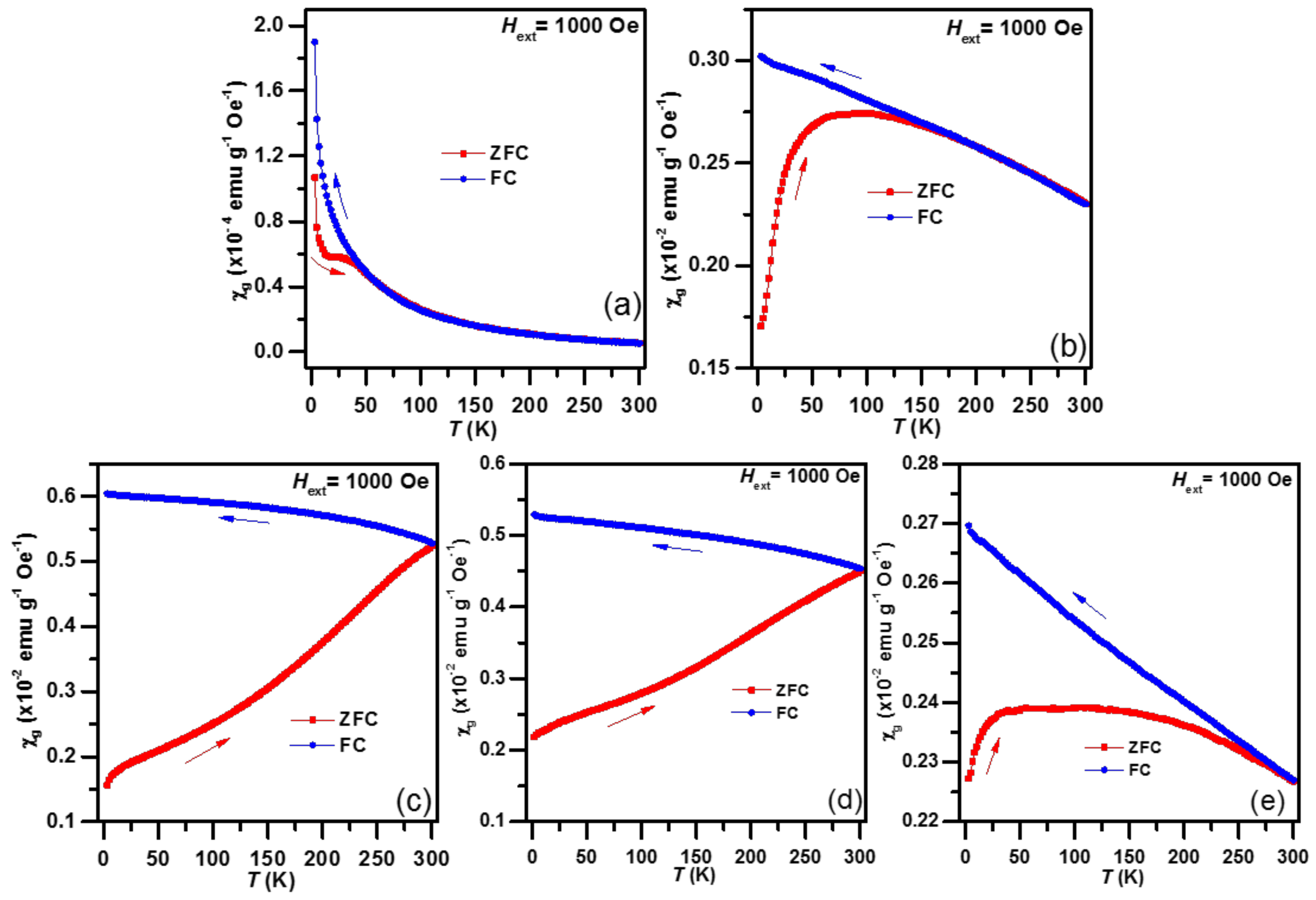
3.3. Magnetization and Magnetic Susceptibility

The magnetic properties of the CP and the NHD samples are, to a large extent, exposed through the behavior of their M vs. H under constant temperature (T), as well as their χg vs. T under constant H measurements, which are exhibited for all samples in Figure 5 and Figure 6, respectively. The isothermal M vs. H loops were collected at RT (300 K) and 5 K, while the χg vs. T scans were performed in ZFC and FC modes under H = 1000 Oe.
Starting the description from the CP sample, the M vs. H loop at RT in Figure 5a shows linear paramagnetic-like behavior, while a ferromagnetic/ferrimagnetic sigmoidal-type curve with non-saturated M values and non-vanishing and asymmetric coercive fields (HCs) is developed at 5 K. The maximum M values at 50 kOe (Mmax), along with all other characteristics of the loops for all samples, are listed in Table 2. The corresponding χg vs. T ZFC curve begins with a maximum at 5 K and continues with a local maximum at ~25 K, followed by a monotonic decrease for higher T values, while the FC curve exhibits a monotonic increase throughout the whole T range with an asymptotic behavior at low T. The bifurcation of the two curves occurs at the irreversibility temperature of Tirr ~60 K. The previously described characteristics are indicative of an assembly of ferromagnetic/ferrimagnetic-type NPs that are completely superparamagnetic (SPM) at RT and partially magnetically blocked at low T [56]. The existence of two χg maxima at blocking temperatures of TB ~5 K and TB ~25 K for the ZFC curve, along with the Tirr-TB difference of about 35 K, indicate a dispersion of NP sizes, which however, due to the low TB values, seem to be quite small in magnitude, while the asymmetry in HC at 5 K denotes the presence of exchange-bias interactions between different types of magnetic ordered phases, that might result, e.g., due to possible variations in stoichiometry or/and a core-shell NPs structure [56]. Due to their extremely small sizes, the smaller NPs could take a more drastic shift in their spinel-type ferric oxide (maghemite) stoichiometry, mainly affecting their surface atomic layers, as well as a reduction in their crystallinity towards a more amorphous structure. These structural characteristics, accompanied by the magnetic interactions between interconnected NPs, could justify their observed magnetic properties that resemble spin-glass-like behavior at low temperatures [57,58,59,60], and explain the asymmetry found in the coercivity values of the hysteresis loop of this sample at 5 K. Moreover, the asymptotic behavior of the FC curve at low T reveals that these NPs are magnetically non- or very weakly-interacting, reflecting their spatial isolation on the surface of the corresponding NDs nanotemplates [51,61,62].
A TB of ~100K and a Tirr of ~190 K are observed from the χg vs. T ZFC and FC curves of the NHD-600 sample. The higher TB and Tirr-TB ≈ 90 K difference values, compared to the CP sample case, indicate a system of ferromagnetic/ferrimagnetic-type NPs with relatively larger average sizes and wider size dispersion compared to those in the CP. Indeed, the increased NP size of the NHD-600 sample affords clear ferromagnetic characteristics in the M vs. H loops; however, the non-vanishing dM/dH slope at high fields and the increased HC values at 5 K relative to those observed at 300 K, declare the presence of a part of the NP assembly that retains SPM characteristics. On the other side, the corresponding χg values in the FC curve is almost linearly related to the decrease in T, and do not follow an asymptotic behavior at low temperatures, which suggests that magnetic interparticle interactions, most probably of dipolar or exchange nature [61,63,64], must be present, a result that should be expected from the respective size growth of the corresponding IO NPs in the CP.
Ferromagnetic characteristics are observed also in the M vs. H loops of the NHD-750 sample; however, there is a slight tendency for lack of saturation in the of M values at high fields. Further, the inset in Figure 5c reveals that the variation of M around H = 0 is not smooth but rather complex, and seems to be composed of two contributions: one with magnetically harder characteristics that lends non-vanishing HC values to the loops and one with magnetically softer characteristics that are responsible for the sadden drop of the M values at H = 0. The χg values of the ZFC curve for this sample show a continuous increase with increasing T with no local extrema up to 300 K, while the FC curve is also continuous and smoother over a quite narrower χg values range. These results are indicative of a system of ferromagnetic NPs with combined hard and soft magnetic characteristics that could result from size dispersion or/and magnetic interparticle interactions strength variation. Moreover, the behavior of the system seems to be dominated from the larger in size or/and strongly magnetically interacting NPs, which are magnetically blocked even at RT. On the other hand, the smaller in size or/and weakly magnetically interacting NPs reveal their presence through their softer magnetic characteristics and their non-saturation M values tendency. Thus, as Fe3C NPs with both multi-domain or single-domain characteristics can exist simultaneously in the sample, they can contribute different properties to the magnetic measurements, i.e., both strong (multi-domain) and soft (single-domain) ferromagnetic features, decisively influencing the magnetic characteristics of the system [43,56,65].
For the NHD-900 sample, very similar characteristics to the χg vs. T curves of the NHD-750 sample are observed, while its M vs. H loops are more saturated at high H and quite smooth around H = 0, with clear symmetric hystereses that reach HC values of the order of ~0.5 kOe at 300 K and 2.5 kOe at 5 K (see Table 2 and inset of Figure 5d). These results show that here, the system of ferromagnetic NPs seems to acquire on average larger sizes or/and experience stronger magnetic interparticle interactions. The NPs size and morphology in this sample involving the presence of larger elongated cementite NPs entering the interior or filling the ends of the CNTs and/or caught on their walls, should indeed induce an effect on the increased HC values. Similar behavior of high HC values has been found for elongated cementite NPs encapsulated by CNTs [66,67], where also the NPs size dispersion has been proposed to be a crucial factor for the appearance of this characteristic.
The M vs. H loops of the NHD-1050 sample are completely saturated at high H and symmetric around H = 0, showing hystereses with reduced HC values relative to those found for the NHD-900 sample (see Table 2). The χg values of the ZFC curve increase up to ~30 K and stay almost constant in a wide T range up to ~150 K, before dropping further smoothly up to 300 K, while for the FC branch χg increases almost linearly with the decrease in T. These characteristics reflect a system of ferromagnetic NPs with wide size dispersion and possible compositional variations, in which, however, the larger in size NPs are shaping the system’s magnetic behavior.

3.4. 57Fe Mössbauer Spectroscopy

The iron-containing phases present in the samples, their crystal structure, particle size and morphology, as well as their magnetic properties are further investigated by means of the atomic-level-probing technique of 57Fe Mössbauer spectroscopy. 57Fe MS of the studied samples recorded at RT (300 K) and 77 K appear in Figure 7. Some corresponding MS collected at lower temperature (11 K) are shown in SM (Figures S10 and S11).
The 300 K spectrum of the CP sample in Figure 7a exhibits only a central quadrupole split contribution, while development of partial magnetic splitting appears at the spectrum of this sample at 77 K in the form of broad magnetically split contributions, in addition to the main quadrupole split contribution that still dominates this spectrum. In order to fit these MS adequately, we used a single quadrupole split doublet with Lorentzian line-shapes for the RT spectrum and a combination of a quadrupole split doublet and two magnetically split components, for which a Gaussian-type spreading of their hyperfine magnetic field (Bhf) values (ΔBhf) [52] was allowed to model their broadening. The resulting Mössbauer parameters values for the RT spectra of all samples are listed in Table 3, while, for the lower temperature MS, the corresponding parameters are listed in SM (Tables S2 and S3). The IS, quadrupole splitting (QS), quadrupole shift (2ε) and Bhf values of all components of the CP sample correspond to Fe3+ ions in magnetically ordered γ-Fe2O3 NPs, which, due to their reduced size and influence of thermal agitation to their magnetization, undergo fast SPM relaxation, confirming the XRD, TEM and magnetization measurements [43,51,68,69,70].
The characteristic SPM relaxation time, τ, depends on the structural, morphological and magnetic characteristics of these NPs, through the magnetic anisotropy constant K, the size (or volume V) of the NPs, the presence and the strength of magnetic inter-particle interactions and the temperature [43,56,64,71,72]. Thanks to their very small size and good dispersion on the surfaces of the NDs nanotemplates, the IO NPs of the CP are relatively isolated, with loose inter-attachment or inter-connection to each other and experience no, or weak, inter-particle magnetic interactions, so they are not magnetically blocked at 300 K. For all these NPs represented by the SPM doublet at RT, the SPM relaxation is very fast, meaning that under these conditions (increased T), τ falls far below the characteristic 57Fe Mössbauer spectroscopy measuring time τMS-exp (τ < τMS-exp), which is of the order of τMS-exp ~10−8 s [73,74]. As a consequence, for these IO NPs the Bhf values at RT average to zero (they collapse completely).
By lowering the temperature to 77 K, the appearance of a minority, in absorption area (AA), set of broad magnetically split contributions indicates that a small part of the assembly of these IO NPs develops non-zero Bhf values. The existence of two different magnetically split components, one that acquires magnetically collapsing (MCOL) Bhf characteristics (Figure 7a 77 K wine color, SM Table S1 MCOL γ-Fe2O3 component) and another that presents broad lines but magnetically resolved (MRES) characteristics (Figure 7a 77 K light gray color, SM Table S1 MRES γ-Fe2O3 component), suggests that the assembly of these IO NPs in the CP sample can be described by the different aspects of the SPM relaxation. These aspects refer to the size of the NPs and their interactions through their inter-connection, which both influence τ as T is reduced from 300 to 77 K.
The assembly of the IO NPs of the CP can be viewed to be composed of three groups: The IO NPs, which are larger in size or/and better inter-connected to each other (or assembled together), have increased V or/and are experiencing stronger inter-particle magnetic interactions, acquire τ > τMS-exp at 77 K and are represented by the MRES Fe3+ component. The IO NPs, which are intermediate in size or/and less inter-connected, have relatively decreased V or/and are experiencing weaker inter-particle magnetic interactions, acquire τ ~τMS-exp at 77 K and are represented by the MCOL Fe3+ component. However, still at 77 K the majority of the IO NPs are completely SPM as they acquire τ < τMS-exp and are represented by the SPM doublet (Figure 7a 77 K orange color, SM Table S1 SPM γ-Fe2O3 component). This further confirms the picture drawn from all characterization methods used here for the CP, that presents an assembly of very small maghemite NPs relatively isolated on the surfaces of the NDs nanotemplates, which shows fast SPM relaxation at RT, but which is partially getting slower at lower temperatures.
The MS of the NHD-600 sample presents a combination of quadrupole and magnetically split contributions both at RT and 77 K, with the magnetically split part increasing its AA as the temperature decreases. For the RT spectrum, we used a set of one quadrupole and four magnetically split components and their resulting Mössbauer parameters are listed in Table 3. The doublet presents very similar parameters to the corresponding doublet of the CP, while there are two well resolved magnetically split components, one of which presents Fe3+ and the other Fe2.5+ valence state characteristics, which lie quite close to those of the corresponding ions of magnetite (Fe3O4) [75]. However, the ratio of their relative AA values, AA(Fe3+)/AA(Fe2.5+) = 1.4 is quite different from the nominal 0.5 expected for Fe3O4, indicating that the corresponding stoichiometry is shifted to non-stoichiometric Fe3−xO4 (0 < x < 0.33). For the other two magnetically split components, one presents broad and asymmetric lines, high Bhf value, increased IS relative to that of the SPM doublet and closer to the average of the Fe3+ and Fe2.5+ components, and the other broad and symmetric lines, low Bhf value and similar IS relative to that of the SPM doublet. Combining these results with the XRD, TEM and magnetization measurements and analyses, it is evident that this sample contains an assembly of spinel-type IO NPs dispersed on the surfaces of the NDs nanotemplates. The stoichiometry of these spinel-type IO NPs varies, most probably according to their sizes. The larger NPs have Fe3-xO4 stoichiometries (intermediate between maghemite x = 0.33 and magnetite x = 0), while the smaller NPs are of the maghemite type. A similar set of components is used to fit the 77 K spectrum of this sample, with the magnetic components increasing their AAs in total relative to those at RT at the expense of the AA of the SPM doublet. However, the presence of the Fe2.5+ component is not detected directly at 77 K, due to its low contribution, as evidenced from the RT spectrum, which is additionally screened by the major contribution of the broad asymmetric magnetically resolved component (see also SM).
The spectra of the NHD-750 sample appearing in Figure 7c show a clear dominant six-line pattern contribution with relative narrow resonant lines, in superposition to a central broad magnetically split part. This central broad part is more intense at RT and less at 77 K. In addition, an asymmetry (referring to the shape difference between the lower and higher absolute velocity sides) of the resonant lines for the clear magnetically resolved part is observed at RT, which is, however, reduced substantially at 77 K. In order to describe these characteristics, we used a set of six components to fit the RT spectrum. Four of them (colored with green tints) describe the cementite Fe3C phase, one minor component (colored magenta) acquires IS value corresponding to SPM metallic iron, and one quadrupole split component (colored orange) to an SPM IO phase of Fe3+ character. Of the four components describing the Fe3C phase, two of them have Mössbauer parameters values that are quite close to those of the bulk Fe3C phase [16,27]. The other two acquire IS and 2ε values that fall on the average of the two “bulk-like” components, while their Bhf values are reduced compared to the “bulk-like” components, slightly for one of them, which retains clear magnetically resolved characteristics (MRES Fe3C), and substantially for the other, which receives Bhf collapsing characteristics (MCOL Fe3C). These featuress reveal a system of Fe3C NPs that experience different types of SPM relaxation effects, similar to the case of the NHD-600 sample: the larger in size and more inter-connected Fe3C NPs acquire “bulk-like” characteristics with slow SPM relaxation, while the smaller and more isolated ones experience faster SPM relaxation at RT. However, in the case of the Fe3C phase there is no complete collapse of the Bhf value, which is attributed both to the larger size of the NPs and to the increased K value of Fe3C compared to those of the spinel-type IO NPs of the NHD-600 sample [67,76]. The thermal development of the shape of the MS from RT to 77 and 11 K is the expected one for an assembly of NPs which undergo SPM relaxation phenomena: the MRES component is absent at low temperatures, being merged with the “bulk-like” components, while the AA values of the MCOL component are constant at about 20%. This means that a fraction of the Fe3C NPs is still under the influence of SPM relaxation at temperatures as low as 11 K.
Taking into account the nature of the other two remaining minor components which were used to fit the MS of this sample and the fact that there are no additional diffraction peaks detected at the corresponding XRD diagram apart from those of the Fe3C and NDs phases, it is revealed that these components are related to iron-containing phases with SPM characteristics and very small particle sizes. The SPM component with the IS corresponding to a metallic iron phase, acquires zero Bhf values at all temperatures, but non-zero QS values as well. According to our fitting model, this component is attributed to a very small amount of metallic iron, which forms very fine NPs, most probably below ~5 nm. In such small sizes, these fine iron NPs have been found to lose their crystallinity and adopt amorphous structure characteristics, which is reflected as shifts in their hyperfine Mössbauer parameters values [77,78]. Moreover, the most probable presence of C atoms that might have diffused in the structure of these NPs could heighten further these shifts. The SPM IO doublet with the Fe3+ characteristics at the RT spectrum develops magnetic splitting with broad resonant lines at lower temperatures. This phase could be related to a minority of IO NPs developed during the annealing procedure, or to surface oxide layers related to the metallic iron NPs. The contributions of these two components sum up to AA levels of the order of ~5%.
Very similar MS to the NHD-750 sample are found also for the NHD-900 sample, which are shown in Figure 7d. The evolution of these spectra with respect to the decrease in temperature is also very similar to that found for the NHD-750 sample. Consequently, we have applied a fitting model which includes the same set of components that we used to fit the MS of the NHD-750 sample in order to fit the MS of the NHD-900 sample, and the resulting Mössbauer parameters for the later sample are almost identical to those resulting for the former (see Table 3 and SM Tables S2 and S3). The main difference between the two cases appears for the AA values of the “bulk-like” and MCOL Fe3C components at low temperatures. The AA values of the MCOL Fe3C component are reduced for the NHD-900 sample relative to the NHD-750 sample and the gain from this reduction for the NHD-900 sample is directed towards its “bulk-like” components, suggesting an increase in the relative population for the larger in size Fe3C NPs of the corresponding assembly. These results come in perfect agreement with the XRD, TEM and SQUID measurements of both samples.
The MS of the NHD-1050 sample synthesized at the highest annealing temperature, appearing in Figure 7e, resemble those of the samples annealed at 900 and 750 °C, but an additional contribution at the inner (lower absolute velocity sides) parts of the magnetically split pattern persists both at 300 and 77 K. Combining this feature with the evidence for the presence of the Fe5C2 phase confirmed by XRD, led us to include a sub-set of three additional components (colored with blue tints) to the fitting model we used to fit the MS of the NHD-750 and NHD-900 samples, in order to fit the MS of this sample. These components correspond to the Fe5C2 IC phase. The resulting Mössbauer parameters for these components are very close to those reported for the bulk Fe5C2 phase in the literature [27,79,80]. The presence of a central magnetically collapsing component is related to the Fe3C NPs assembly, as evidenced by its Mössbauer parameters values. Another broad magnetically split contribution of Fe3+ character and collapsing Bhf characteristics is attributed to an IO phase with SPM features. A Bhf-collapsed SPM component with small AA is also included in the fitting model, as in the cases of the NHD-750 and NHD-900 samples. However, here the IS of this component is shifted to values characteristic of the IC phases rather than metallic iron. Again, these results come in perfect agreement with the XRD, TEM and SQUID measurements for this sample.

4. Discussion

Summarizing the experimental data from all characterization methods used to study the NHD samples presented here, we can describe the evolution of the development of the different phases, as well as their properties in these NHDs, as a function of the syntheses conditions.
The CP itself constitutes a hybrid nanomaterial, composed of very fine γ-Fe2O3 NPs dispersed evenly on the surfaces of the ND nanotemplates, providing it with SPM characteristics. The effect of annealing these pristine NHDs under vacuum at relatively low temperatures (600 °C) is to increase the particle size of the maghemite NPs, and simultaneously, to partially reduce some of the Fe3+ ions to Fe2+. Wherever this valence reduction occurs, it alters the local environment of the iron ions, shifting the spinel-type structure and composition from maghemite (γ-Fe2O3 = Fe8/3O4 = Fe2.67O4) towards non-stoichiometric magnetite (Fe3−xO4, 0 < x < 0.33), as the heating under vacuum conditions represents a soft-reduction agent. The resulting material acquires ferrimagnetic characteristics due to the development of the spinel-type ferrimagnetic IO phases.
Increasing the annealing temperature to 750 °C triggers the involvement of a harder reduction agent present in the pristine NHDs to the synthesis mechanism of the final product. This agent is no other than the C atoms of the surface layers of the NDs nanotemplates assemblies, which are also known to exist partially in the form of graphitic-type coatings [38,81,82]. These C atoms not only provide the conditions for the full reduction of the CP’s Fe3+ ions to Fe0 character, but are able to enter the structure of the resulting NPs in the material, forming thus the cementite Fe3C phase. It seems that the synthesis procedure of the Fe3C phase under these conditions is almost complete, as the majority of the γ-Fe2O3 NPs of the CP are transformed to cementite, following the original pattern established by their presence as ancestors in the CP. However, a very small minority of them remains as γ-Fe2O3 NPs, or as surface layers of a small part in the sample comprised of metallic iron NPs which were reduced from the γ-Fe2O3 NPs without adopting the C atoms in their structure, or at least not to the level of forming the complete carbide phase. Due to the presence of the Fe3C phase, the resulting NHD material acquires ferromagnetic features, combining hard and soft magnetic phases which are attributed to the dispersion of size of the individual cementite NPs, as well as the different interconnection characteristics of their assemblies.
By altering further the annealing temperature to 900 °C, the effect of the annealing conditions, apart from the formation of the cementite NPs phase in the resulting NHDs, is to lead some part of the C atoms of the CP to become involved in the growth of large-sized CNTs. The presence of the cementite phase itself at this annealing temperature plays the most important role in this CNTs growth procedure: it acts as the catalyst that is activated due to the increased temperature of 900 °C, compared to the lower annealing temperature of 750 °C where the production of CNTs could not be triggered [83]. The Fe3C NPs acquire, as expected, on average larger sizes than those developed at the lower annealing temperature of 750 °C. On the other hand, the cementite phase that is involved in the CNTs growth seems to enter partially their interior, forming larger elongated sections covering their ends, or being caught as smaller NPs within their walls. The increased sizes, as well as the elongated schemes of these Fe3C NPs, provide hard ferromagnetic characteristics to the resulting NHD material, with HC values reaching ~2.5 kOe at 5 K.
Impelling the CP system to more elevated annealing temperatures of the 1050 °C level, stimulates further the size increase in the Fe3C NPs, the production of the additional IC Fe5C2 phase, as well as the further growth of CNTs, both in concentration and in size. The IC phases are not only involved in the growth of CNTs, but are frequently included as moieties in their interiors or are encapsulated by them. Simultaneously, some IC NPs retain the dispersion form provided by their γ-Fe2O3 NPs ancestors in the CP and remain at the surfaces of the NDs nanotemplates. The magnetic properties of the resulting NHD material is influenced by the wider dispersion of NPs sizes, morphology and stoichiometry, but is governed by the larger IC NPs that provide hard ferromagnetic characteristics, albeit with reduced HC values relative to the sample annealed at 900 °C, most probably due to the multi-domain character of the NPs induced by their size growth.

5. Conclusions

In the present work, a versatile synthesis technique of magnetic nanostructured hybrid materials focused on iron carbides is deployed. A chemical precursor composed of fine maghemite nanoparticles dispersed on the surfaces of nanodiamond nanotemplates was used as the starting material. We have proven that by treating the chemical precursor in evacuated quartz ampules under different annealing conditions we can control and tailor the production of a variety of different nanostructured phases present in the nanohybrids, from spinel-type iron oxides, to iron carbides of Fe3C and Fe5C2 stoichiometries, as well as large-size carbon nanotubes. The magnetic properties of the resulting hybrid nanomaterials reflect the characteristics of their bearing magnetic phases, which span from superparamagnetic to soft and hard ferromagnetic. It is demonstrated that a hybrid nanomaterial composed of single phase ~10 nm Fe3C nanoparticles dispersed evenly on the surface of nanodiamond nanotemplates can be produced, which could be suitable for important technological applications in the fields of nano-biomedicine and catalysis.
Further development and adjustment of the present proposed synthetic route provides a good prospect for the development of a new category of magnetic nanohybrid materials based on nanodiamonds.

Supplementary Materials

The following are available online at https://www.mdpi.com/2312-7481/6/4/73/s1, Figure S1. TEM images of the CP sample. Figure S2. TEM images of the NHD-600 sample. Figure S3. TEM images of the NHD-750 sample. Figure S4. TEM images of the NHD-900 sample. Figure S5. TEM images of the NHD-1050 sample. Figure S6. HAADF image from a certain nanotemplate cluster of the NHD-750 sample with specific elemental mapping. Figure S7. HAADF image from a certain nanotemplate cluster of the NHD-900 sample with specific elemental mapping. Figure S8. HAADF image from a certain portion of the NHD-900 sample including NDs nanotemplates and CNTs with specific elemental mapping. Figure S9. HAADF image from a certain portion of the NHD-900 sample including NDs nanotemplates and CNTs with specific elemental mapping. Figure S10. Mössbauer spectrum of the NHD-750 sample recorded at 11K. Figure S11. Mössbauer spectrum of the NHD-900 sample recorded at 11 K. Table S1. Mössbauer Parameters as resulting from the best fits of the MS of all samples recorded at 77 K. Table S2. Mössbauer Parameters as resulting from the best fits of the MS of the NHD-750 and NHD-900 samples recorded at 11 K.

Author Contributions

Conceptualization, A.P.D.; Data curation, P.Z., A.B.B., J.T., O.M. and A.P.D.; Formal analysis, P.Z., A.B.B., J.T., O.M. and A.P.D.; Investigation, P.Z., A.B.B., J.T., O.M. and A.P.D.; Methodology, P.Z., A.B.B. and A.P.D.; Software, P.Z. and A.P.D.; Supervision, A.P.D.; Writing—original draft, P.Z. and A.P.D.; Writing—review and editing, P.Z., A.B.B. and A.P.D. All authors have read and agreed to the published version of the manuscript.

Funding

This research received no external funding.

Acknowledgments

A.P.D. acknowledges the partial support of this work by the project MIS 5002772, implemented under the Action “Reinforcement of the Research and Innovation Infrastructure”, funded by the Operational Programme “Competitiveness, Entrepreneurship and Innovation” (NSRF 2014–2020) and co-financed by Greece and the European Union (European Regional Development Fund). O.M. acknowledges the financial support from the ERDF/ESF “Nano4Future” grant (No. CZ.02.1.01/0.0/0.0/16_019/0000754).

Conflicts of Interest

The authors declare no conflict of interest.

Abbreviations/Acronyms

quadrupole shift
Bhfhyperfine magnetic field
CNT(s)carbon nanotube (s)
CPchemical precursor
FCfield-cooled
Happlied magnetic field
HAADFhigh-angle annular dark field
HC(s)coercive field (s)
IC(s)iron carbide (s)
IO(s)iron oxide (s)
ISisomer shift
Kmagnetic anisotropy constant
Mmagnetization
MCOLmagnetically collapsing
Mmaxmaximum M value at 50 kOe
MPImagnetic particle imaging
MRremnant magnetization
MRESmagnetically resolved
MRImagnetic resonance imaging
MSsaturation magnetization
MSMössbauer spectra
ND(s)Nanodiamond (s)
NP(s)nanoparticle(s)
QSquadrupole splitting
RTroom temperature
SMSupplementary Material
SPMsuperparamagnetic
SQUIDsuperconducting quantum interference device
Ttemperature
TEMtransmission electron microscopy
Vvolume
vsversus
XRDX-ray diffraction
ZFCzero-field-cooled
ΔBhfspreading of hyperfine magnetic field
τMS-expcharacteristic 57Fe Mössbauer spectroscopy measuring time
τrelaxation time
χgmass magnetic susceptibility

References

  1. Giordano, C.; Kraupner, A.; Wimbush, S.C.; Antonietti, M. Iron carbide: An ancient advanced material. Small 2010, 6, 1859–1862. [Google Scholar] [CrossRef] [PubMed]
  2. Ye, Z.; Zhang, P.; Lei, X.; Wang, X.; Zhao, N.; Yang, H. Iron Carbides and Nitrides: Ancient Materials with Novel Prospects. Chem. A Eur. J. 2018, 24, 8922–8940. [Google Scholar] [CrossRef] [PubMed]
  3. Bhadeshia, H.K.D.H. Cementite. Int. Mater. Rev. 2020, 65, 1–27. [Google Scholar] [CrossRef] [Green Version]
  4. Weng, Y.; Dong, H.; Yong, G. Advanced Steels; Weng, Y., Dong, H., Yong, G., Eds.; Springer: Berlin/Heidelberg, Germany; Dordrecht, The Netherlands; London, UK; New York, NY, USA, 2011. [Google Scholar] [CrossRef]
  5. Hosford, W.F. Iron and Steel; Cambridge University Press: Cambridge, UK, 2012. [Google Scholar]
  6. Han, K.; Edmonds, D.V.; Smith, G.D.W. Optimization of mechanical properties of high-carbon pearlitic steels with Si and V additions. Metall. Mater. Trans. A 2001, 32, 1313–1324. [Google Scholar] [CrossRef] [Green Version]
  7. Han, K.; Chen, J.P. Achievable Strength of Nanostructured Composites with Co-Deformable Components. Mater. Sci. Forum 2011, 683, 243–247. [Google Scholar] [CrossRef]
  8. Li, L.; Virta, J. Ultrahigh strength steel wires processed by severe plastic deformation for ultrafine grained microstructure. Mater. Sci. Technol. 2011, 27, 845–862. [Google Scholar] [CrossRef]
  9. Elwazri, A.M.; Wanjara, P.; Yue, S. The effect of microstructural characteristics of pearlite on the mechanical properties of hypereutectoid steel. Mater. Sci. Eng. A 2005, 404, 91–98. [Google Scholar] [CrossRef]
  10. De Smit, E.; Cinquini, F.; Beale, A.M.; Safonova, O.V.; van Beek, W.; Sautet, P.; Weckhuysen, B.M. Stability and Reactivity of ϵ−χ−θ Iron Carbide Catalyst Phases in Fischer−Tropsch Synthesis: Controlling μC. J. Am. Chem. Soc. 2010, 132, 14928–14941. [Google Scholar] [CrossRef]
  11. Xu, K.; Sun, B.; Lin, J.; Wen, W.; Pei, Y.; Yan, S.; Qiao, M.; Zhang, X.; Zong, B. ε-Iron carbide as a low-temperature Fischer–Tropsch synthesis catalyst. Nature Commun. 2014, 5, 5783. [Google Scholar] [CrossRef]
  12. Niemantsverdriet, J.W.; van der Kraan, A.M.; van Dijk, W.L.; van der Baan, H.S. Behavior of metallic iron catalysts during Fischer-Tropsch synthesis studied with Mössbauer spectroscopy, x-ray diffraction, carbon content determination, and reaction kinetic measurements. J. Phys. Chem. 1980, 84, 3363–3370. [Google Scholar] [CrossRef]
  13. Yoshida, H.; Takeda, S.; Uchiyama, T.; Kohno, H.; Homma, Y. Atomic-Scale In-situ Observation of Carbon Nanotube Growth from Solid State Iron Carbide Nanoparticles. Nano Lett. 2008, 8, 2082–2086. [Google Scholar] [CrossRef] [PubMed]
  14. Schaper, A.K.; Hou, H.; Greiner, A.; Phillipp, F. The role of iron carbide in multiwalled carbon nanotube growth. J. Catal. 2004, 222, 250–254. [Google Scholar] [CrossRef]
  15. Pérez-Cabero, M.; Taboada, J.B.; Guerrero-Ruiz, A.; Overweg, A.R.; Rodríguez-Ramos, I. The role of alpha-iron and cementite phases in the growing mechanism of carbon nanotubes: A 57Fe Mössbauer spectroscopy study. Phys. Chem. Chem. Phys. 2006, 8, 1230–1235. [Google Scholar] [CrossRef] [PubMed]
  16. Le Caer, G.; Dubois, J.M.; Pijolat, M.; Perrichon, V.; Bussiere, P. Characterization by Moessbauer spectroscopy of iron carbides formed by Fischer-Tropsch synthesis. J. Phys. Chem. 1982, 86, 4799–4808. [Google Scholar] [CrossRef]
  17. Abel, F.M.; Pourmiri, S.; Basina, G.; Tzitzios, V.; Devlin, E.; Hadjipanayis, G.C. Iron carbide nanoplatelets: Colloidal synthesis and characterization. Nanoscale Adv. 2019, 1, 4476–4480. [Google Scholar] [CrossRef] [Green Version]
  18. Lin, J.-F.; Struzhkin, V.V.; Mao, H.-k.; Hemley, R.J.; Chow, P.; Hu, M.Y.; Li, J. Magnetic transition in compressed Fe3C from X-ray emission spectroscopy. Phys. Rev. B 2004, 70, 212405. [Google Scholar] [CrossRef] [Green Version]
  19. Zhao, X.Q.; Liang, Y.; Hu, Z.Q.; Liu, B.X. Oxidation characteristics and magnetic properties of iron carbide and iron ultrafine particles. J. Appl. Phys. 1996, 80, 5857–5860. [Google Scholar] [CrossRef]
  20. Schnepp, Z.; Wimbush, S.C.; Antonietti, M.; Giordano, C. Synthesis of Highly Magnetic Iron Carbide Nanoparticles via a Biopolymer Route. Chem. Mater. 2010, 22, 5340–5344. [Google Scholar] [CrossRef]
  21. Huang, G.; Hu, J.; Zhang, H.; Zhou, Z.; Chi, X.; Gao, J. Highly magnetic iron carbide nanoparticles as effective T2 contrast agents. Nanoscale 2014, 6, 726–730. [Google Scholar] [CrossRef]
  22. Liang, Y.; Liu, P.; Xiao, J.; Li, H.; Wang, C.; Yang, G. A microfibre assembly of an iron-carbon composite with giant magnetisation. Sci. Rep. 2013, 3, 3051. [Google Scholar] [CrossRef]
  23. Gao, S.; Yang, S.-H.; Wang, H.-Y.; Wang, G.-S.; Yin, P.-G. Excellent electromagnetic wave absorbing properties of two-dimensional carbon-based nanocomposite supported by transition metal carbides Fe3C. Carbon 2020, 162, 438–444. [Google Scholar] [CrossRef]
  24. Bordet, A.; Lacroix, L.-M.; Fazzini, P.-F.; Carrey, J.; Soulantica, K.; Chaudret, B. Magnetically Induced Continuous CO2 Hydrogenation Using Composite Iron Carbide Nanoparticles of Exceptionally High Heating Power. Angew. Chem. Int. Ed. 2016, 55, 15894–15898. [Google Scholar] [CrossRef] [PubMed]
  25. Kale, S.S.; Asensio, J.M.; Estrader, M.; Werner, M.; Bordet, A.; Yi, D.; Marbaix, J.; Fazzini, P.-F.; Soulantica, K.; Chaudret, B. Iron carbide or iron carbide/cobalt nanoparticles for magnetically-induced CO2 hydrogenation over Ni/SiRAlOx catalysts. Catal. Sci. Technol. 2019, 9, 2601–2607. [Google Scholar] [CrossRef]
  26. Meffre, A.; Mehdaoui, B.; Kelsen, V.; Fazzini, P.F.; Carrey, J.; Lachaize, S.; Respaud, M.; Chaudret, B. A Simple Chemical Route toward Monodisperse Iron Carbide Nanoparticles Displaying Tunable Magnetic and Unprecedented Hyperthermia Properties. Nano Lett. 2012, 12, 4722–4728. [Google Scholar] [CrossRef] [PubMed]
  27. Liu, X.-W.; Zhao, S.; Meng, Y.; Peng, Q.; Dearden, A.K.; Huo, C.-F.; Yang, Y.; Li, Y.-W.; Wen, X.-D. Mössbauer Spectroscopy of Iron Carbides: From Prediction to Experimental Confirmation. Sci. Rep. 2016, 6, 26184. [Google Scholar] [CrossRef] [Green Version]
  28. Fang, C.M.; van Huis, M.A.; Zandbergen, H.W. Structure and stability of Fe2C phases from density-functional theory calculations. Scr. Mater. 2010, 63, 418–421. [Google Scholar] [CrossRef]
  29. Elsukov, E.P.; Dorofeev, G.A.; Ul’yanov, A.L.; Vytovtov, D.A. On the problem of the cementite structure. Phys. Metals Metallogr. 2006, 102, 76–82. [Google Scholar] [CrossRef]
  30. Ron, M.; Mathalone, Z. Hyperfine Interactions of 57Fe in Fe3C. Phys. Rev. B 1971, 4, 774–777. [Google Scholar] [CrossRef]
  31. Li, S.; Yang, J.; Song, C.; Zhu, Q.; Xiao, D.; Ma, D. Iron Carbides: Control Synthesis and Catalytic Applications in COx Hydrogenation and Electrochemical HER. Adv. Mater. 2019, 31, 1901796. [Google Scholar] [CrossRef]
  32. Sajitha, E.P.; Prasad, V.; Subramanyam, S.V.; Mishra, A.K.; Sarkar, S.; Bansal, C. Size-dependent magnetic properties of iron carbide nanoparticles embedded in a carbon matrix. J. Phys. Condens. Matter 2007, 19, 046214. [Google Scholar] [CrossRef]
  33. Schneeweiss, O.; Zbořil, R.; David, B.; Heřmánek, M.; Mashlan, M. Solid-State Synthesis of α-Fe and Iron Carbide Nanoparticles by Thermal Treatment of Amorphous Fe2O3; Springer: Berlin/Heidelberg, Germany, 2009; pp. 167–173. [Google Scholar]
  34. Lin, S.C.; Phillips, J. Study of relaxation effects in the 57Fe Mössbauer spectra of carbon-supported iron carbide particles. J. Appl. Phys. 1985, 58, 1943–1949. [Google Scholar] [CrossRef]
  35. Lipert, K.; Kazmierczak, J.; Pelech, I.; Narkiewicz, U.; Slawska-Waniewska, A.; Lachowicz, H.K. Magnetic properties of cementite (Fe3C) nanoparticle agglomerates in a carbon matrix. Mater. Sci. Pol. 2007, 25, 2. [Google Scholar]
  36. Pierson, H.O. Handbook of Carbon, Graphite, Diamond And Fullerenes: Properties, Processing and Applications; Noyes Publications: Park Ridge, NJ, USA, 1993. [Google Scholar]
  37. Shenderova, O.A.; Gruen, D.M. Ultrananocrystalline Diamond: Synthesis, Properties and Applications, 2nd ed.; Elsevier: Oxford, UK, 2012; pp. 1–558. [Google Scholar]
  38. Vul’, A.; Shenderova, O. Detonation Nanodiamonds: Science and Applications; CRC Press: Boca Raton, FL, USA, 2013. [Google Scholar]
  39. Mochalin, V.N.; Shenderova, O.; Ho, D.; Gogotsi, Y. The properties and applications of nanodiamonds. Nat. Nanotechnol. 2011, 7, 11–23. [Google Scholar] [CrossRef] [PubMed]
  40. Bourlinos, A.B.; Zbořil, R.; Kubala, M.; Stathi, P.; Deligiannakis, Y.; Karakassides, M.A.; Steriotis, T.A.; Stubos, A.K. Fabrication of fluorescent nanodiamond@C core-shell hybrids via mild carbonization of sodium cholate-nanodiamond complexes. J. Mater. Sci. 2011, 46, 7912–7916. [Google Scholar] [CrossRef]
  41. Ho, D. Nanodiamonds: Applications in Biology and Nanoscale Medicine; Springer: New York, NY, USA, 2010. [Google Scholar]
  42. Chen, M.; Pierstorff, E.D.; Lam, R.; Li, S.Y.; Huang, H.; Osawa, E.; Ho, D. Nanodiamond-mediated delivery of water-insoluble therapeutics. ACS Nano 2009, 3, 2016–2022. [Google Scholar] [CrossRef]
  43. Douvalis, A.P.; Bourlinos, A.B.; Tucek, J.; Čépe, K.; Bakas, T.; Zboril, R. Development of novel FePt/nanodiamond hybrid nanostructures: L10 phase size-growth suppression and magnetic properties. J. Nanopart. Res. 2016, 18, 115. [Google Scholar] [CrossRef]
  44. Laurent, S.; Henoumont, C.; Stanicki, D.; Boutry, S.; Lipani, E.; Belaid, S.; Muller, R.N.; Vander Elst, R.N. MRI Contrast Agents: From Molecules to Particles; Springer: Berlin/Heidelberg, Germany, 2017. [Google Scholar] [CrossRef]
  45. Pierre, V.C.; Allen, M.J. Contrast Agents for MRI: Experimental Methods; The Royal Society of Chemistry: London, UK, 2018. [Google Scholar]
  46. Knopp, T.; Buzug, T.M. Magnetic Particle Imaging: An Introduction to Imaging Principles and Scanner Instrumentation; Springer: Berlin/Heidelberg, Germany, 2012. [Google Scholar]
  47. Erbe, M. Field Free Line Magnetic Particle Imaging; Springer: Berlin/Heidelberg, Germany, 2014. [Google Scholar]
  48. Deatsch, A.E.; Evans, B.A. Heating efficiency in magnetic nanoparticle hyperthermia. J. Magn. Magn. Mater. 2014, 354, 163–172. [Google Scholar] [CrossRef]
  49. Wang, W.; Tuci, G.; Duong-Viet, C.; Liu, Y.; Rossin, A.; Luconi, L.; Nhut, J.-M.; Nguyen-Dinh, L.; Pham-Huu, C.; Giambastiani, G. Induction Heating: An Enabling Technology for the Heat Management in Catalytic Processes. ACS Catal. 2019, 9, 7921–7935. [Google Scholar] [CrossRef]
  50. Bourlinos, A.; Simopoulos, A.; Petridis, D.; Okumura, H.; Hadjipanayis, G. Silica-Maghemite Nanocomposites. Adv. Mater. 2001, 13, 289–291. [Google Scholar] [CrossRef]
  51. Tsoufis, T.; Douvalis, A.P.; Lekka, C.E.; Trikalitis, P.N.; Bakas, T.; Gournis, D. Controlled preparation of carbon nanotube–iron oxide nanoparticle hybrid materials by a modified wet impregnation method. J. Nanopart. Res. 2013, 15, 1924–1927. [Google Scholar] [CrossRef]
  52. Douvalis, A.P.; Polymeros, A.; Bakas, T. IMSG09: A 57Fe-119Sn Mössbauer spectra computer fitting program with novel interactive user interface. J. Phys. Conf. Ser. 2010, 217, 012014. [Google Scholar] [CrossRef]
  53. Cornell, R.M.; Schwertmann, U. The Iron Oxides: Structure, Properties, Reactions, Occurrences and Uses; Wiley-VCH: Weinheim, Germany, 2003. [Google Scholar]
  54. Cullity, B.D.; Stock, S.R. Elements of X-Ray Diffraction, 3rd ed.; Pearson Education Limited: London, UK, 2014. [Google Scholar]
  55. Gournis, D.; Karakassides, M.A.; Bakas, T.; Boukos, N.; Petridis, D. Catalytic synthesis of carbon nanotubes on clay minerals. Carbon 2002, 40, 2641–2646. [Google Scholar] [CrossRef]
  56. Cullity, B.D.; Graham, C.D. Introduction to Magnetic Materials; John Wiley & Sons: Hoboken, NJ, USA, 2009. [Google Scholar]
  57. Khurshid, H.; Lampen-Kelley, P.; Iglesias, Ò.; Alonso, J.; Phan, M.-H.; Sun, C.-J.; Saboungi, M.-L.; Srikanth, H. Spin-glass-like freezing of inner and outer surface layers in hollow γ-Fe2O3 nanoparticles. Sci. Rep. 2015, 5, 15054. [Google Scholar] [CrossRef] [PubMed]
  58. Cabreira-Gomes, R.; Silva, F.G.; Aquino, R.; Bonville, P.; Tourinho, F.A.; Perzynski, R.; Depeyrot, J. Exchange bias of MnFe2O4@γFe2O3 and CoFe2O4@γFe2O3 core/shell nanoparticles. J. Magn. Magn. Mater. 2014, 368, 409–414. [Google Scholar] [CrossRef]
  59. Zhu, C.; Tian, Z.; Wang, L.; Yuan, S. Exchange bias effect in spin glass CoCr2O4 nanoparticles. J. Magn. Magn. Mater. 2015, 393, 116–120. [Google Scholar] [CrossRef]
  60. Giri, S.K.; Poddar, A.; Nath, T.K. Evidence of exchange bias effect and surface spin glass ordering in electron doped Sm0.09Ca0.91MnO3 nanomanganites. J. Appl. Phys. 2012, 112, 113903. [Google Scholar] [CrossRef]
  61. Fiorani, D. Surface Effects in Magnetic Nanoparticles; Springer: New York, NY, USA, 2005. [Google Scholar]
  62. Gubin, S.P. Magnetic Nanoparticles; Wiley-VCH: Weinheim, Germany, 2009. [Google Scholar]
  63. Kostopoulou, A.; Brintakis, K.; Vasilakaki, M.; Trohidou, K.N.; Douvalis, A.P.; Lascialfari, A.; Manna, L.; Lappas, A. Assembly-mediated interplay of dipolar interactions and surface spin disorder in colloidal maghemite nanoclusters. Nanoscale 2014, 6, 3764–3776. [Google Scholar] [CrossRef] [Green Version]
  64. Mørup, S.; Hansen, M. Superparamagnetic Particles. In Handbook of Magnetism and Advanced Magnetic Materials; Kronmüller, H., Parkin, S., Eds.; Novel Materials; John Wiley & Sons: Hoboken, NJ, USA, 2007; Volume 4. [Google Scholar]
  65. Li, Q.; Kartikowati, C.W.; Horie, S.; Ogi, T.; Iwaki, T.; Okuyama, K. Correlation between particle size/domain structure and magnetic properties of highly crystalline Fe3O4 nanoparticles. Sci. Rep. 2017, 7, 9894. [Google Scholar] [CrossRef]
  66. Morelos-Gómez, A.; López-Urías, F.; Muñoz-Sandoval, E.; Dennis, C.L.; Shull, R.D.; Terrones, H.; Terrones, M. Controlling high coercivities of ferromagnetic nanowires encapsulated in carbon nanotubes. J. Mater. Chem. 2010, 20, 5906–5914. [Google Scholar] [CrossRef]
  67. Liu, D.; Zhu, J.; Ivaturi, S.; He, Y.; Wang, S.; Wang, J.; Zhang, S.; Willis, M.A.C.; Boi, F.S. Giant magnetic coercivity in Fe3C-filled carbon nanotubes. RSC Adv. 2018, 8, 13820–13825. [Google Scholar] [CrossRef] [Green Version]
  68. Corr, S.A.; Gun’ko, Y.K.; Douvalis, A.P.; Venkatesan, M.; Gunning, R.D.; Nellist, P.D. From Nanocrystals to Nanorods: New Iron Oxide-Silica Nanocomposites from Metallorganic Precursors. J. Phys. Chem. C 2008, 112, 1008. [Google Scholar] [CrossRef]
  69. Biddlecombe, G.B.; Gun’ko, Y.K.; Kelly, J.M.; Pillai, S.C.; Coey, J.M.D.; Venkatesan, M.; Douvalis, A.P. Preparation of magnetic nanoparticles and their assemblies using a new Fe(ii) alkoxide precursor. J. Mater. Chem. 2001, 11, 2937–2939. [Google Scholar] [CrossRef]
  70. Tsoufis, T.; Tomou, A.; Gournis, D.; Douvalis, A.P.; Panagiotopoulos, I.; Kooi, B.; Georgakilas, V.; Arfaoui, I.; Bakas, T. Novel nanohybrids derived from the attachment of FePt nanoparticles on carbon nanotubes. J. Nanosci. Nanotechnol. 2008, 8, 5942–5951. [Google Scholar] [CrossRef] [PubMed]
  71. Mørup, S. Magnetic Hyperfine Splitting in Mössbauer Spectra of Microcrystals. J. Magn. Magn. Mater. 1983, 37, 39. [Google Scholar] [CrossRef]
  72. Mørup, S. Mössbauer Effect in Small Particles. Hyperfine Interact. 1990, 60, 959. [Google Scholar] [CrossRef]
  73. Greenwood, N.N.; Gibb, T.C. Mössbauer Spectroscopy; Chapman and Hall Ltd.: London, UK, 1971. [Google Scholar]
  74. Gutlich, P.; Bill, E.; Trautwein, A.X. Mo¨ssbauer Spectroscopy and Transition Metal Chemistry: Fundamentals and Applications; Springer: Berlin/Heidelberg, Germany, 2011. [Google Scholar] [CrossRef]
  75. Vandenberghe, R.E.; de Grave, E. Mossbauer Effect Studies of Oxidic Spinels. In Mössbauer Spectroscopy Applied to Inorganic Chemistry; Long, G.J., Grandjean, J., Eds.; Springer Science & Business Media, LLC: New York, NY, USA, 1989; Volume 3. [Google Scholar]
  76. Fardis, M.; Douvalis, A.P.; Tsitrouli, D.; Rabias, I.; Stamopoulos, D.; Kehagias, T.; Karakosta, E.; Diamantopoulos, G.; Bakas, T.; Papavassiliou, G. Structural, static and dynamic magnetic properties of dextran coated γ-Fe2O3nanoparticles studied by57Fe NMR, Mössbauer, TEM and magnetization measurements. J. Phys. Condens. Matter 2012, 24, 156001. [Google Scholar] [CrossRef]
  77. Long, G.J.; Hautot, D.; Pankhurst, Q.A.; Vandormael, D.; Grandjean, F.; Gaspard, J.P.; Briois, V.; Hyeon, T.; Suslick, K.S. M\"ossbauer-effect and x-ray-absorption spectral study of sonochemically prepared amorphous iron. Phys. Rev. B 1998, 57, 10716–10722. [Google Scholar] [CrossRef] [Green Version]
  78. Carroll, K.J.; Pitts, J.A.; Zhang, K.; Pradhan, A.K.; Carpenter, E.E. Nonclassical crystallization of amorphous iron nanoparticles by radio frequency methods. J. Appl. Phys. 2010, 107, 09A302. [Google Scholar] [CrossRef]
  79. Le Caer, G.; Dubois, J.M.; Senateur, J.P. Etude par spectrométrie Mössbauer des carbures de Fer Fe3C et Fe5C2. J. Solid State Chem. 1976, 19, 19–28. [Google Scholar] [CrossRef]
  80. Gatte, R.R.; Phillips, J. The influence of particle size and structure on the Mössbauer spectra of iron carbides formed during Fischer-Tropsch synthesis. J. Catal. 1987, 104, 365–374. [Google Scholar] [CrossRef]
  81. Williams, O.A. Nanocrystalline diamond. Diam. Relat. Mater. 2011, 20, 621–640. [Google Scholar] [CrossRef]
  82. Williams, O. Nanodiamond; Royal Society of Chemistry: Cambridge, UK, 2014. [Google Scholar]
  83. Mykhaylyk, O.O.; Solonin, Y.M.; Batchelder, D.N.; Brydson, R. Transformation of nanodiamond into carbon onions: A comparative study by high-resolution transmission electron microscopy, electron energy-loss spectroscopy, x-ray diffraction, small-angle x-ray scattering, and ultraviolet Raman spectroscopy. J. Appl. Phys. 2005, 97, 074302. [Google Scholar] [CrossRef]
Figure 1. Schematic representation of the synthesis stages followed and the resulting nanohybrid samples produced in this work.
Magnetochemistry 06 00073 g001
Figure 2. XRD patterns of the CP (a) and the NHDs samples resulting by annealing the CP at different temperatures indicated (in °C): 1050 (b), 900 (c), 750 (d) and 600 (e). The presence of the different crystalline phases in the samples is denoted by the relative symbols on their diffraction peaks.
Magnetochemistry 06 00073 g002
Figure 3. TEM images of the CP (ac), NHD-1050 (df), NHD-900 (gi), NHD-750 (jl) and NHD-600 (mo) samples at different magnifications.
Magnetochemistry 06 00073 g003
Figure 4. HAADF microscopy image from a certain nanotemplate cluster of the NHD-750 sample (a) with specific elemental mapping of C (b); Fe (c) and Fe & C (d).
Magnetochemistry 06 00073 g004
Figure 5. Isothermal M vs. H loops of the CP (a); NHD-600 (b); NHD-750 (c); NHD-900 (d) and NHD-1050 (e) samples collected at RT (red squares) and 5 K (blue circles). The insets show the detailed features of the loops around H = 0.
Magnetochemistry 06 00073 g005
Figure 6. χg vs. T measurements of the CP (a); NHD-600 (b); NHD-750 (c); NHD-900 (d) and NHD-1050 (e) samples collected under H = 1000 Oe following ZFC (red squares) and FC (blue circles) modes.
Magnetochemistry 06 00073 g006
Figure 7. 57Fe Mössbauer spectra of the CP (a); NHD-600 (b); NHD-750 (c); NHD-900 (d) and NHD-1050 (e) samples collected at 300 and 77 K.
Magnetochemistry 06 00073 g007
Table 1. Average NPs crystalline domain size <D> values, in nm, of the crystalline phases detected in the XRD diagrams of the samples as resulting using the Scherrer formula. The figures in parentheses denote the uncertainty attributed to the relevant last digit.
SampleNDsFe3CFe5C2Spinel-Type Iron OxideC-Graphitic
CP4 (1)--non-resolvable-
NHD-10507 (1)20 (1)16 (1)-11 (1)
NHD-9005 (1)16 (1)--8 (1)
NHD-7505 (1)12 (1)---
NHD-6004 (1)--9 (1)-
Table 2. Isothermal hysteresis loops magnetic characteristics of the samples.
SampleT (K)Mmax+
(emu/g)
Mmax−
(emu/g)
MR+
(emu/g)
MR−
(emu/g)
Hc+
(kOe)
Hc−
(kOe)
CP3000.23−0.220.000.000.000.00
52.46−2.400.10−0.060.54−0.99
NHD-6003003.91−3.910.000.000.000.00
56.47−6.481.88−1.510.28−0.32
NHD-75030010.41−10.392.15−1.630.09−0.12
514.82−14.865.43−5.201.78−1.85
NHD-90030010.11−10.123.33−2.900.53−0.46
514.65−14.646.68−6.502.55−2.53
NHD-10503009.84−9.840.51−0.350.14−0.16
512.27−12.302.26−2.250.80−0.80
Table 3. Mössbauer hyperfine parameters resulting from the best fits of the corresponding spectra of the samples recorded at 300 K. IS is the isomer shift (given relative to α-Fe at 300 K), Γ/2 is the half line-width, QS is the quadrupole splitting, 2ε is the quadrupole shift, Bhf is the central value of the hyperfine magnetic field, ΔBhf is the spreading of Bhf, and AΑ is the relative spectral absorption area of each component used to fit the spectra. Typical errors are ± 0.02 mm/s for IS, Γ/2, 2ε and QS, ± 3 kOe for Bhf and ± 5% for AA. * denotes the cases where asymmetric ΔBhf spreading was allowed for lower/higher values relative to Bhf. Component colors (CL): B = black, BU = blue, C = cyan, DC = dark cyan, DY = dark yellow, G = gray, GR = green, LM = light magenta, M = magenta, O = orange, OL = olive, R = red, V = violet.
SampleComponent
Assignment
IS
(mm/s)
Γ/2
(mm/s)
QS or 2ε
(mm/s)
Bhf
(kOe)
ΔBhf
(kOe)
AA
(%)
CL
CPSPM γ-Fe2O30.350.240.9000100B
NHD-600Fe3-xO4 (Fe3+)0.250.15−0.0249511/0 *7G
Fe3-xO4 (Fe2.5+)0.680.150.054475/0 *5V
SPM γ-Fe2O30.360.180.890036O
MCOL γ-Fe2O3/Fe3-xO40.370.120.021023817R
MRES Fe3-xO40.410.150.0048978/0 *35LM
NHD-750Fe3C (1)0.190.140.012093/0 *36DY
Fe3C (2)0.210.140.05212020GR
MCOL Fe3C0.200.140.031104517OL
MRES Fe3C0.200.140.0320212/0 *22DC
SPM metallic Fe−0.020.150.38002M
SPM Fe3+ (IO)0.320.160.58003O
NHD-900Fe3C (1)0.190.140.012093/0 *39DY
Fe3C (2)0.210.140.05212021GR
MCOL Fe3C0.200.140.071195319OL
MRES Fe3C0.200.140.071989/0 *16DC
SPM metallic Fe−0.020.150.42002M
SPM Fe3+ (IO)0.320.160.63003O
NHD-1050Fe3C (1)0.190.140.012093/0 *27DY
Fe3C (2)0.210.140.05214015GR
MCOL Fe3C0.200.140.02914713OL
Fe5C2 (1)0.140.140.092201214V
Fe5C2 (2)0.150.140.07181914BU
Fe5C2 (3)0.100.140.1210359C
SPM IC0.070.150.31001M
MCOL Fe3+ (IO)0.360.140.01273937O
Publisher’s Note: MDPI stays neutral with regard to jurisdictional claims in published maps and institutional affiliations.

