
Article

Low-Field EMR Studies of Permalloy Films and Gratings
Center for Materials Research, Norfolk State University, Norfolk, VA 23504, USA
*
Author to whom correspondence should be addressed.
Magnetochemistry 2026, 12(6), 61; https://doi.org/10.3390/magnetochemistry12060061
Submission received: 12 March 2026 / Revised: 7 May 2026 / Accepted: 11 May 2026 / Published: 1 June 2026
(This article belongs to the Topic Magnetic Nanoparticles and Thin Films)

Abstract

Flat and profile-modulated permalloy films have been studied by the electron magnetic resonance (EMR) method. In addition to ferromagnetic and spin-wave resonances, the structures demonstrate low-field EMR signals of an unusual shape, which form a hysteresis loop in sweeping fields. The low-field signals are attributed to a fast reorientation of magnetic domains. The low-field EMR behavior is comparable to the behavior in magneto-dependent photovoltage previously observed in the optical experiments. The shapes of the loops and typical values of the switching fields depend on the profile modulation parameters confirming the possibility of controlling magnetic properties and the coupling of magnetic and optical effects with nanoscale geometry.

1. Introduction

Periodic magnetic systems with nanoscale elements can be described as magnetic metamaterials—composite systems, whose properties are determined not only by intrinsic material properties but with structural geometry as well [1,2,3,4,5,6]. At the nanoscale, shape-imposed demagnetizing fields set orientations of easy axis (shape anisotropy), tune coercivity, and reconfigure domain states; these effects scale with aspect ratio, thickness, and patterning and play significant roles in dictating magnetic dc and radio frequency properties of the whole structure.
On the other hand, in respect to spin-wave propagation nanoscale periodic magnetic structures behave as magnonic crystals [7,8,9,10,11,12,13,14]. Even when frequencies of spin waves are in the microwave range, their wavelengths can be comparable with characteristic dimensions of inclusions and periodicity of the structure. In this case, the magnon propagation is affected by Bragg scattering leading to the formation of magnonic bands. Variations in lattice constants, inclusion shapes, and dimensionality (1D, 2D, 3D) can significantly alter the spin-wave dispersion relations and band structures of magnonic crystals [9,10,11,12,13,14,15,16,17,18].
The combination of plasmonic and magnetic properties in the same structure provides new opportunities for applications, such as plasmonic enhancements of magneto-optical effects or tuning optical properties with a magnetic field [19,20,21,22,23]. In periodic structures with both plasmonic and magnetic properties, one can expect that both magnetic and plasmonic effects, as well as the results of their interplay, can be designed via system geometry.
Planar ferromagnetic periodic structures such as ferromagnetic films with one-dimensional profile modulation, present a simple example of the systems discussed above. The structures have uniaxial magnetic anisotropy with the easy axis along the grooves [24,25], similar to natural materials with uniaxial crystalline anisotropy [26]. They demonstrate spin-wave resonances and magnonic bands dependent on geometric parameters [13,14,15,16,17,27]. Some ferromagnetic metals, in particular permalloy (a nickel–iron alloy), may have plasmonic properties, providing an opportunity for magneto-optical applications; however, the Q factors of plasmonic resonances in permalloy are low [28].
It was recently shown that in response to laser light illumination, permalloy (Py) and gold permalloy bilayer (Au|Py) films and gratings demonstrate significant electric effects [29,30,31,32], which are maximized at the plasmon resonance conditions and depend on a magnetic field with a characteristic hysteresis. The magneto-dependent component of the photovoltage, UM, shows a sharp polarity switching when the magnetic field exceeds a certain magnitude, Hpsw [29,30]. Polarity switching fields are very different from flat films and gratings, varying from a few Oe (200–400 A/m) in flat films to Hpsw > 70 Oe (5.6 kA/m) in gratings. Polarity switching can be affected by light intensity, indicating the possibility to control magnetic properties with light illumination [31]. The mechanisms under the magneto-dependent photovoltage are not yet fully clear and may include the anomalous Nernst effect (ANE) or inverse-spin Hall effect (ISHE) [33,34].
To better understand the magnetic behavior of such structures at low magnetic fields and get more information on the mechanism behind the observed coupling of plasmonic, magnetic and electric effects, we performed a systematic electron magnetic resonance (EMR) study of permalloy structures with different profile modulations like those used in photovoltage studies [30]. In ferromagnetic materials, EMR/ferromagnetic resonance (FMR) technique provides information on magnetization, anisotropy type, effective anisotropy fields and spin-wave resonances [18,27,35,36]. EMR has been previously applied to nanostructured permalloy gratings [27], revealing (i) a strong in-plane uniaxial anisotropy aligned to the grating/profile axis, evidenced by angular shifts of the uniform resonance, and (ii) multiple spin-wave resonances whose positions are determined by profile geometry. In the current study particular attention is paid to the low-field regime, corresponding to the range of the photovoltage switching.

2. Materials and Methods

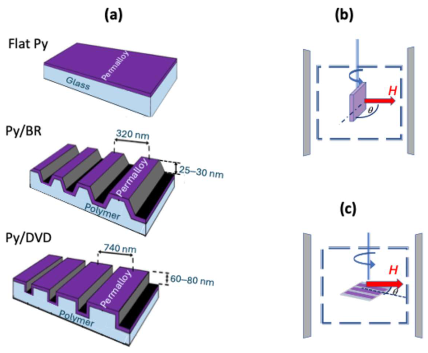
Permalloy is a nickel–iron magnetic alloy, typically composed of about 80% nickel and 20% iron, known for its exceptionally high magnetic permeability and low coercivity. It exhibits a high saturation magnetization of approximately 800 kA/m, allowing it to achieve strong magnetic responses under low external fields. Due to its low coercive force—typically less than 1 A/m—Permalloy can be easily magnetized and demagnetized, making it ideal for use in magnetic sensors, cores, and shielding applications. Its soft magnetic behavior arises from its well-ordered crystalline structure and minimal magneto-crystalline anisotropy [37]. Thin films of permalloy with the thickness of 40 nm are deposited via dc sputtering onto three substrates: a flat glass slide and polymer profile-modulated substrates with different profile modulation. The profile-modulated polycarbonate substrates are derived from commercial digital memory DVD and Blu-ray discs following [38]. Film thicknesses are verified using a stylus profilometer and a flat film, which is deposited at the same deposition run. The profiles of the structures are shown in Figure 1a. The film deposited on the Blu-ray substrate, Py/BR, has a period of 320 nm and modulation height of 20–30 nm, while the film on the DVD substrate, Py/DVD, has a nearly rectangular profile modulation with the period of 740 nm and a height of 60–80 nm as confirmed by Atomic Force Microscope (AFM) characterization.
In the experiment, we used the Bruker EMX-Plus Electron Magnetic Resonance Spectrometer with the rectangular resonator cavity ER 4102ST operating in the TE102 mode at the microwave frequency of 9.8 GHz (X Band). The orientations of the samples (vertical or horizontal) inside the microwave resonator are illustrated in Figure 1b,c. Since standard EPR spectrometers use field modulation and phase-sensitive detection for enhanced sensitivity, recorded signals correspond to the first derivative of the microwave absorption over field, which is modulated with the frequency of 100 kHz and amplitude of 0.1–1 Oe.

3. Results

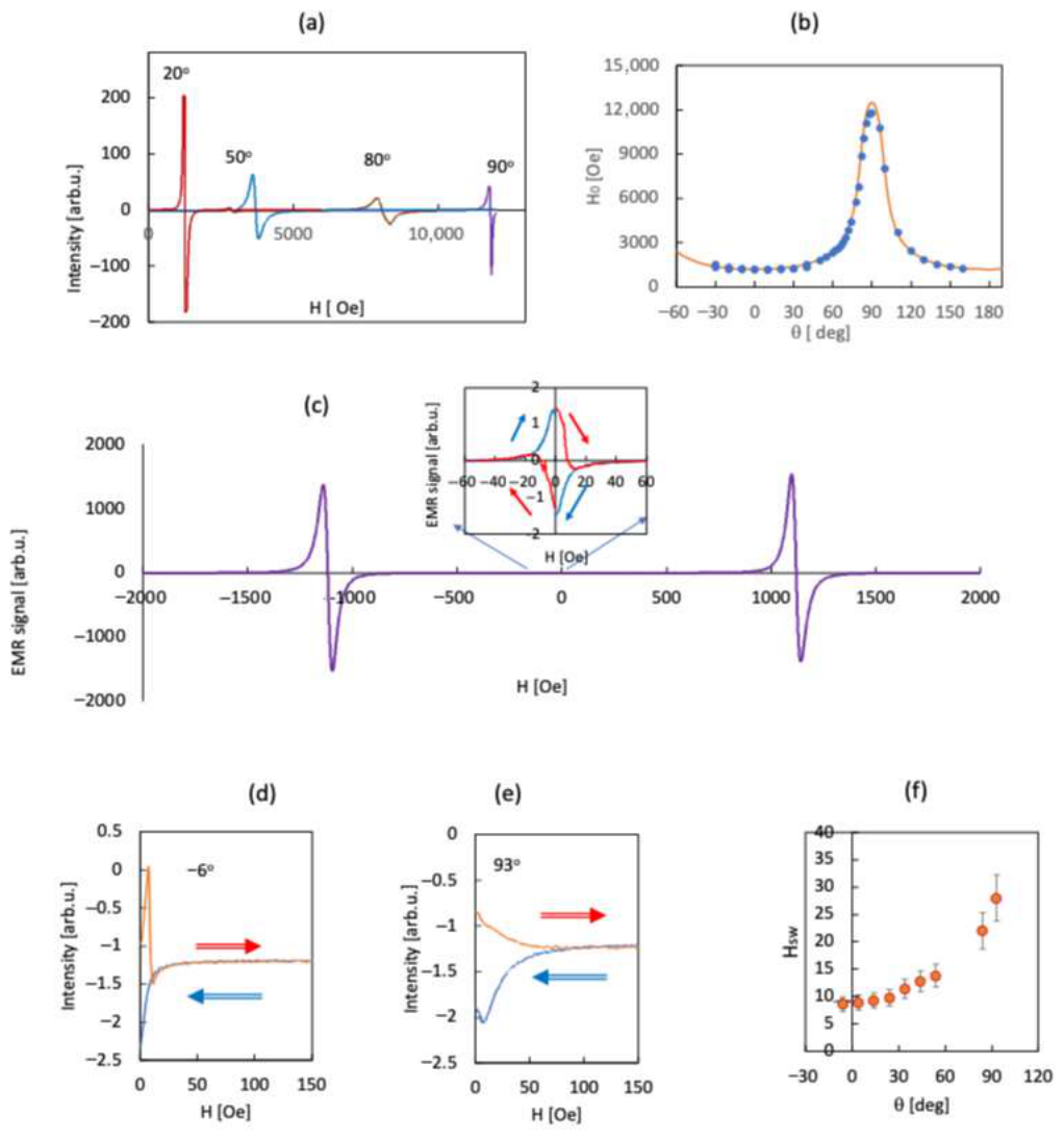
The results obtained in flat films are presented in Figure 2. The film is placed vertically in the resonator and oriented at different angles θ in respect to external magnetic field as shown in Figure 1b. Typical FMR signals (derivatives of the microwave absorption) are shown in Figure 2a. The position of the absorption maximum, H0 (determined as the middle point between maximum and minimum of the signal) strongly depends on the orientation angle Figure 2b. Theoretically, in flat films, the ferromagnetic resonance condition reads [35]
(ω0/γ)2 = (H0cos (ϕα) − Meffcos2ϕ) (H0 cos (ϕα) − Meffcos2ϕ),
where w0 is the microwave frequency, γ is the gyromagnetic ratio, H0 is the magnetic field, Meff is the effective magnetization, which is determined by the saturation magnetization Ms and may have contributions from crystalline anisotropy, α = π/2 − θ is the angle between the external magnetic field and direction z, which is normal to the film plane. ϕ is the angle between direction of the magnetization and z, and can be found by the equilibrium condition:
H sin (ϕα) − 1/2 Meff sin (2ϕ) = 0.
The experimental points can be fitted with calculations assuming Meff = 7.2 × 10⁵ A/m which is in the range of typical saturation magnetization of permalloy [24,37].
Besides the FMR signals, some additional features can be observed at low-fields, see Figure 2c–e. These signals demonstrate an interesting “memory” behavior, depending on the previous magnetic exposure of the sample. If the film is not exposed previously to the magnetic field, the low-field EMR signal recorded at the increasing external magnetic field (during the sweep upward) strongly differs from that recorded during the sweep downward. This difference is observed only during the first sweep. If the sweep is repeated, the signal is the same as that recorded at the sweep downward during the first sweep. Thus, the evolution of the signal at the sweeping field depends on the initial state of magnetization as it commonly takes place during the recording hysteresis loop in ferromagnetic materials.
Since a standard EMR spectrometer does not provide the option of changing the magnetic field in the opposite direction, we use the following procedure in recording low-field signals: After first experimental runs “up” and “down”, we rotate the sample in a zero field by 180 degree and sweep the field upward and downward again considering now the direction of the field to be negative and multiplying the signals by −1. The procedure with the rotation of the sample by 180 deg in a zero field can be repeated, producing a hysteresis loop at low fields, see inset in Figure 2c. There is no hysteresis in the main FMR signals observed in larger fields, where upward and downward runs produce the same curves. The difference between upward and downward runs is observed only at low fields (less than hundred Oe in flat films).
Low-field microwave absorption is reported in manganite films [39] and ascribed to the reorientation of magnetic domains. Effects observed in our work can be of similar origin. This hypothesis can explain the presence of the hysteresis. During the first sweep upward, magnetic domains become oriented. If the sweep is repeated in the same direction, it does not affect the domain orientation, and signals on the consecutive runs coincide with each other. However, if after the first run, the sample is rotated by 180° at a zero field, domains become magnetized in the opposite direction. The upward run would reorient the domains, and the signal observed at the increasing field would be different from that observed during decreasing field.
Note that the shape of our signal is highly unusual for typical EMR signals and could not be fully associated with the derivative of the microwave absorption commonly recorded by EPR spectrometers. The signal (see inset in Figure 2c) is mostly positive at the upward sweep formally corresponding to an increase in the sample absorbance (associated with the imaginary part of magnetic susceptibility, χ″) and fully negative at the downward sweep, which would again correspond to an increase in χ″. Continuing sweeping over the loop, each run up and down would formally result in an increase in χ″. This does not have any physical meaning and is not expected in common EMR experiments. Changing parameters of EMR detection (varying sweep rates between 1 Oe/s and 0.03 Oe/s and modulation amplitude between 1 Oe and 0.1 Oe) does not significantly affect the signal shape. Higher rates and amplitudes distort the signal. This unusual shape might be due to a contribution from the dispersion caused by a sharp and fast magnetization change like switching magnetic domains. According to [40], the domain switching rates in permalloy are in the nanosecond range. This is much faster than the characteristic response times of the spectrometer, and comparable with the period of the microwave field.
Let us estimate the effective switching field, HSW, as the midpoint between maximum and minimum during the sweep up. For common EMR signals, this point approximately corresponds to the absorption peak position. This interpretation cannot be fully applied to our case. Besides, the positions of maxima and minima are not always obvious. However, let us use these estimations for a qualitative comparison of the samples under study, keeping in mind that these are very rough estimations. In flat films, the hysteresis loops are relatively narrow, with HSW = 9 Oe observed for in-plane magnetic field. With an increase in θ, HSW gradually increases reaching ~30 Oe observed when H is perpendicular to the plane.
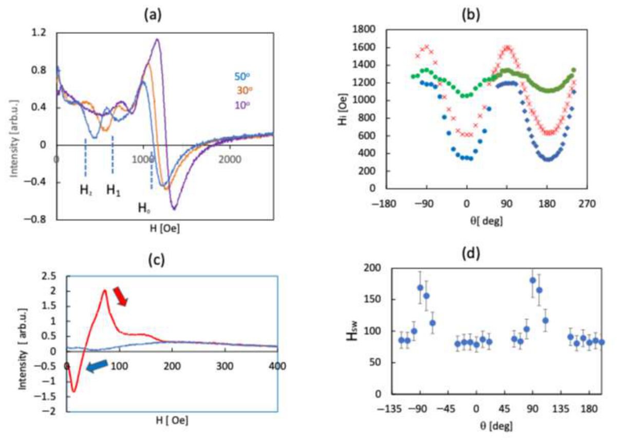
The EMR results obtained in gratings are shown in Figure 3 and Figure 4 for Py/DVD and Py/BR structures respectively. The gratings are mounted horizontally in the resonator (Figure 1c), corresponding to the magnetic field in-plane. In this geometry, the angle θ is the angle between the magnetic field and the direction of grooves. Typical EMR signals are shown in Figure 3a. In addition to the fundamental FMR, multiple spin-wave modes are observed, with their angular dependence mapped in Figure 3b.
The FMR and spin waves in the structures with the same geometry (permalloy flat films and DVD-based gratings with the rectangular profile modulation, modulation height of 80 nm, modulation period of 740 nm and permalloy film thickness of 50 nm) have been studied experimentally and theoretically in [27]. It was shown that similarly to the crystalline films with growth-induced in-plane uniaxial anisotropy [26], the angular dependence of the main resonance in the gratings corresponds to in-plane uniaxial magnetic anisotropy and can be fitted with
(ω0/γ 2= (H0 + M + HA cos2 θ) (H0 + HA cos 2θ)
with the anisotropy field of HA = 120 Oe (9.56 kA/m).
Micromagnetic simulations were performed in [27] based on the Landau–Lifshitz–Gilbert equation. Considering the same geometry as in the EMR experiment, absorption at the 10 GHz frequency was calculated following the approach in [11] as the function of the external magnetic field. The numerical simulations predicted a single FMR peak in flat films and several additional resonance peaks in profile-modulated structures with the positions dependent on the orientation. The peaks were ascribed to the resonance modes formed by the magnetic surface spin (MSSW) waves with k-vectors corresponding to the condition, k = N π/d cos θ, where d is the grating period and N is an integer. The angular dependence of the peak positions (H0, H1, H2 in Figure 3) observed in the current work closely correspond to those previously observed and calculated in ref. [27].
Let us now concentrate on the low-field signals which are not predicted by the simulations [27] and display a clear hysteresis between upward and downward field sweeps (Figure 3c). The signal recorded at the sweep “up” is much higher than that recorded at the sweep “down” with a sharp peak. Rough estimations of HSW in Py/DVD as the function of the sample orientation are shown in Figure 3d. The typical fields are 75–80 Oe for low θ and sharply grow when the field becomes perpendicular to grooves.
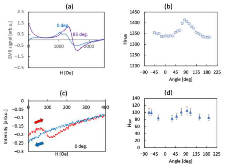
In Py/BR structures the signals are broader than in Py/DVD structures. Spin-wave resonances are present there as well; however, clear assignment of their positions is not possible because of their broadness. The angular dependence of the main resonance is shown in Figure 4b. Fitting with the Equation (3) gives HA = 45 Oe (=3.6 kA/m). The low-field signals show the same hysteresis behavior. The estimated switching fields are shown in Figure 4d.
Thus, our experiments in permalloy films and gratings reveal the presence of low-field EMR signals, which have an unusual shape and depend on the previous exposure of the sample to the magnetic field. The origin of these effects can be attributed to the fast switching of magnetic domains which may contribute to both the absorption and dispersion of the EMR signal.
This low-field behavior strongly depends on the geometry of the structure and its orientation vs magnetic field. The switching fields are the lowest in flat films with HSW = 9 Oe for the field in plane. In gratings, the lowest switching fields are in the range of 80 Oe and observed when the field is parallel to the direction of grooves. The orientation dependence of HSW grows resembles the orientation dependence of the FMR signals, compare Figure 2b,f (flat film), Figure 3b,d (Py/DVD) and Figure 4b,d; however, the character of this dependence can be different, indicating the role of domain shapes in each case.
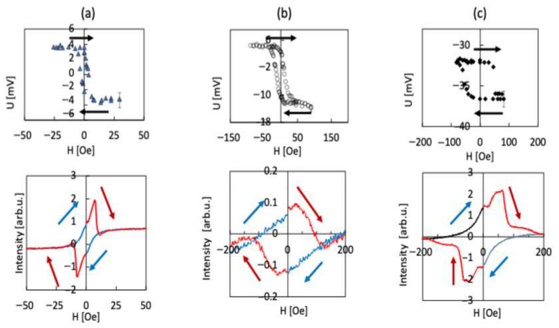
Let us now compare the low-field EMR results with the switching effects observed in photovoltage experiments. In Figure 5, we plot the photovoltage hysteresis curves observed in the flat films and gratings (these results are reported in [30]) and typical low-field signals observed in our structures which have the same geometry (and were obtained in the same fabrication batch as samples in [30]). The curves are measured at the H in-plane (which corresponds to the magnetic field orientation in the photovoltage setup). As one can see, the hysteresis loops observed in the photovoltage and EMR signals are the narrowest in flat films, having the width of a few Oe. They become broader in the gratings reaching several tens Oe. In Py/DVD, the photovoltage and EMR loop widths approximately correspond to each other; however, in Py/BR, the loop of the photovoltage looks narrower than that in the EMR signals, indicating that the direct comparison of such hysteresis loops may not be fully correct.
In Table 1, we list typical photovoltage switching fields observed in various experiments [29,30,31,32] with permalloy films and gratings and gold permalloy bilayers of the same geometry. We compare them with characteristic fields estimated from the EMR experiments: (i) HSW estimated as discussed above, (ii) the peak position, Hp, recorded during the upward sweep, and (iii) the irreversibility field, Hi, above which the sweep upward starts to coincide with the sweep downward. As one can see, the peak position, Hp, is the best candidate to fit the results observed in the photovoltage and can be considered as a signature of the most efficient domain switching. Hi fields are the fields at which all domains are reoriented in the field direction.
In conclusion, the low-field EMR in permalloy films and gratings demonstrates signals which depend on the previous magnetic exposure of the sample and form a hysteresis loop in sweeping fields. The signals are attributed to the sharp switching of magnetic domains and are likely to have both absorption and dispersion contributions. We believe that such low-field signals may exist in various magnetic materials or materials with magnetic inclusions but are overlooked in common EMR experiments, since the observation requires specific steps including slow sweeps up and down and the rotation of the sample by 180° in zero fields between sweeps.
The shapes and widths of the loops are very different for permalloy films and gratings, which is similar to the results of the photovoltage experiments, thus confirming the possibility to design magnetic properties and photovoltage switching effects with nanoscale geometry.

Author Contributions

Conceptualization—N.N.; Data curation, Formal analysis—N.N., S.N., M.H., M.A.R., T.B.; Writing—N.N., S.N.; Funding acquisition—N.N.; Review/Editing—N.N., S.N., M.H., M.A.R., T.B. All authors have read and agreed to the published version of the manuscript.

Funding

This work was funded by NSF (2112595), (2301350), and DOE (DE-NA0004007).

Data Availability Statement

The original contributions presented in this study are included in the article. Further inquiries can be directed at the corresponding author.

Acknowledgments

Crystal R. Petersen, for drawings provided in Figure 1a. All contributors have read and agreed to the published version of the manuscript.

Conflicts of Interest

The authors declare no conflicts of interest. The funders had no role in the design of the study; in the collection, analyses, or interpretation of data; in the writing of the manuscript; or in the decision to publish the results.

References

  1. Adenot-Engelvin, A.L.; Dudek, C.; Toneguzzo, P.; Acher, O. Microwave properties of ferromagnetic composites and metamaterials. J. Eur. Cer. Soc. 2007, 27, 1029–1033. [Google Scholar] [CrossRef] [Scilit]
  2. Heyderman, L.J.; Stamps, R.L. Artificial ferroic systems: Novel functionality from structure, interactions and dynamics. J. Phys. Condens. Matter 2013, 25, 363201. [Google Scholar] [CrossRef] [Scilit]
  3. Morales, C.; Dewdney, J.; Pal, S.; Skidmore, S.; Stojak, K.; Srikanth, H.; Weller, T.; Wang, J. Tunable magneto-dielectric polymer nanocomposites for microwave applications. IEEE Trans. Microw. Theory Tech. 2011, 59, 302–309. [Google Scholar] [CrossRef] [Scilit]
  4. Noginova, N.; Williams, Q.L.; Dallas, P.; Giannelis, E.P. Magnetic nanoparticles for tunable microwave metamaterials. In Proceedings of the SPIE 8455, Metamaterials: Fundamentals and Applications V, San Diego, CA, USA, 12–16 August 2012; p. 845531. [Google Scholar]
  5. Mruczkiewicz, M.; Krawczyk, M.; Mikhaylovskiy, R.V.; Kruglyak, V.V. Towards high-frequency negative permeability using magnonic crystals in meta material design. Phys. Rev. B 2012, 86, 024425. [Google Scholar] [CrossRef] [Scilit]
  6. Fischbacher, J.; Kovacs, A.; Oezelt, H.; Gusenbauer, M.; Suess, D.; Schrefl, T. Effective uniaxial anisotropy in easy-plane materials through nanostructuring. Appl. Phys. Lett. 2017, 111, 192407. [Google Scholar] [CrossRef] [Scilit]
  7. Nikitov, S.; Tailhades, P.; Tsai, C. Spin waves in periodic magnetic structures—Magnonic crystals. J. Magn. Magn. Mater. 2001, 236, 320–330. [Google Scholar] [CrossRef] [Scilit]
  8. Kruglyak, V.V.; Demokritov, S.O.; Grundler, D. PREFACE: Magnonics Magnonics. J. Phys. D. Appl. Phys. 2010, 43, 264001. [Google Scholar] [CrossRef] [Scilit]
  9. Vysotskii, S.L.; Nikitov, S.A.; Filimonov, Y.A. Magnetostatic spin waves in two-dimensional periodic structures (magnetophoton crystals). J. Exp. Theory Phys. 2005, 101, 547–553. [Google Scholar] [CrossRef] [Scilit]
  10. Sokolovskyy, M.L.; Krawczyk, M. The magnetostatic modes in planar one-dimensional magnonic crystals with nanoscale sizes. J. Nanopart. Res. 2011, 13, 6085–6091. [Google Scholar] [CrossRef] [Scilit]
  11. Beginin, E.N.; Sadovnikov, A.V.; Sakharov, V.K.; Stognij, A.I.; Khivintsev, Y.V.; Nikitov, S.A. Collective and localized modes in 3D magnonic crystals. J. Magn. Magn. Mat. 2019, 492, 165647. [Google Scholar] [CrossRef] [Scilit]
  12. Vasseur, J.O.; Dobrzynski, L.; Djafari-Rouhani, B.; Puszkarski, H. Magnon band structure of periodic composites. Phys. Rev. B 1996, 54, 1043. [Google Scholar] [CrossRef] [Scilit]
  13. Rychły-Gruszecka, J.; Walowski, J.; Denker, C.; Tuband, T.; Mutzenberg, M.; Klos, J.W. Shaping the spin wave spectra of planar 1D magnonic crystals by the geometrical constraints. Sci. Rep. 2022, 12, 20678. [Google Scholar] [CrossRef] [Scilit] [PubMed]
  14. Wang, Z.K.; Zhang, V.L.; Lim, H.S.; Ng, S.C.; Kuok, M.H.; Jain, S.; Adeyeye, A.O. Observation of frequency band gaps in a one-dimensional nanostructured magnonic crystal. Appl. Phys. Lett. 2009, 94, 083112. [Google Scholar] [CrossRef] [Scilit]
  15. Horaguchi, T.; Takeda, Y.; Manago, T. Modulation of magnonic band structure via wall width variations in 1D magnonic crystals. J. Phys. D Appl. Phys. 2025, 58, 365005. [Google Scholar] [CrossRef] [Scilit]
  16. Gubbiotti, G.; Sadovnikov, A.; Beginin, E.; Sheshukova, S.; Nikitov, S.; Talmelli, G.; Asselberghs, I.; Radu, I.P.; Adelmann, C.; Ciubotaru, F. Magnonic band structure in CoFeB/Ta/NiFe meander-shaped magnetic bilayers. Appl. Phys. Lett. 2021, 118, 162405. [Google Scholar] [CrossRef] [Scilit]
  17. Sadovnikov, A.; Talmelli, G.; Gubbiotti, G.; Beginin, E.; Sheshukova, S.; Nikitov, S.; Adelmann, C.; Ciubotaru, F. Reconfigurable 3D magnonic crystal: Tunable and localized spin-wave excitations in CoFeB meander-shaped film. J. Magn. Magn. Mater. 2022, 544, 168670. [Google Scholar] [CrossRef] [Scilit]
  18. Saavedra, E.; Escrig, J. Dynamic susceptibility of interconnected pentagonal spin ice lattices. J. Magn. Magn. Mater. 2020, 513, 167084. [Google Scholar] [CrossRef] [Scilit]
  19. Armelles, G.; Cebollada, A.; García-Martín, A.; González, M.U. Magnetoplasmonics: Combining magnetic and plasmonic functionalities. Adv. Opt. Mater. 2013, 1, 10–35. [Google Scholar] [CrossRef] [Scilit]
  20. Temnov, V.V.; Woggon, U.; Dintinger, J.; Devaux, E.; Ebbesen, T.W. Active magneto-plasmonics in hybrid metal–ferromagnet structures. Nat. Photonics 2010, 4, 107–111. [Google Scholar] [CrossRef] [Scilit]
  21. Maccaferri, N.; Gabbani, A.; Pineider, F.; Kaihara, T.; Tapani, T.; Vavassori, P. Magnetoplasmonics in confined geometries: Current challenges and future opportunities. Appl. Phys. Lett. 2023, 122, 120502. [Google Scholar] [CrossRef] [Scilit]
  22. Zubritskaya, I.; Maccaferri, N.; Ezeiza, X.I.; Vavassori, P.; Dmitriev, A. Magnetic Control of the Chiroptical Plasmonic Surfaces. Nano Lett. 2018, 18, 302. [Google Scholar] [CrossRef] [Scilit] [PubMed]
  23. Armelles, G.; Bergamini, L.; Zabala, N.; González, M.U.; García, F.; Alvaro, R.; Aizpurua, J.; Cebollada, A. Broad band infrared modulation using spintronic-plasmonic metasurfaces. Nanophotonics 2019, 8, 1847. [Google Scholar] [CrossRef] [Scilit]
  24. Berendt, J.; Teixeira, J.M.; García-García, A.; Raposo, M.; Ribeiro, P.A.; Dubowik, J.; Kakazei, G.N.; Schmool, D.S. Tunable magnetic anisotropy in permalloy thin films grown on holographic relief gratings. Appl. Phys. Lett. 2014, 104, 082408. [Google Scholar] [CrossRef] [Scilit]
  25. Mollick, S.A.; Singh, R.; Kumar, M.; Bhattacharyya, S.N.; Som, T. Strong uniaxial magnetic anisotropy in Co films on highly ordered grating-like nanopatterned Ge surfaces. Nanotechnology 2018, 29, 125302. [Google Scholar] [CrossRef] [Scilit]
  26. Zhang, Y.-J.; Wu, L.; Ma, J.; Zhang, Q.-H.; Fujimori, A.; Ma, J.; Lin, Y.-H.; Nan, C.-W.; Sun, N.-X. Interfacial orbital preferential occupation induced controllable uniaxial magnetic anisotropy observed in Ni/NiO(110) heterostructures. npj Quant. Mater. 2017, 2, 17. [Google Scholar] [CrossRef] [Scilit]
  27. Noginova, N.; Gubanov, V.; Shahabuddin, M.; Gubanova, Y.; Nesbit, S.; Demidov, V.V.; Atsarkin, V.A.; Beginin, E.N.; Sadovnikov, A.V. Ferromagnetic Resonance in Permalloy Metasurfaces. Appl. Magn. Reson. 2021, 52, 749–758. [Google Scholar] [CrossRef] [Scilit]
  28. Shahabuddin, M.; Noginova, N. Plasmonic System with In-Plane Magnetic Anisotropy for Plasmon Based Magnetic Switching. In Proceedings of the 2019 Conference on Lasers and Electro-Optics (CLEO), San Jose, CA, USA, 5–10 May 2019. [Google Scholar]
  29. Shahabuddin, M.; Keene, D.W.; Durach, M.; Posvyanskii, V.S.; Atsarkin, V.A.; Noginova, N. Magnetically dependent plasmon drag in permalloy structures. J. Opt. Soc. Am. B 2021, 38, 2012–2018. [Google Scholar] [CrossRef] [Scilit]
  30. Rab, A.; Keene, D.W.; Nesbit, S.; Baker, T.; Noginova, N. Magnetically dependent photovoltages in permalloy films and gratings. Sci. Rep. 2025, 15, 2543. [Google Scholar] [CrossRef] [Scilit]
  31. Rab, M.A.; Keene, D.W.; Noginova, N. Probing magnetization with photovoltage. In Frontiers in Optics + Laser Science 2023; (FiO, LS) Technical Series; Optica Publishing Group: Tacoma, WA, USA, 2023; paper JTu5A.4. [Google Scholar]
  32. Noginova, N.; Rab, M.A.; Nesbit, S.; Baker, T. Coupling of optical, magnetic, and electric effects in permalloy and gold-permalloy bilayer structures. In Proceedings of the SPIE 13109, Metamaterials, Metadevices, and Metasystems, San Diego, CA, USA, 18–23 August 2024; p. 1310905. [Google Scholar]
  33. Yin, S.L.; Mao, Q.; Meng, Q.Y.; Li, D.; Zhao, H.W. Hybrid anomalous and planar Nernst effect in permalloy thin films. Phys. Rev. B 2013, 88, 064410. [Google Scholar] [CrossRef] [Scilit]
  34. Miao, B.F.; Huang, S.Y.; Qu, D.; Chien, C.L. Inverse Spin Hall Effect in a Ferromagnetic Metal. Phys. Rev. Lett. 2013, 111, 066602. [Google Scholar] [CrossRef] [Scilit]
  35. Kittel, C. On the theory of ferromagnetic resonance absorption. Phys. Rev. 1948, 73, 155–161. [Google Scholar] [CrossRef] [Scilit]
  36. Krishtopenko, S.S.; Gavrilenko, V.I.; Goiran, M. Spin-wave excitations and electron spin resonance in symmetric and asymmetric narrow-gap quantum wells. Phys. Rev. B 2013, 87, 155113. [Google Scholar] [CrossRef] [Scilit]
  37. Chikazumi, S. Physics of Ferromagnetism; Oxford University Press: Oxford, UK, 1997. [Google Scholar]
  38. Keene, D.; Ronurpraful, T.; Nogniova, N. Plasmon related electrical effects in strongly modulated metasurfaces. In Proceedings of the SPIE 11080, Metamaterials, Metadevices, and Metasystems 2019, San Diego, CA, USA, 11–15 August 2019; p. 110801C. [Google Scholar]
  39. Golosovsky, M.; Monod, P.; Muduli, P.K.; Budhani, R.C. Low-field microwave absorption in epitaxial La0.7Sr0.3MnO3. Phys. Rev. B 2012, 85, 184418. [Google Scholar] [CrossRef] [Scilit]
  40. Chumakov, D.; McCord, J.; Schäfer, R.; Schultz, L.; Vinzelberg, H.; Kaltofen, R.; Mönch, I. Nanosecond time-scale switching of permalloy thin film elements studied by wide-field time-resolved Kerr microscopy. Phys. Rev. B 2005, 71, 014410. [Google Scholar] [CrossRef] [Scilit]
Figure 1. (a) Schematics of the structures; (b) vertical and (c) horizontal orientation of samples in the microwave resonator. The arrows show the direction of the external field H.
Magnetochemistry 12 00061 g001
Figure 2. EMR in flat films at vertical orientation. (a) FMR at various angles as indicated; (b) angular dependence of the FMR position, experiment (points) and fitting (solid trace); (c) typical experimental recording with low-field hysteresis (magnified at inset); (d,e) low-field signals at various angles as indicated. Arrows show the direction of the field sweep (red—up, blue—down). (f) Angular dependence of switching fields.
Magnetochemistry 12 00061 g002
Figure 3. EMR in Py/DVD: (a) main FMR and spin resonances at various orientations, (b) angular dependence of the line positions (Green H0, Red H1, Blue H2); (c) typical low-field signals at the sweeping field up (red) and down (blue), θ = 30°; (d) angular dependence of the HSW.
Magnetochemistry 12 00061 g003
Figure 4. EMR in Py/BR: (a) FMR and spin resonances at various orientations, (b) angular dependence of FMR position; (c) typical low-field signals at the sweeping field up (red) and down (blue), θ = 0°; (d) angular dependence of the HSW.
Magnetochemistry 12 00061 g004
Figure 5. Photovoltages [30] (top) and low-field signals (bottom) in (a) flat films, (b) Py/BR and (c) Py/DVD structures. Arrows show directions of magnetic field sweep.
Magnetochemistry 12 00061 g005
Table 1. Characteristic fields for photovoltage and low-field EMR in permalloy films and gratings.
StructuresPhotovoltageLow-Field EMR
Hpsw (Oe) HSW (Oe)Hp (Oe)Hi (Oe)
Flat Py3–5 [30,32]9 ± 1.45.8 ± 0.612 ± 4
Flat Au/Py2–5 [32]
Py/Br19–25 [30]80 ± 833 ± 0.3220 ± 50
Au/Py/Br40–50 [32]
Py/DVD70–90 [29,30]82 ± 863 ± 0.6190 ± 40
Au/Py/DVD70–90 [32]
Disclaimer/Publisher’s Note: The statements, opinions and data contained in all publications are solely those of the individual author(s) and contributor(s) and not of MDPI and/or the editor(s). MDPI and/or the editor(s) disclaim responsibility for any injury to people or property resulting from any ideas, methods, instructions or products referred to in the content.