Article

Microstructural, Mechanical, Thermal, and Magnetic Properties of the Mechanically Alloyed and Consolidated Al–16 wt. % Mn–7 wt. % Cu Alloy

1
Laboratory of Magnetism and Spectroscopy of Solids (LM2S), Physics Department, Badji Mokhtar Annaba University, Annaba 23000, Algeria
2
Department de Fisica, Universitat de Girona, Campus Montilivi, 17071 Girona, Spain
3
Physics Department, Faculty of Sciences, Badji Mokhtar Annaba University, Annaba 23000, Algeria
*
Author to whom correspondence should be addressed.
Magnetochemistry 2025, 11(7), 59; https://doi.org/10.3390/magnetochemistry11070059
Submission received: 29 May 2025 / Revised: 4 July 2025 / Accepted: 7 July 2025 / Published: 11 July 2025

Abstract

The effect of severe plastic deformation during milling and conventional and Spark Plasma Sintering (SPS) on the wt. % microstructural, structural, thermal, magnetic, and mechanical properties of the Al–16 wt. % Mn–7 wt. % Cu alloy was studied. A milling process for up to 24 h (A24) leads to microstructure refinement and the presence of Al, Mn, and Cu solid solutions. The energy dispersive spectroscopy (EDS) analysis reveals the existence of Cu–Al, Mn–Al, and Al–Mn enriched particles. The powders exhibit weak ferromagnetism and an exchange bias (EB) behaviour that decreases with increasing milling time. The Ms values fitted using the law of approach to saturation (LAS) are comparable to the experimental values. The exothermic and endothermic peaks that appear in the differential scanning calorimetry (DSC) scans in the 500–900 °C range on heating/cooling are related to different phase transformations. The crystal structure of the A24 powders heated up to 900 °C (A24_900 °C) consists of a dual-phase microstructure of Al20Cu2Mn3 nanoprecipitates (~28%) and Al matrix (~72%). The sintering of the A24 powders at 500 °C for one hour (A24S) leads to the precipitation of Al6Mn, Al2Cu, and the Al20Cu2Mn3 T-phase into the Al-enriched matrix. In contrast, the consolidation by SPS (A24SPS) leads to a mixture of an Al solid solution, Al6Mn, T-phase, and α-Mn with an increased weight fraction of the T-phase and Al6Mn. The sintered samples exhibit the coexistence of a significant PM/AFM contribution to the M-H curves, with increasing Hc and decreasing EB. A higher microhardness value of about 581 HV is achieved for the A24SPS sample compared to those of the A24 (68 HV) and A24S (80 HV) samples.

1. Introduction

The powder metallurgy (P/M) method for manufacturing metal matrix composites (MMCs) offers advantages over ingot metallurgy or diffusion welding. Indeed, its low manufacturing temperature minimises undesired reactions between the matrix and reinforcement. Additionally, the uniform distribution of reinforcement enhances the structural properties and reproducibility [1]. MMCs possess advantages over other composites due to their capability to withstand high temperatures, moisture, and radiation, and exhibit zero outgassing under vacuum conditions. Additionally, they offer enhanced thermal and electrical conductivities, as well as improved mechanical properties [2]. Among the P/M methods, mechanical alloying (MA), a top-down approach, is widely used to produce homogeneous materials by reducing the size of elemental or pre-alloyed powders to the nanometre scale. As the vials rotate, the ball-powder-ball and ball-powder-vial interactions lead to repetitive collisions between the powder particles under high-energy impact. This dynamic process induces strain hardening and particle fracture, reduces the particle size, and promotes the formation of new phases through cold welding and agglomeration [3]. This severe plastic deformation results in nanocrystalline (NC) structures characterised by a high dislocation density and increased vacancy concentration [4]. As a result, the solute content and final properties of the alloys can be influenced by the alloy’s composition and milling parameters [5,6,7]. MA produces NC structures, enabling the high solubility of various alloying elements (e.g., Mn, Fe, Zr, etc.) in Al, even for elements with low solubility or immiscibility [8,9,10,11]. The enhanced solubility at room temperature (RT) exceeds rapid solubilisation, particularly when RT solubility is low.
Due to their low density and excellent physical properties, aluminium (Al) alloys and metal matrix composites are widely used in various industrial sectors, particularly in marine, aerospace, and automotive applications. The increased adoption of battery-powered electric vehicles (BEVs) has significantly increased the need for lightweight materials in the automotive industry, as reducing vehicle weight is crucial for balancing the higher mass of BEVs compared to gasoline- or diesel-powered vehicles [1,12,13]. Moreover, they are cheap compared to other low-density alloys such as Mg or Ti, in addition to their low processing costs and high versatility. The strength properties of Al are enhanced by alloying elements, such as manganese (Mn) and copper (Cu), through solid solution and precipitation-strengthening mechanisms [14]. Indeed, the addition of Mn to Al alloys enhances the strength due to the high thermal stability of Mn-bearing precipitates, the excellent corrosion resistance of Al-Mn alloys, and the low cost of Mn. The equilibrium solubility limit of Mn in Al is 0.62 at. % [7]. MA significantly increases the solubility limit of Mn in NC Al alloys, reaching 3.1 at. % after 200 h of milling. This process also reduces the crystallite size of the Al matrix to approximately 12 nm, with residual Mn forming uniformly dispersed micro- to nano-sized precipitates, leading to a primary strengthening effect [15]. Ruan and Schuh, using an electrodeposition method, prepared NC Al-Mn alloys with crystallite sizes below 100 nm, hardness values of about 5 GPa, and a tensile strength of over 1.5 GPa [16]. In Al-Mn-based alloys, the equilibrium orthorhombic Al6Mn phase forms during solidification and solution decomposition at elevated temperatures. Ageing between 300 and 400 °C leads to the precipitation of the icosahedral I-phase and Al12Mn compound [17]. Annealing at low temperatures for short durations promotes the formation of fine precipitates of metastable phases such as A l 12 M n ,   A l 19 M n 4 , A l 7 M n , and A l 4 M n intermetallics [18,19].
Copper is a strong element for solid solution strengthening in Al, contributing to strain hardening and grain refinement during milling. A high solute content correlates with the formation of ultrafine grains, approximately 25 nm in size, in both alloys. Thus, grain size emerges as a critical parameter that facilitates the increased solubility of alloying elements [20]. To produce bulk NC materials, mechanically alloyed powders undergo sintering at high temperatures [21], utilising various sintering processes, including hot extrusion [22], SPS, and hot-press sintering [23]. The SPS technique uses a pulsed direct current and uniaxial pressure, enabling high heating rates and facilitating rapid, low-temperature sintering. This process produces dense materials with enhanced properties without the need for pre-compaction or binders [24]. In Al composites reinforced with silicon carbide (SiC) nanoparticles, optimal properties were achieved for an Al-1 wt. % SiC sample using a 50 MPa pressure, a 200 °C/min heating rate, and a 600 °C sintering temperature for 10 min. The sample was consolidated with a uniform SiC distribution, resulting in a microhardness of 108 MPa and a compressive strength of 312 MPa [25].
Al-Mn-Cu-based alloys exhibit superior heat resistance, maintaining their performance at temperatures up to 250 °C. This is attributed to the strengthening effects of the Cu solid solution and the precipitation of the θ’ (CuAl) and Al20Cu2Mn3 phases [26,27]. Yakovtseva et al. studied the effects of the milling time and the addition of Al2O3 particles on the Al–15.3%, Mn–6.2%, Cu alloy during high-energy ball milling. It has been reported that milling for 5–20 h reduced the grain size from 53 µm to 38 μm. The addition of 2–5 vol.% Al2O3 further reduced the grain size and increased the microhardness from 300 HV to 520 HV. After 5 h of milling, the non-equilibrium phases Al2Cu and Al20Cu2Mn3 dissolved, enhancing the Mn and Cu solute contents in the Al matrix, with a maximum Mn solubility of 4.4 wt. % [14]. The processing parameters affect the crystal structure and the material’s properties. This study examines the effects of MA and consolidation, using conventional and SPS sintering, on the phase formation, morphology, magnetic properties, and thermal behaviour of the Al–16 wt. % Mn–7 wt. % Cu composite. It also reports the effect of processing parameters on the mechanical properties through the precipitation of the thermally stable Al20Cu2Mn3 intermetallic (T-phase). The latter is well known for its high strength at ambient and elevated temperatures.

2. Materials and Methods

The Al–16 wt. % Mn–7 wt. % Cu alloy was prepared from elemental Al (high-purity 99.99% size 325 mesh), Mn (purity 99.3%), and Cu (purity 99%) powders. MA was carried out in a Fritsch P7 high-energy planetary ball mill at room temperature using hardened steel balls and vials for 0, 3, 6, and 24 hours, which are referred to hereafter as A0, A3, A6, and A24. The process was carried out under an argon atmosphere to prevent oxidation, using ethanol as a process control agent (PCA) to avoid excessive cold welding. The ball-to-powder weight ratio was 3:2 with a total powder charge of 20 g, and the rotation speed was 200 rpm. After 3 and 6 h of milling, the vials were opened inside an argon glovebox to extract approximately 1.5 g of powder for analysis. Milling was processed for 15 min and stopped for 15 min to prevent overheating.
The A24 powders were subjected to continuous heating in an argon atmosphere from RT up to 900 °C at a heating/cooling rate of 10 °C/min in a differential scanning calorimeter (DSC, Labsys1600 °C, Setaram, Caluire-et-Cuire, France). Thus, it is named hereafter as A24_900 °C.
The A0, A3, A6, and A24 powders were compacted into pellets with a diameter of 13 mm and a thickness of 2 mm using a Specac manual press at 13 tons for 1 h. The pellets are named A0_pellet, A3_pellet, A6_pellet, and A24_pellet, respectively. The A24_pellet was sintered at 500 °C for one hour in a Nabertherm L189 tubular furnace (GmbH Bahnhofstr, Berlin, Germany) and cooled down to RT inside the furnace. Alumina crucibles held the samples inside the furnaces. The annealing was carried out in a vacuum quartz tube to prevent oxidation. The sintered pellet is labelled hereafter as A24S.
The so-called A24SPS was consolidated by the SPS equipment (model HHPD-25, FCT GmbH, Frankenblick, Germany) from the A24 powders after being placed into a graphite die, with sheets of graphitic paper inserted between the powder, punch, and die to facilitate easy removal after processing. The sample was heated at a rate of 100 °C/min to 500 °C, with a dwell time of 5 min maintained. A uniaxial pressure of 50 MPa was applied to the powder bed at RT and maintained throughout the heating process. All the pellets were mechanically ground using SiC paper of varying fineness and polished with Al2O3 and ethanol for the microstructural study and microindentation measurements.
X-ray diffraction (XRD, Malvern PANalytical Ltd., Malvern, UK) was used to investigate the phase formation by a PANalytical Empyrean diffractometer configured in a (2—θ) Bragg Brentano geometry using Co-Kα radiation (λCo = 1.78901 Å), a scan range of 30–100°, and a step size of 0.013°/min. The morphological analysis, microanalysis, and elemental mapping were performed using a scanning electron microscope (SEM, FEI QUANTA 250, Thermo Fisher, Waltham, MA, USA), an energy-dispersive X-ray spectrometer (EDS) produced by EDAX, and an EDS analysis software suite (Esprit version 2.5.1). The hysteresis cycles were measured on spherical samples (~40–50 mg in mass) for the milled powders, and a parallelepiped shape for the sintered A24S and A24SPS samples using a vibrating sample magnetometer (VSM, LakeShore 7404, Westerville, OH, USA) under a 12 kOe magnetic field.
Microindentation measurements were performed using a Vickers indenter on a Zwick/Roell instrument (GmbH & Co. KG, Eschwege, Germany) with a 1 N load and a 15 s dwell time. At least ten measurements were taken for each sample.

3. Results and Discussion

3.1. Mechanically Alloyed Powders

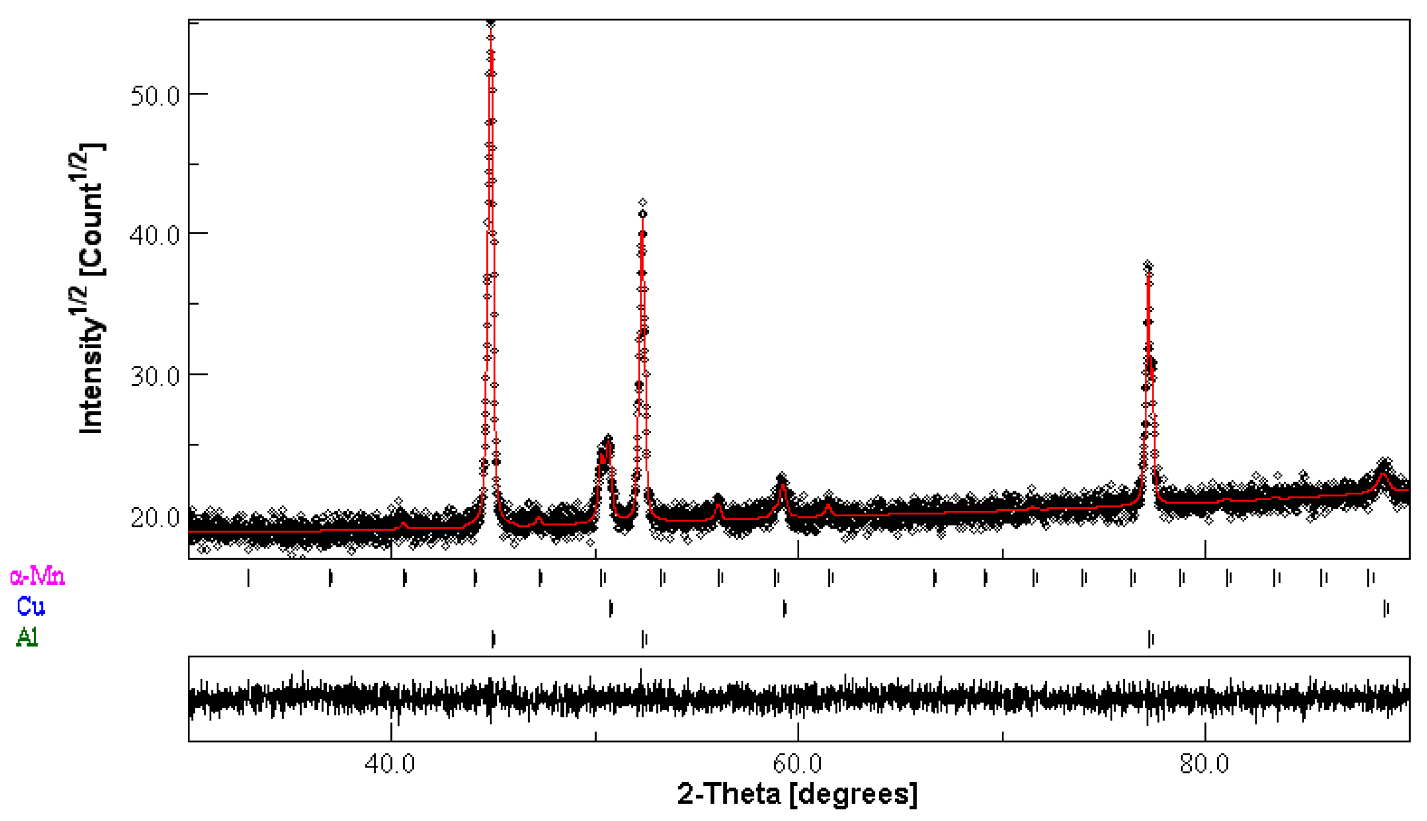
3.1.1. Structural Characterisation

MA enables the formation of alloys and phases in immiscible metallic systems by overcoming the limitations in phase diagrams. During milling, powder particles are subjected to repeated compressive forces between the balls and vials, resulting in deformations, fractures, and welding of the particles. These phenomena facilitate the formation of supersaturated solid solutions, amorphous alloys, NC structures, and intermetallic compounds through grain refinement, lattice disorder, and defect accumulation.
Figure 1 shows the XRD patterns of the A0, A3, A6, and A24 samples. The significant broadening of the Al (1 1 1), Cu (1 1 1), and Mn (0 3 3) diffraction peaks after 24 h of milling (see insets in Figure 1) is due to the diminution of the crystallite size to the nanoscale, the increase in the rate of micro deformations, and the accumulation of defects such as dislocations, grain boundaries, and vacancies.
The slight shift in the peak positions towards higher 2-theta angles can be attributed to reduced lattice parameters by the heavy plastic mechanical deformation, atomic size mismatch, intermetallic compounds, and solid solution formation through Cu and Mn diffusion with smaller atom radii into the Al matrix since rCu = 1.28 Å < rMn ≈ 1.37 Å < rAl ≈ 1.43 Å. Accordingly, substituting Al atoms by Cu and/or Mn atoms reduces interatomic distances and shrinks the lattice parameter. Solute atom diffusion during milling occurs along dislocation lines and is facilitated by the increased dislocation density induced by particle fracturing and cold welding. The relative difference in atomic radii among Al, Cu, and Mn can be quantified by the atomic size misfit parameter δ given by the following expression [28]:
δ = 100 i = 1 n c i ( 1 r i r ¯ ) 2 ,
with c A l = 0.77 , c C u = 0.07 , and c M n = 0.1 6, and the average atomic radius, r ¯ = c i r i , equals 1.409 Å. Additionally, the size misfit parameter, δ = 2.97%, suggests moderate strain and distortion in the crystal lattice. The mixing enthalpy of the ternary Al-Mn-Cu system can be estimated from binary mixing enthalpies using the following equation [28]:
Δ H m i x = i j c i c j Δ H m i x i j ,
with Al-Mn = −19 kJ/mol, Al-Cu = −1 kJ/mol, Mn-Cu = −7 kJ/mol [29], and Δ H m i x = 2.5 k J m o l .
The XRD patterns were analysed using MAUD software (version 2.9998) [30], enabling an accurate analysis of the resulting crystal structures. The Rietveld refinement (Figure 2) was performed using the face-centred cubic (FCC) Al and Cu (space group Fm3m, No. 225), lattice parameters a = b = c = 4.0497 Å (PCD file 1200487) and 3.6164 Å (PCD file 1412130), respectively, and cubic α-Mn (space group I-43m, No. 217, and a = b = c = 8.9182 Å, PCD file 558014).
The refined parameters of the A24 powder are summarised in Table 1. The crystallite sizes decrease with increasing milling time to approximately 175 nm, 62 nm, and 77 nm for Al, Cu, and α-Mn, respectively, after 24 h of milling. The repeated flattening, fracturing, and cold welding of the initial powder mixture create intimate contacts between the Al, Mn, and Cu elements, which are essential for subsequent solid-state reactions at relatively low temperatures. The formation of fresh interfaces between the Al, Mn, and Cu particles enhances atomic diffusion due to the significant density of defects generated during the milling process. The reduction in the lattice parameters results from the induced structural defects and foreign atoms during milling, confirming the intimate mixing of the Al, Cu, and Mn powders. The decrease in the lattice parameter of the Al matrix can be attributed to the diffusion of Mn/Cu atoms into its crystal lattice, resulting in the formation of a solid solution. The maximum solubility of Mn in Al is about 1.25 wt. % at 658 °C [31], and that of Cu is approximately 5.65 wt. % at 548 °C [32] and can be enhanced up to 7.5 wt. % due to microstructural refinement and the strain hardening effect during milling [33]. The low atom site occupancy value (0.602) of Al indicates the presence of vacancies and/or the substitution of Cu and Mn atoms for Al in its lattice. Furthermore, α-Mn shows a reduced lattice parameter by about −0.03% and atom site occupancy values lower than the unit (1) for the four Mn-type sites, in addition to slight variations in the atom site fractional coordinates (x, y, z) compared to the PCD file due to the structural defects induced through the heavy plastic deformation.

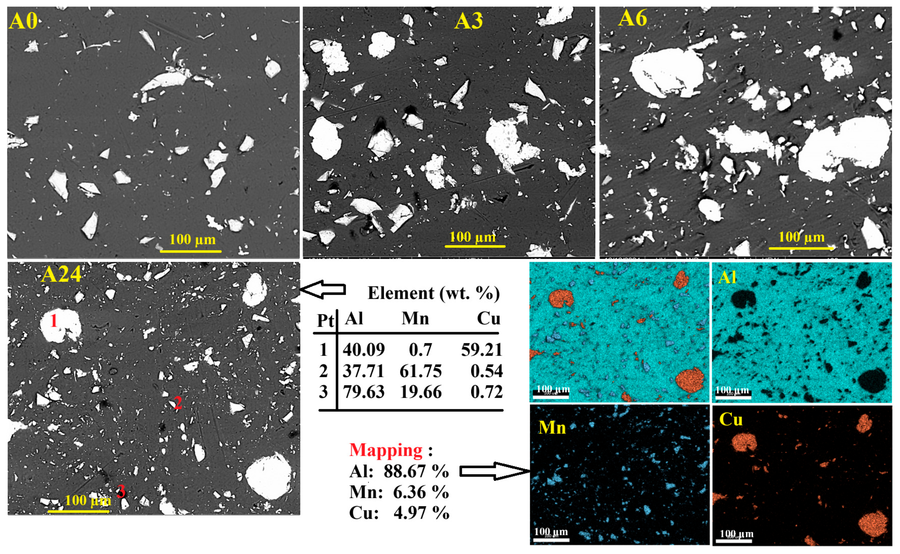
3.1.2. Morphology and EDS Analysis

Figure 3 shows the morphology of the A0, A3, A6, and A24 powder pellets. The initial A0 pellet exhibits irregular Cu and Mn particle shapes and a size distribution within the Al matrix. The effects of heavy plastic deformation and cold welding increase the particle size after 3 and 6 h of milling, due to the high ductility of Al and its lower melting temperature compared to Cu and Mn. Prolonged milling up to 24 h leads to a composite microstructure where smaller and a few bigger particles are dispersed into the Al matrix. The significant changes in the particles’ shape and size are related to the nature and alloying mechanisms of elemental Cu, Mn, and Al powders. Indeed, the presence of Mn as an alloying element contributes to faster grain and particle size refinement, accelerating its dissolution into the Al matrix. Additionally, the less ductile, hardened Cu promotes fracturing. Thus, fine Cu particles distribute more uniformly in the Al matrix.
EDS elemental mapping reveals that Mn is finely and homogeneously dispersed into the matrix, while Cu appears in coarser, localised zones. The elemental analysis (Table as inset in Figure 3) shows that the starting Al, Cu, and Mn elements are distributed among all the particles, forming larger Cu-enriched Al–Cu white inclusions (point 1), smaller Mn-enriched Al–Mn white particles (point 2), and a grey Al-enriched Al(Mn) solid solution (point 3) containing 79.66 wt. % Al and about 10.78 wt. % Mn. The SEM observation agrees well with the XRD results. The overall elemental EDS mapping composition is about 88.67 wt. % Al, 6.36 wt. % Mn, and 4.97 wt. % Cu.

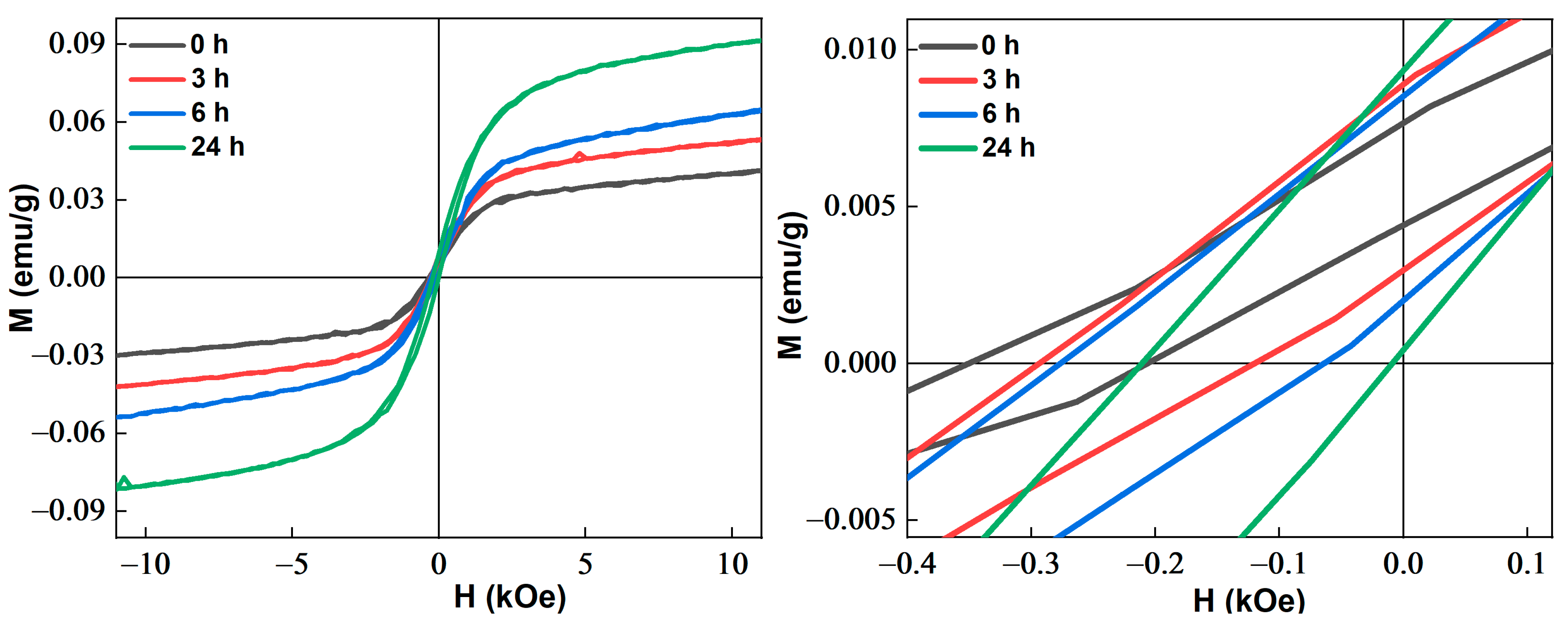
3.1.3. Magnetic Properties

Figure 4 shows the magnetization versus applied magnetic field M(H) curves (left side) of the A0, A3, A6, and A24 powders measured at RT and the enlargement of the central zone (right side). The hysteresis cycles show weak ferromagnetism and a non-saturated shape. Additionally, due to the exchange bias (EB) behaviour, the hysteresis curves exhibit a negative displacement along the applied magnetic field axis and a positive displacement along the magnetisation axis, as shown by the enlargement of the central region. The M-axis shift may be attributed to the short-range antiferromagnetic (AFM) coupling in the Mn-rich area. In contrast, the H-axis shift can be correlated with a heterogeneous AF/FM matrix, where the AF component’s interfacial pinning of FM spins gives rise to an EB behaviour. The EB likely stems from interfacial coupling between AFM regions and disordered magnetic phases.
Microstructural defects and processing methods such as MA, annealing, and hot compaction affect the magnetic behaviour of the Al-Mn-Cu alloys [34]. The solid solutions formed by substituting Mn, Cu, and Al atoms determine the magnetic phase and properties; thus, phase-separated ferromagnetic (FM) precipitates and structural transitions govern magnetism in Al-Mn-Cu alloys, which arises from Mn atoms (which carry magnetic moments) and their interactions. Mn provides the magnetic moments, while Cu and Al modify the lattice and electronic environment, tuning the magnetic interactions. Therefore, the magnetic properties of AlMnCu substitutional solid solutions result from the interplay between atomic substitution, crystal structure changes, and electron spin interactions within the alloy lattice. The degree of substitution and atomic ordering determine the magnetic properties. Additionally, the magnetocrystalline anisotropy can hinder the magnetisation of the crystal.
Figure 5a shows the variations in coercivity and exchange bias during milling. The coercivity and exchange bias are calculated using H c = H 1 H 2 2 and H E = ( H 1 + H 2 ) 2 , respectively; H 1 and H 2 represent the negative and the positive field values at zero magnetisation. The coercivity increases to approximately 106 Oe during the early milling stage (up to six) due to the pinning of domain walls resulting from the high density of structural defects and microstrains introduced by MA. It may also be related to the increases in the particle size and agglomeration of the powder particles, as cold welding dominates in the early milling stage. Further milling, up to 24 h, decreases the coercivity slightly to ~101 Oe due to refinements in crystallite and particle sizes. Several factors can influence the coercivity, including crystalline defects, dislocations, crystallite size, particle size, magnetocrystalline anisotropy, etc. This is usually observed in the mechanically alloyed powders [35,36,37,38]. The EB declines as the milling time increases to about 110 Oe after 24 h. This decrease can be attributed to microstructural changes during milling, a reduction in the AFM grain size that limits their ability to maintain magnetic anisotropy, and increased lattice strains that reduce the effective coupling between FM and AFM [39,40]. Furthermore, the increased disorder and strains weaken the interfacial exchange coupling, resulting in a decrease in EB upon further milling.
The saturation magnetisation (Ms) and remanence (Mr) rise as a function of the milling time (Figure 5b). The slight increase in magnetisation is mainly due to the presence of Mn-rich clusters. This result agrees well with the presence of 17.55 wt. % Mn in the XRD pattern of the A24 powder (Table 1), as well as the formation of Mn-rich particles, as revealed by the SEM/EDS analysis (Figure 3). The alloying process and alloy composition can alter the magnetic behaviour of Cu-Al-Mn alloys [41,42]. Depending on the concentrations of Mn and Al, Cu-Al-Mn alloys can exhibit magnetic properties associated with the ferromagnetic Cu2AlMn phase. In the as-cast Cu-11% Al-10Mn (wt. %) alloy, it is about 20 emu/g [41], while the ternary Cu70Al24Mn6 (at. %) reveals a superparamagnetic behaviour at room temperature [42].
The Mr/Ms ratio provides insight into the stability of magnetic domains and becomes an indirect indicator of the nature of anisotropy within a material. In the random anisotropy model (RAM), increased random variability in the preferred orientation of spins leads to lower remanence (Mr), resulting in a reduced Mr/Ms ratio. This model explains why materials with random anisotropy typically display a lower Mr/Ms ratio compared to materials with uniform magnetic anisotropy, where the spins are more consistently aligned. Therefore, according to the squareness Mr/Ms ratio values, which range between 0.04 and 0.06, the A0–A24 samples fall into the multidomain (MD) material category. Indeed, the shape of a hysteresis loop is determined partly by the domain state. For MD materials, the hysteresis loops are typically smaller than those for single-domain (SD) materials. The Stoner-Wolfarth model for isotropic, single-domain, noninteracting particles predicts a squareness of Mr/Ms ≥ 0.5 [43]. This model examines the behaviour of ferromagnetic materials, particularly in the context of monodomain behaviour, and how materials with a high Hc or strong anisotropy exhibit high Mr/Ms ratios, approaching one. However, from models based on the displacements of mobile domain walls and experimental results, typical values of Mr/Ms < 0.1 correspond to MD behaviour [44].

3.1.4. Approach to Magnetic Saturation

Due to the complexity of the magnetic behaviour, the approach to magnetic saturation (AMS) is used to describe the hysteresis loops as it defines the upper limit of magnetisation and the shape of the curve near this limit. It characterises how the magnetisation of a ferromagnetic material behaves as an external magnetic field is increased and eventually reaches saturation. This approach is fundamental for understanding and analysing the shape and properties of hysteresis loops.
Figure 6 shows the fitting of the hysteresis loops of the A0–A24 powders using the law of approach to saturation (LAS) magnetisation given by the following equation [45]:
M H = M s 1 A H B H 2 + χ H
where Ms is the saturation magnetisation, and A, B, and χ are constants; A and B are empirical magnetic parameters related to inhomogeneities and anisotropy, respectively.
The term a/H, which is known as the magnetic hardness, is reported to be associated with local anisotropy originating from structural defects and non-magnetic inclusions. However, the term b/H2 is caused by the rotation of magnetisation against the magnetocrystalline anisotropy [46], and χH is often referred to as the so-called paramagnetic-like term. The LAS was applied in the range of 700–12,000 Oe. The lower limit of the H is determined when the Ms error value generated is small, and there is convergence in the Ms value after setting the lower limit variation.
The resulting parameters, Ms, A, B, χ, R2 (goodness of fit) and the M/Ms value for the lower field limit from the curve fit (Table 2) reveal significant differences in the magnetic characteristics of the samples. The variations in the Ms, A, B, and χ values can be attributed to structural and microstructural changes that occur during the milling process. They also reflect differences in composition, structure, or other physical characteristics influencing their magnetic response. The calculated Ms values are comparable to the experimental values, except for the A6 sample, which is slightly lower in value. Ms increases with the milling time from 0.033 ± 4.10−4 emu/g to 0.087 ± 3.10−4 emu/g. The large A values indicate significant magnetic inhomogeneities, defects, and microstructural irregularities, which impede the alignment of magnetic domains and delay saturation. In contrast, the negative B value does not appear to have a significant physical meaning [47]. The positive B value in the case of the A6 sample suggests that the field is sufficient to produce the calculated Ms value. In contrast, a negative value indicates that the applied magnetic field is insufficient to induce saturation magnetisation in the A0, A3, and A24 samples. This observation may indicate a complex magnetic behaviour in the studied samples. The susceptibility values (~10−7 emu/g Oe) are smaller for all samples.

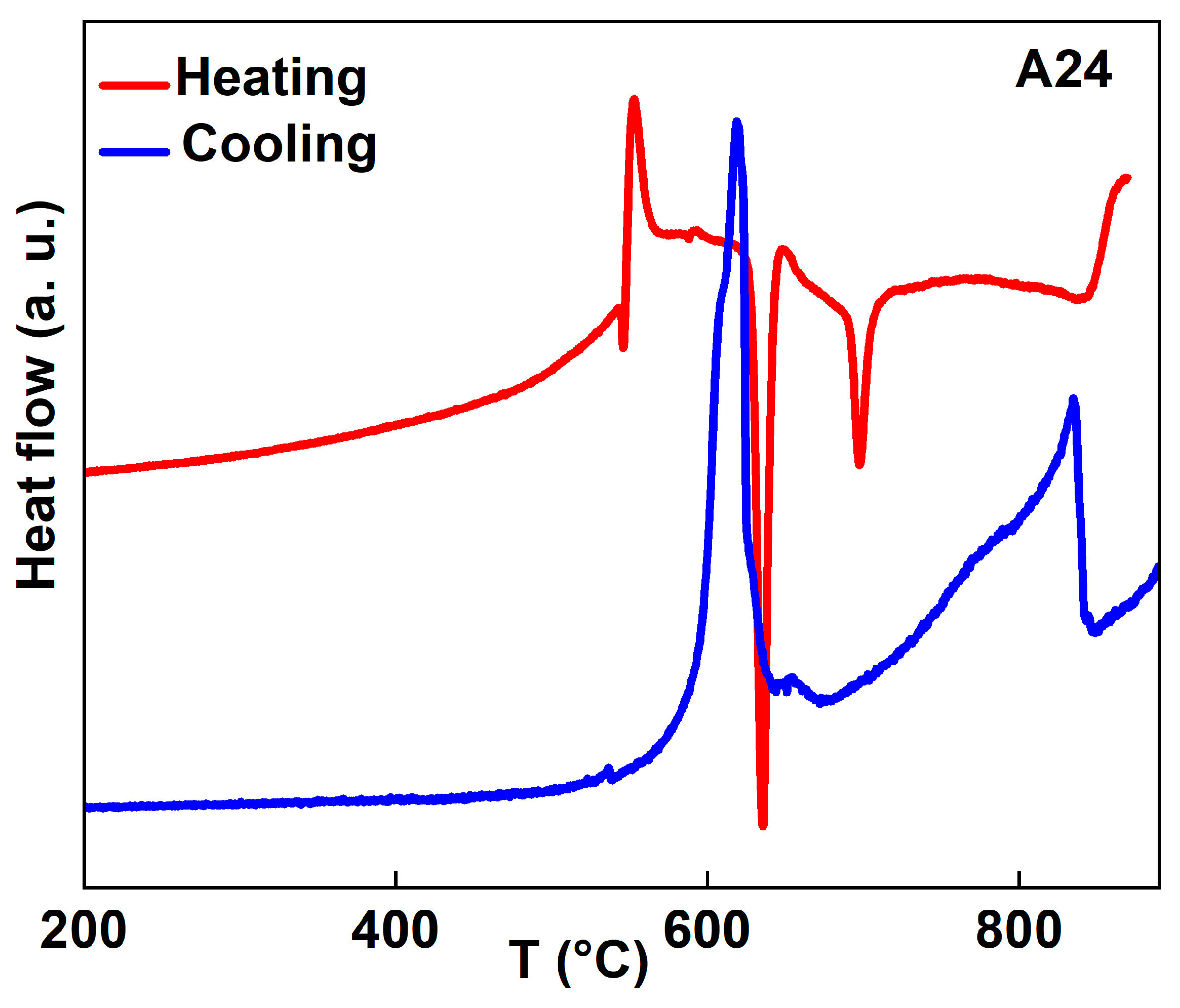
3.2. Heat-Treated Powders

The thermal stability of the A24 powder was studied in the temperature range of 25–900 °C upon heating and cooling at a rate of 10 °C/min under an argon atmosphere. Usually, the phase nucleation, or precipitate dissolution, is characterised by a heat flow peak over the temperature range of the corresponding reaction. Consequently, the coexistence of several exothermic and endothermic peaks in the 400–900 °C range in the heating and cooling DSC curves (Figure 7) can be related to recovery, strain relaxation, melting, recrystallisation, and phase transformations. Those peaks confirm the heterogeneity of the ball-milled powders, as revealed by XRD, through the presence of a mixture of A, Cu, and Mn solid solutions.
The exothermic peaks that appear during heating at approximately 542.5 and 552.5 °C can be attributed to the precipitation, solid-state transformation, and formation of the Al20Cu2Mn3 T-phase, which releases heat. The temperature of the sharp endothermic peak at approximately 635.9 °C, which is lower than pure Al (660 °C), is associated with melting the Al-rich solid solution, confirming the alloying of Al with Mn and Cu. α-Mn is known to be stable up to about 700 °C [48] and transforms upon heating beyond this temperature. Therefore, the endothermic peak at ~697.4 °C might be related to the transformation of the α-Mn phase from the complex α-Mn body-centred cubic (bcc) structure to the primitive β-Mn cubic structure. At the same time, the endothermic peak at ~844 °C can be attributed to the melting of the Cu solid solution formed by alloying Mn and Al with Cu, as this temperature is lower by about 186 °C from the melting point of Cu, which is ~1030 °C.
During cooling, the asymmetrical shape of the exothermic peaks in the temperature domain of 600–850 °C indicates the presence of two overlapping thermal events for each peak at approximately 620 °C and 609.4 °C, and 830 °C and 780 °C, which can be associated with the recrystallisation of the Al solid solution and the precipitation of the Al20Cu2Mn3 T-phase [14] through nucleation and diffusion-controlled growth during solidification from the melt, particularly for a high Mn content, which is key in promoting this phase. According to the ternary Al-Cu-Mn alloy system [49], the mixture of Al + Al20Cu2Mn3 forms either from the mix of liquid + Al6Mn at 616 °C through the reaction L + A l 6 M n 616 ° C A l + A l 20 C u 2 M n 3 , where the concentrations of Cu and Mn in the liquid phase are about 14.8 and 0.9, respectively, or directly from the melt at the eutectic alongside Al in the temperature range 616–547 °C ( L 616 547 ° C A l + A l 20 C u 2 M n 3 ). The ternary Al20Cu2Mn3 intermetallic (T-phase) contains up to 15.3% Cu and 19.8% Mn within the concentration range of 12.8–19% Cu and 19.8–24% Mn [49].
The crystal structure of the A24_900 °C powders after cooling to RT was analysed by XRD. The displayed diffractogram in Figure 8 shows sharp Bragg peaks with increased intensities and the appearance of new diffraction peaks, suggesting the formation of a new structure and significantly reduced milling-induced defects. These results confirm that the thermal treatment has a strong influence on the alloys’ microstructures, particularly in terms of the crystallite size and the degree of crystalline order. The structural refinement of A24_900 °C after cooling to RT (Table 3) reveals the formation of a nanocomposite structure where NC Al20Cu2Mn3 precipitates (37 nm) are dispersed into the Al matrix (62 nm). The reduction in the crystallite size can be attributed to the recrystallisation process.
The Al20Cu2Mn3 alloy is denoted as the T-phase, having a Bbmm space group (No. 63), with lattice parameters a = 24.2 Å, b = 12.5 Å, and c = 7.72 Å, featuring several inequivalent Al sites and defined Cu and Mn positions [50]. The structural model of the Al20Cu2Mn3 phase has been derived from the well-known structure of the ternary Al60Mn11Ni4 phase (PDF file 1901467) since they show a remarkable resemblance. The Al, Mn, and Cu atoms occupy the following 156 positions: Al (16h, 8g, 8f, 4c), Cu (8f, 4c), and Mn (8f, 8g, 4c). The weight fraction of the T-phase is about 27.7%. The atomic parameters of the Al20Cu2Mn3 phase are gathered in Table 4. The formation of the Al20Cu2Mn3 intermetallic compound in the A24_900 °C powder can be related to the solubility enhancement. This finding agrees well with the Al-Cu-Mn phase diagram of the formation of the stable T-phase.
The decrease in the lattice parameter of Al to 4.0434 ± 10−4 Å can be related to the diffusion of Mn and Cu atoms into its crystal lattice. Additionally, the cell volume of the T-phase is reduced by approximately 2.41%.
Figure 9a shows the morphology of the A24_900 °C powder, which reveals the particle size and shape distributions. The punctual analysis indicates three types of particles with different elemental compositions. The dark grey particles (point 1) are attributed to the enriched Al(Mn, Cu) solid solution containing 2.27 wt. % Mn and 3.29 wt. % Cu. The dirty white particles (point 2) with 75.22 wt. % Al, 22.73 wt. % Mn, and 2.05 wt. % Cu can be related to the Mn-enriched Al(Mn, Cu) solid solution, while the white particles (points 3 and 4) with approximately 78 wt. % Al, 14 wt. % Mn, and 8 wt. % Cu can be linked to the Al20Cu2Mn3 T-phase, thus confirming the XRD results. These observations are also confirmed by the elemental EDS map (Figure 9b), which shows the presence of the Al-enriched matrix constituting 72% of the investigated area and 28% related to a Mn/Cu-rich T-phase, in agreement with the phase’s weight fraction from the XRD data. This indicates solid solution decomposition and the formation of a thermodynamically stable intermetallic. One also notes that Cu is more homogeneously distributed in the Al matrix than Mn, which is localised mainly in the T-phase region (point 2).

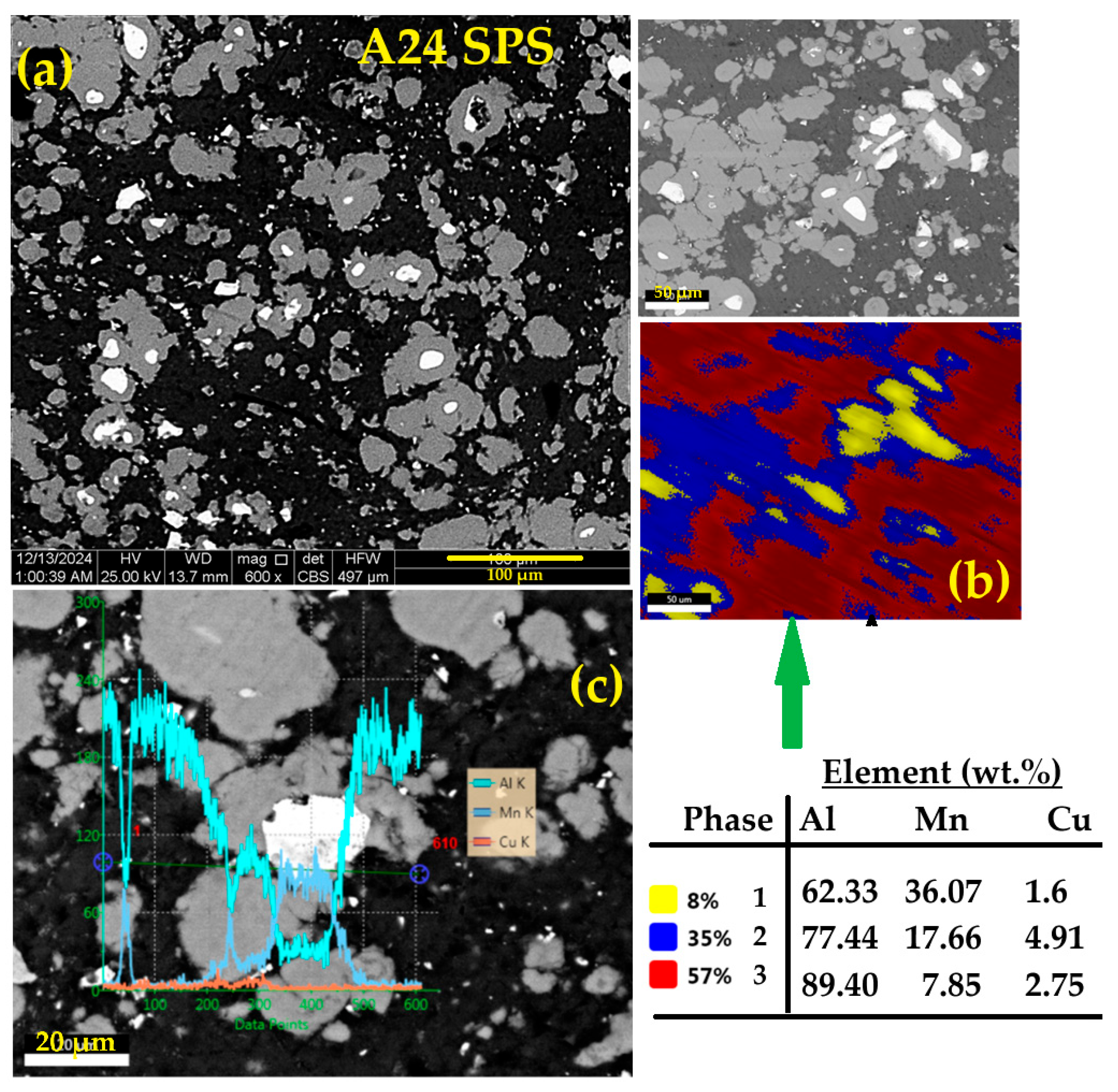
3.3. Sintered Powders

3.3.1. Structural Analysis

During the heating of mechanically alloyed powders, processes such as recovery, recrystallisation, grain growth, and decomposition of the supersaturated solid solution can occur, along with the precipitation of secondary phases. Sintering at 500 °C for 1 h (A24S) results in partial recovery, as indicated by the sharpening and increased intensity of the diffraction peaks (Figure 10).
The crystal structure refinement of the A24S sample was performed with four phases: FCC Al solid solution, orthorhombic Al6Mn (space group Ccmm No. 63, a = 6.4978 Å, b = 7.5518 Å, and c = 8.8703 Å), tetragonal Al2Cu known as the θ-phase in the Al-Cu binary phase diagram (space group I4/mcm No. 140, lattice parameters a = b = 6.067 Å, and c = 4.877 Å), and orthorhombic Al20Cu2Mn3. The refined lattice parameters, average crystallite size, and weight fractions are gathered in Table 5. The sintering temperature (500 °C) is appropriately high to activate the diffusion of Cu and Mn atoms, enabling the nucleation and growth of the intermetallic phases. Due to the limited solid solubility of Mn and Cu in Al at RT, Mn and Cu tend to precipitate as stable Al6Mn and Al2Cu intermetallic dispersoids during sintering. The Al6Mn phase is thermodynamically favoured in Al-rich alloys with an adequate Mn content and reduces the supersaturation of Mn in the Al matrix upon its formation. Similarly, the precipitation of Al2Cu reduces the Cu content in the solid solution, contributing to the mechanical strengthening mechanism [51]. The Al20Cu2Mn3 T-phase forms through the combined segregation and reaction of Cu and Mn atoms in the Al matrix during sintering. The T-phase, known for its thermal stability and increase in heat resistance of the alloy [52,53,54], precipitates through the decomposition of the supersaturated Al solid solution enriched in Cu and Mn during sintering. The same phases were identified by Yakovtseva et al. in a cast Al-14.3 Mn-6.5 Cu (in wt. %) alloy after solidification, followed by annealing at 520 °C for 24 h, confirming the presence of the Al solid solution, Al6Mn, Al2Cu, and the T-phase (Al20Cu2Mn3) [7,14].
Compared to the A24 powders, the crystallite size of the Al matrix increases to 394 nm, its lattice parameter remains nearly constant at 4.0481 ± 10−4 Å, and the weight fraction declines slightly to 70.5%. The Al2Cu and T-phase show reduced cell volumes of −0.05% and −1.41%, respectively, while that of the Al6Mn increases by 2.3%. The crystallite size of the intermetallics ranges between 99 and 202 nm. The weight fractions of the T-phase, Al6Mn, and Al2Cu are 18.5, 3.6, and 7.4%, respectively. The fractional atomic coordinates (x, y, z) and atom site occupancy of the Al20Cu2Mn3 phase are given in Table 6. Several Al (2, 4, 7, 8, 11, and 13) and Cu (1 and 2) atom sites exhibit lower occupancies, confirming the presence of crystal defects, cell volume reduction, and lattice shrinkage. Additionally, the atomic positions deviate slightly upon sintering.
The crystal structure of the consolidated powders produced by SPS (A24SPS) exhibits a mixture of the Al solid solution, T-phase, Al6Mn, and α-Mn, as shown in Figure 11. The disappearance of the Al2Cu phase aligns with thermal treatment studies, which suggest that temperatures around 400–450 °C promote the dissolution of Al2Cu (θ-phase) and the subsequent precipitation of the T-phase, driven by increased atomic diffusion and Cu enrichment within the Al matrix [7]. The presence of the α-Mn phase alongside the Al6Mn and Al20Cu2Mn3 phases is due to the higher Mn content in the produced alloy. The precipitation of the T-phase is favoured by the presence of about a 1.5–2 wt. % Mn content and Cu content around 1–2 wt. %. Once formed, the T-phase remains stable during heat treatments and significantly influences the final properties of Al alloys. The Cu content plays a role in stabilising the T-phase alongside Mn [55]. It contributes to dispersion strengthening by hindering dislocation motion, pinning grain boundaries, and promoting homogeneous deformation [52,53,54].
As shown in Table 7, the lattice parameter, crystallite size, and weight fraction of the Al solid solution are reduced compared to those of the A24S pellet. The T-phase’s cell volume and crystallite size decrease, while its weight fraction increases. Additionally, the cell volume of the Al6Mn and the weight fraction increase. Those changes can be ascribed to the SPS process. Eight atom site occupancies (Al1, Al5, Al6, Al12, Al13, Cu1, Cu2, and Mn3) show reduced values in the Al20Cu2Mn3 T-phase (Table 8), confirming the reduced cell volume. The weight fraction of the α-Mn precipitates is about 5.7%.
The complex interplay of Mn/Cu diffusion into the Al matrix, solid-state reactions, and thermal processes leads to the precipitation of the Al6Mn and T-phase phases after conventional (A24S) and SPS (A24SPS) sintering. However, the Al2Cu phase is observed in the A24S, and the remaining α-Mn in the A24SPS samples. The formation of Al2Cu and Al6Mn phases can be related to the increases in solute supersaturation and defect density (dislocations, grain boundaries, and vacancies), which lead to enhanced diffusion and nucleation. The increase in the system’s internal energy promotes atomic diffusion at relatively low temperatures, facilitating phase transformations and the precipitation of intermetallics during milling. The dissolution of Mn and the precipitation of the Al6Mn phase during milling were observed in the ball-milled Al–Mn powders after 70 h [56]. The formation of the Al2Cu phase during milling [57] was attributed to the negative mixing enthalpy of the Al–Cu system. A mixture of FCC-Al and tetragonal Al2Cu phases, corresponding to a composition of 20 at. %Cu, according to the equilibrium phase diagram of the Al–Cu system, was obtained after 20 h of milling [58].

3.3.2. Morphology

The alloy’s microstructure after different consolidation processes (A24S and A24SPS) reveals distinct morphological and compositional evolutions. The SEM-EDS analyses of the A24S sample (Figure 12) indicate a heterogeneous distribution of the Al, Mn, and Cu elements into four distinct areas related to (i) an Al-enriched matrix (red area) containing 95 wt. % Al, 2.56 wt. % Mn, and 2.07 wt. % Cu; (ii) Al/Mn/Cu (yellow area), with ~70wt. % Al, ~22 wt. % Mn, and ~8 wt. % Cu; (iii) Cu-enriched Cu-Al (blue area) formed by about 85 wt. % Cu and 15 wt. % Al; and (iv) Mn-enriched Mn-Al (green area) containing approximately 75 wt. % Mn and 24 wt. % Al. Based on the XRD results, the four areas can be related to the formation of the Al solid solution (red area), intermetallic Al20Cu2Mn3 T-phase (yellow area), Al6Mn (green area), and Al2Cu (blue area), representing 76, 17, 2, and 16%, respectively, of the total area. The EDS mapping analysis reveals an Al-based (86.65 wt. %) matrix containing 6.7 wt. % Mn and 6.65 wt. % Cu.
The punctual analysis (inset in Figure 12) reveals that the white small precipitates (area 1) are Mn-enriched Mn-Al, the dark grey area is related to the Al solid solution (point 4), and the T-phase forms the grey area (points 2 and 3). On average, the EDS analysis of the total area (mapping) indicates that it consists of 86.65 wt. % Al, 6.7 wt. % Mn, and 6.5 wt. % Cu.
The morphology of the consolidated powders by SPS (A24SPS) (Figure 13a) reveals the existence of (i) a dark region related to the Al-enriched matrix, (ii) grey particles with a size distribution related to the Al20Cu2Mn3 intermetallic T-phase, and (iii) dispersed smaller white particles attributable to the Al6Mn phase according to the XRD results. The EDS map (Figure 13b) shows the presence of Al/Mn-rich particles containing 62.33 wt. % Al and 36.07 wt. % Mn (yellow colour); Al/Mn/Cu particles with 77.44 wt. % Al, 17.66 wt. % Mn, and 4.91 wt. % Cu (blue colour); and an Al-enriched (89.4 wt. %) solid solution with 7.85 wt. % Mn and 2.75 wt. % Cu (red colour), representing 8, 35, and 57 wt. % of the observed area. Those observations confirm the XRD results. The line profile analysis (Figure 13c) confirms the results of the SEM image and EDS mapping.

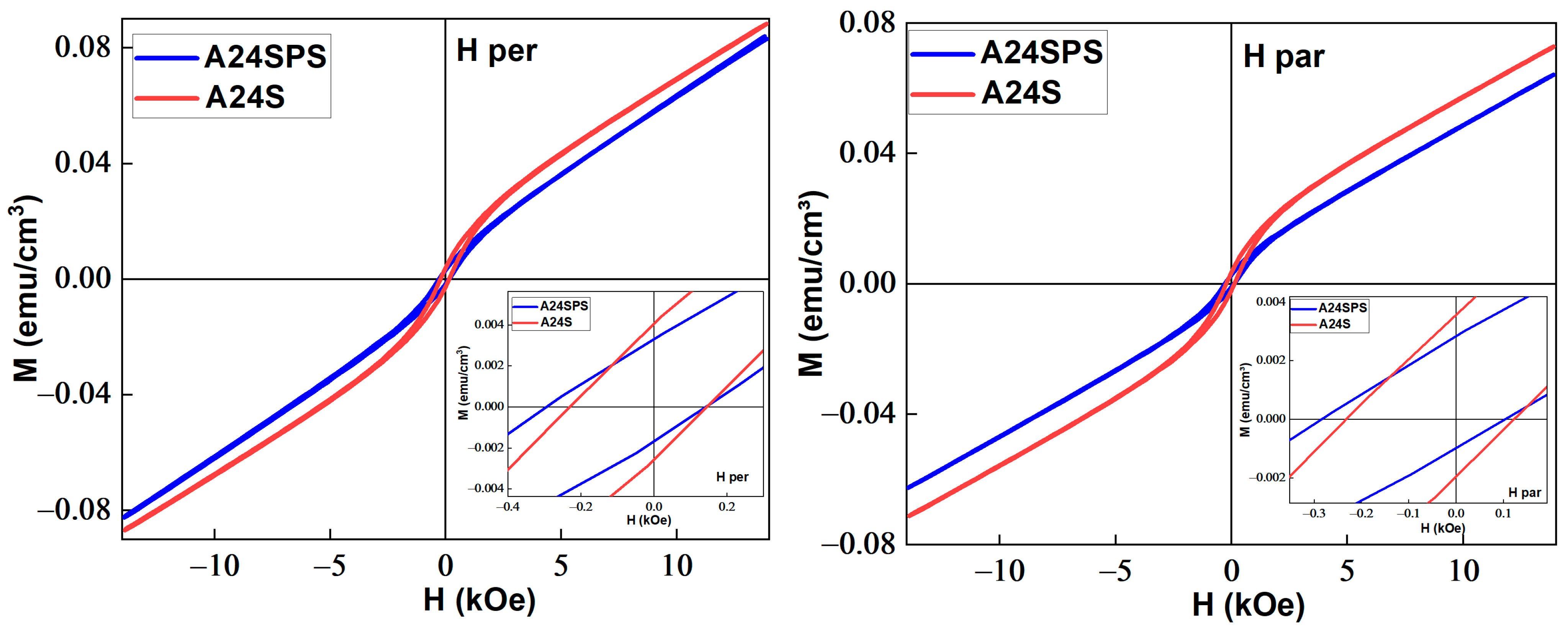
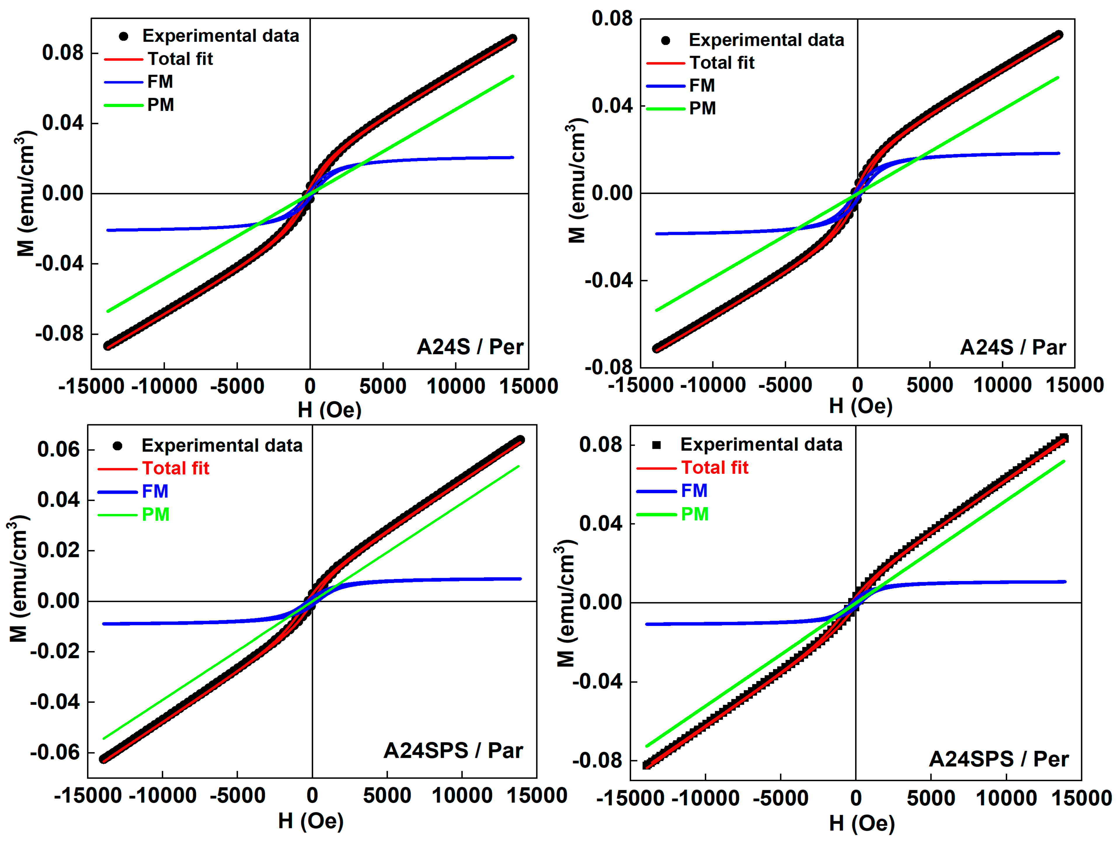
3.3.3. Magnetic Properties

The hysteresis cycles of the sintered A24S and A24SPS samples as a function of the applied magnetic field in parallel (Par) and perpendicular (Per) directions are shown in Figure 14. The insets show the zoomed-in information in the low field. The hysteresis loops are nearly identical for both samples. The change in the shape of the hysteresis loops after sintering may be due to several factors, including the formation of intermetallic phases through the reorganisation of atoms.
The shape and non-saturation of the M(H) curves suggest the coexistence of paramagnetic/antiferromagnetic (PM/AFM) contributions to the M-H curves along with that of the ferromagnetic (FM) contribution. The theoretically intrinsic FM parameters, such as Ms, Hc, and Mr, can be extracted by subtracting the PM/AFM contribution from the experimental M(H) curve (Figure 15) using the succeeding fitting function [40]:
M H = 2 M s π t a n 1 H ± H c H c t a n π × M r 2 × M s + χ H
The first term represents the FM hysteresis curve, and the second term is a linear contribution related to a possible AFM contribution due to the presence of MnAl solid solutions. The fitting results are gathered in Table 9. The difference in the percentage of the FM contribution, which represents ~14.5% in the A24SPS and ~26.5% in the A24S samples, might be related to the weight fractions of FM precipitates.
The coercive field increases after sintering to about 141–187 Oe for the A24S and to 276–315 Oe for the A24SPS. Similarly, the EB increases to 187–216 Oe for the A24S, and to 323–391 Oe for the A24SPS. The increase in both Hc and EB can be attributed to the microstructural changes that occur during the sintering process. Indeed, the sintering process leads to an increase in crystallite size, thereby reducing structural defects, as well as strains and porosity. The increase in the effective interfacial area where exchange coupling occurs leads to the rise in EB strength. Furthermore, the precipitation of intermetallic phases may contribute to the upsurge in both Hc and EB. The microstructural changes mutually strengthen the interfacial exchange coupling responsible for the EB effect. According to the Mr/Ms ratio, the A24S falls into the MD category, while the A24SPS falls into pseudo-single domains (PSD) [59].

3.4. Mechanical Properties

Microindentation testing is a valuable technique for assessing small-scale mechanical properties, offering insights into hardness, the elastic modulus, plasticity, and related characteristics. The method involves applying a load with a sharp indenter (typically diamond-tipped) and measuring the resulting penetration depth over time. The mechanical properties of the A0, A3, A6, A24, A24S, and A24SPS pellets were studied using microindentation tests with a 1 N load and a 15 s dwell time. At least ten measurement trials were performed for each sample, and the values were averaged.
The Vickers microhardness values of the A24 pellet increases to 68 HV, compared to the initial powder mixture (A0), which has a value of 44 HV. The increase in the microhardness values can be attributed to the crystallite size refinement, which significantly contributes to strengthening mechanisms. Smaller crystallites introduce a higher density of grain boundaries, which act as barriers to dislocation motion, thereby increasing the material’s hardness. In addition, changes in microhardness can also be influenced by microstructural inhomogeneities, structural hardening, and lattice distortions.
Hardening at elevated temperatures is primarily achieved through precipitation hardening, facilitated by the formation of Al20Cu2Mn3 dispersoids and θ-phase (Al2Cu) precipitates. The Mn-rich phase forms at higher temperatures and exhibits greater thermal stability than Al2Cu, making it the principal contributor to the alloy’s high-temperature performance. However, due to the low solubility limit of Mn into the Al lattice, conventional processing methods do not produce a sufficiently high density of Al20Cu2Mn3 precipitates [20]. Due to grain refinement, metals sintered from milled powders are typically stronger and harder than those sintered from as-received powders. However, this improvement in strength and hardness often comes at the cost of reduced ductility [60,61]. After conventional sintering (A24S), the microhardness increases to about 80 HV. The simultaneous presence of Al2Cu (θ phase, strengthening), Al6Mn, and the T-phase initiates a dispersion strengthening effect, although partial coalescence and grain growth limit the reinforcement. In contrast, after SPS sintering (A24SPS), the dissolution of the Al2Cu phase and its disappearance contribute to a massive precipitation of the T-phase (31.51%), along with Al6Mn (11.67%) and the Al matrix (51.13%). The XRD results confirm this evolution. Grain refinement, homogeneous dispersion of hard phases, and T-phase stability strongly contribute to the mechanical strength, as reflected in a maximum microhardness of 581 HV. SEM observations support this interpretation, showing very dense and well-consolidated regions. Thus, the combination of SEM, XRD, and microhardness data highlight that the reduction in crystallite size, the homogeneity of intermetallic phase distribution, and the formation of T-phase via SPS are the key factors responsible for the significant increase in the alloy’s hardness. The maximum hardness value of 581 HV, which is relatively high for Al alloys, may contribute to a longer service life and improved performance under cyclic loading and wear conditions. This high value enables the Al–16 wt. % Mn–7 wt. % Cu alloy to be a competitive candidate against other high-strength Al alloys, especially where wear resistance is crucial. These findings are consistent with the previous study by Soares et al., who reported that grain refinement and increased dislocation density induced through severe plastic deformation significantly enhance the hardness and strength of Al-based alloys after consolidation processes [24].
Yakovtseva et al. reported a significant increase in the microhardness of the as-cast Al-18% Mn-8% Cu alloy through high-energy ball milling to a maximum value of 316 ± 9 HV, and 330 ± 15 HV for the alloy reinforced with diamond nanoparticles [62]. High-energy ball milling of the as-cast Al-15.3% Mn-6.2% Cu alloy significantly increased microhardness from 132 HV to 500–520 HV with Al2O3 reinforcement after 2.5 h. A drop to ~300 HV occurred at 5 h, followed by partial re-hardening (up to ~400 HV) in Al2O3-containing composites due to Al6Mn precipitation. Al2O3 addition enhanced both early-stage and long-term hardening behaviour [14]. Zhang et al. studied Al matrix composites reinforced with amorphous CuZrAl particles produced by MA and SPS. The Al20 sample displayed impressive mechanical properties, including a yield strength of 408 MPa, a fracture strength of 459 MPa, and a microhardness of 290 HV. These properties were attributed to the reinforcement from secondary phases, high densification, grain refinement, and strong bonding between the matrix and the reinforcement [63,64].

4. Conclusions

The microstructural, structural, thermal, magnetic, and mechanical properties of the mechanically alloyed and consolidated Al–16 wt. % Mn–7 wt. % Cu powders were studied using XRD, SEM, EDS, DSC, VSM, and a microhardness tester. The obtained results are as follows:
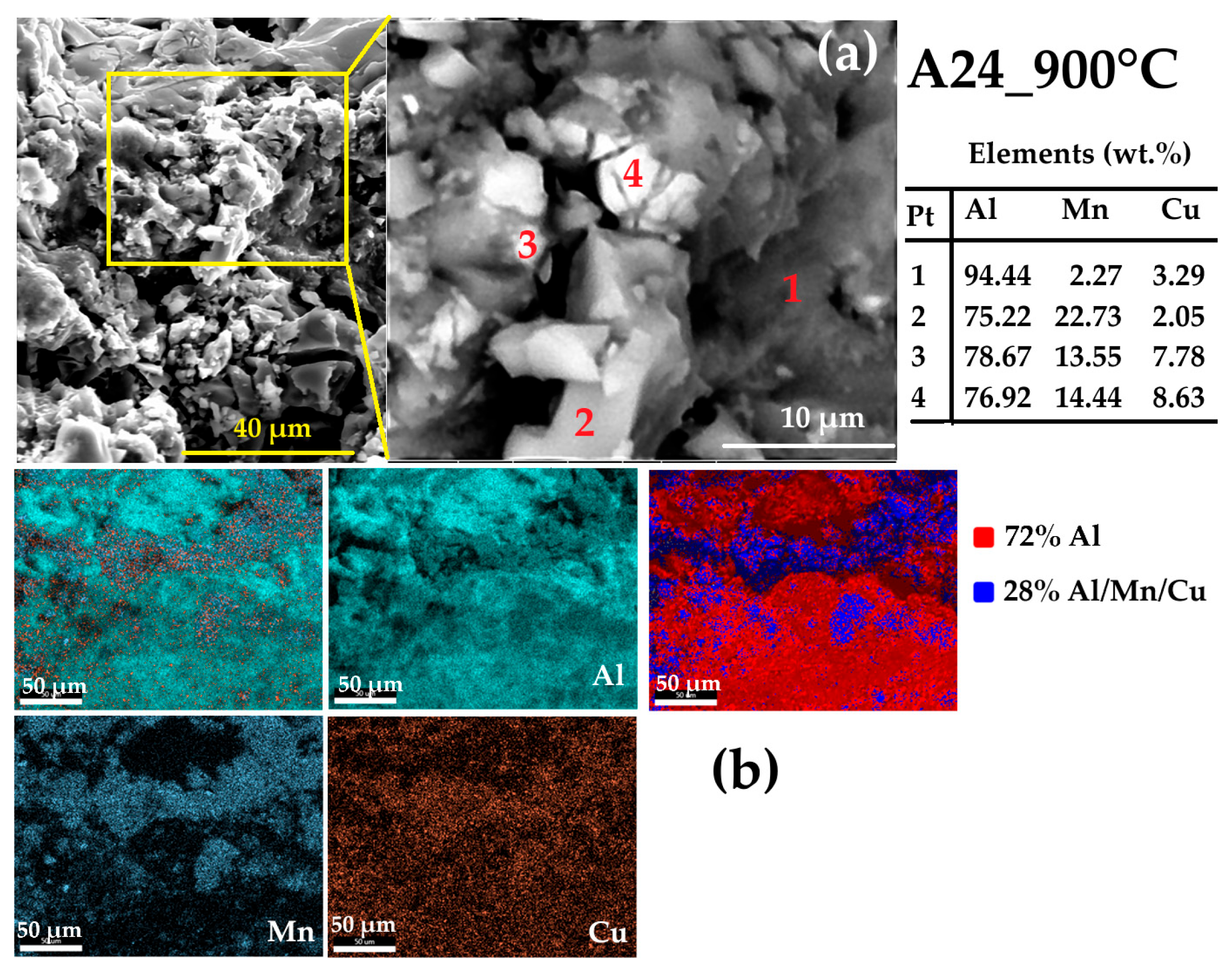
  • The milling process, up to 24 h (A24), refines the microstructure and forms a nanocomposite structure where nanosized Mn (77 nm, 17.55%) and Cu (62 nm, 11.25%) precipitates are dispersed within the Al matrix (175 nm, 71.2%). The EDS analysis reveals the presence of Cu-Al-, Mn-Al-, and Al-Mn-enriched particles.
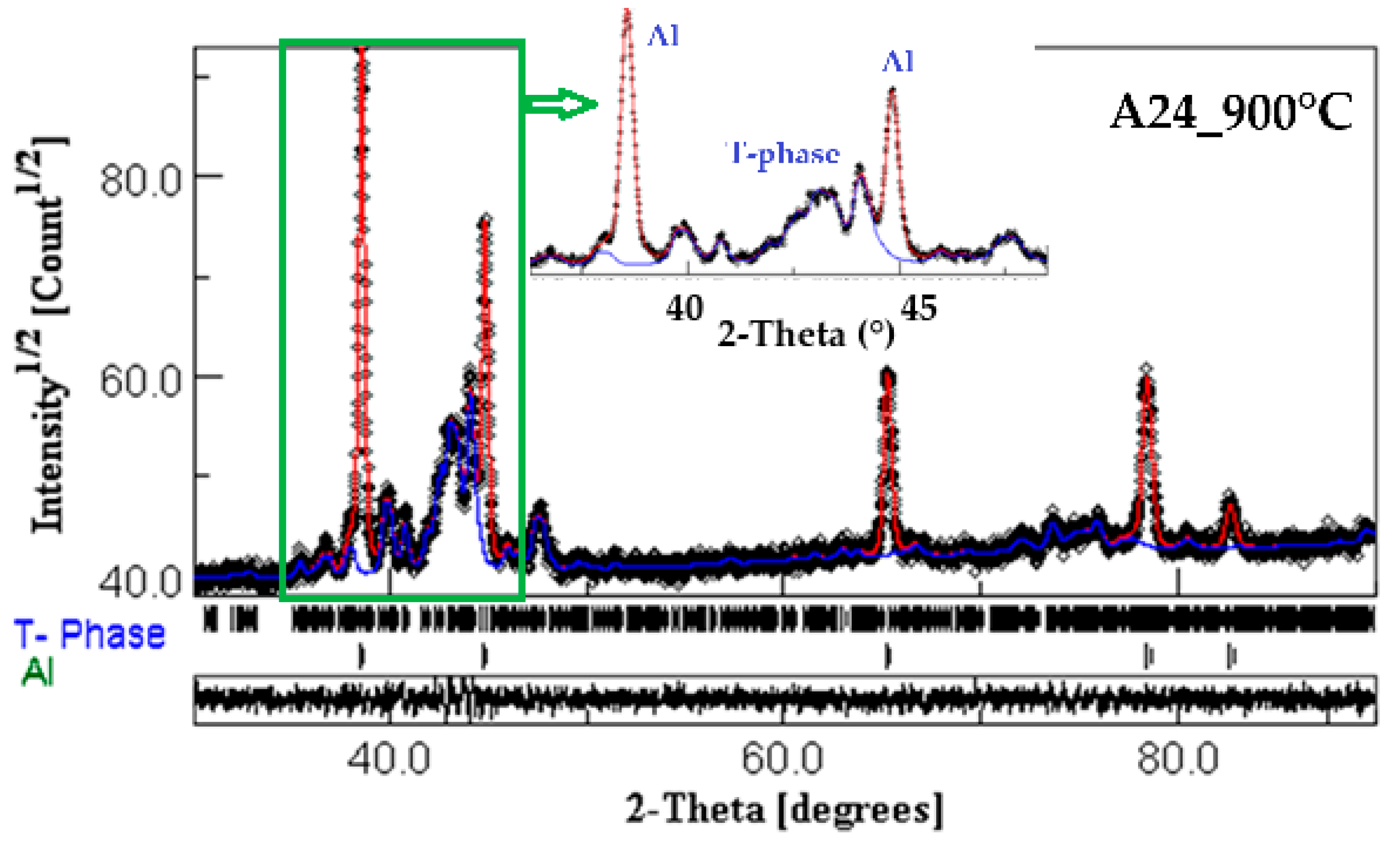
  • The presence of several exothermic and endothermic peaks in the DSC scans during heating and cooling indicates the occurrence of different phase transformations. The XRD analysis and EDS mapping of the heat-treated A24_900 °C powder reveal a nanocomposite structure where the intermetallic Al20Cu2Mn3 nanoprecipitates are dispersed into the Al matrix.
  • The milled powders exhibit a weak ferromagnetism with an EB behaviour. Hc reaches 101 Oe after 24 h of milling. The magnetisation increases and the EB drops with increasing milling time.
  • The fitted Ms values using the LAS are comparable to the experimental values.
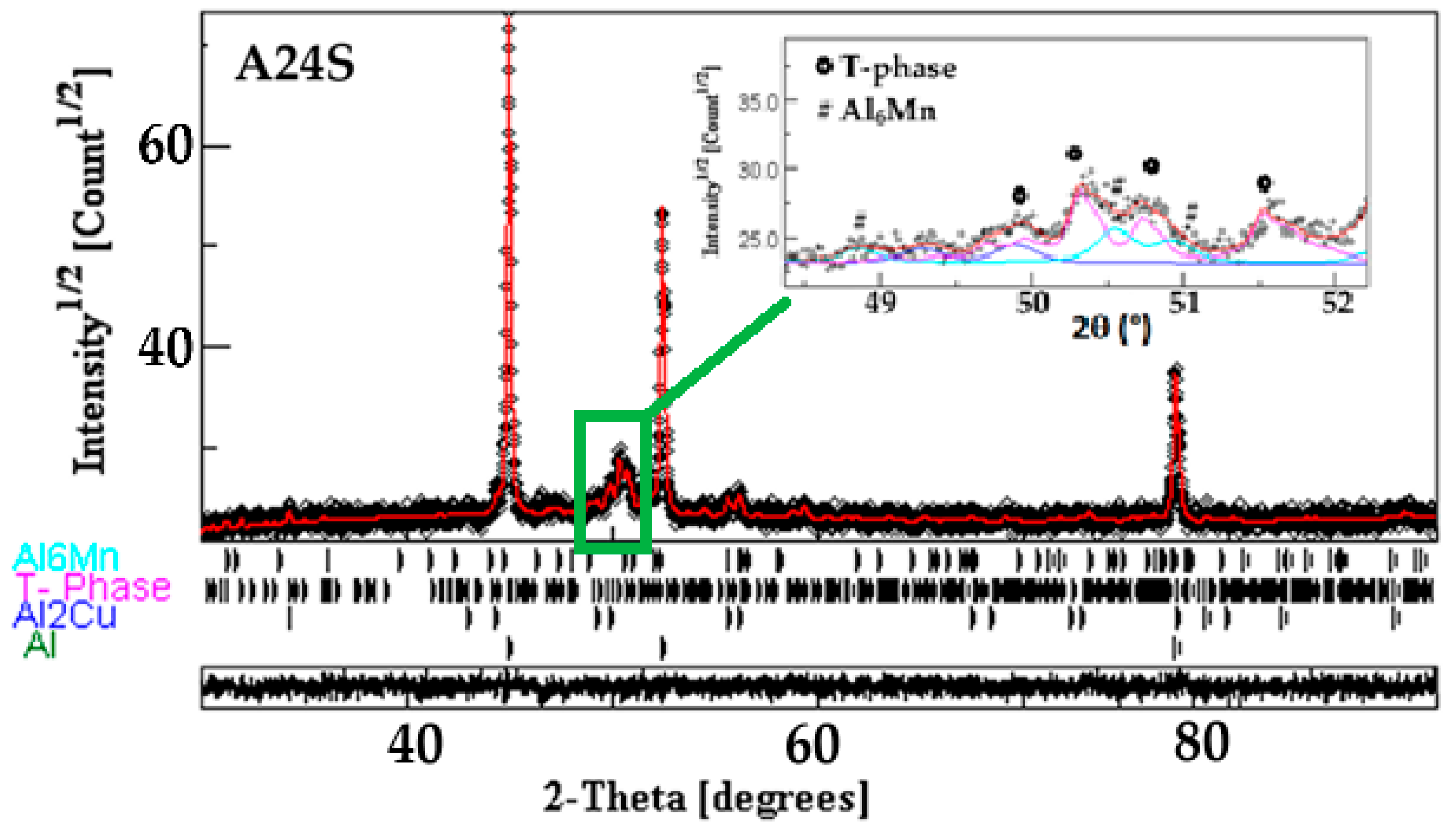
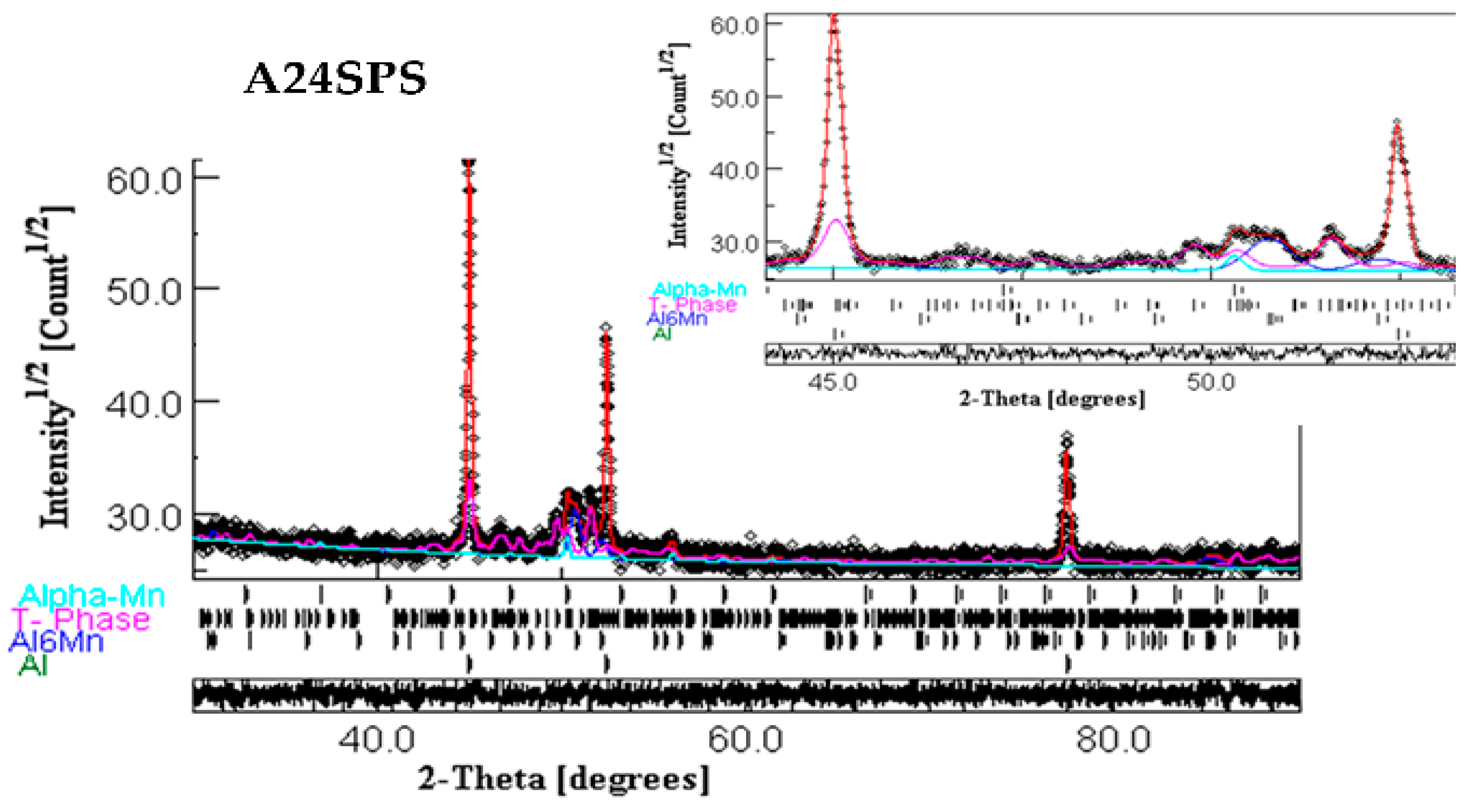
  • Conventional sintering of the A24 powder (A24S) at 500 °C for one hour leads to the precipitation of Al6Mn, Al2Cu, and Al20Cu2Mn3 T-phase into the Al-enriched matrix. In contrast, the crystal structure of the consolidated powders by SPS (A24SPS) consists of an Al solid solution, Al6Mn, T-phase, and α-Mn.
  • The heat treatment and sintering affect the lattice parameters (a, b, and c), cell volume, crystallite size, weight fraction, atom site occupancy, and fractional coordinates of the Al20Cu2Mn3 T-phase.
  • The sintered samples exhibit the coexistence of a significant PM/AFM contribution to the M-H curves, in addition to the FM contribution, with increasing Hc and decreasing EB.
  • A higher microhardness value of about 581 HV is achieved for the A24SPS sample compared to those of the A24 (68 HV) and A24S (80 HV) samples. The improvement in microhardness can be related to the decrease in the T-phase’s crystallite size and the increase in its weight fraction.

Author Contributions

Conceptualization, A.S.B. and S.A.; methodology, A.S.B. and S.A.; software, A.S.B. and S.A.; validation, S.A. and J.J.S.; formal analyses, A.S.B., A.B., H.H. and S.A.; investigation, A.S.B. and H.H.; resources, S.A.; data curation, S.A.; writing—original draft preparation, A.S.B.; writing—review and editing, S.A.; visualisation, S.A. and A.B.; supervision, S.A. and J.J.S.; project administration, S.A. and J.J.S. All authors have read and agreed to the published version of the manuscript.

Funding

This research received no external funding.

Institutional Review Board Statement

Not applicable.

Informed Consent Statement

Not applicable.

Data Availability Statement

The data presented in this study are available upon request from the corresponding author.

Acknowledgments

The Directorate-General for Scientific Research and Technological Development (DGRSDT), MESRS, Algeria, provided financial support. The authors thank Foued KHAMMACI from the LM2S Laboratory for the XRD, VSM, and DSC measurements. The ENSTI-Annaba is acknowledged for the SEM observations.

Conflicts of Interest

The authors declare no conflicts of interest.

References

  1. Torralba, J.D.; Da Costa, C.; Velasco, F. P/M aluminum matrix composites: An overview. J. Mater. Process. Technol. 2003, 133, 203–206. [Google Scholar] [CrossRef]
  2. Ramanathan, A.; Krishnan, P.K.; Muraliraja, R. A review on the production of metal matrix composites through stir casting—Furnace design, properties, challenges, and research opportunities. J. Manuf. Process. 2019, 42, 213–245. [Google Scholar] [CrossRef]
  3. Ravikumar, K.S.; Ghanaraja, S.; Ramesh, M.R. Synthesis and characterization of nano-alumina powder by milling of Al and MnO2 powder mixture. Mater. Today Proc. 2021, 46, 9021–9026. [Google Scholar] [CrossRef]
  4. Nokhrin, A.; Malekhonova, N.; Chuvil’deev, V.; Melekhin, N.; Bragov, A.; Filippov, A.; Boldin, M.; Lantsev, E.; Sakharov, N. Effect of High-Energy Ball Milling Time on the Density and Mechanical Properties of W-7%Ni-3%Fe Alloy. Metals 2023, 13, 1432. [Google Scholar] [CrossRef]
  5. Wei, L.K.; Abd Rahim, S.Z.; Al Bakri Abdullah, M.M.; Yin, A.T.M.; Ghazali, M.F.; Omar, M.F.; Nemes, O.; Sandu, A.V.; Vizureanu, P.; Abdellah, A.E. Producing Metal Powder from Machining Chips Using Ball Milling Process: A Review. Materials 2023, 16, 4635. [Google Scholar] [CrossRef]
  6. Nayak, K.; Han, J.; Jung, C.; Joo, M.; Lee, K.; Bae, D.; Choi, H. Synergetic effect of milling speed and duration on particle morphology and mechanical properties of nanocrystalline Al matrix containing SiC. Powder Metall. 2023, 66, 519–529. [Google Scholar] [CrossRef]
  7. Yakovtseva, O.A.; Emelina, N.B.; Mochugovskiy, A.G.; Tabachkova, N.Y.; Prosviryakov, A.S.; Mikhaylovskaya, A.V. Influence of Pre-Milling on the Mn Solid Solubility in the Al-Mn-Cu Alloy during Mechanical Alloying. Metals 2023, 13, 756. [Google Scholar] [CrossRef]
  8. Prosviryakov, A.; Shcherbachev, K.; Tabachkova, N.Y. Investigation of nanostructured Al-10 wt. % Zr material prepared by ball milling for high temperature applications. Mater. Charact. 2017, 123, 173–177. [Google Scholar] [CrossRef]
  9. Suryanarayana, C. Mechanical alloying: A novel technique to synthesize advanced materials. Research 2019, 2019, 4219812. [Google Scholar] [CrossRef]
  10. Esquivel, J.; Murdoch, H.; Darling, K.; Gupta, R. Excellent corrosion resistance and hardness in Al alloys by extended solid solubility and nanocrystalline structure. Mater. Res. Lett. 2018, 6, 79–83. [Google Scholar] [CrossRef]
  11. Suryanarayana, C. Mechanical alloying and milling. Prog. Mater. Sci. 2001, 46, 1–184. [Google Scholar] [CrossRef]
  12. Li, Y.; Hu, A.; Fu, Y.; Liu, S.; Shen, W.; Hu, H.; Nie, X. Al Alloys and Casting Processes for Induction Motor Applications in Battery-Powered Electric Vehicles: A Review. Metals 2022, 12, 216. [Google Scholar] [CrossRef]
  13. Murashkin, M.Y.; Sabirov, I.; Sauvage, X.; Valiev, R.Z. Nanostructured Al and Cu alloys with superior strength and electrical conductivity. J. Mater. Sci. 2015, 51, 33–49. [Google Scholar] [CrossRef]
  14. Yakovtseva, O.A.; Bazlov, A.I.; Prosviryakov, A.S.; Emelina, N.B.; Tabachkova, N.Y.; Mikhaylovskaya, A.V. The influence of the Al2O3 particles on the microstructure of the mechanically alloyed Al-Mn-Cu alloy. J. Alloys Compd. 2023, 930, 167452. [Google Scholar] [CrossRef]
  15. Darling, K.A.; Roberts, A.J.; Armstrong, L.; Kapoor, D.; Tschopp, M.A.; Kecskes, L.J.; Mathaudhu, S.N. Influence of Mn solute content on grain size reduction and improved strength in mechanically alloyed Al–Mn alloys. Mater. Sci. Eng. A 2014, 589, 57–65. [Google Scholar] [CrossRef]
  16. Ruan, S.; Schuh, C.A. Electrodeposited Al–Mn alloys with microcrystalline, nanocrystalline, amorphous and nano-quasicrystalline structures. Acta Mater. 2009, 57, 3810–3822. [Google Scholar] [CrossRef]
  17. Mochugovskiy, A.G.; Tabachkova, N.Y.; Mikhaylovskaya, A.V. Nanodispersoids of the quasicrystalline I-phase in Mn- and Mg-bearing aluminum-based alloys. Mater. Lett. 2021, 284, 128945. [Google Scholar] [CrossRef]
  18. Li, Y.J.; Zhang, W.Z.; Marthinsen, K. Precipitation crystallography of plate-shaped Al6(Mn, Fe) dispersoids in AA5182 alloy. Acta Mater. 2012, 60, 5963–5974. [Google Scholar] [CrossRef]
  19. Asgar-Khan, M.; Medraj, M. Thermodynamic Description of the Mg-Mn, Al-Mn and Mg-Al-Mn Systems Using the Modified Quasichemical Model for the Liquid Phases. Mater. Trans. 2009, 50, 1113–1122. [Google Scholar] [CrossRef]
  20. Darling, K.A.; Roberts, A.J.; Catalano, J.E.; Tschopp, M.A.; Kecskes, L.J. Effect of Processing Parameters on the Microstructure of Mechanically Alloyed Nanostructured Al-Mn Alloys. In Advanced Composites for Aerospace, Marine, and Land Applications II; Springer: Cham, Switzerland, 2016; pp. 3–11. [Google Scholar] [CrossRef]
  21. Taha, M.A.; Zawrah, M.; Abomostafa, H. Fabrication of Al/Al2O3/SiC/graphene hybrid nanocomposites from Al-dross by powder metallurgy: Sinterability, mechanical and electrical properties. Ceram. Int. 2022, 48, 20923–20932. [Google Scholar] [CrossRef]
  22. Fogagnolo, J.B.; Robert, M.H.; Torralba, J.M. Mechanically alloyed AlN particle-reinforced Al-6061 matrix composites: Powder processing, consolidation and mechanical strength and hardness of the as-extruded materials. Mater. Sci. Eng. A 2006, 426, 85–94. [Google Scholar] [CrossRef]
  23. Yakovtseva, O.A.; Mochugovskiy, A.G.; Prosviryakov, A.S.; Bazlov, A.I.; Emelina, N.B.; Mikhaylovskaya, A.V. The Microstructure and Properties of Al–Mn–Cu–Zr Alloy after High-Energy Ball Milling and Hot-Press Sintering. Metals 2024, 14, 310. [Google Scholar] [CrossRef]
  24. Soares, E.; Bouchonneau, N.; Alves, E.; Alves, K.; Araujo Filho, O.; Mesguich, D.; Chevallier, G.; Laurent, C.; Estournes, C. Microstructure and Mechanical Properties of AA7075 Aluminum Alloy Fabricated by Spark Plasma Sintering (SPS). Materials 2021, 14, 430. [Google Scholar] [CrossRef]
  25. Aliyu, I.; Saheb, N.; Hassan, S.; Al-Aqeeli, N. Microstructure and Properties of Spark Plasma Sintered Aluminum Containing 1 wt. % SiC Nanoparticles. Metals 2015, 5, 70–83. [Google Scholar] [CrossRef]
  26. Korznikova, G.F.; Nazarov, K.S.; Khisamov, R.K.; Sergeev, S.N.; Shayachmetov, R.U.; Khalikova, G.R.; Baimova, J.A.; Glezer, A.M.; Mulyukov, R.R. Intermetallic growth kinetics and microstructure evolution in Al-Cu-Al metal-matrix composite processed by high pressure torsion. Mater. Lett. 2019, 253, 412–415. [Google Scholar] [CrossRef]
  27. Belov, N.; Belov, V.; Alabin, A.; Mishurov, S. New generation of economically alloyed aluminum alloys. Metallurgist 2010, 54, 311–316. [Google Scholar] [CrossRef]
  28. Zhang, Y.; Zhou, Y.J.; Lin, J.P.; Chen, G.L.; Liaw, P.K. Solid-solution phase formation rules for multi-component alloys. Adv. Eng. Mater. 2008, 10, 534–538. [Google Scholar] [CrossRef]
  29. Takeuchi, A.; Inoue, A. Classification of bulk metallic glasses by atomic size difference, heat of mixing and period of constituent elements and its application to characterization of the main alloying element. Mater. Trans. 2005, 46, 2817–2829. [Google Scholar] [CrossRef]
  30. Lutterotti, L. MAUD Program Version 2.992. Available online: https://luttero.github.io/maud/ (accessed on 28 November 2021).
  31. Nam, S.W.; Lee, D.H. The effect of Mn on the mechanical behavior of Al alloys. Met. Mater. 2000, 6, 13–16. [Google Scholar] [CrossRef]
  32. Massalski, T.B.; Okamoto, H.; Subramanian, P.; Kacprzak, L.; Scott, W.W. Binary Alloy Phase Diagrams; American Society for Metals: Metals Park, OH, USA, 1986; pp. 106–107. [Google Scholar]
  33. Li, F.; Ishihara, K.; Shingu, P. The formation of metastable phases by mechanical alloying in the aluminum and copper system. Metall. Trans. A 1991, 22, 2849–2854. [Google Scholar] [CrossRef]
  34. Sivakova, A.; Karpov, A.; Busurina, M.; Lazarev, P.; Sytschev, G.; Morozov, Y.G.; Sytschev, A. Self-Propagating High-Temperature Synthesis of Cu–Mn–Al Alloys: Thermoelectric and Magnetic Properties. Int. J. Self-Propag. High-Temp Synth. 2024, 33, 237–244. [Google Scholar] [CrossRef]
  35. Boutabia, N.; Bouzabata, B.; Alleg, S.; Suñol, J.-J.; Greneche, J.-M. Mechanochemical reaction and phase transformations in the α-Fe2O3/Mg mixture. Mater. Chem. Phys. 2025, 337, 130570. [Google Scholar] [CrossRef]
  36. Dadda, K.; Djerad, S.; Alleg, S.; Dadda, N.; Rabhi, S.; Hlil, E.-K. Structural, magnetic, and electronic structure of the nanostructured (CoMn)50Ni50 powders used in dye discoloration via a heterogeneous Fenton-like process. Transit. Met. Chem. 2024, 49, 275–283. [Google Scholar] [CrossRef]
  37. Alleg, S.; Bekhouche, A.; Hachache, H.; Suñol Martínez, J.J. Effect of aluminum addition on the microstructure, magnetic, and mechanical properties of FeCrCoNiMn high-entropy alloy. Crystals 2023, 13, 1483. [Google Scholar] [CrossRef]
  38. Alleg, S.; Chabi, T.; Bensebaa, N.; Saurina, J.; Escoda, L.; Hlil, E.-K.; Suñol, J.-J. Investigation of the Critical Behavior, Magnetocaloric Effect and Hyperfine Structure in the Fe72Nb8B20 Powders. Materials 2020, 13, 4476. [Google Scholar] [CrossRef]
  39. Bekhouche, A.; Alleg, S.; Dadda, K.; Daoudi, M.I.; Saurina, J.; Suñol, J.-J. Microstructure, martensitic transformation kinetics, and magnetic properties of (Ni50Mn40In10)100−xCox melt-spun ribbons. J. Therm. Anal. Calorim. 2024, 150, 953–964. [Google Scholar] [CrossRef]
  40. Bekhouche, A.; Alleg, S.; Dadda, K.; Costa, B.F.; Wederni, A.; Suñol, J.-J. Ni50Mn37.5Sn12.5 Heusler Alloy: Influence of Co Addition on the Structure, Martensitic Transition, and Magnetic Properties. Magnetochemistry 2024, 10, 59. [Google Scholar] [CrossRef]
  41. Souza, J.S.; Silva, R.A.G. Microstructure Changes in Sn- or Gd-Modified Cu–11%Al–10%Mn Alloy. Metallogr. Microstruct. Anal. 2021, 10, 116–126. [Google Scholar] [CrossRef]
  42. Kok, M.; Qadir, R.A.; Mohammed, S.S.; Qader, I.N. Effect of transition metals (Zr and Hf) on microstructure, thermodynamic parameters, electrical resistivity, and magnetization of CuAlMn-based shape memory alloy. Eur. Phys. J. Plus 2022, 137, 62. [Google Scholar] [CrossRef]
  43. Stoner, E.C.; Wohlfarth, E.P. A mechanism of magnetic hysteresis in heterogeneous alloys. Philos. Trans. R. Soc. A Math. Phys. Eng. Sci. 1948, 240, 599–642. [Google Scholar] [CrossRef]
  44. Fallot, M. Ferromagnétisme des alliages de fer. Ann. Phys. 1936, 11, 305–387. [Google Scholar] [CrossRef]
  45. Cullity, B.D.; Graham, C.D. Introduction to Magnetic Materials; Wiley: Hoboken, NJ, USA, 2009. [Google Scholar]
  46. Zhang, H.; Zeng, D.; Liu, Z. The law of approach to saturation in ferromagnets originating from the magnetocrystalline anisotropy. J. Magn. Magn. Mater. 2010, 322, 2375–2380. [Google Scholar] [CrossRef]
  47. Andreev, S.V.; Bartashevich, M.I.; Pushkarsky, V.I.; Maltsev, V.N.; Pamyatnykh, L.A.; Tarasov, E.N.; Kudrevatykh, N.V.; Goto, T. Law of approach to saturation in highly anisotropic ferromagnets application to Nd Fe B melt-spun ribbons. J. Alloys Compd. 1997, 260, 196–200. [Google Scholar] [CrossRef]
  48. Bradley, A.J.; Thewlis, J. The crystal structure of α-manganese. Proc. R. Soc. Lond. Ser. A Contain. Pap. A Math. Phys. Character 1927, 115, 456–471. [Google Scholar] [CrossRef]
  49. Grushko, B.; Mi, S. Al-rich region of Al–Cu–Mn. J. Alloys Compd. 2016, 688, 957–963. [Google Scholar] [CrossRef]
  50. Wang, S.; Li, C.; Yan, M. Determination of structure of Al20Cu2Mn3 phase in Al-Cu-Mn alloys. Mater. Res. Bull. 1989, 24, 1267–1270. [Google Scholar] [CrossRef]
  51. Robinson, K. LXXIII. The unit cell and Brillouin Zones of Ni4Mn11Al60 and related compounds. Lond. Edinb. Dublin Philos. Mag. J. Sci. 1952, 43, 775–782. [Google Scholar] [CrossRef]
  52. Cheng, J.; Cai, Q.; Zhao, B.; Yang, S.; Chen, F.; Li, B. Microstructure and mechanical properties of nanocrystalline Al-Zn-Mg-Cu alloy prepared by mechanical alloying and spark plasma sintering. Materials 2019, 12, 1255. [Google Scholar] [CrossRef]
  53. Bobel, A.; Kim, K.; Wolverton, C.; Walker, M.; Olson, G.B. Equilibrium composition variation of Q-phase precipitates in aluminum alloys. Acta Mater. 2017, 138, 150–160. [Google Scholar] [CrossRef]
  54. Chen, J.; Liao, H.; Wu, Y.; Li, H. Contributions to high temperature strengthening from three types of heat-resistant phases formed during solidification, solution treatment, and ageing treatment of Al-Cu-Mn-Ni alloys, respectively. Mater. Sci. Eng. A 2020, 772, 138819. [Google Scholar] [CrossRef]
  55. Su, X.; Lei, Y.; Chen, Y.; Qu, H.; Qi, Z.; Zheng, G.; Liu, X.; Xiang, H.; Chen, G. Precipitating thermally reinforcement phase in aluminum alloys for enhanced strength at 400 °C. J. Mater. Sci. Technol. 2024, 172, 71–82. [Google Scholar] [CrossRef]
  56. Dar, S.M.; Liao, H.; Xu, A. Effect of Cu and Mn content on solidification microstructure, T-phase formation and mechanical property of Al Cu Mn alloys. J. Alloys Compd. 2019, 774, 758–767. [Google Scholar] [CrossRef]
  57. Yakovtseva, O.A.; Emelina, N.B.; Mochugovskiy, A.G.; Bazlov, A.I.; Prosviryakov, A.S.; Mikhaylovskaya, A.V. Effect of Mechanical Alloying on the Dissolution of the Elemental Mn and Al-Mn Compound in Aluminum. Metals 2023, 13, 1765. [Google Scholar] [CrossRef]
  58. Onuki, J.; Koizumi, M.; Araki, I. Investigation of the reliability of copper ball bonds to aluminum electrodes. IEEE Trans. Compon. Hybrids Manuf. Technol. 1987, 10, 550–555. [Google Scholar] [CrossRef]
  59. Grössinger, R.; Sato, R.; Holzer, D.; Dahlgren, M. Properties, Benefits, and Application of Nanocrystalline Structures in Magnetic Materials. Adv. Eng. Mater. 2003, 5, 285–290. [Google Scholar] [CrossRef]
  60. Makhlouf, M.B.; Bachaga, T.; Sunol, J.J.; Dammak, M.; Khitouni, M. Synthesis and characterization of nanocrystalline Al-20 at.% Cu powders produced by mechanical alloying. Metals 2016, 6, 145. [Google Scholar] [CrossRef]
  61. Zhu, Y.T.; Wu, X.L. Ductility and plasticity of nanostructured metals: Differences and issues. Mater. Today Nano 2018, 2, 15–20. [Google Scholar] [CrossRef]
  62. Valiev, R.; Estrin, Y.; Horita, Z.; Langdon, T.; Zehetbauer, M.; Zhu, Y. Fundamentals of superior properties in bulk nanoSPD materials. Mater. Res. Lett. 2016, 4, 1–21. [Google Scholar] [CrossRef]
  63. Yakovtseva, O.A.; Prosviryakov, A.S.; Cheverikin, V.V.; Zanaeva, E.N.; Mikhaylovskaya, A.V. Influence of High-Energy Ball Milling on the Microstructure, Phase Composition, and Microhardness of the Al–Mn–Cu Alloy. Russ. J. Non-Ferrous Met. 2022, 63, 426–433. [Google Scholar] [CrossRef]
  64. Zhang, L.; Li, B.; Wu, H.; Wang, W.; Zhai, S.; Xu, J.; Niu, Z.; Wang, Y. Microstructure and property characterization of Al-based composites reinforced with CuZrAl particles fabricated by mechanical alloying and spark plasma sintering. Adv. Powder Technol. 2018, 29, 1695–1702. [Google Scholar] [CrossRef]
Figure 1. XRD patterns of the A0, A3, A6, and A24 samples. The insets show the evolution of the Al (1 1 1), Cu (1 1 1), and Mn (0 3 3) peaks during milling.
Magnetochemistry 11 00059 g001
Figure 2. Typical Rietveld refinement of the XRD pattern of the A24 powder. The reliability factors are Sig = 1.034; Rwp (%) = 5.024; Rb (%) = 4.015, and Rexp (%) = 4.857. The black dots represent the experimental data, the red curve represents the calculated pattern, and the difference between the calculated and experimental patterns is given below.
Magnetochemistry 11 00059 g002
Figure 3. SEM micrographs of A0, A3, A6, and A24 pellets, and EDS map of the A24 pellet. The punctual analysis (Table) and the overall EDS analysis from the mapping area (bottom) are given.
Magnetochemistry 11 00059 g003
Figure 4. Hysteresis cycles of the A0, A3, A6, and A24 powders as a function of the applied magnetic field (left panel), and the enlargement of the central region (right panel).
Magnetochemistry 11 00059 g004
Figure 5. Evolution of Hc and EB (a), and Ms and Mr (b) as a function of the milling time.
Magnetochemistry 11 00059 g005
Figure 6. Fitting of the LAS for the A0–A24 powders in the applied field range of 700 < H < 12,000 Oe.
Magnetochemistry 11 00059 g006
Figure 7. DSC curves during heating and cooling of the A24_900 °C powder.
Magnetochemistry 11 00059 g007
Figure 8. Rietveld refinement of the XRD pattern of the heat-treated powders up to 900 °C (A24_900 °C). The reliability factors are Sig = 1.22; Rwp (%) = 2.72; Rb (%) = 2.19, and Rexp (%) = 2.26.
Magnetochemistry 11 00059 g008
Figure 9. Two magnifications of SEM images of the heat-treated powders up to 900 °C with punctual analysis given in Table (a), and elemental distribution mapping revealing 72% of the Al matrix and 28% of intermetallic phases (b).
Magnetochemistry 11 00059 g009
Figure 10. Rietveld refinement of the XRD pattern of the sintered A24 pellet (A24S) at 500 °C for 1 h. The reliability factors are Sig = 1.07; Rwp (%) = 4.51; Rb (%) = 3.56, and Rexp (%) = 4.19.
Magnetochemistry 11 00059 g010
Figure 11. Rietveld refinement of the XRD pattern of the consolidated A24 powder (A24SPS) by SPS. The inset shows the enlargement pattern in the 2θ = 43–58° range. The reliability factors are Sig = 1.03; Rwp (%) = 3.84; Rb (%) = 3.07, and Rexp (%) = 3.72.
Magnetochemistry 11 00059 g011
Figure 12. SEM backscattered electron (BSE) morphology (a), the corresponding punctual analysis (Table above), and element distribution maps showing the elements (b) and element mixtures (c) in the pellet sintered at 500 °C (A24S).
Magnetochemistry 11 00059 g012
Figure 13. Morphology (a), EDS map (b), and line profile analysis (c) of the A24 SPS alloy.
Magnetochemistry 11 00059 g013
Figure 14. Hysteresis cycles of the sintered A24S and A24SPS samples as a function of the applied magnetic field in the parallel (Par) and perpendicular (Per) directions. The insets show an enlargement of the low-field area.
Magnetochemistry 11 00059 g014
Figure 15. Fitting of the hysteresis cycles of the A24S and A24SPS samples under parallel and perpendicular magnetic fields showing the FM and PM contributions to the total magnetisation.
Magnetochemistry 11 00059 g015
Table 1. Phases; lattice parameters, a; average crystallite sizes, <L>; weight fractions, atom site occupancy; and atom site fractional coordinates (x, y, z) of the A24 powder.
Phasea (Å) ± 10−4<L>
(nm)
Weight Fraction (%)OccupancyFractional Coordinates
xyz
Al4.0480175 ± 271.20 ± 0.690.602000
Cu3.614062 ± 111.25 ± 0.281000
α-Mn8.911077 ± 117.55 ± 0.56Mn4: 0.974
Mn3: 0.975
Mn2: 0.971
Mn1: 0.967
0.1081
0.3584
0.3011
0
0.1081
0.3584
0.3011
0
0.280
0.0335
0.3011
0
Table 2. Ms, A, B, χ, R2, and M/Ms obtained from curve fitting using Equation (3).
SampleMs (emu/g) ±
4 × 10⁻⁴
A (Oe)B × 104 (Oe2)χ × 10−7 ± 0.3
(emu/g Oe)
R2M/Ms
A00.033364 ± 4−2.347.780.9950.564
A30.045419 ± 5−3.208.760.9980.496
A60.050384 ± 43.7914.90.9980.428
A240.088722 ± 9−21.658.440.9990.423
Table 3. Phases, lattice parameters (a, b, c), average crystallite size, ⟨L⟩, and weight fractions of the A24_900 °C powder.
Phasea (Å) ± 10−4b (Å) ± 10−4c (Å) ± 10−4 <L> ± 1 (nm)Weight Fraction (%)
Al4.0438 6272.3 ± 1
T-phase24.370212.30357.60683827.7 ± 0.6
Table 4. Atomic parameters of the Al20Cu2Mn3 crystal structure in the A24_900 °C powder.
Site LabelAtomWyckoff Symbol/MultiplicityCoordinatesOccupancy
xyz
1Al8f0.63850.64810.00001.0
2Al8f0.74380.56050.00001.0
3Al8f0.54630.38520.00000.981
4Al8f0.98360.59940.00001.0
5Al8g0.52860.25000.26631.0
6Al8g0.39870.25000.30931.0
7Al4c0.19820.25000.00001.0
8Al4c0.79390.25000.00001.0
9Al4c0.63660.25040.00001.0
10Al16h0.55040.57050.81321.0
11Al16h0.32530.43320.304001.0
12Al16h0.71060.36800.80551.0
13Al16h0.39010.60790.29571.0
1Cu8f0.91310.43450.00001.0
2Cu4c0.09510.25000.00001.0
1Mn8f0.64120.44440.00001.0
2Mn8g0.28950.25000.80171.0
3Mn4c0.46040.25000.00000.441
Table 5. Phases, lattice parameters (a, b, c), average crystallite size, ⟨L⟩, and weight fractions of the sintered A24S pellet.
Phasea(Å) ± 10−4b(Å) ± 10−4c (Å) ± 10−4 <L>, (nm)Weight Fraction (%)
Al4.0471--------394 ± 4 70.50 ± 1
T-phase23.953612.52497.6644202 ± 218.50 ± 0.31
Al6Mn7.54776.50599.0330 99 ± 13.60 ± 0.07
Al2Cu6.0665----4.8757132 ± 17.40 ± 0.15
Table 6. Atomic parameters of the Al20Cu2Mn3 crystal structure in the A24S pellet.
Site LabelAtomWyckoff Symbol/MultiplicityCoordinatesOccupancy
xyz
1Al8f0.63640.64990.01.0
2Al8f0.73770.56340.00.916
3Al8f0.53800.38410.01.0
4Al8f0.98290.59790.00.884
5Al8g0.51480.25040.26761.0
6Al8g0.39510.24950.30881.0
7Al4c0.19790.25030.00.929
8Al4c0.79270.24970.00.989
9Al4c0.63480.24950.01.0
10Al16h0.55040.57010.81431.0
11Al16h0.32610.43360.30270.859
12Al16h0.71750.37070.81031.0
13Al16h0.38930.60940.29560.929
1Cu8f0.91210.43340.00.787
2Cu4c0.09520.25040.00.967
1Mn8f0.64320.44690.01.0
2Mn8g0.28860.24970.81151.0
3Mn4c0.45760.24950.01.0
Table 7. Phases, lattice parameters (a, b, c), average crystallite size, ⟨L⟩, and weight fractions of the sintered A24SPS.
Phasea (Å) ± 10−4b (Å) ± 10−4c (Å) ± 10−4 <L> (nm)Weight Fraction (%)
Al4.0472--------326 ± 4 51.13 ± 0.21
T-phase24.114412.48157.6236
8.8946
----
53 ± 131.51 ± 0.14
Al6Mn7.56466.7176621 ± 611.67 ± 0.06
α-Mn8.9191----226 ± 25.70 ± 0.18
Table 8. Atomic parameters of the Al20Cu2Mn3 crystal structure in the A24SPS pellet.
Site LabelAtomWyckoff Symbol/MultiplicityCoordinatesOccupancy
xyz
1Al8f0.62540.66150.00.918
2Al8f0.73970.56950.01.0
3Al8f0.54680.36980.01.0
4Al8f0.97630.59810.01.0
5Al8g0.52440.250.28420.900
6Al8g0.39540.250.30480.877
7Al4c0.18660.250.01.0
8Al4c0.79170.250.01.0
9Al4c0.62010.250.01.0
10Al16h0.54620.56280.82531.0
11Al16h0.32690.42100.30551.0
12Al16h0.71760.38510.82130.996
13Al16h0.38820.60450.28260.945
1Cu8f0.91420.44260.00.817
2Cu4c0.08420.250.00.530
1Mn8f0.64300.46150.01.0
2Mn8g0.28400.250.81161.0
3Mn4c0.44610.250.00.854
Table 9. Extracted parameters from the fitting of the A24S and A24SPS samples’ hysteresis loops.
SampleField Direction PMFM Contribution
χ × 10−6
emu/g Oe
Ms
(emu/cm3)
Mr
(emu/cm3)
Hc
(Oe)
EB
(Oe)
Mr/Ms
A24SPar3.850.0190.00221412160.11
Per4.820.0220.00191871870.08
A24SPSPar3.890.0090.00153153230.16
Per5.220.0110.00192763910.17
Disclaimer/Publisher’s Note: The statements, opinions and data contained in all publications are solely those of the individual author(s) and contributor(s) and not of MDPI and/or the editor(s). MDPI and/or the editor(s) disclaim responsibility for any injury to people or property resulting from any ideas, methods, instructions or products referred to in the content.

