Article

Experimental Study on Thermal Conductivity of Hybrid Magnetic Fluids Under External Magnetic Field

1
Department of Mechanical Engineering, Tsinghua University, Beijing 100084, China
2
State Key Laboratory of Tribology in Advance Equipment, Tsinghua University, Beijing 100084, China
*
Author to whom correspondence should be addressed.
Magnetochemistry 2025, 11(4), 30; https://doi.org/10.3390/magnetochemistry11040030
Submission received: 28 February 2025 / Revised: 29 March 2025 / Accepted: 2 April 2025 / Published: 3 April 2025
(This article belongs to the Special Issue Ferrofluids: Electromagnetic Properties and Applications)

Abstract

:
In the paper, a hybrid magnetic fluid is prepared by adding carbon nanotubes to pure ferrofluid to improve its thermal conductivity. Furthermore, an electromagnet is used as magnetic source equipment, and the magnetic field strength in the air gap of the electromagnet is analyzed in theory, simulations, and experiments. A thermal conductivity measurement apparatus for magnetic fluid is established according to the transient hot-wire method. The effects of weight fraction and the length of carbon nanotubes, the external magnetic field strength, and the magnetic field duration time on the thermal conductivity of hybrid magnetic fluid are experimentally investigated. The results show that the thermal conductivity of the hybrid magnetic fluid is significantly improved by adding long carbon nanotubes (10–30 μm), and the thermal conductivity could be enhanced by 23.39% when its weight fraction is 1%. The magnetic field strength (41, 81, 122, 162 mT) and magnetic field duration time have little influence on the thermal conductivity of the hybrid magnetic fluid. The thermal conductivity of the hybrid magnetic fluid has good stability.

1. Introduction

Nanofluids, as classic functional fluids, have been widely applied in diverse fields of energy transfer, including thermal management technologies, high-performance cooling systems, and microfluidic devices. This prominence stems from their demonstrably superior heat transfer capabilities compared to conventional fluids. Magnetic fluids, representing a specialized subset of nanofluids, are engineered as stable colloidal suspensions. These suspensions are meticulously formulated by dispersing surface-modified magnetic nanoparticles within the base carrier liquid [1]. The considerable interest in magnetic fluids arises from their unique stability, inherent fluidity, and magnetic tunability. This led to their extensive utilization in diverse applications, such as enhanced heat transfer, dynamic sealing, and vibration damping. Critically, thermal conductivity serves as a key parameter influencing the performance of magnetic fluids in these applications [2].
In recent years, many investigations have been conducted on the thermal conductivity of magnetic fluids. Using the transient hot-wire method, Xuan and Wang measured the thermal conductivity of magnetic fluids with magnetic particle volume fractions ranging from 0 to 5% [3]. Fang et al. numerically simulated the influence of magnetic particle agglomeration and chain formation on the thermal conductivity of magnetic fluids by constructing a three-dimensional model [4]. They found that, under an external magnetic field, magnetic particles align along the magnetic field direction and form chain-like structures, which significantly enhance the thermal conductivity of the magnetic fluid in the direction parallel to the magnetic field. In 2012, Gavili et al. explored the thermal conductivity of water-based magnetic fluids subject to a magnetic field, which was generated by an electromagnet (Helmholtz coil) [5]. Their experimental results demonstrated a 200% enhancement in thermal conductivity when the volume fraction of magnetic particles (averaging 10 nm in size) reached 5%. In 2020, Bunoiu et al. investigated the effective thermal conductivity, effective thermal diffusivity, and effective specific heat of kerosene-based magnetic fluids with and without magnetic field application [6]. Their results indicated that these thermal parameters could be modulated by controlling the external magnetic field. Vinod and Philip investigated the impact of magnetic field ramp rates on the thermal conductivity of kerosene-based magnetic fluids, observing increases of 180% and 230% at gradients of 17 G/s and 33 G/s, respectively, at a magnetic field strength of 200 Gs [7].
To further enhance the thermophysical properties of magnetic fluids, researchers have explored hybrid magnetic fluids. Hybrid magnetic fluids refer to a combination of two types of nanoparticles, typically magnetic particles and non-magnetic nanoparticles, such as carbon nanotubes (CNTs), that enhance the heat transfer characteristics of the base fluids. In 2007, Hong et al. demonstrated that dispersing both carbon nanotubes (CNTs) and Fe2O3 nanoparticles in deionized water could lead to significant thermal conductivity enhancements [8]. They proposed that the presence of Fe2O3 particles strengthened the connections between CNTs, facilitating the formation of chain-like CNT networks. Theres and Tessy synthesized a water-based magnetic fluid by dispersing core–shell nanoparticles (Fe3O4@SiO2) in multiwall carbon nanotubes (MCNTs), achieving about a 24.5% increase in thermal conductivity under an external magnetic field at a low volume fraction (0.03%) of MCNTs [9]. Shahsavar et al. prepared a novel hybrid nanofluid by mixing a water-based ferrofluid containing Fe3O4 nanoparticles with a water-based CNT nanofluid [10,11]. They investigated the influence of various parameters, including sonication, volume fraction, temperature, and external magnetic field, on the resulting thermal conductivity. Yavari et al. employed a chemical adsorption method to attach Fe3O4 nanoparticles directly onto MCNTs, subsequently dispersing these composite structures in deionized water [12]. Their research reported substantial thermal conductivity enhancements (52% parallel and 11.9% perpendicular to a 0.14 T external magnetic field) at a 0.1 wt.% MCNTs loading. Liu et al. prepared a water-based magnetic fluid and further investigated the influence of an oscillating magnetic field on its thermal conductivity [13]. More recently, Xing et al. prepared their hybrid magnetic fluid by dispersing MCNTs in distilled water and further adding magnetic particles [14]. Their microscopic image demonstrated the potential for achieving ultra-high axial thermal conductivity through the magnetic field-induced alignment of CNTs. Similarly, Afrand et al. also investigated the effect of a magnetic field on the thermal conductivity of a water-based hybrid magnetic fluid containing both Fe3O4 nanoparticles and CNTs [15]. Cheng et al. experimentally studied the thermal conductivity of water-based magnetic fluids loaded with different types of nanoparticles, including Al2O3, TiO2, SiO2, and MCNTs [16]. Their findings revealed that the type and concentration of the added nanoparticles significantly influenced the thermal conductivity enhancement, with MCNTs demonstrating a particularly pronounced effect. In recent studies, hybrid magnetic fluids have been successfully applied in microfluidic cooling systems, which leverage the enhanced thermal conductivity for efficient heat dissipation in devices with small-scale flows, such as micro-channels and lab-on-a-chip technologies [17,18,19].
Previous studies have shown that hybrid magnetic fluids obtained by adding CNTs to magnetic fluids can improve their thermal conductivity. However, most current research focuses on water-based magnetic fluids, with a paucity of studies investigating oil-based magnetic fluids. Furthermore, a systematic investigation into the parameters’ influence of magnetic field strength, carbon nanotube type, and length is lacking, especially in the measurement of thermal conductivity under an external magnetic field. This paper prepares hybrid magnetic fluids by dispersing two types of carboxyl-functionalized multiwall carbon nanotubes (MCNTs-COOH) of different lengths in kerosene-based magnetic fluids. A measurement platform for the thermal conductivity of magnetic fluids is further established to investigate the variation in thermal conductivity under the external magnetic field.

2. Preparation of Hybrid Kerosene-Based Magnetic Fluids

In this study, the kerosene-based ferrofluid is synthesized using a chemical coprecipitation method [20]. The magnetic Fe3O4 nanoparticles are initially prepared and subsequently surface-modified with oleic acid. This surfactant coating facilitates the stable and uniform dispersion of the nanoparticles within a kerosene-based carrier liquid, thus forming the ferrofluid. Figure 1a presents a transmission electron microscope (TEM) image of the ferrofluid, revealing that the magnetic particles are predominantly spherical. Then, a statistical analysis of the particle size is performed using Nano Measure 1.2 software, based on a sample of 795 particles. The resultant particle size distribution, shown in Figure 1b, is well described by a log-normal distribution function, mathematically represented as Equation (1) [21].
f ln x = d φ d ln x = 1 2 π ln σ g exp ln x ln x g 2 2 ln 2 σ g ,
where xg represents the most probable value (median) of the magnetic nanoparticles’ diameter, determined to be 9.66 nm. The parameter lnσg represents the standard deviation of the logarithmic particle diameters, calculated to be 0.31 nm. These parameters indicate a relatively narrow size distribution of the synthesized nanoparticles.
In this paper, commercially available carboxyl-functionalized multiwall carbon nanotubes (MCNTs-COOH) are procured from Shanghai Aladdin Biochemical Technology Co., Ltd (Shanghai, China). These MCNTs-COOH are characterized by an outer diameter ranging from 10 to 20 nm and a specified purity of ≥95%. Two types of MCNTs-COOH are used, differentiated by their length: (1) short MCNTs functionalized with carboxylic groups (SMCNTs-COOH), with lengths in the range of 0.5–2 μm, and (2) long MCNTs functionalized with carboxylic groups (LMCNTs-COOH), with lengths 10–30 μm.
To prepare the hybrid magnetic fluids, different masses of each type of MCNTs-COOH are weighed using a high-precision electronic balance (ME104E, METTLER TOLEDO, Shanghai, China) and then introduced to the kerosene-based ferrofluid. To ensure homogenous dispersion of the MCNTs-COOH in the ferrofluid, the resulting mixtures are subjected to ultrasonication for a duration of 4 h at a temperature, and then stable hybrid magnetic fluid with MCNTs is prepared. In this study, a total of six distinct samples are prepared, with a detailed description provided in Table 1.
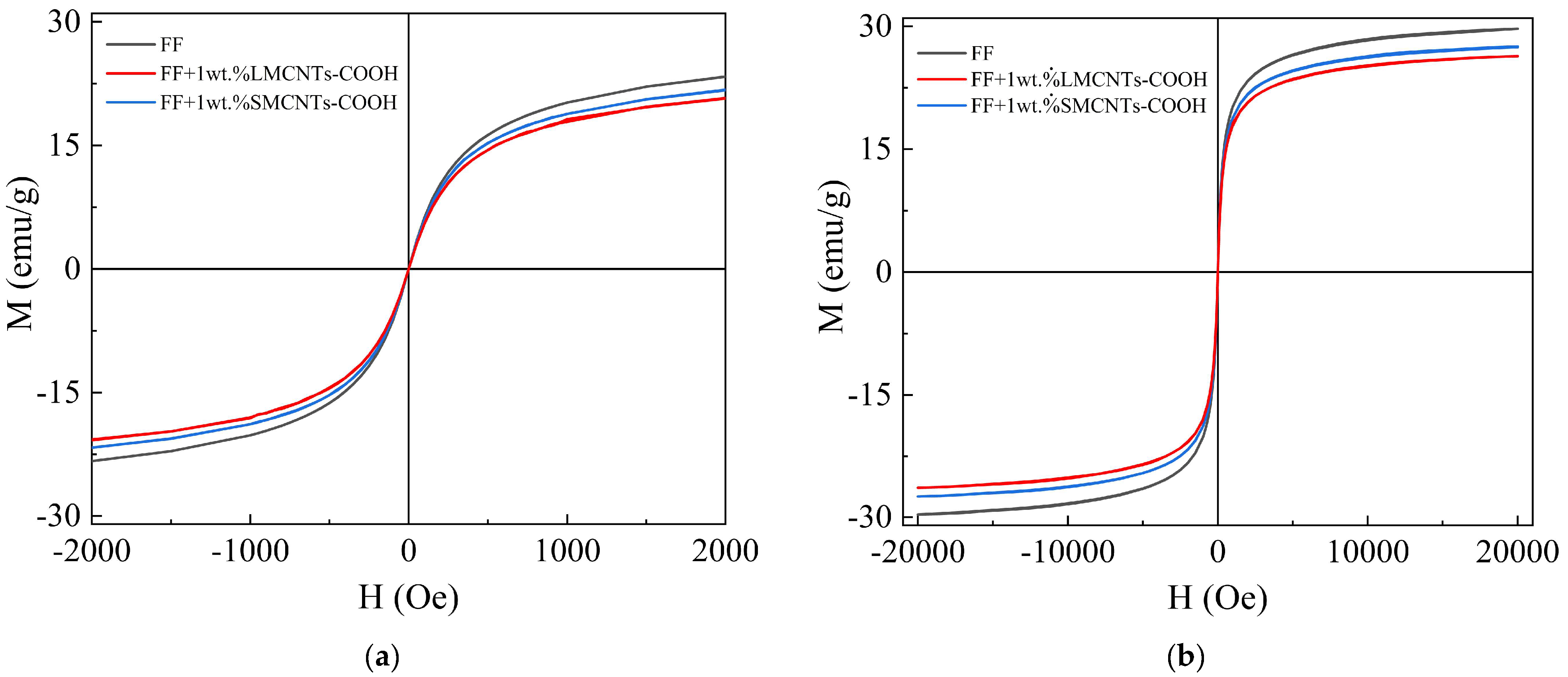
Figure 2 shows the magnetization curves measured at 20 °C for the pure ferrofluid, FF + 1 wt.% LMCNTs-COOH, and FF + 1 wt.% SMCNTs-COOH. Under the pole shoes in a ferrofluid seal, the magnetic field strength can be extremely high, up to 20,000 Oe. Therefore, the magnetization at H = 20,000 Oe is selected to characterize the magnetic behavior of the fluids in this paper.
As seen in Figure 2, within the ±500 Oe range, the magnetization of the magnetic fluid increases rapidly with the applied magnetic field intensity H. Beyond this range, the increase in magnetization slows progressively, and when the H > 10,000 Oe, the magnetization tends to saturate. Moreover, in Figure 2, the magnetization values of the fluids follow the order: FF > FF + 1 wt.% SMCNTs-COOH > FF + 1 wt.% LMCNTs-COOH. This trend can be attributed to two factors. First, the addition of carbon nanotubes reduces the number of magnetic nanoparticles per unit mass in the hybrid fluids relative to the pure ferrofluid. Second, the addition of carbon nanotubes increased the viscosity of the magnetic fluid—often referred to as the “viscous magnetic effect” [22]. The elevated viscosity suppresses the Brownian motion of the magnetic nanoparticles, thereby promoting their aggregation into annular structures. Due to the increased viscosity, the mobility of these nanoparticles is reduced, leading to the stabilization of the closed-flux annular structures even under high magnetic fields. However, these annular structures do not contribute to the overall magnetization under an applied field. Therefore, the magnetization of hybrid magnetic fluids is lower than ferrofluids. Moreover, since LMCNTs induce a larger viscosity increase than SMCNTs, the hybrid magnetic fluid containing LMCNTs exhibits the lowest magnetization.

3. Thermal Conductivity Measurement Apparatus and Methodology

3.1. Thermal Conductivity Measurement System

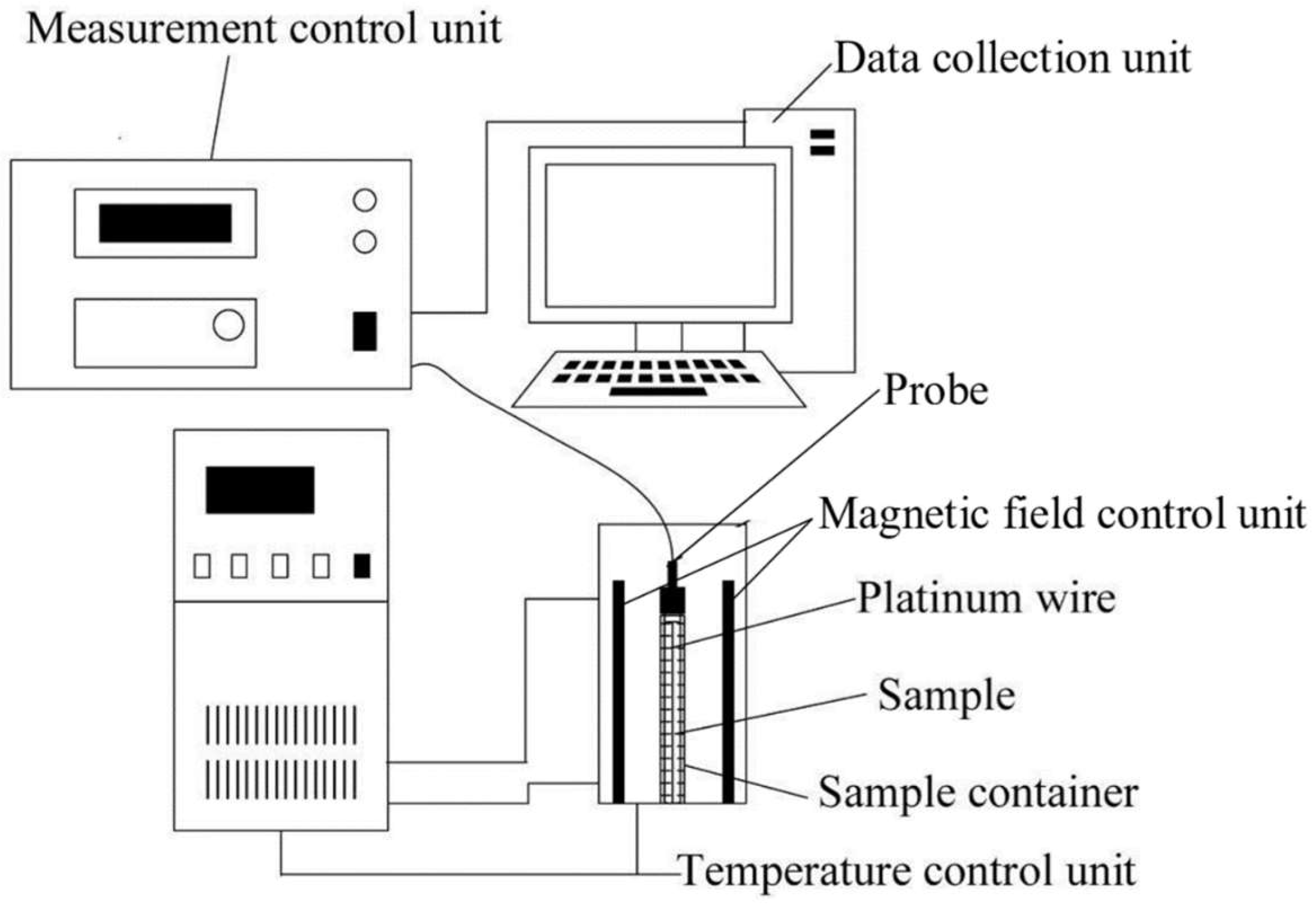
In the magnetic fluid rotary seal, the magnetic fluid is tightly confined around the rotating shaft, thereby inducing significant viscous dissipation during rotation and effectively generating a radial heat source. Therefore, in this paper, we have constructed an experimental system with an external magnetic field, based on the transient hot-wire method, to measure the thermal conductivity of hybrid magnetic fluids. As illustrated in Figure 3, the system comprises the following key parts: a sensing probe, a temperature control unit (TCU), a magnetic field control unit (MFCU), a measurement control unit (MCU), and a data collection unit (DCU). The sensing probe, MCU, and DCU are implemented using a commercial DRE-2A thermal conductivity analyzer (Xiangtan Instrument Co., Ltd., Xiangtan, China). To suppress the thermal convection during measurements, a platinum wire with a length of 130 mm and a diameter of 60 μm is selected as the probe, ensuring it closely approximates an infinite line heat source. The TCU incorporates a low-temperature thermostatic bath, a double-walled water-bath glass test tube, and calibrated thermocouples. In conjunction with the MFCU, it enables constant temperature measurements within the range of 20–80 °C. Both permanent magnets and electromagnets can serve as magnetic field sources. However, adjusting the magnetic field strength with permanent magnets leads to variations in magnetic field uniformity. Adjusting the magnetic field strength of a permanent magnet inherently alters its field uniformity, introducing a magnetic field gradient. The presence of a magnetic field gradient can induce undesirable movement of the magnetic nanoparticles within the fluid, resulting in measurement errors. Therefore, a custom-designed electromagnet is employed as the magnetic field control unit in this study.
Actually, the application of the transient hot-wire method for measuring the thermal conductivity of anisotropic magnetic fluids is subject to certain limitations. As illustrated in Figure 4, the electromagnet generates a uniform magnetic field in the measurement region. The magnetic field is oriented along the x-direction, while the hot wire is positioned along the z-direction. Heat flux transfers radially from the heat source (hot wire), establishing a radial temperature gradient (indicated by black dashed arrows). Under the influence of the magnetic field, the magnetic nanoparticles align parallel to the field lines (x-direction), inducing thermal conductivity anisotropy. Specifically, the thermal conductivity parallel to the magnetic field (k) substantially exceeds the thermal conductivity perpendicular to the field (k). However, due to the orthogonal orientation between the hot wire (z-axis, heat source) and the magnetic field (x-axis), the radial heat flux is not fully parallel to the magnetic field; thus, the measured thermal conductivity (k) represents an effective value incorporating contributions from both k and k. In this paper, a theoretical method will be employed to calculate the k of the magnetic fluid by using the measured thermal conductivity k in Section 4.

3.2. Electromagnetic Design and Simulation

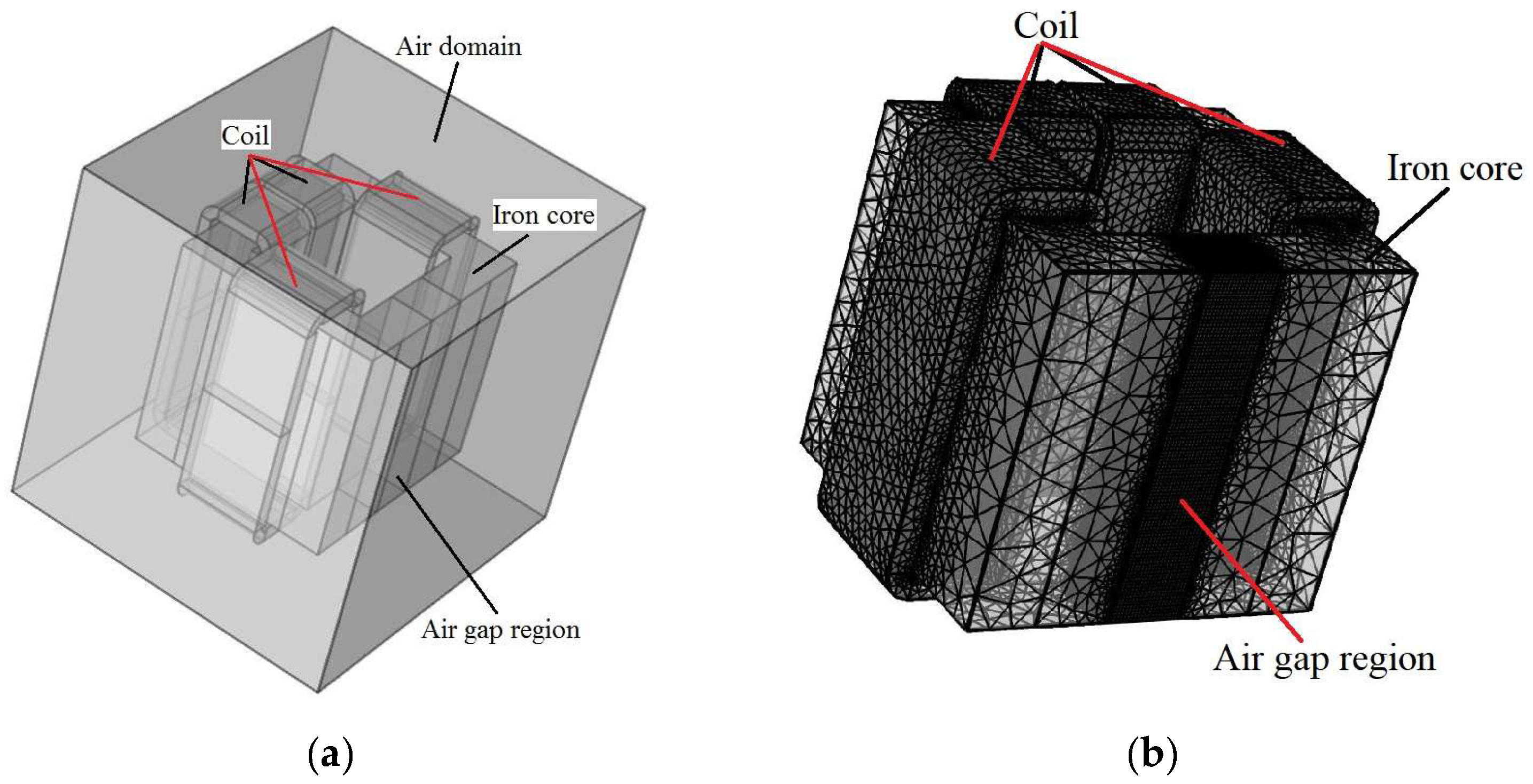
To optimize the electromagnet’s design and elucidate the relationships among the coil parameters, core geometry, and magnetic field uniformity, finite element method (FEM) simulations are conducted using COMSOL Multiphysics 5.3. The geometric model of the electromagnet is presented in Figure 5. The model incorporates an encompassing air domain, with the relative permeability of both the coil and the air domain set to 1. The iron core is modeled using the built-in “soft iron (with losses)” material in the software, with its magnetization performance characterized by a B-H curve. The coil is made of enameled copper wire. The number of turns of the coil indicated by black lines are denoted as N1 and N2, with corresponding currents I1 and I2, where N1 = N2 and I1 = I2. Similarly, for the coil indicated by red lines, the number of turns are N3 and N4, with currents I3 and I4, where N3 = N4 and I3 = I4. In the simulation, the computational mesh employs triangular elements within the air gap region, with a swept mesh distribution to capture the field gradients. And the remaining regions utilize tetrahedral elements.
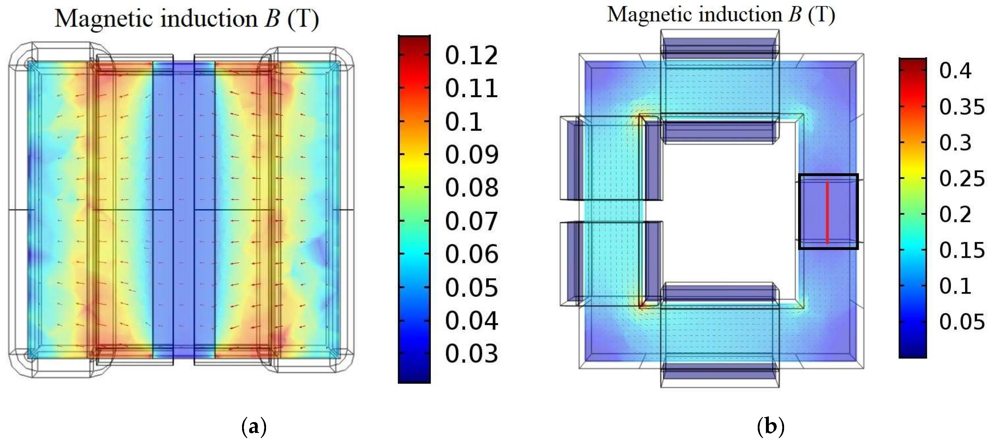
Figure 6 illustrates the vertical (a) and horizontal (b) cross-sectional planes of the electromagnet. Figure 7 presents contour and vector plots of the magnetic induction (B). The length and direction of the arrows represent the strength and direction of the magnetic field, respectively. The plots reveal that the magnetic induction lines near the air gap edges exhibit significant nonuniformity and non-parallelism, indicative of higher field gradients. In contrast, the central region of the air gap displays a more uniform field distribution, with nearly parallel magnetic induction lines.
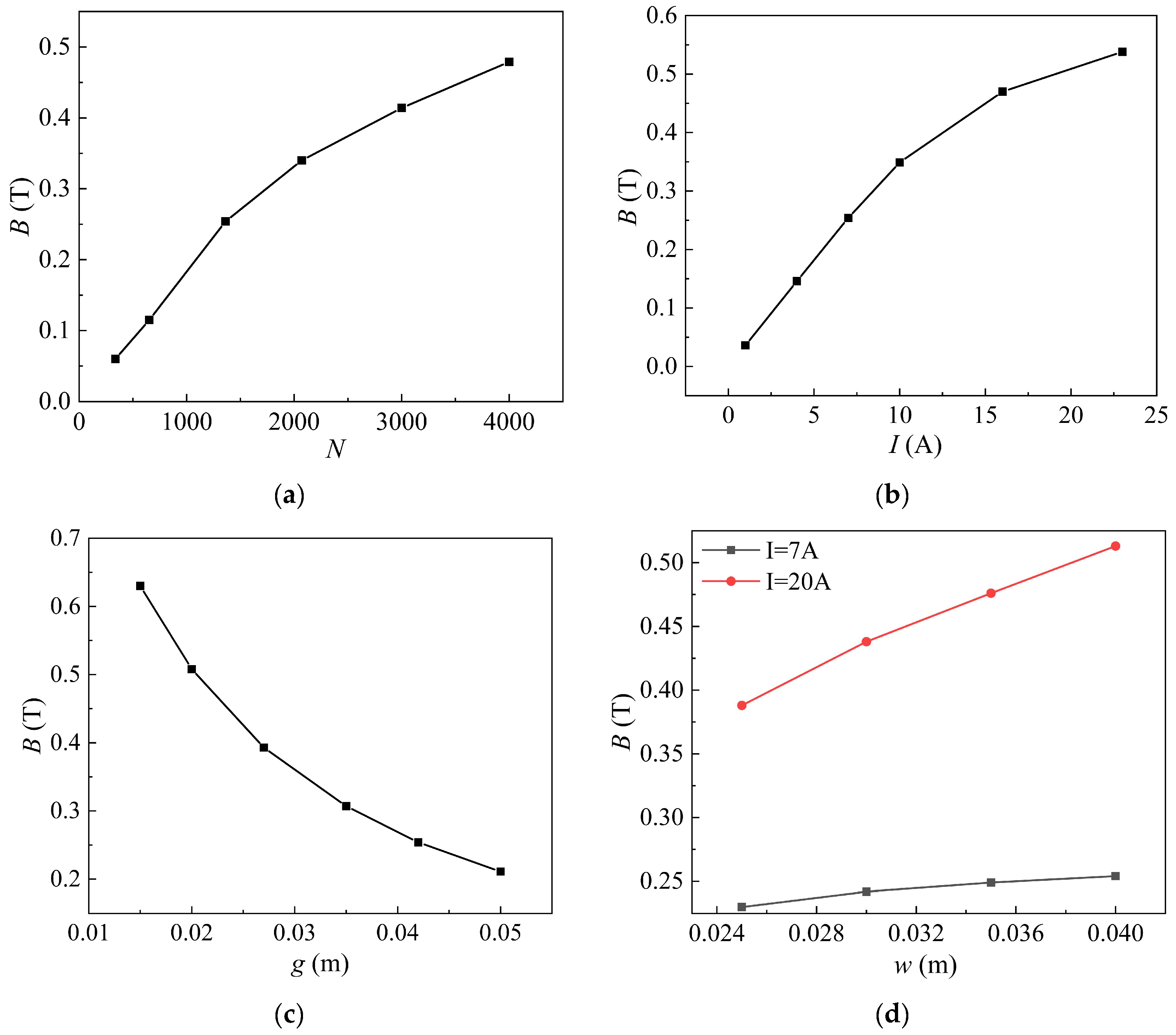
Figure 8 presents parametric studies investigating the influence of coil turns (N), current (I), air gap distance (g), and iron core width (w) on the magnetic induction. Figure 8a demonstrates that, for a fixed current (I = 7 A), the magnetic induction increases linearly with the number of turns at lower values of N. As N increases further, the rate of increase slows down, which is attributed to the gradual magnetic saturation in the iron core. Figure 8b shows a similar trend for the current, with a linear increase in B at lower currents (for N = 1360 turns) followed by a gradual saturation at higher currents. In actual design, although increasing both N and I can enhance the magnetic field strength, limitations and risks rise due to excessive coil heating at their higher values. Therefore, the number of coil turns and the current should not be too large. Figure 8c reveals an inverse relationship between the magnetic induction and the air gap distance, with a rapid decrease in field strength at a smaller g and a more gradual decline at a larger g (for I = 7 A and N = 1360 turns). From Figure 8d, B increases with the increase in width w. This is due to the larger permeable area and reduced magnetic resistance at larger w. To facilitate magnetic field analysis, a magnetic field uniformity parameter Γ is defined (Equation (2)), where Bmax and Bmin represent the maximum and minimum magnetic induction within the volume occupied by the magnetic fluid, respectively. Table 2 summarizes the variation in magnetic field uniformity with current and iron core width. The results indicate that increasing the iron core width improves magnetic field uniformity and increases the magnetic induction, but it also leads to an increase in the mass of the core. Therefore, a judicious selection of iron core width is crucial to balance these competing factors.
Γ = B max B min 1 × 100 % ,
Based on the considerations above, including magnetic field strength, heat dissipation, and weight, the final iron core dimensions of the electromagnet is shown in Figure 9 (a = 11 cm, b = 13 cm, g = 4.2 cm, w = 4 cm, h = 20 cm), with the core material being electrical pure iron. The coil configuration is as follows (refer to Figure 4): symmetrically distributed coils with a wire diameter of 1.4 mm, N1 = N2 = 196 turns (black lines), N3 = N4 = 358 turns (red lines), total turns = 1108. The coils are connected in parallel to facilitate heat dissipation and simplify electrical connections. In the experimental setup, the magnetic fluid is contained within the inner chamber of the double-walled water-bath glass test tube (part of the temperature control unit). The magnetic fluid occupies a cylindrical volume with a diameter of 13 mm and a height of 165 mm. The center of this cylindrical volume coincides with the center of the air gap region (a rectangular prism defined by w, g, and h). The glass test tube is placed on a custom-designed rack, with the outer chamber connected to a circulating constant-temperature water bath. The sensing probe is held by a dedicated fixture and immersed in the magnetic fluid. By precisely controlling the coil current and the bath temperature, the thermal conductivity of the magnetic fluid can be measured under various magnetic field strengths and temperatures, with data acquisition managed by a computer.

3.3. Comparison of Electromagnet Performance: Theoretical, Simulated, and Experimental Result

3.3.1. Theoretical Magnetic Induction

For the electromagnet geometry shown in Figure 5, according to Ampère’s Circuital Law, the magnetic flux (Φ) through the air gap of the electromagnet is given by [23]
Φ R m + R g = N i I i ,
where Rm and Rg are the magnetic reluctances of the iron core and air gap, respectively. The term ΣNiIi represents the total magnetomotive force (MMF), with Ni being the number of turns and Ii being the current for the i-th coil.
In this study, the Rm can be approximated theoretically as Equation (4), where l is the effective magnetic path length within the core, μr is the relative permeability of the core material, μr = 542 [24], μ0 is the permeability of free space, and S is the cross-sectional area of the core.
R m = l μ 0 μ r S = 2 a + b + 2 w g μ 0 μ r w h = 1.097 × 10 5 ,
The air gap reluctance (Rg) is given by Equation (5).
R g = g μ 0 S mod = g μ 0 w + K g h + K g = 3.713 × 10 6 ,
where g is the air gap distance, and Smod is a modified cross-sectional area of the air gap to account for fringing effects. Due to the relatively large air gap, the magnetic induction lines spread out, effectively increasing the area through which the induction line passes. The modification factor is given by K = 0.307/π, and Smod = (w + Kg)(h + Kg). The theoretical average magnetic flux density (BTave) in the air gap can then be estimated as
B Tave = N i I i R m + R g w + K g h + K g ,

3.3.2. Simulated Magnetic Induction

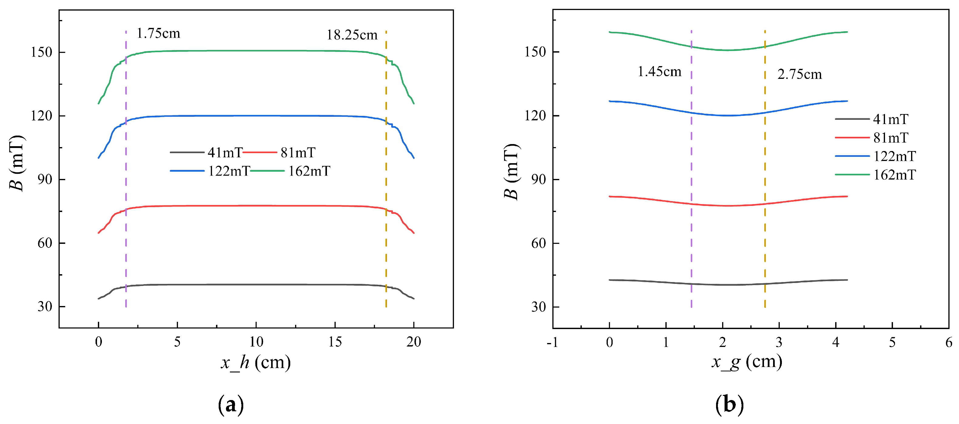
Figure 10 presents the simulated magnetic induction profiles along the vertical (a) and horizontal b centerlines of the electromagnetic air gap. The vertical line corresponds to the red line in Figure 7a, and the horizontal line corresponds to the red line in Figure 7b. The plots demonstrate the symmetry of the magnetic field distribution. In Figure 10a, the region between 1.75 cm and 18.25 cm corresponds to the height of the magnetic fluid sample. In Figure 10b, the region between 1.45 cm and 2.75 cm corresponds to the diameter of the magnetic fluid sample. Good magnetic uniformity within these regions could be found in our simulation.

3.3.3. Comparison

To quantify the agreement between the experimental measurements, simulations, and theoretical calculations, the magnetic induction at the center of the air gap is denoted as BEmid (experimental), BSmid (simulated), and BTave (theoretical). The relative errors between theory and experiment (ξT_E) and between simulation and experiment (ξS_E) are defined as
ξ T _ E = B Tave B Emid B Emid × 100 % ,
ξ S _ E = B Smid B Emid B Emid × 100 % ,
Table 3 presents a comparison of the magnetic induction values. The results demonstrate excellent magnetic field uniformity, with a calculated uniformity parameter (Γ) of 4.53%. Furthermore, the simulated, theoretical, and experimental values of B at the air gap center show good agreement, with a maximum relative error of 6.92% and most errors falling below 5%. The discrepancies can be attributed to several factors, including the estimated value of the relative permeability of the core material in the theoretical calculations, inaccuracies in the fringing field correction factor for the air gap area, and the material property definitions used in the FEM simulations.

3.4. Verification of Magnetic Field Independence of the Measurement System

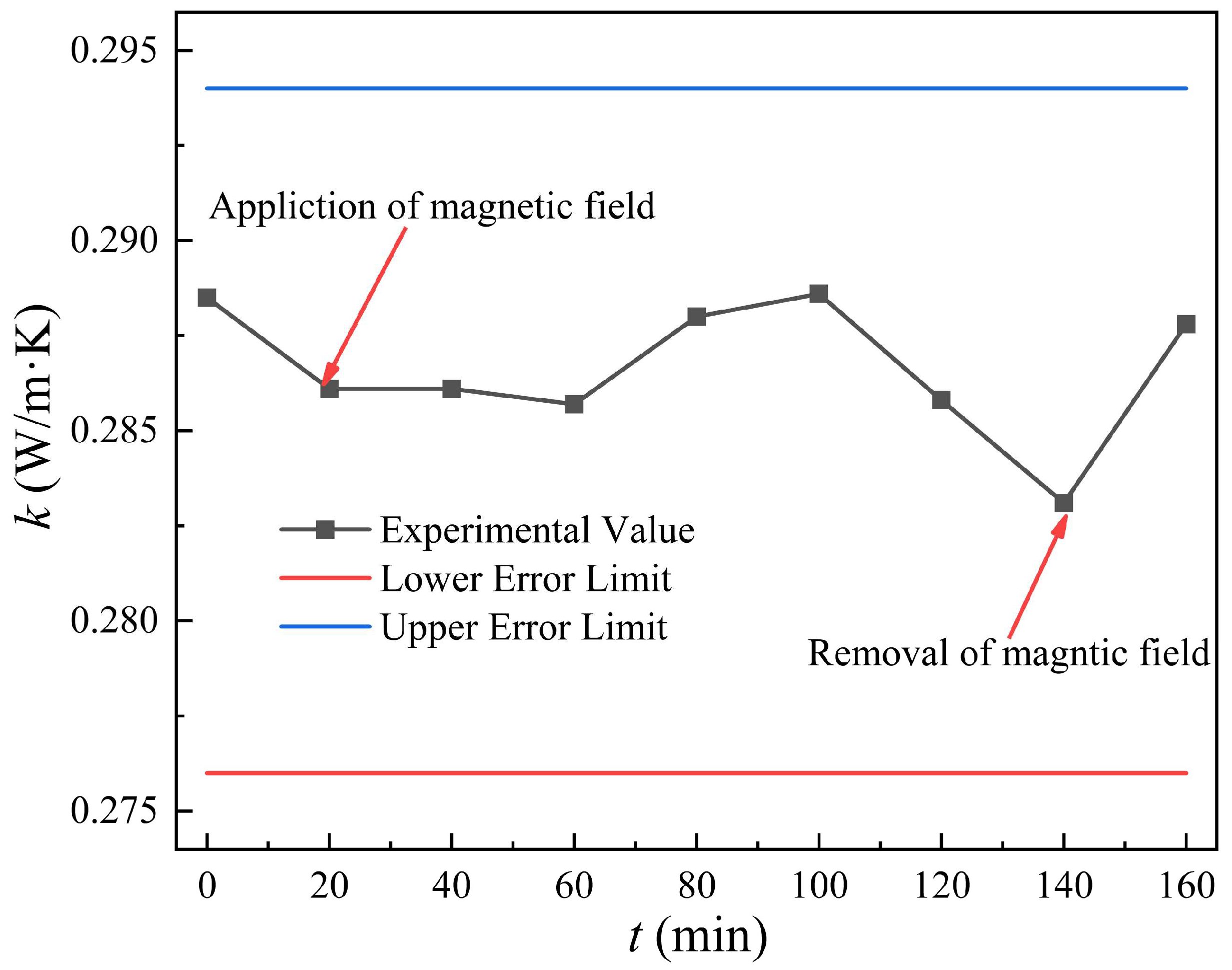
Prior to conducting the main experiments, the measurement system is calibrated using glycerol at room temperature (20 °C) to ensure the reliability of subsequent thermal conductivity measurements. To further validate the accuracy of the measurements in the presence of a magnetic field, the thermal conductivity of glycerol is measured under a constant magnetic field of 41 mT (applies at t = 18 min and removes at t = 140 min after the measurement). The results, as shown in Figure 11, confirm the stability and accuracy of the measurement system. The known thermal conductivity of glycerol at 20 °C is 0.285 W/m∙K [25]. Considering the instrument’s specified accuracy of ±3%, a measurement range of 0.276 to 0.294 W/m∙K is deemed acceptable. The measurements in Figure 11 clearly fall well.

4. Thermal Conductivity Analysis

4.1. Carbon Nanotube Length Effects

Incorporating CNTs into magnetic fluids can significantly enhance their thermal conductivity. In previous studies, the thermal conductivity of hybrid magnetic fluid was typically predicted using the Maxwell model (M) and the Hamilton–Crosser model (HC). The Maxwell model [26], shown in Equation (9), is a classical effective medium theory for dilute suspensions of spherical particles. The Hamilton–Crosser model [27], presented in Equation (10), extends this framework by incorporating an empirical shape factor to account for the non-sphericity of the dispersed phase.
k hf k ff = k MCNT + 2 k ff + 2 ϕ MCNT k MCNT k ff k MCNT + 2 k ff ϕ MCNT k MCNT k ff ,
k hf k ff = k MCNT + n 1 k ff + n 1 ϕ MCNT k MCNT k ff k MCNT + n 1 k ff ϕ MCNT k MCNT k ff ,
where khf and kff denote the thermal conductivities of the hybrid magnetic fluid and the base magnetic fluid, respectively. kMCNT represents the intrinsic thermal conductivity of the MCNTs, kMCNT = 3000 W/m∙K [28]. ϕMCNT is the volume fraction of the MCNTs, related to the weight fraction (wMCNT) through the following equation:
ϕ MCNT = ρ ff ω MCNT ρ ff ω MCNT + ρ MCNT 1 ω MCNT ,
In this study, the densities of the base magnetic fluid (ρff) and the MCNTs (ρMCNT) are 1.35 g/cm3 and 2.1 g/cm3, respectively. The empirical shape factor, n, is defined as 3/ψ, where ψ represents the sphericity of the nanoparticles. Sphericity is defined as the ratio of the surface area of a sphere (with the same volume as the given particle) to the surface area of the given particle. In our calculation, the MCNTs are modeled as cylinders. By using the average length and diameter, the calculated shape factors are nLMCNTs-COOH = 25.21 and nSMCNTs-COOH = 10.06 for the long and short MCNTs, respectively.
As shown in Figure 12, both the Maxwell and Hamilton–Crosser models underestimate the thermal conductivity of the hybrid magnetic fluids compared to the experimental values. It can be attributed primarily to the neglect of interparticle interactions. In the real hybrid magnetic fluids, the MCNTs are not individually dispersed but rather tend to form interconnected agglomerates or networks. Within these agglomerates, direct solid–solid thermal conduction pathways between adjacent MCNTs become significant, thereby enhancing the overall effective thermal conductivity beyond what is predicted by theoretical models (Maxwell model and HC model) that assume isolated particles. Furthermore, the more pronounced deviation between the experimental data and the HC prediction for the SMCNTs-COOH suggests that the formation of agglomerates has a more dominant effect on the overall thermal transport, effectively mitigating the influence of the individual MCNT length. The increased thermal transport through solid–solid contact in the short MCNTs is larger relative to the long MCNTs. The Maxwell model is strictly valid for dilute suspensions of spherical particles, while the HC model, by incorporating the shape factor, provides a more appropriate framework for analyzing the influence of the MCNT length.
The influence of carbon nanotube length on the thermal conductivity of the hybrid magnetic fluid is also presented in Figure 12. To clarify the mechanism of the thermal conductivity enhancement clearly, the relative thermal conductivity is defined in Equation (12), where kFF+MCNTs and kFF are the thermal conductivity for FF + MCNTs nanofluids and ferrofluids, respectively.
Δ k / k = k FF + MCNTs / k FF 1 × 100 % ,
Figure 12a,b show the thermal conductivity and relative thermal conductivity enhancement, respectively, for hybrid magnetic fluids incorporating varying weight fractions of long (LMCNTs-COOH) and short (SMCNTs-COOH) carbon nanotubes. A clear trend is shown: the thermal conductivity of the hybrid magnetic fluid exhibits an approximately linear increase with increasing MCNT weight fraction, irrespective of whether long or short MCNTs are employed. Notably, the incorporation of LMCNTs-COOH results in a more substantial enhancement of the magnetic fluid’s thermal conductivity. Specifically, the addition of 1 wt.% of LMCNTs-COOH and SMCNTs-COOH leads to thermal conductivity increases of 23.39% and 17.69%, respectively, relative to the base magnetic fluid. The major heat transfer mechanisms could be attributed to the MCNTs aggregation and micro-convection caused by Brownian motion of the magnetic particles. As concluded in the previous study [29,30], the aggregation of MCNTs creates paths of lower thermal resistance. With the increase in MCNT weight fractions, there are more MCNTs per unit volume, and it is much easier to form clusters, even networks, of MCNTs. Similarly, longer MCNTs tend to form more effective thermal networks compared to short MCNTs, contributing to the larger enhancement of thermal conductivity. In the present work, the external magnetic field has not been applied. The MCNT aggregation plays a more important role than the micro-convection of magnetic particles.

4.2. Magnetic Field Effects

Figure 13 presents the thermal conductivity of the pure FF, FF + 1 wt.% LMCNTs-COOH, and FF + 1 wt.% SMCNTs-COOH, varying with the magnetic induction in the air gap. The thermal conductivity of the pure ferrofluid increases with an external magnetic field. This phenomenon is attributed to enhanced magnetization, which facilitates the formation of chain-like particle structures aligned with the magnetic field direction, thereby increasing the ferrofluid’s thermal conductivity. However, the overall enhancement in the thermal conductivity of ferrofluid is relatively gentle. The maximum relative thermal conductivity enhancement is only 5.18 (in Table 4). It resulted in the inherent characteristics of the transient hot-wire method, which has certain limitations in the measuring of anisotropic fluids.
As mentioned in Section 3, the measured thermal conductivity (k) represents an effective value incorporating contributions from both k and k. Their relationship has been simplified as Equations (13)–(15) [31,32]:
k = k k ,
k = 1 φ k b + φ k p ,
k = k p k b 1 φ k p + φ k b
where kb is the thermal conductivity of the base fluid (kerosene), kp is the thermal conductivity of the magnetic nanoparticles, and φ is the field-dependent volume fraction of effectively magnetized nanoparticles. By analyzing the measured k within such a theoretical framework, the parallel thermal conductivity k and its relative thermal conductivity Δk/k(%) can be estimated. As detailed in Table 4, k attained its maximum estimated value at a magnetic induction (B) of 122 mT within the air gap, corresponding to a relative parallel thermal conductivity enhancement of 26.21.
Furthermore, Figure 13 also indicates that the thermal conductivity of the ferrofluid decreases at B = 162 mT. This reduction is ascribed to a structural transition from nanoparticle chains to larger columnar structures, contributing to the magnetic particles’ aggregation at high field strengths. In the present study, the magnetic particles ≥15 nm in diameter account for 7.79% of the population. At B = 162 mT, these larger particles likely serve as nucleation sites, promoting the formation of microscale aggregate. This process diminishes the homogeneity of the nanoparticle dispersion and disrupts efficient heat transport pathways, thereby impeding thermal conductivity enhancement [33].
In Figure 13, the magnetic field exerts a less pronounced influence on the thermal conductivity of the hybrid magnetic fluids (containing MCNTs). To further clarify the underlying mechanisms governing the magnetic field response in these hybrid systems, the thermal conductivity under sustained field application is investigated.
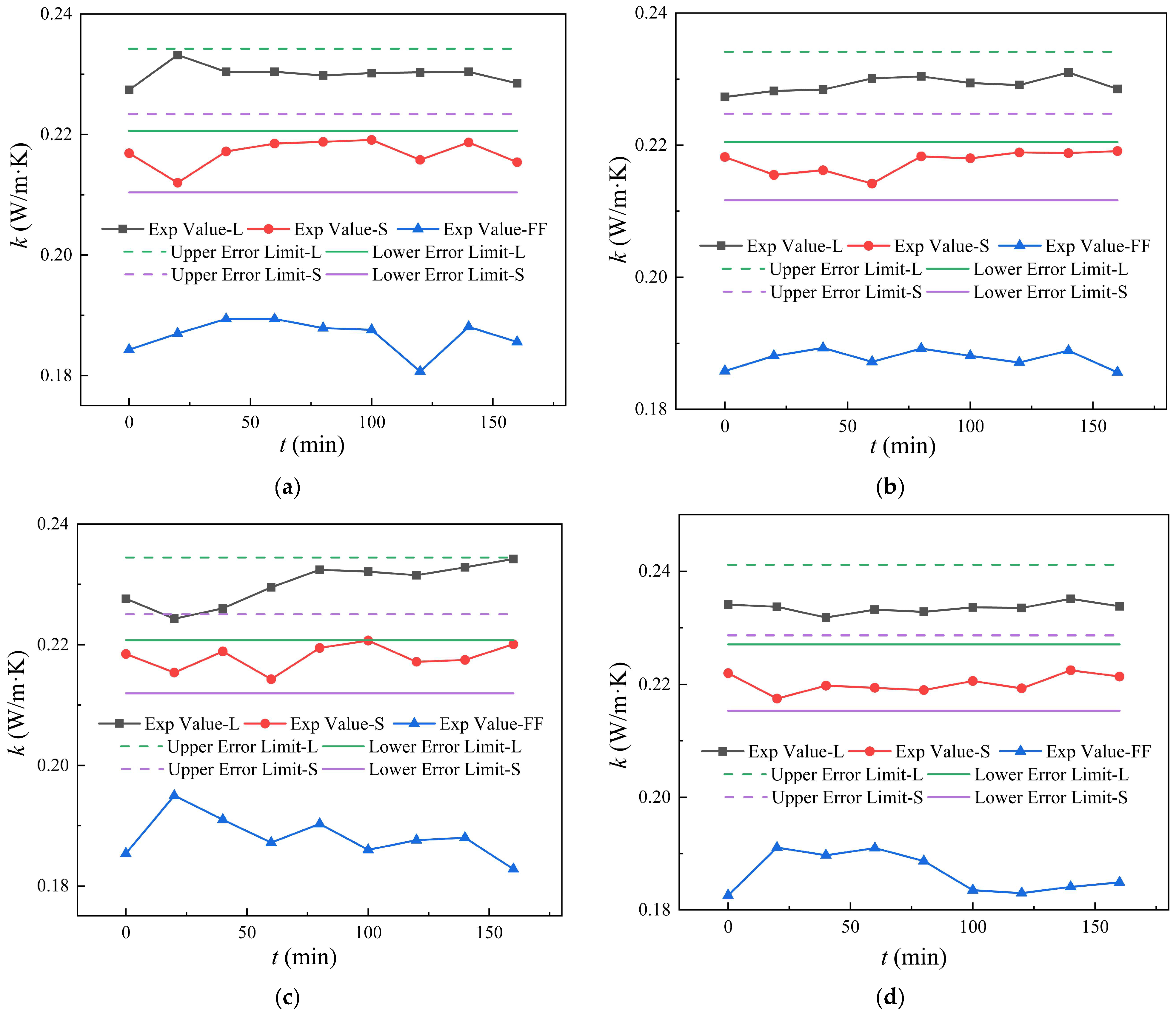
Figure 14 shows the thermal conductivity of the hybrid magnetic fluids and the base magnetic fluid under varying magnetic field strengths (41, 81, 122, and 162 mT). The magnetic field is applied at t = 18 min and removed at t = 140 min. The experimentally measured thermal conductivities are denoted as “Exp Value-L”, “Exp Value-S”, and “Exp Value-FF” for the hybrid magnetic fluid containing LMCNTs-COOH, the hybrid magnetic fluid containing SMCNTs-COOH, and the base magnetic fluid, respectively. Error bounds, representing ±3% of the initial thermal conductivity (t = 0 min) of each fluid, are indicated by “Upper Error Limit-L/S” and “Lower Error Limit-L/S”. In Figure 14, for the pure ferrofluid, the initial application of a magnetic field induces an increase in thermal conductivity across various magnetic fields, a phenomenon that is consistent with the observations illustrated in Figure 13. However, with prolonged exposure to the magnetic field, the thermal conductivity of ferrofluid declines, a reduction that becomes particularly pronounced under strong external magnetic fields. This behavior is also attributed to the structural transition from chain-like formations to columnar assemblies, promoting particle aggregation under a sustained magnetic field. Crucially, for the hybrid magnetic fluids incorporating either type of MCNTs, the thermal conductivity exhibits negligible variation with both magnetic field strength and the magnetic field application time. The observed fluctuations remain within the experimental error bounds. This behavior is similar to some previous studies, which have reported more complex responses of magnetic fluid thermal conductivity to applied magnetic fields, including initial increases followed by decreases, potentially even falling below the zero-field value [12]. The observed stability in the present study can be rationalized by considering the microstructure of the hybrid magnetic fluid. Figure 15 presents micrographs of the FF + 1 wt.% LMCNTs-COOH hybrid magnetic fluid both with and without an applied magnetic field (41 mT). No significant structural rearrangement is evident upon application of the magnetic field. This is likely attributed to the relatively high MCNT loading (1 wt.%), which promotes the formation of a percolating network structure. This interconnected network hinders the large-scale movement of the MCNTs and magnetic nanoparticles in response to the magnetic field, thus preventing substantial changes in the microstructure and, consequently, the macroscopic thermal conductivity. This insensitivity to the magnetic field is a desirable characteristic for their applications, such as magnetic fluid seals, where stable thermal performance under an external magnetic field is essential.

5. Conclusions

This study investigates the thermal conductivity of hybrid magnetic fluids incorporating MCNTs-COOH of varying lengths, both in the presence and absence of an external magnetic field, with the aim of enhancing the thermal properties of the base magnetic fluid. The key findings are summarized as follows: (1) The designed electromagnet produces a magnetic field within the air gap, exhibiting excellent uniformity. Furthermore, a strong agreement is observed between the theoretically calculated, numerically simulated, and experimentally measured magnetic induction. (2) The incorporation of long MCNTs-COOH demonstrates a more substantial enhancement in the thermal conductivity of the magnetic fluid compared to their short counterparts. (3) In the absence of an applied magnetic field, the addition of 1 wt.% long and short MCNTs-COOH results in thermal conductivity improvements of 23.39% and 17.69%, respectively, relative to the ferrofluid. (4) The parallel thermal conductivity of ferrofluid displayed a large improvement of 26.21% when the applied magnetic field was 122 mT. (5) The thermal conductivity of hybrid magnetic fluids containing 1 wt.% MCNTs-COOH exhibited negligible variation with both magnetic field application time (up to 122 min) and magnetic field strength (ranging from 0 to 162 mT). This observed stability in thermal performance suggests that the network structure formed by the MCNTs at this concentration effectively mitigates magnetically induced structural rearrangements that could otherwise alter the thermal transport properties. It indicates the potential suitability of these hybrid magnetic fluids in high-speed magnetic fluid seals, where consistent and efficient heat dissipation is paramount.

Author Contributions

Conceptualization, L.J.; methodology, L.J.; software, L.J.; validation, L.J.; formal analysis, Q.L.; investigation, J.Y. and X.T.; resources, L.J.; data curation, L.J.; writing—original draft preparation, L.J.; writing—review and editing, L.J.; visualization, L.J.; supervision, D.L.; project administration, D.L.; funding acquisition, D.L. All authors have read and agreed to the published version of the manuscript.

Funding

This research received no external funding.

Data Availability Statement

The data presented in this study are available on request from the corresponding author.

Conflicts of Interest

The authors declare no conflict of interest.

References

  1. Decai, L.I. Theory and Application of Magnetic Fluid; Science Press: Beijing, China, 2003. (In Chinese) [Google Scholar]
  2. Decai, L.I. Theory and Application of Magnetic Fluid Sealing; Science Press: Beijing, China, 2010. (In Chinese) [Google Scholar]
  3. Li, Q.; Xuan, Y.; Wang, J. Experimental investigation on transport properties of magnetic fluids. Therm. Fluid Sci. 2005, 30, 109–116. [Google Scholar]
  4. Fang, X.; Xuan, Y.; Li, Q. Anisotropic thermal conductivity of magnetic fluids. Prog. Nat. Sci. 2009, 19, 205–211. [Google Scholar]
  5. Gavili, A.; Zabihi, F.; Isfahani, T.D.; Sabbaghzadeh, J. The thermal conductivity of water base ferrofluids under magnetic field. Exp. Therm. Fluid Sci. 2012, 41, 94–98. [Google Scholar]
  6. Bunoiu, O.M.; Matu, G.; Marin, C.N.; Malaescu, I. Investigation of some thermal parameters of ferrofluids in the presence of a static magnetic field. J. Magn. Magn. Mater. 2020, 498, 166132. [Google Scholar]
  7. Vinod, S.; Philip, J. Impact of field ramp rate on magnetic field assisted thermal transport in ferrofluids. J. Mol. Liq. 2020, 298, 112047. [Google Scholar]
  8. Hong, H.; Wright, B.; Wensel, J.; Jin, S.; Ye, X.R.; Roy, W. Enhanced thermal conductivity by the magnetic field in heat transfer nanofluids containing carbon nanotube. Synth. Met. 2007, 157, 437–440. [Google Scholar]
  9. Theres Baby, T.; Sundara, R. Surfactant free magnetic nanofluids based on core-shell type nanoparticle decorated multiwalled carbon nanotubes. J. Appl. Phys. 2011, 110, 064325. [Google Scholar]
  10. Shahsavar, A.; Salimpour, M.R.; Saghafian, M.; Shafii, M.B. An experimental study on the effect of ultrasonication on thermal conductivity of ferrofluids loaded with carbon nanotubes. Thermochim. Acta 2015, 617, 102–110. [Google Scholar]
  11. Shahsavar, A.; Saghafian, M.; Salimpour, M.R.; Shafii, M.B. Effect of temperature and concentration on thermal conductivity and viscosity of ferrofluids loaded with carbon nanotubes. Heat. Mass. Transf. 2016, 52, 2293–2301. [Google Scholar]
  12. Yavari, M.; Mansourpour, Z.; Shariaty-Niassar, M. Controlled assembly and alignment of CNTs in ferrofluid, Application in tunable heat transfer. J. Magn. Magn. Mater. 2019, 479, 170–178. [Google Scholar]
  13. Liu, W.I.; Alsarraf, J.; Shahsavar, A.; Rostamzadeh, M.; Afrand, M.; Nguyen, T.K. Impact of oscillating magnetic field on the thermal-conductivity of water-Fe3O4 and water-Fe3O4/CNT ferro-fluids: Experimantal study. J. Magn. Magn. Mater. 2020, 479, 258–265. [Google Scholar] [CrossRef]
  14. Xing, M.; Jing, D.; Chen, H.; Zhang, H.; Wang, R. Ice thermal energy storage enhancement using aligned carbon nanotubes under external magnetic field. J. Energy Storage 2022, 56, 105931. [Google Scholar] [CrossRef]
  15. Afrand, M.; Toghraie, D.; Ruhani, B. Effect of magnetic field on thermal conductivity of water-based Fe3O4/CNT hybrid nanofluids. Phys. A Stat. Mech. Its Appl. 2023, 619, 128739. [Google Scholar]
  16. Su, Z.; Cheng, Y.; Liu, Z.; Zhou, J.; Li, D.; Li, Y. Experimental study on thermal conductivity of water-based magnetic fluid loaded with different nanoparticles. Nanomaterials 2023, 13, 2952. [Google Scholar] [CrossRef]
  17. Sidik NA, C.; Adamu, I.M.; Jamil, M.M.; Kefayati GH, R.; Mamat, R.; Najafi, G. Recent progress on hybrid nanofluids in heat transfer applications: A comprehensive review. Int. Commun. Heat. Mass. Transf. 2016, 78, 68–79. [Google Scholar] [CrossRef]
  18. Atashafrooz, M.; Sajjadi, H.; Delouei, A.A. Simulation of combined convective-radiative heat transfer of hybrid nanofluid flow inside an open trapezoidal enclosure considering the magnetic force impacts. J. Magn. Magn. Mater. 2023, 567, 170354. [Google Scholar] [CrossRef]
  19. Rashed, A.S.; Mahmoud, T.A.; Mabrouk, S.M. Enhanced flow and temperature profiles in ternary hybrid nanofluid with gyrotactic microorganisms: A study on magnetic field, Brownian motion, and thermophoresis phenomena. J. Appl. Comput. Mech. 2024, 10, 597–609. [Google Scholar]
  20. Li, Q.; Zhao, J.; Jin, L.; Li, D. Experimental study on thermal conductivity and magnetization behaviors of Kerosene-based ferrofluid loaded with multiwalled carbon nanotubes. ACS Omega 2020, 5, 13052–13063. [Google Scholar] [CrossRef]
  21. Allen, T. Particle Size Measurement; Chapman and Hall: London, UK, 1981. [Google Scholar]
  22. Li, J.; Gong, X.M.; Lin, Y.Q.; Liu, X.D.; Chen, L.L.; Li, J.M.; Mao, H.; Li, D.C. Investigation into loss in ferrofluid magnetization. Aip Adv. 2014, 4, 077123. [Google Scholar] [CrossRef]
  23. Zhang, G.S.; Lu, J. Electromagnet and Automatic Electromagnetic Components; China Machine Press: Beijing, China, 1982. (In Chinese) [Google Scholar]
  24. NDT personnel technical qualification examination committee of ordnance industry. In Handbook of Magnetic Characteristic Curves of Common Steel; China Machine Press: Beijing, China, 2003. (In Chinese)
  25. Jiarong, Z.; Tingyuan, Z. Handbook of Thermophysical Properties of Materials Commonly Used in Engineering; New Times Press: Beijing, China, 1987. (In Chinese) [Google Scholar]
  26. Qiu, L.; Zhu, N.; Feng, Y.; Michaelides, E.E.; Żyła, G.; Jing, D.; Zhang, X.; Norris, P.M.; Markides, C.N.; Mahian, O. A review of recent advances in thermophysical properties at the nanoscale: From solid state to colloids. Phys. Rep.-Rev. Sect. Phys. Lett. 2020, 843, 1–81. [Google Scholar] [CrossRef]
  27. Hamilton, R.L.; Crosser, O.K. Thermal conductivity of heterogeneous two-component systems. J. Ind. Eng. Chem. Fundam. 1962, 1, 27–40. [Google Scholar]
  28. Walvekar, R.; Faris, I.A.; Khalid, M. Thermal conductivity of carbon nanotube nanofluid—Experimental and theoretical study. Heat. Transf.—Asian Res. 2012, 41, 145–163. [Google Scholar] [CrossRef]
  29. Kúdelčík, J.; Hardoň, Š.; Bury, P.; Timko, M.; Kopčanský, P.; Mitróová, Z. Acoustic spectroscopy of sunctionalized carbon nanotubes in magnetic fluid. J. Magn. Magn. Mater. 2020, 502, 166538. [Google Scholar] [CrossRef]
  30. Hardoň, Š.; Kúdelčík, J.; Jahoda, E.; Kúdelčíková, M. The magneto-dielectric anisotropy effect in the oil-based ferrofluid. Int. J. Thermophys. 2019, 40, 24. [Google Scholar] [CrossRef]
  31. Takegoshi, E.; Imura, S.; Hirasawa, Y.; Takenaka, T. A Method of measuring the thermal conductivity of solid materials by transient hot wire method of comparison. Bull. JSME 1982, 25, 395–402. [Google Scholar] [CrossRef]
  32. Carson, J.K.; Lovatt, S.J.; Tanner, D.J.; Cleland, A.C. Thermal conductivity bounds for isotropic, porous materials. Int. J. Heat. Mass. Tran. 2005, 48, 2150–2158. [Google Scholar] [CrossRef]
  33. Vinod, S.; Philip, J. Role of field-induced nanostructures, zippering and size polydispersity on effective thermal transport in magnetic fluids without significant viscosity enhancement. J. Magn. Magn. Mater. 2017, 444, 29–42. [Google Scholar] [CrossRef]
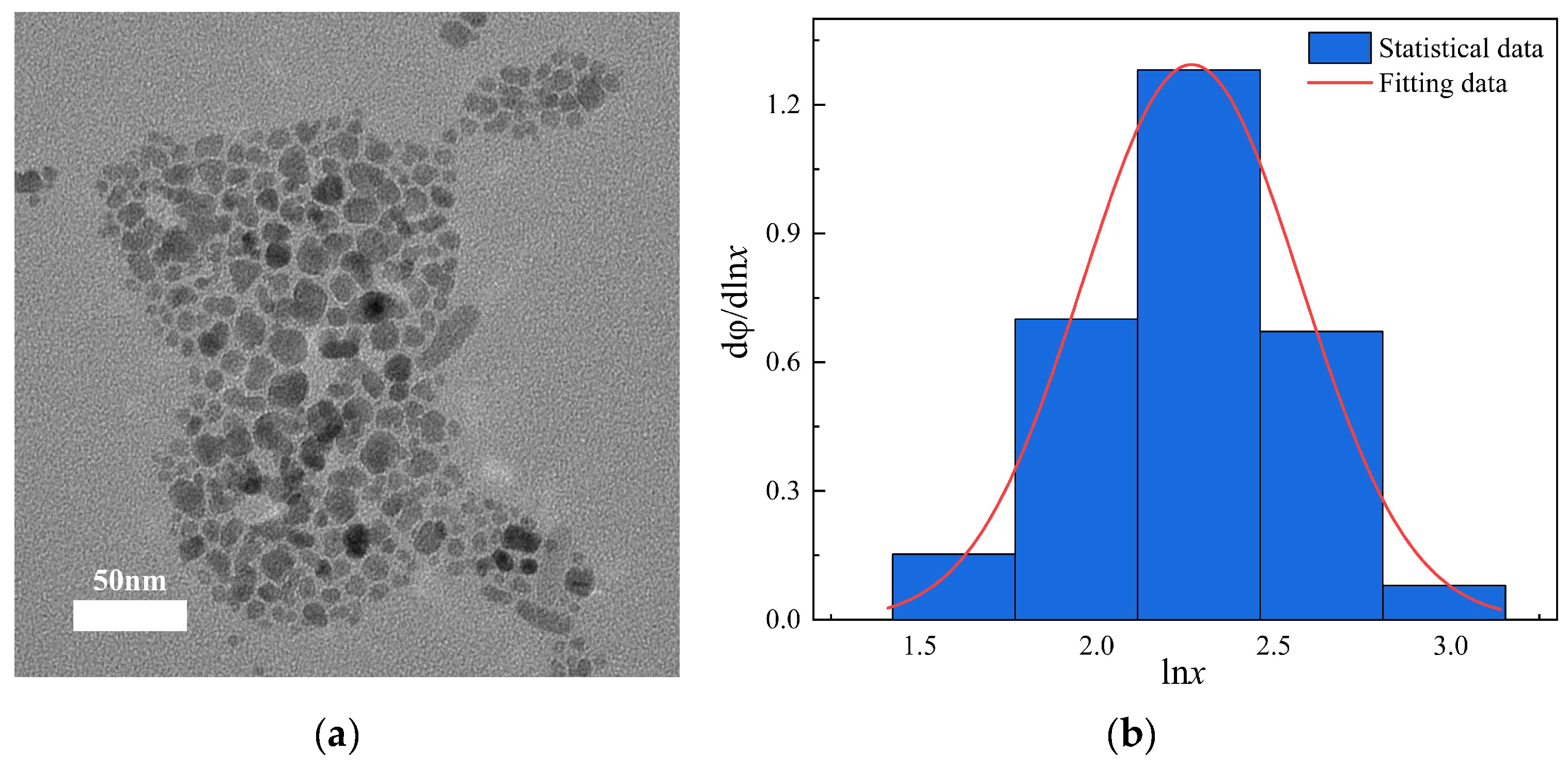
Figure 1. Different characterizations of ferrofluid: (a) A TEM image of ferrofluid; (b) statistical graph of magnetic particle size.
Magnetochemistry 11 00030 g001
Figure 2. Magnetization curves at 20 °C within (a) a small magnetic field range ± 2000 Oe, (b) a large magnetic field range ± 20,000 Oe.
Magnetochemistry 11 00030 g002
Figure 3. Experimental apparatus for thermal conductivity measurement.
Magnetochemistry 11 00030 g003
Figure 4. Schematic diagram of the relative positions of the magnetic field and hot wire.
Magnetochemistry 11 00030 g004
Figure 5. (a) Structure diagram of electromagnet simulation, (b) mesh distribution in different regions.
Magnetochemistry 11 00030 g005
Figure 6. Location diagram of (a) vertical section and (b) horizontal section.
Magnetochemistry 11 00030 g006
Figure 7. Magnetic induction of (a) vertical section; (b) horizontal section.
Magnetochemistry 11 00030 g007
Figure 8. The influence of (a) coil turns, (b) current, (c) air gap distance, and (d) iron core width on the magnetic induction.
Magnetochemistry 11 00030 g008
Figure 9. Diagram of actual size of electromagnet: (a) isometric view; (b) top view; (c) right view.
Magnetochemistry 11 00030 g009
Figure 10. The simulated magnetic induction (a) along the vertical centerlines of the air gap; (b) along the horizontal centerlines of the air gap.
Magnetochemistry 11 00030 g010
Figure 11. Measurement of thermal conductivity of glycerin.
Magnetochemistry 11 00030 g011
Figure 12. Effect of carbon nanotube length on (a) thermal conductivity and (b) comparative thermal conductivity of magnetic fluids.
Magnetochemistry 11 00030 g012
Figure 13. Thermal conductivity of magnetic fluids at different magnetic induction in the air gap.
Magnetochemistry 11 00030 g013
Figure 14. Variation in thermal conductivity of FF + 1 wt.% MCNTs-COOH hybrid magnetic fluid with effect time of magnetic field under different magnetic fields: (a) 41 mT, (b) 81 mT, (c) 122 mT, and (d) 162 mT.
Magnetochemistry 11 00030 g014
Figure 15. Microscopic images of hybrid magnetic fluid (a) in the absence of magnetic field; (b) in the presence of magnetic field.
Magnetochemistry 11 00030 g015
Table 1. Details of samples.
Name of the SamplesWeight Fraction of MCNTs-COOH (%)
FF + 0.1 wt.% LMCNTs-COOH0.1
FF + 0.5 wt.% LMCNTs-COOH0.5
FF + 1 wt.% LMCNTs-COOH1
FF + 0.1 wt.% SMCNTs-COOH0.1
FF + 0.5 wt.% SMCNTs-COOH0.5
FF + 1 wt.% SMCNTs-COOH1
Table 2. The magnetic field uniformity changes with current and iron core width.
W (m)0.030.0350.04
Γ at I = 7 A9.6%7.1%4.6%
Γ at I = 20 A9.9%7.4%4.9%
Table 3. The comparison of magnetic induction.
I1 (A)I2 (A)BEmid (mT)BTave (mT)BSmid (mT)ξT_E (%)ξS_E (%)Γ (%)
1.850.994141.6740.451.64−1.354.53
3.551.908179.9977.62−1.25−4.174.53
5.492.94122123.61120.071.32−1.584.53
6.903.69162155.39150.79−4.08−6.924.53
Table 4. The relative thermal conductivity (Δk/k(%)) and relative parallel thermal conductivity (Δk/k(%)) at different B.
BEmid (mT)41 (mT)81 (mT)122 (mT)162 (mT)
Δk/k(%)1.463.095.813.69
Δk/k(%)17.9621.0526.2122.19
Disclaimer/Publisher’s Note: The statements, opinions and data contained in all publications are solely those of the individual author(s) and contributor(s) and not of MDPI and/or the editor(s). MDPI and/or the editor(s) disclaim responsibility for any injury to people or property resulting from any ideas, methods, instructions or products referred to in the content.