Article

The Influence of Current Magnitudes and Profiles on the Sedimentation of Magnetorheological Fluids: An Experimental Work

1
Department of Mechanical Engineering, Kongju National University, Cheonan 31080, Republic of Korea
2
Department of Future Convergence Engineering, Kongju National University, Cheonan 31080, Republic of Korea
3
Department of Mechanical Design Engineering, Kumoh National Institute of Technology, Gumi 39177, Republic of Korea
4
Department of Mechanical Engineering, The State University of New York Korea (SUNY Korea), Incheon 21985, Republic of Korea
5
Department of Mechanical Engineering, Industrial University of Ho Chi Minh City, Ho Chi Minh City 70000, Vietnam
*
Authors to whom correspondence should be addressed.
Magnetochemistry 2024, 10(3), 18; https://doi.org/10.3390/magnetochemistry10030018
Submission received: 22 January 2024 / Revised: 5 March 2024 / Accepted: 5 March 2024 / Published: 7 March 2024

Abstract

:
Magnetorheological fluids (MRFs) are widely used for various kinds of controllable devices since their properties can be controlled by an external magnetic field. Despite many benefits of MRFs, such as fast response time, the sedimentation arisen due to the density mismatch of the compositions between iron particles and carrier oil is still one of bottlenecks to be resolved. Many studies on the sedimentation problem of MR fluids have been carried out considering appropriate additives, nanoparticles, and several carrier oils with different densities. However, a study on the effect of current magnitudes and profiles on the sedimentation is considerably rare. Therefore, this study experimentally investigates sedimentation behaviors due to different current magnitudes and different magnitude profiles such as square and sine waves in different diameters. The evaluation was performed by visual observation to obtain the sedimentation rate. It was found that the average sedimentation rate of the square type of current is slower compared to the sinusoidal type. It has also been identified that the higher intensity of the applied current results in a stronger electromagnetic field, which could slow down the sedimentation. The results achieved in this work can be effectively used to reduce particle sedimentation in the controller design of various application systems utilizing MRFs in which the controller generates a different magnitude and different profile of the external magnetic field.

1. Introduction

Materials that can be controlled by external stimuli to cause dramatic changes in their properties are referred to as smart materials. Among the smart materials that can be affected by the magnetic field are magnetorheological (MR) fluids. MR fluids behave like Newtonian fluids under normal conditions, meaning that their magnetic particles can move freely in the absence of a magnetic field. However, when the magnetic field is applied, the structure of the fluids transforms into a solid-like structure and the particles will form chain structures, which are known as Bingham plastic materials [1]. The iron particles evenly disperse to the carrier fluids in milliseconds after the magnetic field is removed, making it possible to control the MR effect almost in real-time conditions. Because of these characteristics, MR fluids are widely used in various device applications, including MR clutches [2], MR brakes [3], MR dampers [4], and MR mounts [5]. Another technology for material removal [6,7] and medical devices has also been proposed [8]. Furthermore, MR fluids have been utilized extensively in surface precision machining in recent years. Even though surface precision machining using MR fluid technology has a better machining result than traditional machining, sedimentation may affect the machining precision. Specifically, the machining accuracy is highly dependent on the size, shape, channel length, and current input [9,10,11,12]. This may impact the magnetorheological properties related to surface area elimination. The general process and the scheme of surface precision machining are portrayed in Figure 1. The process of the polishing medium will be circulated, cycling in and out through the MR fluid storage and abrasive slurry. Then, abrasives and carbonyl iron particles are spread throughout the carrier fluids to form the polishing medium.
Generally, MR fluids contain carbonyl iron particles and carrier fluids, which have a density of around 7.5 g/cm3 and 1 g/cm3, respectively [13]. This significant difference in density may cause the relative motion in the settlement of the carbonyl iron particles on the bottom under the influence of gravity over time, which is called sedimentation. Sedimentation of MR fluids itself has an impact on the fluids’ performance and longevity, and frequent disposal of the fluids may lead to a severe environmental impact [14]. Since sedimentation is considered a serious problem for commercial applications, many researchers have developed many methods to prevent sedimentation. The capability of MR fluids to stand against the settling particle is usually called sedimentation stability. Various developments for the improvement of sedimentation stability have been conducted, including modifying the particles, modifying the carrier fluids, adding additives, and combining the mentioned methods [15]. A previous study by K. Shah et al. [16] modified the particles to plate-like iron particles, which proved that it could reduce sedimentation by testing the modified MR fluids to the small-sized damper. Another development by modifying carrier fluids was carried out by S. Zhibin et al. [17]. By using molybdenum disulfide as the lubricant, the result showed the improvement of the anti-sedimentation in the MR fluids because it generated a good wetting effect, high zero-field viscosity, and a small contact angle. In addition, H. Cheng et al. [18] experimented by adding additives by coating the surface of iron particles with organic molecules, which resulted in an increment in suspension stability and a reduction in the sedimentation rate without significantly reducing the MR effect. Furthermore, the study of combining the modified magnetic particles, carrier fluids, and additives was performed, and resulted in good stability against sedimentation [19,20,21]. As mentioned before, recent studies of surface precision machining using MR fluids also consider sedimentation as a crucial problem that needs to be prevented since it influences machining accuracy. The effort for this was only by coating the iron particles using silica, which was proposed by K.P. Hong et al. [22]. However, these methods are not applicable and useable yet for practical applications such as MR dampers since they need a certain response time and MR performance [15]. Therefore, another method to improve the sedimentation stability in an applicable way for the commercialized MR fluids needs to be proposed to develop MR fluid application.
It was found that recent studies only conducted experiments based on a constant magnetic field influence, which is associated with the measurement methods of sedimentation. A study by K.P. Lijesh et al. [23] used a 1 T Neodymium magnet (constant magnetic field) to generate a uniform magnetic field to measure the settling particles by utilizing the hall sensors. The testing parameters for the study were MR fluids with three different surfactants (tetramethylammonium hydroxide, citric acid, and oleic acid) without any magnetism influence. By comparing the voltage value of the sedimentation profile that was measured using data acquisition systems through the hall sensors, the results showed that MR fluids with DTE oil and 10% carbonyl iron had the highest settling time. Another experimental study by M.T. López-López et al. [24] used Helmholtz coils to generate a vertical direction of low intensity, which was 0.73 mT in the form of an AC magnetic field. A sensing coil was also placed around the MR fluids, which induced an electromotive force. The results showed that the volume fraction of the magnetic particles decreased around the sensing coil region to affect the samples of MR fluids. Recently, J. Roupec et al. [25] proposed a study using coil windings placed on guide steel to generate a magnetic field around MR fluids. The experiment was performed with a constant current input of 0.108 A of a switch power supply generating an electromagnetic field of approximately 7.9 mT. The study applied a lower magnetic field to increase the sensitivity of the hall probe measurement and prevent the measurement from being affected by the magnetic field. The result of the study compared the accuracy of the proposed measurement with the visual observation.
In general, MR devices are operated under different magnetic field strengths to achieve the desired device’s performance. However, the resting time of the devices over a long period leads to the sedimentation of MR fluids, which can decrease the devices’ performance. Theoretically, when MR fluids are under zero magnetic field intensity (off-state condition), the iron particles will settle down over time, which is caused by the gravity, buoyancy, resistance movement, and viscous drag of carrier fluids, whereas when MR fluids are under magnetic field intensity (on-state condition), the iron particles will form a chain-like structure following the direction of the magnetic field. These characteristics may be a crucial parameter to prevent MR fluid sedimentation. Nonetheless, as mentioned before, the efforts of improving the sedimentation stability in recent studies focused only on modifying the particles, modifying the carrier fluids, adding additives, and combining the methods. To the authors’ knowledge, there are very few studies that have discussed sedimentation stability with respect to the different current magnitudes and wave types, even though these parameters are crucial parameters affecting particle sedimentation.
Consequently, the main technical contribution of this work is to provide new results on the sedimentation behavior of the magnetic particles of MR fluids by adopting the “current input (external magnetic field)” as a crucial parameter. In this work, three factors regarding the input current are used: current magnitude, current profile (wave), and diameter of the channel. It is noted here that the width of the channel (diameter) will affect the sedimentation since the gap of the walls impedes the movement of the particles resulting in different sedimentation [26]. In this work, the sedimentation was measured by visual observation, and the sedimentation rate was defined by considering the initial height and sedimentation layer height. In addition, the hall sensor was also used to monitor the generated magnetic field since the current magnitudes are varied. It should be remarked that the first two parameters of the current magnitudes are significant to determine an appropriate controller of certain MR application systems in terms of maximum current and controlled current wave. On the other hand, the third parameter is crucial to determine an appropriate diameter in which MR fluid can flow smoothly at the off-state condition and generate the maximum magnetic field with the same current magnitude at the on-state condition.

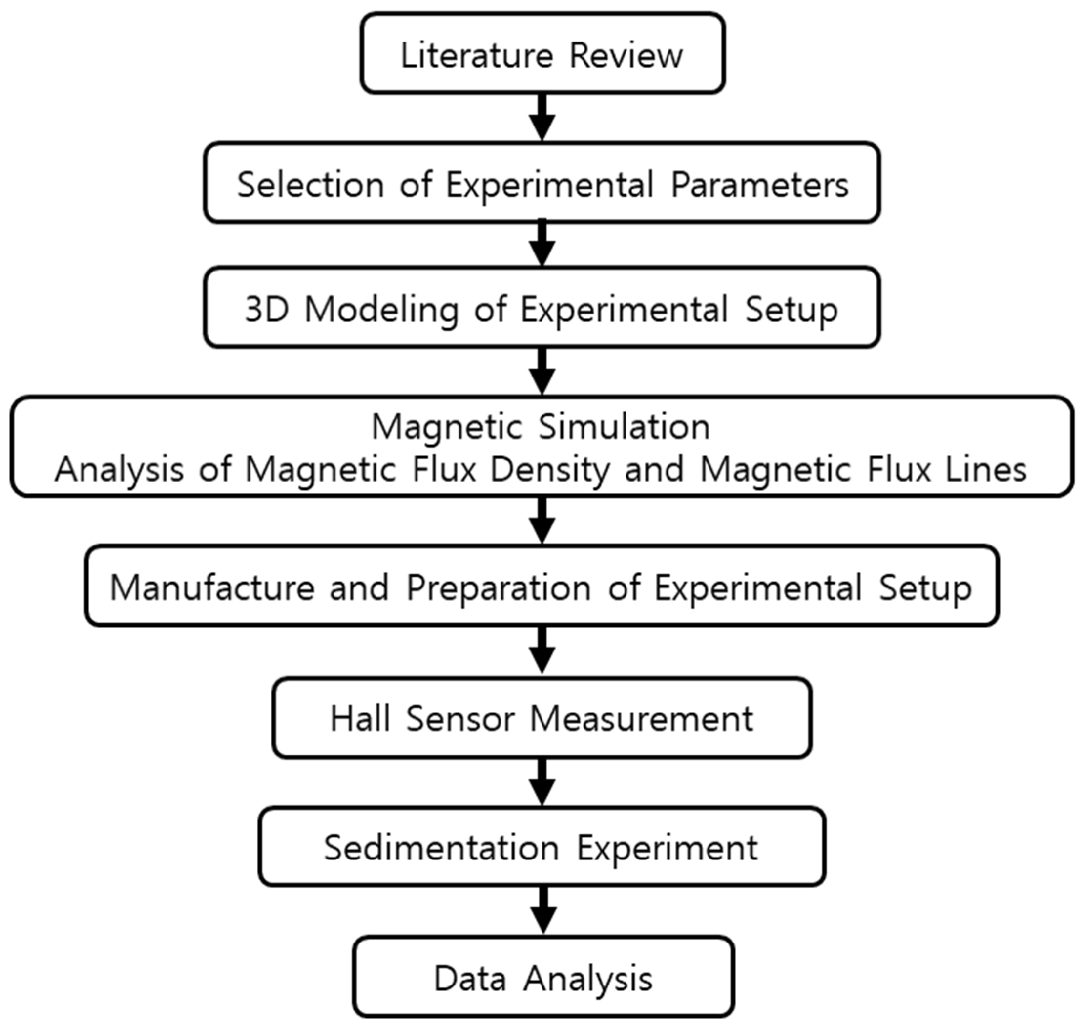
2. Materials and Methods

2.1. Magnetic Analysis

The transient magnetic simulation was conducted using the software ANSYS 2023 R2 Maxwell to confirm the generated magnetic flux density and the flux lines region. The generated magnetic flux path from the electromagnetic circuit should be uniformly formed around the MR fluids. The initial stage of the simulation was designing the geometry in a cross-section model depicted in Figure 2, with the details of parameters as shown in Table 1. By adding the air gap between the MR fluids and the magnetic circuit, it can decrease the resistance of the magnetic circuit which can increase the magnetic flux density around the gap. Subsequently, the boundary, excitations, and mesh were assigned to the simulation to acquire the analysis result of the magnetic fields. Steel 1008 was chosen as the material for the magnetic circuit. In addition, a copper wire with a diameter of 1 mm was wound approximately 500 turns around the steel bobbin. Commercialized MR fluids 132-DG by LORD Corporation, which have typical properties and magnetic properties that can be seen in Table 2 and Figure 3, were also added. The measuring tube was made from borosilicate glass. This was neglected since borosilicate glass is a non-magnetic material that is not typically susceptible to demagnetization when subjected to electromagnetic fields. In general, after being subjected to the electromagnetic field, it may not affect the demagnetization of the MR fluids. A similar magnetic simulation condition was also conducted by P.J. Widodo et al. [27], which did not take this into account in the magnetic simulation.
Figure 4 portrays the different colors of the results representing the strength of the generated electromagnetic field. The simulation was performed in four different currents (0.5 A, 1 A, 1.5 A, and 2 A) with the generated magnetic flux density around the MR fluids of 0.044 T, 0.069 T, 0.111 T, and 0.150 T, respectively. By increasing the current input, the magnetic flux density gets stronger. The lines that are shown in Figure 4 depict the covered area of the magnetic flux within the magnetic circuit and MR fluids. A weak generated magnetic flux density was also not found around the MR fluids region. Therefore, the experimental setup and parameters of this study were conducted as the magnetic simulation for the optimum MR effect.

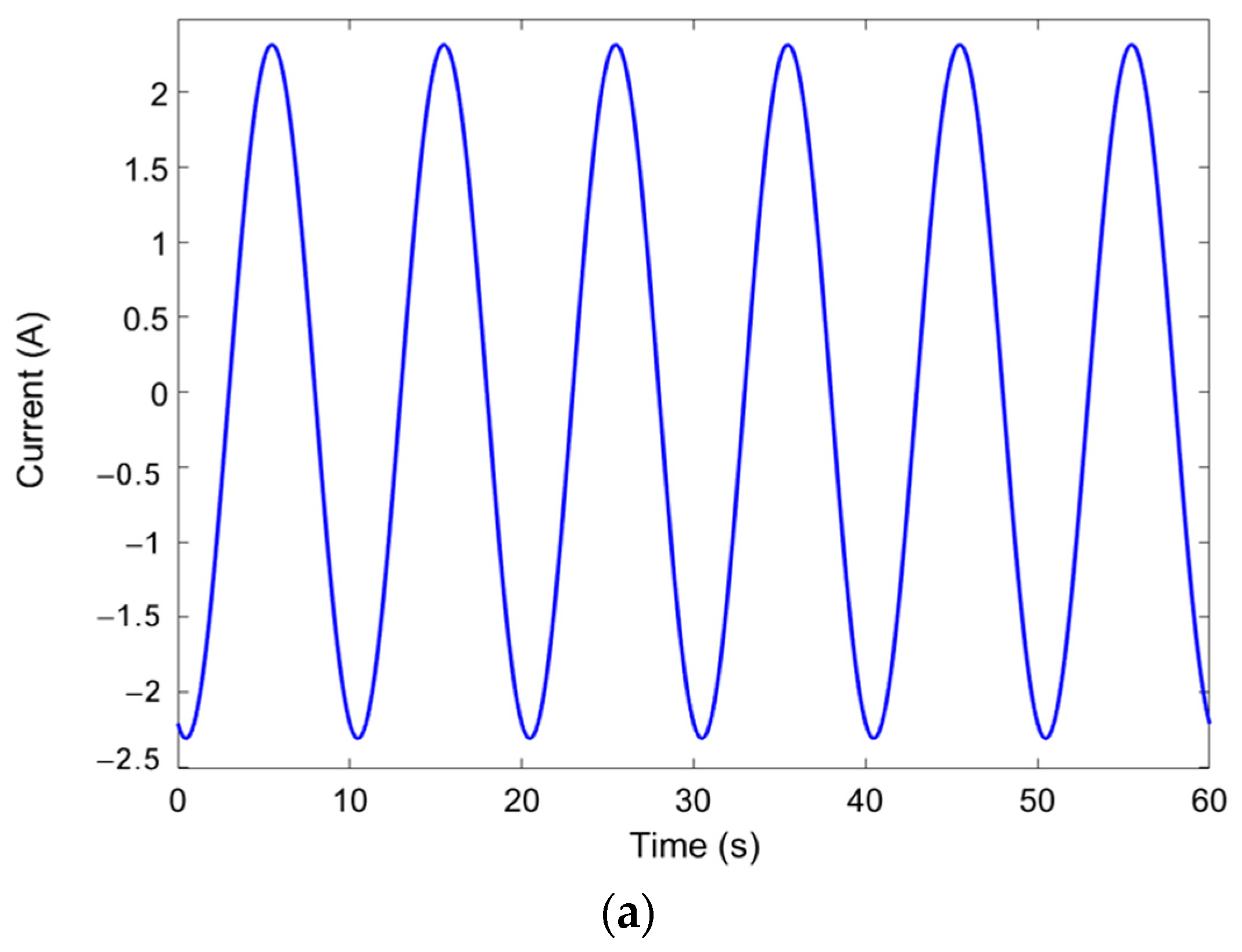
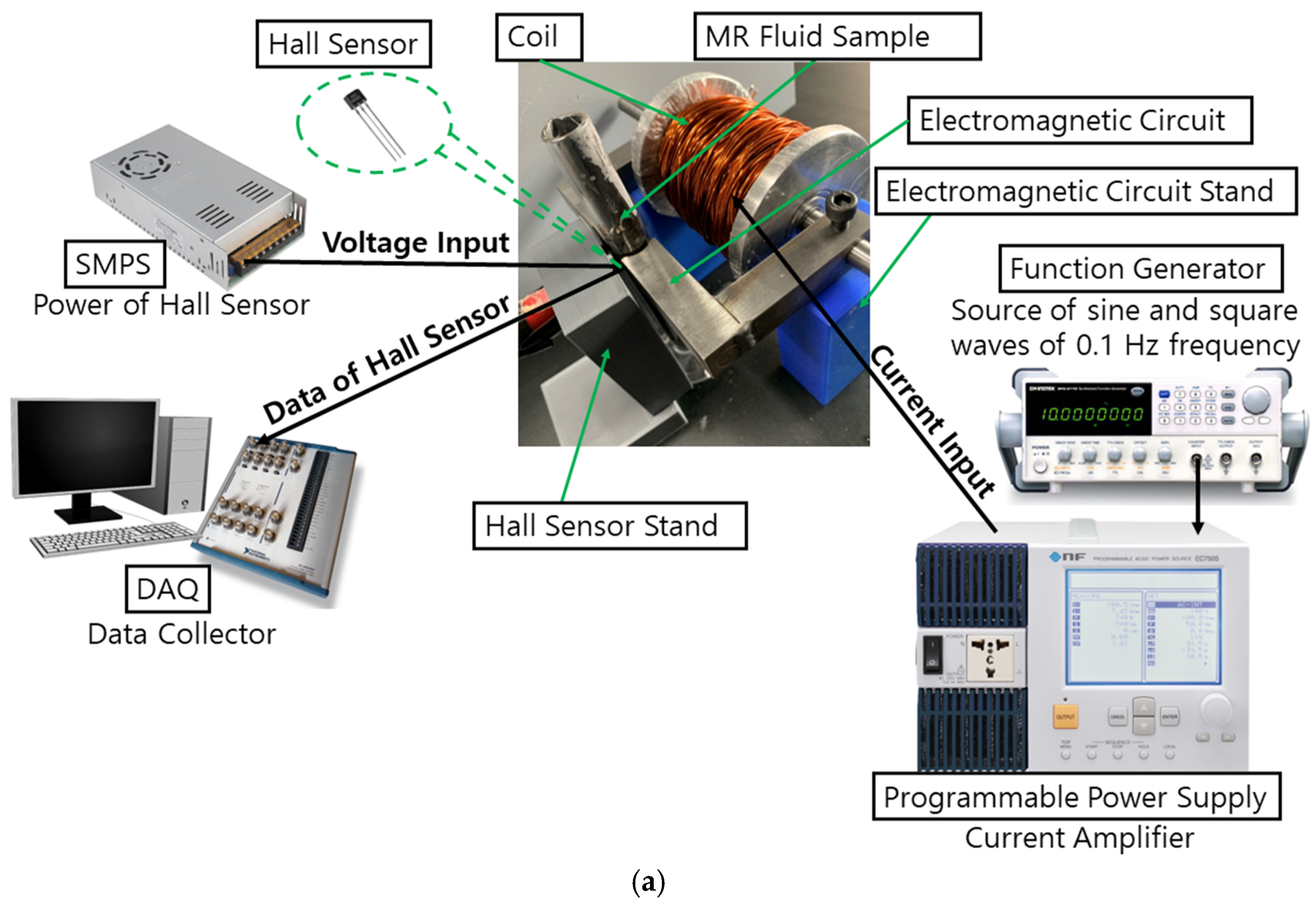
2.2. Experimental Method

This experimental study was conducted following Figure 5. It is noted that sedimentation happens when the iron particles settle against the surface of the fluids over time because of gravitational forces. Since the application of the MR effect can be controlled in only milliseconds, influencing iron particles using electromagnetic fields can improve sedimentation stability. The current inputs of 0.5 A, 1 A, 1.5 A, and 2 A were chosen based on the optimum current input intensity for the applications of MR fluids 132-DG such as MR dampers, which are usually subjected to a range current input of 0.5 A until 2 A, with a maximum generated magnetic flux density around 0.2 Tesla [28]. However, it can be noted that the effectiveness and the minimum threshold needed regarding the sedimentation may be different for each type of MR fluid since different MR fluid types have their own composition properties.
A low frequency was also considered as an experimental parameter. In general, low-frequency waves have fewer oscillations occurring within a given period. This frequency of magnetic field may result in a controlled sedimentation process since the profile of settling particles is necessary to be observed. This slow rate of oscillation allows for detailed observation and analysis of the settling particles’ profile without inducing rapid changes or disturbances. It should be noted that the DC excitation was not considered in this study since this study refers to the testing parameter on the application of MR fluids such as MR dampers, which are carried out under sinusoidal loading at a certain displacement, amplitude, and frequency [29,30]. Therefore, the experiment of this study was conducted with ten different testing parameters considering the various current input intensities, wave excitation, and diameter of the measuring tube (13 mm and 15 mm), which can be seen in Table 3 and Table 4.
Before starting the experiment, the MR fluids were shaken with our hands for about 30 min to avoid any residual sedimentation. The evaluation was carried out comparing the sedimentation rate through visual observation. The indication of sedimentation was concluded after the iron particles that were against the surface of carrier fluids (sedimentation layer) were seen. Each sample’s sedimentation layer was monitored and measured continuously for two weeks (336 h), with observations taken every 24 h. Then, the height of the sedimentation layer was estimated using a plastic ruler and measured multiple times for validation. The visual observation of the sedimentation layer is the most popular method to evaluate the sedimentation of MR fluids as reported in many studies [31,32,33,34] and the following Equation (1) was used to obtain the sedimentation rate.
S R   % = H s H M R F × 100 %
where SR is the sedimentation rate, HS is the height of the sedimentation layer, and HMRF is the total height of the MR fluids. Since the sedimentation starts from the top position, the sedimentation layer was evaluated for the top position of the measuring tube.
In this study, a programmable power supply (NF. EC750SA, Programmable AC/DC Power Source, NF Corporation, Inc., Yokohama, Japan) was used to control the current input and wave types. The setting output was set to AC+DC-EXT since the signals of sine and square waves with a low frequency were generated from the function generator (GW INSTEK SFG-2104) and can be amplified using this mode. The outputs of the current from the power supply at 2 A of the sine and square waves are shown in Figure 6a and Figure 6b, respectively. The sine and square waves were compared by RMS value, which can be calculated using Equations (2) and (3), respectively [35].
I r m s = 0.707 I p e a k
I r m s = I p e a k
where I r m s is the RMS value of the current and I p e a k is the peak value of the current. The obtained value of the sinusoidal wave was 1.56 A, while the square wave was 2.39 A.
In addition, a hall sensor measurement was utilized as the measuring tool for monitoring the generated electromagnetic fields. The measuring range of the hall sensor is from −10 V to +10 V, which is associated with the strength of the magnetic fields. Since the sedimentation experiment required a long duration, the hall sensor measurement was conducted at the initial stage of the experiment, as seen in Figure 7a to collect 60 s of sample data, which is sufficient for the data analysis. A hall sensor that was connected to a data acquisition system (DAQ National Instruments USB-6341-BNC), as seen in Figure 7b, received power from a 5V switching mode power supply (SMPS).
Since the sedimentation of iron particles occurs from the surface to the bottom, the magnetic circuit was placed on the top position of the measuring tube with a total height of 100 mm. By applying the magnetic field around the top position of the experimental tube, the iron particles may not freely disperse to the bottom part of the measuring tube. Then, the changed concentration of the sedimentation profile over time could be observed. The final experimental setup of this work (Figure 7c) was prepared by connecting the function generator and power supply to the coil. It can be noted that the shape of the magnetic circuit on the experimental setup was modified with the changeable length of the magnetic core due to the manufacturability factor and the experimental condition to maintain the 2 mm air gap since the experimental parameters were conducted with two different diameters.

3. Results and Discussion

3.1. Hall Sensor Measurement

A study by K.P. Lijesh et al. [23] placed four hall sensors near MR fluids with a permanent magnet at some distance to evaluate the settling particles. By placing the MR fluid sample far from the permanent magnet, the permeability of the medium between the sensor and magnet is changed from air to MR fluids, which increases the induced magnetic field in the sensor. Another study by J. Roupec et al. [25] utilized a hall probe that was covered by a thick brass plate to obtain the sedimentation rate. The thick brass had a relative permeability of 1 to prevent the hall probe from getting affected by the magnetic field and could measure the magnetic flux of the iron particles. On the other hand, this work utilized a hall sensor for a different purpose to monitor the output wave signals and electromagnetic fields. The measurement was conducted in analog output. The output signal of the hall sensor is amplified with the voltage output which is proportional to the magnetic field crossing the hall sensor. The voltage readings by the hall sensor were then converted to the CGS unit of magnetic field intensity (Gauss) using the typical voltage characteristics of the hall sensor which was around 1100 Gauss. The data were taken at the highest current input of 2 A using the DAQ, as shown in Figure 8. The signal output was formed in square wave and sine wave as power supply output to the coil, with the highest obtained magnetic flux density around 0.11 T.

3.2. Sedimentation Rate

The comparison results according to the wave types and current input intensity using the small tube can be seen in Figure 9. In addition, Figure 10 depicts the sedimentation layer of small tube samples.
It is shown that the sample without any waves and current input influence (baseline) took 48 h to start the sedimentation. The sedimentation rate of the baseline sample reached the value of 99% and ended up at around 93%. This was followed by the sample with the current of 1 A under the sine wave and square wave, which started the sedimentation after 72 h with a similar value of 99% and ended at the value of around 95.5% and 97%, respectively. The obtained average value of the sedimentation rate of the baseline (0 A), sine wave (1 A), and square wave (1 A) was 95.83%, 97.83%, and 98.61%, respectively. It can be concluded that the current excitation of the square wave affected a slower settling process. As the current signal explained in Section 2.2, the RMS value of the square wave was higher than the sine wave, which could be affecting the slower sedimentation process for the square wave excitation. Interestingly, the sedimentation rate of 2 A after 336 h for both the sine wave and square wave remained stable at 100% and did not show any sedimentation layer as seen in Figure 10. This was caused by the stronger chain-like structure in a parallel direction as the high value of generated electromagnetic fields. Under these conditions, it was hard for iron particles to settle down to the bottom, as illustrated in Figure 11. More specifically, the MR fluid operating mode under a magnetic field is within milliseconds (real time). As in a previous study by K. Shah et al. [16], the response time of MR fluids based on plate-like iron was 0.035 s after the magnetic field was applied and returned to its original state in 0.065 s after the removal of the magnetic fields. Therefore, when the electromagnetic fields were applied during the experiment time (non-stop), the iron particles remained in chain-like structures until they were removed.
To verify the minimum current input that could prevent sedimentation, another comparison is delivered in Figure 12, representing the sedimentation rate under sine wave at the frequency of 0.1 Hz and different current input intensities. The average value of the sedimentation rate for each current input was 95.98% (0 A), 97.13% (0.5 A), 97.83% (1 A), 100% (1.5 A), and 100% (2 A). It is noted that the current input of 1.5 A is sufficient to prevent the occurrence of sedimentation. The tendency of sedimentation remained constant (100%) from the start of the experiment until 336 h of the experiment. As shown in Figure 10, the sample with the current input of 1.5 A did not show any sedimentation layer. In general, the higher applied current input will slow down the process of sedimentation.
The other purpose of this study is also to compare the effect of the diameter on sedimentation. For this purpose, the sedimentation rate comparison is depicted in Figure 13. The sedimentation layer of each sample of the small tube (13 mm) can be seen in Figure 10, while the big tube (15 mm) can be seen in Figure 14. The small tube with the current input of 2 A did not show any changes in the sedimentation rate, remaining stable at 100%, while the big tube (15 mm) started the sedimentation after 48 h of the experiment with a value of around 99.8% and ended up at 96.4%. The average sedimentation rate of small tubes was 95.98% (0 A), 97.83% (1 A), and 100% (2 A). Meanwhile, the average sedimentation rate of the big tube was 95.45% (0 A), 97.19% (1 A), and 98.27% (2 A). Generally, the tendency lines showed that the big tubes had the faster sedimentation for all current input intensities. This study strengthens the assumption of a previous study by Roupec et al. [25] that exhibits the difference between their study and the study of Xie et al. [36] in sedimentation rate according to diameter of the tube. On the same experimental duration of 365 days (8760 h), Roupec used a tube with a diameter of 31.6 mm, while Xie used a tube with a diameter of 25 mm, which resulted in a sedimentation rate of 67% and 70%, respectively. The sedimentation for smaller diameters can happen slower since the particles are hindered by the walls by the imposition of no-slip conditions [26].

4. Conclusions

In this work, a magnetic circuit with 500 turns of a wounded coil was placed on the top position of a measuring tube to influence iron particles to not easily settle down to the bottom. The experiment was conducted under different current input intensities (0 A, 0.5 A, 1 A, 1.5 A, and 2 A), current wave types (square wave and sine wave), and diameters of the measuring tube (13 mm and 15 mm). Based on the experimental results and investigation of the sedimentation rate, the conclusions are summarized as follows:
(1)
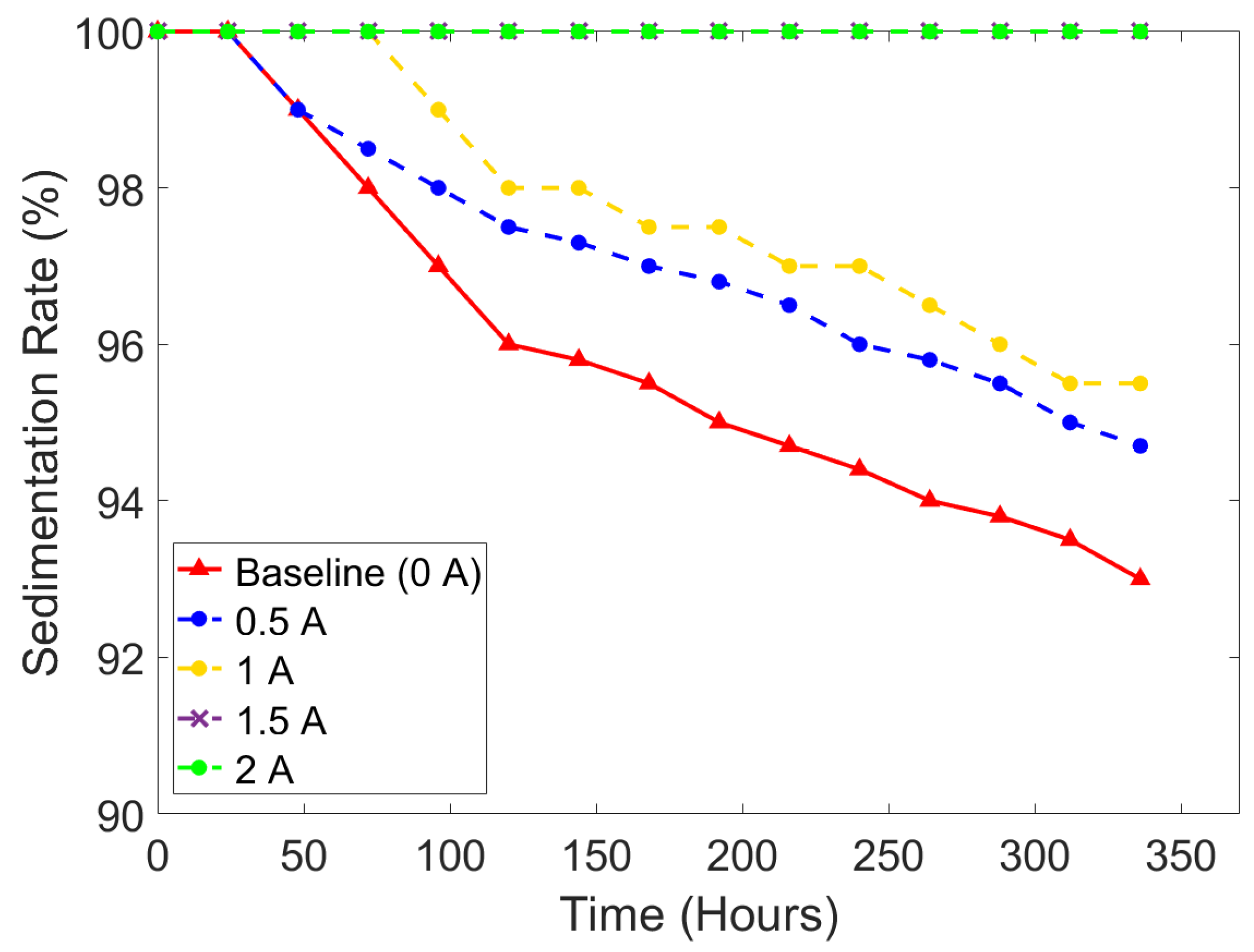
The square current wave shows slower sedimentation compared to the sine wave. When the intensity of 1 A current input was applied, the average sedimentation rate under the square wave was observed at 98.61%, while the average sedimentation rate under the square wave was 97.83%.
(2)
The higher intensity of the applied current input resulted in a stronger electromagnetic field, which could slow down the sedimentation of MR fluids caused by the strongly formed chain-like structure. The minimum current input for preventing sedimentation was identified as 1.5 A, which generated magnetic flux density around 0.073 T.
(3)
The walls on the smaller tube diameter could hinder the movement of the particles resulting in slowing down the sedimentation rate.
Even though some meaningful results have been achieved in this experimental study, the observed phenomena in real application systems should be further explored for more accurate validation. In other words, the investigation of the sedimentation behavior in the surface finishing or the field-dependent damping force by applying different current magnitudes and different input profiles with small and large diameter channels needs to be observed and analyzed in the near future. In addition, the parameter regarding the effect of high frequency on MR fluids sedimentation is an interesting topic to be conducted for future work.

Author Contributions

Conceptualization, E.T.M., M.-W.S., J.-S.O. and S.-B.C.; methodology, E.T.M., M.-W.S., J.-S.O. and S.-B.C.; software, E.T.M. and M.-W.S.; validation, E.T.M., M.-W.S., J.W.S., J.-S.O. and S.-B.C.; formal analysis, E.T.M., J.-S.O. and S.-B.C.; investigation, E.T.M.; resources, E.T.M., J.-S.O. and S.-B.C.; data curation, E.T.M. and J.-S.O.; writing—original draft preparation, E.T.M.; writing—review and editing, E.T.M., J.-S.O., J.W.S. and S.-B.C.; visualization, E.T.M.; supervision, J.-S.O. and S.-B.C.; project administration, M.-W.S. and J.-S.O.; funding acquisition, J.-S.O. and S.-B.C. All authors have read and agreed to the published version of the manuscript.

Funding

This research was supported by Cooperative Research Method and Safety Management 400 Technology in National Disaster (RS-2023-00253298) funded by Ministry of Interior and Safety 401 (MOIS, Korea).

Institutional Review Board Statement

Not applicable.

Informed Consent Statement

Not applicable.

Data Availability Statement

The data used to support the findings of this study are included within the article.

Conflicts of Interest

The authors declare no conflicts of interest.

References

  1. Ashtiani, M.; Hashemabadi, S.H.; Ghaffari, A. A review on the magnetorheological fluid preparation and stabilization. J. Magn. Magn. Mater. 2015, 374, 711–715. [Google Scholar] [CrossRef]
  2. Singh, A.; Kumar Thakur, M.; Sarkar, C. Design and development of a wedge shaped magnetorheological clutch. Proc. Inst. Mech. Eng. Part L J. Mater. Des. Appl. 2020, 234, 1252–1266. [Google Scholar] [CrossRef]
  3. Hidayatullah, F.H.; Ubaidillah, U.; Purnomo, E.D.; Tjahjana, D.D.D.P.; Wiranto, I.B. Design and simulation of a combined serpentine T-shape magnetorheological brake. Indones. J. Electr. Eng. Comput. Sci. 2019, 13, 1221–1227. [Google Scholar] [CrossRef]
  4. Oh, J.S.; Shin, Y.J.; Koo, H.W.; Kim, H.C.; Park, J.H.; Choi, S.B. Vibration control of a semi-active railway vehicle suspension with magneto-rheological dampers. Adv. Mech. Eng. 2016, 8, 1–13. [Google Scholar] [CrossRef]
  5. Ahmadian, M.; Southern, B.M. Isolation properties of low-profile magnetorheological fluid mounts. Fluids 2021, 6, 164. [Google Scholar] [CrossRef]
  6. Kordonski, W.I.; Shorey, A.B.; Tricard, M. Magnetorheological Jet (MR JetTM) Finishing Technology. J. Fluids Eng. 2006, 128, 20–26. [Google Scholar] [CrossRef]
  7. Kim, W.-B.; Nam, E.-S.; Min, B.-K.; Choi, D.-S.; Je, T.-J.; Jeon, E.-C. Material removal of glass by magnetorheological fluid jet. Int. J. Precis. Eng. Manuf. 2015, 16, 629–637. [Google Scholar] [CrossRef]
  8. Park, Y.J.; Choi, S.B. A new tactile transfer cell using magnetorheological materials for robot-assisted minimally invasive surgery. Sensors 2021, 21, 3034. [Google Scholar] [CrossRef] [PubMed]
  9. Ganapathy Srinivasan, R.; Shanmugan, S.; Palani, S. Application of magnetorheological fluid in machining process. Int. J. Control Theory Appl. 2016, 9, 3705–3712. [Google Scholar]
  10. Lu, H.; Hua, D.; Wang, B.; Liu, H.; Yang, C.; Hnydiuk-Stefan, A. The Roles of Magnetorheological Fluid in Modern Precision Machining Field: A Review. Front. Mater. 2021, 8, 678882. [Google Scholar] [CrossRef]
  11. Girinath, B.; Mathew, A.; Babu, J.; Thanikachalam, J.; Bose, S.S. Improvement of Surface Finish and Reduction of Tool Wear during Hard Turning of AISI D3 using Magnetorheological Damper. J. Sci. Ind. Res. 2018, 77, 35–40. [Google Scholar]
  12. Mutalib, N.A.; Ismail, I.; Soffie, S.M.; Aqida, S.N. Magnetorheological finishing on metal surface: A review. IOP Conf. Ser. Mater. Sci. Eng. 2019, 469, 012092. [Google Scholar] [CrossRef]
  13. Gorodkin, S.R.; Kordonski, W.I.; Medvedeva, E.V.; Novikova, Z.A.; Shorey, A.B. A method and device for measurement of a sedimentation constant of magnetorheological fluids. Rev. Sci. Instrum. 2000, 71, 2476–2480. [Google Scholar] [CrossRef]
  14. Kumar Kariganaur, A.; Kumar, H.; Arun, M. Effect of temperature on sedimentation stability and flow characteristics of magnetorheological fluids with damper as the performance analyser. J. Magn. Magn. Mater. 2022, 555, 169342. [Google Scholar] [CrossRef]
  15. Choi, S.-B. Sedimentation Stability of Magnetorheological Fluids: The State of the Art and Challenging Issues. Micromachines 2022, 13, 1904. [Google Scholar] [CrossRef] [PubMed]
  16. Shah, K.; Phu, D.X.; Seong, M.S.; Upadhyay, R.V.; Choi, S.B. A low sedimentation magnetorheological fluid based on plate-like iron particles, and verification using a damper test. Smart Mater. Struct. 2014, 23, 027001. [Google Scholar] [CrossRef]
  17. Zhibin, S.; Yiping, L.; Ying, W.; Jiao, L.; Dongsheng, J. Study on sedimentation stability of magnetorheological fluids based on different lubricant formulations. Mater. Res. Express 2020, 7, 085702. [Google Scholar] [CrossRef]
  18. Cheng, H.; Wang, M.; Liu, C.; Wereley, N.M. Improving sedimentation stability of magnetorheological fluids using an organic molecular particle coating. Smart Mater. Struct. 2018, 27, 075030. [Google Scholar] [CrossRef]
  19. Morillas, J.R.; de Vicente, J. Magnetorheology: A review. Soft Matter 2020, 16, 9614–9642. [Google Scholar] [CrossRef]
  20. Singh, H.; Singh Gill, H.; Sehgal, S.S. Synthesis and Sedimentation Analysis of Magneto Rheological Fluids. Indian J. Sci. Technol. 2016, 9, 210. [Google Scholar] [CrossRef]
  21. Thiagarajan, S.; Koh, A.S. Performance and Stability of Magnetorheological Fluids—A Detailed Review of the State of the Art. Adv. Eng. Mater. 2021, 23, 2001458. [Google Scholar] [CrossRef]
  22. Hong, K.P.; Song, K.H.; Cho, M.W.; Kwon, S.H.; Choi, H.J. Magnetorheological properties and polishing characteristics of silica-coated carbonyl iron magnetorheological fluid. J. Intell. Mater. Syst. Struct. 2018, 29, 137–146. [Google Scholar] [CrossRef]
  23. Lijesh, K.P.; Muzakkir, S.M.; Hirani, H. Rheological measurement of redispersibility and settling to analyze the effect of surfactants on MR particles. Tribol.–Mater. Surf. Interfaces 2016, 10, 53–62. [Google Scholar] [CrossRef]
  24. López-López, M.T.; de Vicente, J.; Bossis, G.; González-Caballero, F.; Durán, J.D.G. Preparation of stable magnetorheological fluids based on extremely bimodal iron–magnetite suspensions. J. Mater. Res. 2005, 20, 874–881. [Google Scholar] [CrossRef]
  25. Roupec, J.; Berka, P.; Mazůrek, I.; Strecker, Z.; Kubík, M.; Macháček, O.; Taheri Andani, M. A novel method for measurement of MR fluid sedimentation and its experimental verification. Smart Mater. Struct. 2017, 26, 107001. [Google Scholar] [CrossRef]
  26. Heitkam, S.; Yoshitake, Y.; Toquet, F.; Langevin, D.; Salonen, A. Speeding up of sedimentation under confinement. Phys. Rev. Lett. 2013, 110, 178302. [Google Scholar] [CrossRef]
  27. Widodo, P.J.; Budiana, E.P.; Ubaidillah, U.; Imaduddin, F. Magnetically-induced pressure generation in magnetorheological fluids under the influence of magnetic fields. Appl. Sci. 2021, 11, 9807. [Google Scholar] [CrossRef]
  28. Kubík, M.; Goldasz, J. Multiphysics Model of an MR Damper including Magnetic Hysteresis. Shock Vib. 2019, 2019, 3246915. [Google Scholar] [CrossRef]
  29. Maharani, E.T.; Ubaidillah, U.; Imaduddin, F.; Wibowo, W.; Utami, D.; Mazlan, S.A. A mathematical modelling and experimental study of annular-radial type magnetorheological damper. Int. J. Appl. Electromagn. Mech. 2021, 66, 543–560. [Google Scholar] [CrossRef]
  30. Li, W.H.; Yao, G.Z.; Chen, G.; Yeo, S.H.; Yap, F.F. Testing and steady state modeling of a linear MR damper under sinusoidal loading. Smart Mater. Struct. 2000, 9, 95–102. [Google Scholar] [CrossRef]
  31. Leong, S.A.N.; Mazlan, S.A.; Samin, P.M.; Idris, A.; Ubaidillah, U. Performance of bidisperse magnetorheological fluids utilizing superparamagnetic maghemite nanoparticles. AIP Conf. Proc. 2016, 1710, 030050. [Google Scholar]
  32. Aruna, M.N.; Rsahman, M.R.; Joladarashi, S.; Kumar, H.; Devadas Bhat, P. Influence of different fumed silica as thixotropic additive on carbonyl particles magnetorheological fluids for sedimentation effects. J. Magn. Magn. Mater. 2021, 529, 167910. [Google Scholar] [CrossRef]
  33. Aruna, M.N.; Rahman, M.R.; Joladarashi, S.; Kumar, H. Investigation of sedimentation, rheological, and damping force characteristics of carbonyl iron magnetorheological fluid with/without additives. J. Braz. Soc. Mech. Sci. Eng. 2020, 42, 228. [Google Scholar] [CrossRef]
  34. Zhu, W.; Dong, X.; Huang, H.; Qi, M. Iron nanoparticles-based magnetorheological fluids: A balance between MR effect and sedimentation stability. J. Magn. Magn. Mater. 2019, 491, 165556. [Google Scholar] [CrossRef]
  35. Rawlins, J.C. Basic AC Circuit, 2nd ed.; Butterworth–Heinemann: Woburn, MA, USA, 2000; pp. 29–63. [Google Scholar]
  36. Xie, L.; Choi, Y.-T.; Liao, C.-R.; Wereley, N.M. Long term stability of magnetorheological fluids using high viscosity linear polysiloxane carrier fluids. Smart Mater. Struct. 2016, 25, 075006. [Google Scholar] [CrossRef]
Figure 1. The schematic of surface precision machining.
Magnetochemistry 10 00018 g001
Figure 2. Cross-section model of experimental setup.
Magnetochemistry 10 00018 g002
Figure 3. B-H curve of MR fluids 132-DG.
Magnetochemistry 10 00018 g003
Figure 4. The result of the magnetic field analysis in a different current input, (a) 0.5 A, (b) 1 A, (c) 1.5 A, (d) 2 A.
Magnetochemistry 10 00018 g004
Figure 5. Flow diagram of experimental study.
Magnetochemistry 10 00018 g005
Figure 6. Output signal of power supply (a) sine wave excitation, (b) square wave excitation.
Magnetochemistry 10 00018 g006aMagnetochemistry 10 00018 g006b
Figure 7. Experimental setup, (a) initial stage of experimental setup, (b) front view of hall sensor, (c) front view of the final experimental setup.
Magnetochemistry 10 00018 g007aMagnetochemistry 10 00018 g007b
Figure 8. The calibrated value of the CGS unit of magnetic field intensity by the hall sensor at a current input of 2 A under (a) sine wave excitation, (b) square wave excitation.
Magnetochemistry 10 00018 g008
Figure 9. The comparison of sedimentation rate according to wave types and current input intensity using the small tube.
Magnetochemistry 10 00018 g009
Figure 10. MR fluids samples for small measuring tube: (a) initial condition (0 h); (b) 0 A (336 h); (c) sine wave, 0.5 A (336 h); (d) sine wave, 1 A (336 h); (e) sine wave, 1.5 A (336 h); (f) sine wave, 2 A (336 h); (g) square wave, 1 A (336 h); (h) square wave, 2 A (336 h).
Magnetochemistry 10 00018 g010
Figure 11. The distribution of iron particles under exciting electromagnetic fields.
Magnetochemistry 10 00018 g011
Figure 12. The comparison of sedimentation rate according to different current input intensities under sine wave using the small tube.
Magnetochemistry 10 00018 g012
Figure 13. The comparison of sedimentation rate according to different current input intensities under sine wave using the small tube and big tube.
Magnetochemistry 10 00018 g013
Figure 14. MR fluid samples for big measuring tube, (a) initial condition (0 h), (b) 0 A (336 h), (c) sine wave, 1 A (336 h), (d) sine wave, 2 A (336 h).
Magnetochemistry 10 00018 g014
Table 1. Parameters of cross-section model of experimental setup.
ParametersDescriptionValueUnit
WMagnetic Core Width19mm
LMagnetic Core Length 118mm
l1Magnetic Core Length 150.5mm
l2Magnetic Core Length 288mm
R1Bobbin Outer Radius 135mm
R2Bobbin Inner Radius 210mm
laBobbin Total Length 78mm
lbBobbin Length64mm
rCoil Radius 0.5mm
NCoil Winding 500turns
SairAir Gap Length 2mm
DtMR Fluids Diameter15mm
Table 2. The typical properties of MR fluids 132-DG.
ParametersValueUnit
Viscosity0.112Pa·s
Density2.95–3.15g/cm3
Solid Content by Weight80.90W%
Flash Point>150°C
Temperature−40 to +130°C
Table 3. Experimental parameters for the small tube diameter (13 mm).
Wave TypeCurrent InputFrequency
Baseline--
Sine Wave0.5 A0.1 Hz
Sine Wave1 A0.1 Hz
Sine Wave1.5 A0.1 Hz
Sine Wave2 A0.1 Hz
Square Wave 10.1 Hz
Square Wave2A0.1 Hz
Table 4. Experimental parameters for the big tube diameter (15 mm).
Wave TypeCurrent InputFrequency
Baseline--
Sine Wave1 A0.1 Hz
Sine Wave2 A0.1 Hz
Disclaimer/Publisher’s Note: The statements, opinions and data contained in all publications are solely those of the individual author(s) and contributor(s) and not of MDPI and/or the editor(s). MDPI and/or the editor(s) disclaim responsibility for any injury to people or property resulting from any ideas, methods, instructions or products referred to in the content.

