Abstract
Today, there are new technologies to produce bioethanol: one of them is the Pressure Swing Adsorption (PSA) process. This process has displaced other separation technologies due to the use of natural adsorbents and its methodology to obtain high purities with a lower energy cost. The aim of this work focuses on the optimization of the PSA process (experimental case) to obtain a higher recovery and production of bioethanol using lower energy consumption. The results are favorable since the energy cost is reduced to a range of 60% and 62%, obtaining purities above 99% wt of ethanol and recovery between 75% and 77.41%. The bioethanol produced and purified in the different scenarios meets international standards to be used as a fuel or oxygenating additive.
1. Introduction
The Pressure Swing Adsorption (PSA) process is used in different gas separation processes, among which ethanol dehydration stands out. It is one of the separation technologies with great potential for the production of biofuel, obtaining high degrees of purity of bioethanol [1].
The advantage of the PSA process lies in the use of zeolites (natural and synthetic types) since they do not contain residues of separating agents that can contaminate or diminish the purity of ethanol. Due to their physical and selective properties, the pores of zeolites that have a diameter of 3 Å (Angstrom) can retain water molecules (2.6 Å) on their surface, while ethanol molecules that have a diameter greater than 4 Å pass freely through them, allowing for obtaining only ethanol as a final product.
To predict and analyze the dynamic behavior of the PSA process is necessary mathematical modeling, represented by Partial Differential Equations (PDEs) that describe the cyclical dynamics of the PSA Process. Different numerical methods can obtain an approximation to this type of process. In [2,3], the use of different numerics methods can be observed for the PSA model. Likewise, Refs. [4,5,6,7] present a finite-volume method for temperature swing adsorption systems. Their method focuses on PSA processes on an industrial scale and proves to be capable of reproducing the characteristics of their systems with good computational efficiency.
The mathematical model can be obtained from data from an operating plant or previously performed analyses. Refs. [8,9] present a PSA mathematical model applied to ethanol dehydration, and the data were obtained from a real plant. On the other hand, the works presented by [10,11] show that it is possible to minimize the computational cost to find optimal values at the start-up of the PSA process.
The PSA process has stood out for its low energy costs and high efficiency. In part, this efficiency is because the process is carried out cyclically in two parallel columns [12]. In [13,14], they developed the optimization of the PSA process involving two parallel columns, and they implemented a mathematical model that describes the dynamics of the process and shows the decreases in ethanol purity that can affect a real pilot plant.
It is important to maintain stable 99% ethanol purity and comply with international standards; for this, it is necessary to design and implement controllers, with the aim of eliminating or attenuating the disturbances that occur in the PSA process [15].
Another theory, such as machine learning, can help in the optimization of this type of cyclical process. In [16,17], they demonstrated the efficacy of using artificial neural networks in a PSA model.
New techniques and variants of PSA models have recently been studied. In [18], two new techniques for vacuum or pressure swing adsorption are analyzed. These mathematical models demonstrate improvements in convergence stability to cyclical steady state (CSS) when pressure equalization steps are involved. Ref. [19] presents the use of surrogate models to address the computational requirements of the high-fidelity simulations necessary to evaluate alternative designs. These models obtain a five times reduction in computational effort compared to common models.
In recent years, new alternatives for the separation of mixtures have begun to be studied. The use of membranes has stood out as an efficient and fast method to generate bioethanol.
Ref. [20] analyzed and studied reactive membrane distillation for ethanol generation. Different membrane distillation alternatives were designed and simulated in this study. The results show that this method of separation of mixtures is an alternative of high interest due to its high efficiency and low energy consumption.
In [21], different types of molecular carbon sieve membranes were tested for an ethanol dehydration process via pervaporation. The results obtained were compared with membranes from other investigations. The membranes of the study improved the permanence of the water, in addition to having a greater selectivity against ethanol.
Recently, alternatives to generating bioethanol have been studied. These alternatives seek to cover other problems of the classic methods of ethanol purification such as high energy consumption and low production of biogas.
Different alternatives for bioethanol production to reduce energy demands and operating costs are discussed and analyzed in [22]. The results of the methods proposed in the research demonstrated to reduce the cost associated with energy consumption and decreased the total cost of production.
Simulations are designed in [23] to assess the efficiency of a cellulose biorefinery for dehydrating ethanol. This study showed that the method studied has a low rate of energy consumption while maintaining a high degree of production per year. However, it highlights the need for real studies to support its results. One of the applications of ethanol that has stood out recently is to produce hydrogen. In [24], they perform the study and analysis of a liquefaction process to produce bio-hydrogen from bio-ethanol. This method proved to be an alternative with a great capacity for improvement and should be further studied.
Other studies focus on implementing control methods to previously studied PSA systems. These control systems reduce operating time, greatly increase efficiency and in some cases also increase the degree of purity of ethanol.
In [25], four different methods were evaluated for reactive ethanol dehydration in a simulated PSA plant. The application of proportional-integral control systems was also evaluated. The data obtained show that including control systems for this type of process greatly reduces the time it takes the plant to reach stability. However, they highlight the difficulty of raising ethanol purity to very high levels when applying these methods.
In [26], they applied two methods for nonlinear control systems to a virtual PSA bioethanol generation plant. They showed that adding a control system considerably attenuates disturbances, thereby reducing the time it takes a plant to reach the cyclic stable state and preserving the desired purity level.
Process modeling can be simulated in different specialized programs [27,28]. For the present study, Aspen Adsorption is used for the simulation of the PSA process.
The contribution of this work is to optimize the PSA process and have greater production and recovery of bioethanol, reducing the energy cost demanded by the PSA process. The results obtained present outstanding data to scale the PSA plant or reduce it and have greater production and purification of bioethanol that meets international standards of purity to be used as fuel.
This work is divided as follows: Section 2 presents information on the scheme and parameters of the experimental study case, with the description of each of the input parameters, the number of steps, and the dimensioning characteristics of the PSA process. Section 3 presents information on the rigorous highly nonlinear mathematical model, with the description of each equation that describes the cyclical nature of the PSA process. In Section 4, the results obtained from the two schemes proposed for the solution of the problem of the experimental study case are presented, and, finally, in Section 5, the conclusions are shown.
2. Scheme and Parameters of the Experimental Study Case
A wide variety of parameters interfere with the degree of efficiency of the PSA model; these parameters are the flow rate, temperature, pressure and the initial composition of the mixture. The schematic design of this model and the column parameters are shown below:
The rigorous PSA model is based on PDEs. This study consists of two beds, 7.3 m high and 2.4 m in diameter. 10 reversible flow type valves: 3 used to feed the columns, 3 used for waste, 1 for purge, and 3 correspond to the product part (see Figure 1).
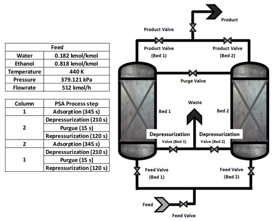
Figure 1.
Schematic design of the PSA process.
The feed composition of the water–ethanol mixture has a concentration close to the azeotropic point (8% wt of water and 92% wt of ethanol) 0.182 and 0.818 of molar fraction, at a temperature of 440 K (which must be kept constant) since the process works in the vapor phase. The pressure of the adsorption is 379.212 kPa, while the pressure in the regeneration stage is lower (13.79 kPa); this purge pressure facilitates the breaking of the weak bond formed by the absorbent and the water molecules. The present work aims to analyze the model proposed by [8]. Based on simulations carried out, the deficiencies that the PSA process (real plant) may present will be studied. The first study (study case 1) will present an analysis of the dynamic behavior of the PSA process using smaller columns (3.65 m in length and 2.4 m in diameter) with the same parameters present in the experimental study case [8]. For study case 2, the changes of some parameters that improve the adsorption capacity of the PSA process will be examined but using the same dimensions of the columns (7.3 m in length and 2.4 m in diameter) presented in [8]; this to obtain an optimal model that covers the deficiencies of the experimental study case and manages to adsorb along the maximum length of the columns to produce a greater amount of bio-ethanol.
The PSA process works with four steps. The first step (adsorption) corresponds to the production of ethanol; then, the regeneration of the zeolites is carried out, which corresponds to the following three steps: depressurization, purge, and repressurization. These steps are performed periodically and alternately in both columns. A schematic layout of the PSA steps is shown in Figure 2.
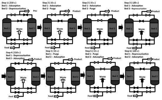
Figure 2.
Cycle of the PSA process.
The parameters for the experimental study case [8] are presented in Table 1.

Table 1.
Required parameters to the PSA process (experimental study case).
3. Mathematical Model of the PSA Process
The mathematical model describes the dynamics of the four-step cyclic process and the effects of the variables involved in the PSA process. The model PSA presents temperature, pressure, velocity, and composition profiles as a function of time and longitude bed. To have a practical description, the following assumptions were made for this model: The material balance is given by convection with constant dispersion and is represented by Equation (1). The process columns operate under non-isothermal with solid conduction energy balance. Equation (5) describes the energy balance of the model. Adsorption equilibrium is described by the Langmuir 1 model with isotherm dependency by partial pressure. In Equation (10), the isothermal parameters of the system are described. The pressure drop is specified by the Ergun Equation (12). The heat of adsorption and the form of the heat transfer coefficient are constant. Equation (11) describes that the kinetic model is designated by Lumped resistance with a linear model. With all of the above, the rigorous PSA model consists of the equations shown in Table A1.
3.1. Total Mass Balance
Equation (1) established to determine the amount of water molecule absorbed in each column:
where:
Convection term:
Term of accumulation of matter in the gas phase:
Flow over the solid surface:
3.2. Energy Balance
To determine the temperature increases in the bed, Equation (5) is applied:
where:
Axial thermal conductivity in the solid that depends on the conductivity of the zeolite.
Accumulation of energy in the solid:
Absorbent heat:
Solid-gas heat transfer depending on the coefficient of heat transfer and area heat transfer:
3.3. Adsorption Isotherm (Thermodynamic Model)
Equation (10) determines the adsorption isotherm (on the surface of a solid), this is described by the Langmuir model, which is characterized by the following points:
- The surface provides several locations for adsorption and they are all equivalent.
- Only one molecule is adsorbed on each position.
- Its adsorption is independent from the occupation of neighboring positions (the adsorbed molecules do not interact with each other):
3.4. LDF Approximation
The Linear Driving Force (LDF) is used with great frequency in the practical analysis of PSA models. The LDF model works for its performance in the separation of adsorption processes and for the cyclical levels of the stationary state, in addition to requiring the kinetic properties of the particle and the column studied [29]:
where:
Solid film mass transfer coefficient is and is the parameter in the Glueckauf expression.
3.5. Pressure Drop
Equation (12) is used to determine the pressure drops across the beds in adsorption systems. The data were obtained from [8]:
Solving such a complex model can be numerically intensive, generating computational cost. However, the correct modeling of the PSA process allows us to present the cyclic nature in the simulations and obtain approximate solutions for the real plant. To solve these PDEs, the initial and boundary conditions of the PSA process are necessary, which determine the initialization in each step (adsorption, depressurization, purge, and repressurization) of the process. The conditions for the first cycle in the two beds are shown in Table A1.
After a certain time, a CSS is reached, this is the nature of periodic adsorption processes in which its conditions at the end of the cycle are identical to those at the beginning of the cycle. Once the pseudo-steady state is reached, it is possible to observe the ”maximum performance” that the process can achieve. The time it takes for a model to reach CSS is different for each process and depends on the features and variables. In this case, the simulation of the process was carried out in Aspen Adsorption with the numerical method called Orthogonal Collocation on Finite Elements OCFE (see Appendix B).
4. Results and Discussion
This section shows the results of the comparisons of the two cases proposed to solve the experimental study case, with the aim of having an efficient, optimal, and high-performance PSA process for the separation and purification of bioethanol.
The model proposed by [8] applied to the PSA process is widely used for ethanol production since it is an experimental study (real data). However, the 7.3 m (longitude) and 2.4 m (diameter) beds do not adsorb water molecules in their entire length between 4 m and 7 m, causing these columns packed with zeolite type 3A not to be used to the maximum.
For this reason, this work will focus on the development and analysis of two case studies to improve deficiencies and obtain an optimal PSA process.
Study case 1 presents and analyzes the use of small beds in comparison with the experimental case study. These beds are 3.65 m long and use the same diameter (2.4 m). This dimensioning was used to observe their behavior and show that they adsorb the same amount of water as the 7.3 m beds. and produce ethanol to 99% ethanol by weight.
For study case 2, columns having the same length (7.3 m) and diameter (2.4 m) as the [8] case study are implemented and analyzed. In this case, parameters and data have been proposed that favor the columns, in such a way that they can be used in their greatest length (7.3 m) and be able to absorb a greater amount of water. In this case, higher productivity and recovery of anhydrous ethanol will be achieved.
4.1. Experimental Study Case
For this case of [8], the nominal values of the PSA process are shown in Table 1. Each of these parameters is used in the equations of the rigorous PSA model shown in Table A1; this model is used for determining the cyclical dynamic behavior of the process until its CSS is reached. This pseudo-steady state is the nature of the periodic adsorption process in which the profiles are the same from the start of the CSS to the end of the process.
Figure 3 shows the purity levels of experimental study case. Initially, the composition is 92% wt ethanol (0.818 molar fraction of ethanol) and 8% wt water (0.182 molar fraction of water). The ethanol–water mixture is pressurized to 379 kPa with a temperature of 440 K. Once this mixture comes into contact with the zeolite, rapid adsorption takes place. During the first few cycles, arbitrary purity profiles are observed. As the cycles pass, these profiles are regularized and approach the CSS. This regularization begins after 100 cycles (19 h); however, the purity percentages have not yet reached their stable point. The entire process takes 350 cycles (67 h) in the simulation until the CSS is reached.
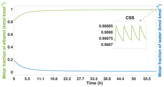
Figure 3.
Ethanol-water mixture purity profile from start-up to CSS, experimental study case.
Once this point is reached, the highest purity levels that the model can reach are 99.5% wt of ethanol; this is shown in Figure 3.
Temperature profiles can be seen in Figure 4 from start-up to CSS. Four profiles are observed located in four different nodes (5, 10, 15, and 20) equivalent to the longitudinal distance of the column. The temperature profiles become more stable when approaching the CSS, in the same way as the purity profiles due to the cyclical nature of the PSA process. Node 5 corresponds to the lowest part of the bed. In this part, the temperature profiles have the lowest levels, reaching 340 K. Once the CSS is reached, the profile stabilizes at 444 K. At node 10, a temperature decrement can be seen between the first 50 cycles (10 h), the same behavior seen in node 5. The temperature profiles in the middle of the bed present a more stable behavior at around 450 K.
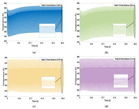
Figure 4.
Solid temperature profile from start-up to CSS. (a) Node 5; (b) Node 10; (c) Node 15; (d) Node 20.
In the bottom parts of the bed, nodes 5 and 10 showed a small increase in temperature in the first cycles. At this point, the temperature level is 459 K. At the top of the column, more stability in the temperature profiles (nodes 15 and 20) is observed, reaching 475 K. (see Figure 4).
During the regeneration, the lower parts of the column (nodes 1–5) have the highest temperature levels, due to the high concentration of water located in this part of the bed.
Figure 5, Figure 6, Figure 7 and Figure 8 show the purity, temperature, and pressure profiles throughout the bed during CSS.
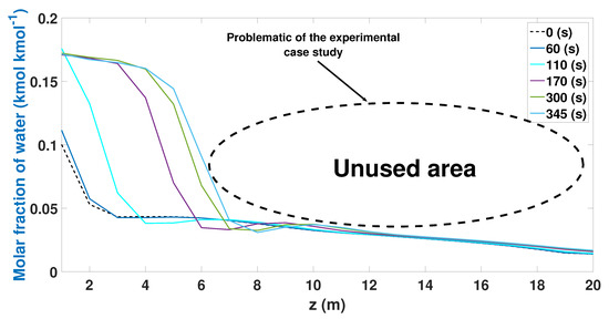
Figure 5.
Molar fraction of water during the adsorption stage from CSS.
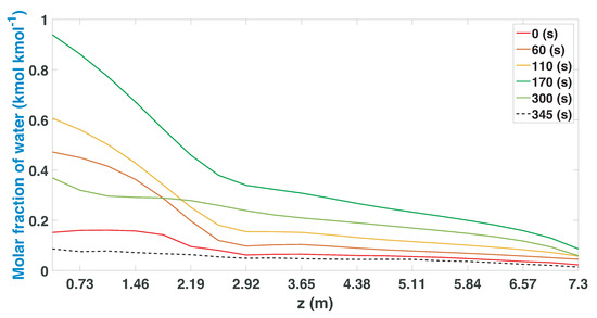
Figure 6.
Molar fraction of water during the regeneration stage from CSS.
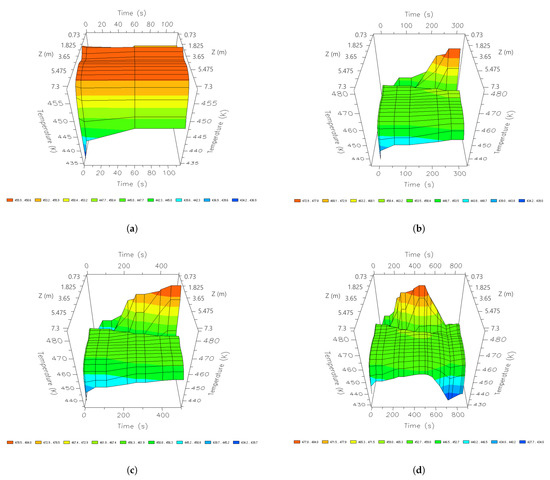
Figure 7.
Three-dimensional space graphics of the temperature profile along the bed in the CSS, different times of a cycle; (a) 60 s; (b) 210 s; (c) 345 s; and (d) 690 s.
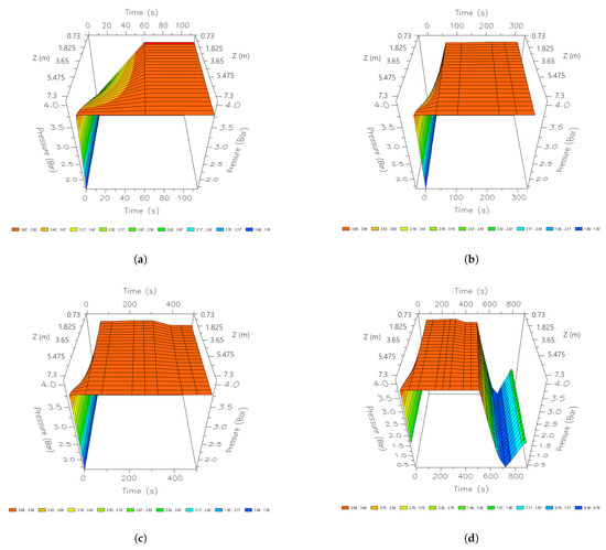
Figure 8.
Three-dimensional space graphics of the pressure profile along the bed in the CSS, different times of a cycle; (a) 60 s; (b) 210 s; (c) 345 s; and (d) 690 s.
Figure 5 shows the water profiles during the adsorption stage along the bed. The lowest profile is seen at the beginning of the stage (0 s). This profile increases over time, having its maximum profile at 345 s. The profile tends to increase as time increases during the adsorption stage. The adsorption of water shows a drop in the profiles between nodes 8 (2.92 m) and 10 (3.65 m) discretized length. The results show that the experimental study case uses less than 50% of the column to adsorb water. This waste represents a notable loss of efficiency in ethanol production and the energy cost of the PSA process. This deficiency can be due to different factors: the initial parameters (temperature, pressure, composition, and flow) are not optimal for the model or the chosen column is larger than what is required.
The regeneration stage is executed once the column completes the adsorption stage (Figure 6). At the beginning of the recovery, the column is depressurized and the temperature levels also drop; in this way, a greater quantity of water enters the column. In the middle of the regeneration process, the greatest amount of water enters; this profile begins to drop once the column is repressurized so that, at 345 s, the lowest water profile of all is found.
Figure 7 shows the dynamics of the temperature profile at different instants of time along the column. In the initial stages of the adsorption stage, most of the heat is concentrated between 1.825 m and 5.475 m reaching 455 K.
After 210 s, a temperature of 455 K is reached, while, in the lower zone of the bed, a peak of 480 K is reached; this temperature is maintained until the end of the production stage.
Once an entire cycle is finished, the temperature decreases drastically in the highest areas of the column, reaching a minimum value of 430 K. Therefore, the great influence of heat can be noted concerning the parts where there are higher water adsorption profiles. These dynamics show that a more stable temperature is required in all nodes to take advantage of the largest possible surface of the column during production.
Figure 8 shows the pressure profile at different instants of time along the column. In the initial moments of the PSA process, the production stage begins with a rapid rise in pressure. The upper parts of the column are the first to reach 381 kPa. After 40 s, the pressure level regulates the entire internal area of the tank. This pressure level is maintained until the last stage of production, where the pressure is regulated to reach 379 kPa. When the column begins to regenerate, the entire column is rapidly depressurized, reaching a minimum peak of 35.2 kPa. Once the purge is finished, it is re-pressurized until it reaches 379 kPa to carry out a new cycle.
The performance indicators of the PSA process (recovery) for three-cycle at CSS are calculated with the following Equations [11]:
where:
is the flowrate that is obtained as the final product of the two beds, is the molar fraction of the ethanol that is also obtained as final product, is the cycle time that the process lasts to adsorb and regenerate in both beds, and are the duration of the adsorption and regeneration respectively, and is the feed flowrate is the molar fraction of feed ethanol.
Cyclic and step reports provide information on the quantity and quality of composition (ethanol–water) since the first and last cycle. The results of the study is computed using Equations (13) and (14), and are shown in Table 2, Table 3 and Table 4.

Table 2.
Cycle report of the experimental study case.

Table 3.
Stream report of the experimental study case.

Table 4.
General cyclic recovery report of the experimental study case.
To carry out a more detailed analysis of the behavior of the PSA process, a cycle report was made. Table 2 shows the report of three different cycles: 50 (10 h), 175 (34 h), and 350 (67 h), respectively. The cycle report allows you to see the amount of recovered material and the energy needed to carry out each step in a specific cycle. Higher energy levels may be noted in the first 50 cycles. This is reflected in the amount of water recovered in all stages of the cycle; this amount of water in the final product means a lower purity of ethanol. After 175 cycles, the water levels are lower compared to the levels obtained from ethanol. This decrease is due to the lower amount of heat required to carry out the same steps, even with a smaller amount of retrieved material. Once 350 cycles pass and the stable state is reached, levels of ethanol and water lower than in previous cycles can be seen. Similarly, higher energy demand is observed in all steps of this cycle.
Therefore, the results show that the changes in the amount of water recovered are due to the temperature of the process; higher energy levels recover more water, which produces a lower purity of the final product. As these heat levels reach an optimal and steady-state, the amount of water is less, obtaining higher levels of purity even with a smaller amount of recovered material.
The stream report allows us to see how energy has an impact on the amount of material recovered (see Table 3). Therefore, through the report and the stream analysis, we can establish that the higher the energy value, the greater the amount of material recovery there will be. The ethanol recovered in all the stages of the process does not show variation, However, as the process approaches the CSS, a drastic decrease in recovered water can be observed. This decrease in the amount of water can be noticed in the final purity levels obtained. The results in Table 3 show that lower temperature values in the process are more effective in obtaining a higher degree of purity. The decrease in the water present in the material decreases the quantity of the final product but improves its quality.
Table 4 shows in a general way the results of each cycle previously analyzed in particular. As seen in previous Table 2 and Table 3, in the first 50 cycles, higher heat levels are observed, which greatly affects the percentage of water that the final product has. Cycle 175 shows that a slight temperature change greatly affects the quality of production. This same tendency can be noticed once the CSS is reached at 350 cycles, a slight decrement in temperature affects the final purity. It can also be observed that, when ethanol values do not vary in all cycles and the value of water decreases, the percentage of the final product is lower.
Based on the analysis of the data obtained from the simulation, the following conclusions were made. In Figure 5, it can be seen that the water adsorption values are higher and reach their maximum capacity but only in the first meters (0–7 nodes), which means that around 50% of the 7.3 m column is not used. Figure 4 and Figure 7 and Table 2 and Table 3 show that temperature plays an important role in the efficiency of the column and bioethanol production. Therefore, its effect will be analyzed in detail in the following case studies (1 and 2) to have optimal designs and developments of the PSA process. On the other hand, the purity percentages obtained (99.5% wt) after 350 cycles (67 h) meet the international purity standards to be used as fuel [30].
4.2. Study Case 1
The experimental study case [8] uses a 7.3 m column that is not used in its entirety since; as seen in Figure 5, there is a decrease in water adsorption between nodes 8 (2.92 m) and 10 (3.65 m) of discretized length and later insignificant adsorption occur between nodes 11–20. This means that more than half of the column does not produce bioethanol, and energy and material are wasted in the area where it is not adsorbed. When developing study case 1, some of the parameters of the experimental case (Table 1) were implemented and considered certain parameters of Table 5. The length of the columns was reduced to half the size (3.65 m), and the same diameter of the experimental study box was used.

Table 5.
Specification of the required parameters (study case 1).
When developing study case 1, some of the parameters of the experimental case (Table 1) were implemented and considered certain parameters of Table 5. The length of the columns was reduced to half the size (3.65 m), and the same diameter of the experimental study box was used.
Several problems arose when it was simulated; these were the temperature (440 K), the pressure (375 kPa), and the feed flow. These created an accelerated pressure drop in the depressurization and purge steps, exceeding the conditions of 3.65 m columns, causing a bad operation and synchronization between the steps of the cycle. For this reason, settings were made in some of the feeding parameters of study case 1. The first proposed modification consisted of reducing the feed temperature. As explained in [31,32], a reduction in temperature helps the adsorption process. However, if this increase is large, a great impact on the purity obtained begins to be observed. A decrease in temperature allows the amount of adsorbed water to be increased. However, at lower temperatures, the adsorption isotherm becomes unfavorable, and the desorption profiles appear to be more dispersed. This first adjustment allowed the productivity of the PSA process, but the purity that was achieved was lower than that obtained by the experimental study case. It is important to mention that increasing the feed flow creates a decrease in purity. This is because the adsorbent shows more adsorption per unit time, causing the column to approach the breakdown and saturation point faster [33,34]. Under the analysis of study case 1, it was observed that the effects of reducing the purge time and flow in a PSA process, even with prolonged times in the purge step, it is possible to maintain a high degree of purity. From this detailed analysis and according to what was reported by the previous authors, adjustments were made in the temperature, purge pressure, and flow, in order to comply with the relationship that exists between productivity and purity obtained. In this way, study case 1 presented changes in the feed temperature and the purge flow. The new parameters are shown in the following Table 5. These new values are focused on obtaining a higher purity compared to that obtained by the experimental study case using a 3.65 m column and demonstrating a better use and performance with respect to the results obtained in the experimental study case.
The purity profiles for ethanol and water are shown in Figure 9. In this case, the cyclical stable state was obtained after 200 cycles (38.33 h), unlike the experimental case which needed 150 more cycles to obtain its highest purity levels. An insignificant decrease is observed in the ethanol purity (molar fraction) of study case 1. Initially, an increase in the purity profiles is observed; in the time of 12 h, the levels approach the maximum purity that the PSA process can reach the parameters proposed for study case 1. Figure 9 also shows the behavior of the purity profile once the CSS is reached. In this way, it can be verified that the purity profiles after 200 cycles do not present variations; however, due to the nature of the process, the profiles continue to present the oscillatory dynamics related to the stages of the PSA cycle.
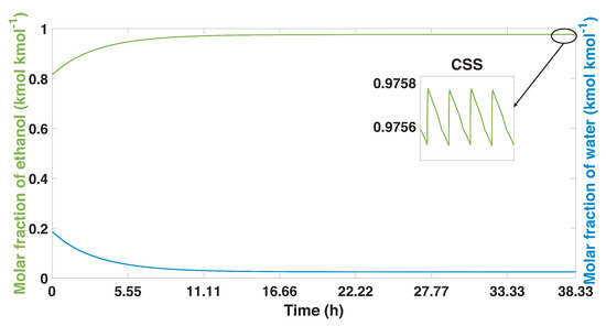
Figure 9.
Ethanol-water mixture purity profile, and the process from start-up to CSS in the study case 1.
The temperature profiles present different behaviors depending on the height. It can be seen that initially the temperature profiles are less unstable, showing variations in the first cycles; this behavior stabilizes as the CSS is reached (see Figure 10). In the bottom parts of the column (nodes 5 and 10), the highest values of temperature can be observed (465 K); in addition, these profiles are more stable compared to the profiles obtained in the top parts. At node 15, a less oscillating temperature profile can be observed than in the others. The highest part of the bed has the lowest temperature profiles (442 K).
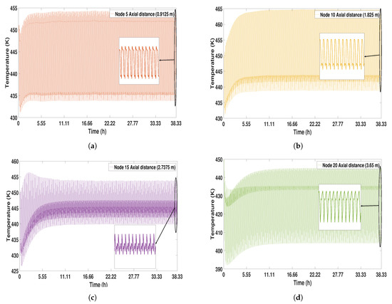
Figure 10.
Solid temperature profile from start-up to CSS (study case 1). (a) Node 5; (b) Node 10; (c) Node 15; (d) Node 20.
Study case 1 presents a large increase in productivity that the process achieves (Figure 11). In this case, better use of the column can be observed during the adsorption stage. The behavior of the profiles is similar to that observed in the experimental study case (Figure 5). At the beginning of the adsorption stage (0 s), the profiles are the lowest. As time passes, this profile tends to increase, reaching its maximum point after 345 s. In this case, there is little water adsorption between nodes 14 and 16 (2555 m and 2.92 m).
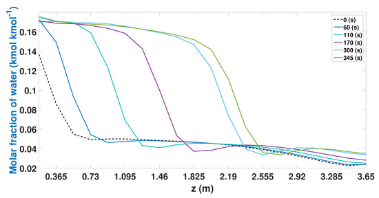
Figure 11.
Molar fraction of water during the adsorption stage from CSS (study case 1).
The regeneration profiles show how the column behaves once the adsorption part stage begins (Figure 12). During the initial part (0 s), the same profile that was obtained at the end of the adsorption stage is observed (Figure 11). As the regeneration stage is carried out, the column begins to recover a greater quantity of water, and the profiles reach their maximum point after 170 s. During the following seconds (180 to 345 s), the profiles begin to decrease, achieving the liberation of the active sites of the 3A zeolites.
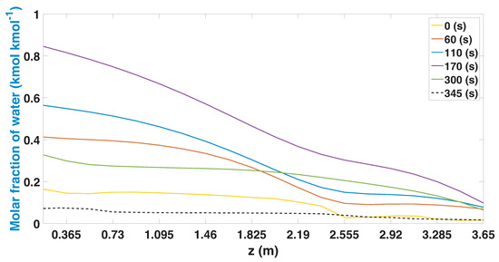
Figure 12.
Molar fraction of water during the regeneration stage from CSS (study case 1).
The highest heat profiles are found during the adsorption stage. These are found in the bottom and middle parts of the column (Figure 13). Temperature profiles decrease once the regeneration stage begins and have their lowest point in the top parts of the column. After 690 s, the temperature profiles are more stable, there is a greater amount of heat that is found in the middle parts of the bed, and they decrease as they approach the top part. The temperature profile of the mixture shows that the heat parts of the bed coincide with the parts where the greatest amount of water is adsorbed (Figure 11). Similarly, the top parts of the bed are where the least amount of heat is concentrated.
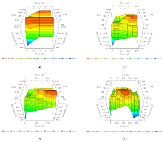
Figure 13.
Three-dimensional space graphics of the temperature profile along the bed, different times of a cycle; (a) 60 s, (b) 210 s, (c) 345 s, and (d) 690 s.
Figure 14 shows the behavior of the pressure profiles during one cycle in the CSS. Initially, in the adsorption stage, it is pressurized to a pressure of 395 kPa. This pressure is regularized throughout the column after 60 s. After 210 s, a slight pressure drop can be noticed. During the last seconds of adsorption, a pressure of 379 kPa is reached. The pressure profile remains stable until the adsorption stage is complete (345 s). At the end of this stage and the beginning of the regeneration stage, the column begins to depressurize, purge and repressurize to release the active sites of the 3A zeolites. This is done by lowering the pressure within the bed. The minimum peak observed during the purge step is 32.6 kPa.
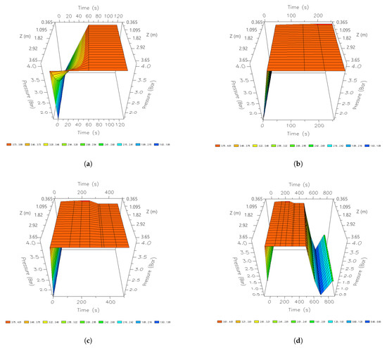
Figure 14.
Three-dimensional space graphics of the pressure profile along the bed, different times of a cycle; (a) 60 s; (b) 210 s; (c) 345 s; and (d) 690 s.
The report of cycles of study case 1 was carried out in cycles 29 (5 h), 100 (19 h), and 200 (38 h) (Table 6). In cycle 29 of the process, the highest levels of recovered water are observed, and the efficiency of energy is higher (85.48%) than in later cycles. The greater quantity of water is reflected in a greater quantity of material obtained (85.91%). After 100 cycles, the percentage of energy decreases (83.57%), which causes less water to be recovered in the final product. The amount of ethanol increases slightly; however, as more water is lost, production is lower than in previous cycles. When the CSS is reached after 200 cycles, the heat necessary to carry out all the steps of the cycle decreases; this causes a drop in the amount of water and ethanol in the final product; therefore, the percentage of production is also lower. When the results of the experimental study case obtained in Table 2 are compared, it can be noted that the water, in this case, is higher. These higher percentages of water are reflected in the greater efficiency of energy. Even recovering more water in the final production (8.92%), the purity is not very different from that obtained in the experimental case. This result is since the amount of ethanol is also higher in study case 1 (Table 6). The stream report shows these results in more detail.

Table 6.
Cycle report study case 1.
Table 7 and Table 8 show the purity percentages obtained as a final product, the amount of material, and the energy present in the different streams of the PSA process for study case 1. In cycle 29, the system recovers a quantity of water and ethanol compared to the experimental study case (Table 3). This presence of material makes the system require energy efficiency, in addition to achieving a decrease in purity. Likewise, it is possible to observe in cycle 29 that, after 345 s, the system continues to recover a greater amount of material; however, the heat profile has dropped so the column becomes more efficient to purify ethanol. The general cycles report (Table 8) shows that, once the CSS is reached, a higher percentage of ethanol and water is recovered, compared to the experimental study case. In turn, study case 1 requires a greater efficiency of energy to achieve similar levels of purity. Therefore, it can be deduced that Increasing the feed flow affects the amount of material that is recovered in production. A greater presence of ethanol and water requires higher profiles of heat, so energy efficiency is more required than in the experimental study case. A greater presence of water makes the column efficient in the adsorption stage (Figure 11). On the other hand, the waste generated by the PSA process is greater due to the increase in the purge flow.

Table 7.
Stream report study case 1.

Table 8.
General cyclic recovery report of study case 1.
The results obtained by the general cycles report of study case 1 show the amount of material recovered in each cycle, as well as the energy that was necessary to carry out the entire cycle. The changes made for a 3.65 m column obtained a percentage of ethanol purity similar to the experimental study case and increased the efficiency of the bed. The increase in the feed flow managed to improve the adsorption of the water in the bed; this effect is reflected in the amount of material that recovers. As there is a higher concentration of water in the process, naturally a greater efficiency of energy is required to carry out each cycle. Lowering the feed temperature ensures that these requirements (higher energy demand) do not adversely affect the purity obtained.
To perform study case 1, adjustments had to be made to the initial parameters. These adjustments are made to improve the use and preserve an optimal purity as obtained by the experimental study case [8]. Figure 11 shows an improvement in the use of the bed and uses around 75% of the bed to adsorb water. This improvement is reflected in stable temperature profiles. The purity achieved by the process is 99.20% wt of ethanol (Figure 9) after 200 cycles (38.33 h), reducing energy and equipment costs. The adjustments made comply with the requirement of maintaining ethanol purity that meets international standards to be used as fuel. Table 6, Table 7 and Table 8 show optimal results.
4.3. Study Case 2
Study case 1 showed that it is possible to use a smaller column and obtain results similar to those obtained in the case of the experimental study. An improvement in energy efficiency and a reduction in equipment costs were observed due to the reduction of the column. For study case 2, a column with the same dimensions as the experimental study case (7.3 m in height and 2.4 m in diameter) was proposed; this will allow for making the most of the bed. It is also expected to increase or preserve the purity of the product obtained (ethanol), complying with international standards to be used as an oxygenating additive or fuel. To obtain the aforementioned results, it is necessary to perform an analysis of the initial start-up conditions of the PSA process. Specifications for study case 2 are summarized in Table 9.

Table 9.
Specification of the required parameters for study case 2.
Figure 15 shows the purities obtained from water and ethanol in molar fraction using study case 2. In the first cycles of the process, small values of purity are obtained. The ethanol mole fraction begins to increase after 5 h. The CSS was reached after 58 h, reaching a purity of 99.01% wt of ethanol.
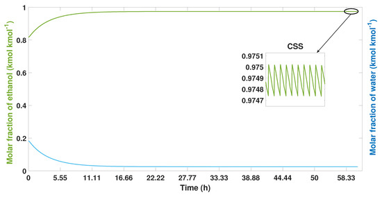
Figure 15.
Ethanol-water mixture purity profile, the process from start-up to CSS in study case 2.
In Figure 16, the temperature profiles are shown; these present a behavior with small oscillations compared to the experimental study case and 1 (see Figure 4 and Figure 10). In this case, the temperature decrements are smaller, having stable dynamics throughout the process. In the bottom parts of the bed, there is a temperature profile with a maximum value of 416 K, while, in the top part of the bed, there are temperatures with a value of 400 K.
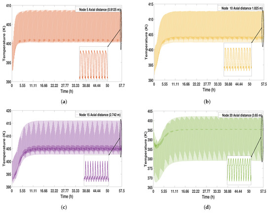
Figure 16.
Solid temperature profile from start-up to CSS. (a) Node 5; (b) Node 10; (c) Node 15; (d) Node 20.
The adsorption profiles in the study case 2 (Figure 17) show a great improvement in the use of the beds during the adsorption stage. In the initial times, there are adsorption profiles in the first three nodes of the bed. As the adsorption proceeds, most of the bed is used, reaching 10 knots (3.65 m) after 170 s. After 345 s, the adsorption profile reaches 16 nodes (5.84 m); this represents 85% of the total capacity of the bed to adsorb water.
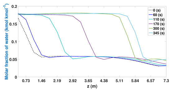
Figure 17.
Molar fraction of ethanol during the adsorption stage from CSS.
The regeneration stage (Figure 18) shows that the bed is capable of recovering a greater quantity of water compared to the other cases of study (Figure 6 and Figure 12), in turn releasing the greatest amount of water molecules adsorbed, to be used again in the adsorption stage. The 7.3 m high column can regenerate in most of its internal area, having a slight drop in the top parts of the bed. When the end of the regeneration stage (345 s) is reached, its shows that the profile is at the lowest point and it is free of water molecules.
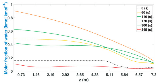
Figure 18.
Molar fraction of water during the regeneration stage from CSS.
During the first seconds of the adsorption step(60 s), the highest temperature profiles are observed in the intermediate parts of the bed. In this initial time, 405 K is reached (Figure 19). After 210 s, the temperature profiles are concentrated between nodes 6 and 10 (2.92 m and 3.65 m); at this point, the maximum profile is 410 K. The parts where high temperatures are concentrated are the areas where the greatest amount of water molecules is adsorbed. After the adsorption stage (345 s), the temperature profile becomes more stable. In the regeneration stage, the heat is concentrated to a greater extent at 5.475 m. In this stage, the lowest temperature profile (385 K) is obtained in the top part of the bed.
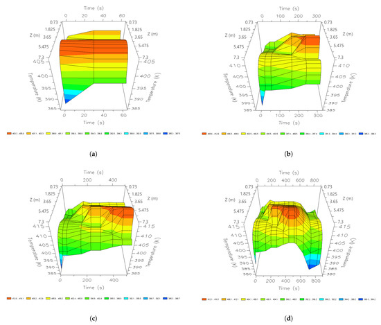
Figure 19.
Three-dimensional space graphics of the temperature profile along the bed, different times of a cycle; (a) 60 s; (b) 210 s; (c) 345 s; and (d) 690 s.
Figure 20 shows the increase in the pressure for the adsorption stage; for this case, the pressure of 385 kPa was used. In the first seconds of the adsorption step, the pressure increases rapidly until reaching 391 kPa in the entire interior area of the bed. This profile remains stable until the end of the adsorption stage, where a slight pressure drop occurs, and 385 kPa is reached. Once this stage is completed, the bed is fully regenerated by depressurizing and purging. When it occurs, the PSA process reaches a minimum of 32.6 kPa. Once the purge is complete, it is repressurized to start a new cycle.
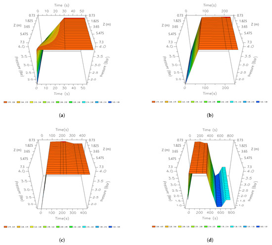
Figure 20.
Three-dimensional space graphics of the pressure profile along the bed, different times of a cycle; (a) 60 s; (b) 210 s; (c) 345 s; and (d) 690 s.
The cycle report was generated for cycles 30 (5.75 h), 150 (28.75 h), and 300 (57.5 h) (Table 10). In cycle 30, there is a greater presence of water in the product obtained, thus recovering a greater quantity of water than in subsequent cycles. In turn, greater energy efficiency is required to recover this amount of material. In cycle 150, there is a higher percentage of ethanol during the production stage. However, it should be noted that the amount of water recovered is lower and consequently the energy is lower compared to the initial cycles. Once the CSS was reached, 97.81% ethanol and 11.15% water were obtained in step 2; and, with this amount of material (82.07%), a purity of 99.01% wt of ethanol. To reach these values, the energy efficiency of 73.21% was required in the initial stage (step 1) of adsorption and 81.23% during step 2. This energy level is stable and will be the maximum efficiency that the process is able to achieve.

Table 10.
Cycle report study case 2.
Table 11 shows the stream report for study case 2. The results obtained show higher energy efficiency than in the other case studies (Table 3 and Table 7). In the first 30 cycles, in the product obtained, a molar fraction of water of 0.056 kmol kmol was recovered. For its part, the ethanol obtained is 0.943 kmol kmol. This percentage of ethanol, in the initial cycles of the process, is the lowest compared between the experimental case and case 1. After 150 cycles, the composition of ethanol and water is close to the result obtained when the CSS is reached. After 300 cycles, the material obtained in the product is the one with the highest percentage (compared to previous cycles). However, study case 2 obtained a value of 0.975 kmol kmol ethanol purity. This composition is lower than those obtained in the previous case studies: 0.988 kmol kmol (experimental case) and 0.980 kmol kmol (study case 1).

Table 11.
Stream report study case 2.
The cycle recovery report for study case 2 shows in a general way the results obtained in each cycle (Table 12). When the model is in a CSS (cycle 300), the beds recover 75.81% ethanol. This percentage is higher than that obtained in the experimental case (73.63), but it is lower than in study case 1 (77.41%). In addition, 8.77% of water is recovered in this case, while the experimental study case obtained 3.77% and 7.03% for the study case 1. This greater presence of water results in an improvement in the amount of zeolite that is used to adsorb water (Figure 17). However, this increase also generates a slight decrease in the final purity of the ethanol. As discussed in Table 11, the 7.3 m column designed for study case 2 has a higher percentage of recovered material (63.61%) compared to the experimental study case. Regarding energy efficiency, study case 2 has an energy share of 62.97%. This percentage corresponds to the amount of salvaged material and is greater than that of the experimental study case (60.91%) but less than that obtained in study case 1 (64.60%).

Table 12.
General cyclic report of study case 2.
The main approach to study case 2 was based on covering the deficiencies of the experimental study case (losses in the efficiency of the bed) and having higher productivity and purity of the ethanol obtained. Figure 15 shows that study case 2 was unable to increase the ethanol mole fraction. However, the percentage obtained (99.01% wt) meets international purity standards to be used as fuel. The results of Figure 17 show a drastic improvement in the use of the bed during the adsorption stage. It was possible to use 85% (during the CSS) of the column to produce the bioethanol. The deficiencies and efficiencies obtained in study case 2 are due to changes in the feeding parameters. With the aforementioned, it can be concluded that, with the decrease in temperature and pressure, It was possible to improve the efficiency of the model presented by [8], obtaining an insignificant decrease in the purity of the ethanol obtained.
5. General Conclusions
In this work, an analysis of the experimental study case presented by [8] was carried out. This case presents a deficiency in the amount of adsorption of water molecules in the bed since it uses only 30% of its maximum capacity (7.3 m in height and 2.4 in diameter). It produces ethanol at 99.50% wt, with an ethanol recovery of 73.33% using 60.09% energy.
For study case 1, it can be concluded that a smaller column (3.65 m in height and 2.4 in diameter) is capable of purifying ethanol at a molar fraction of 0.980 (99.20% wt of ethanol) in 200 cycles, and it uses only 75% of its maximum capacity to absorb water molecules, with an ethanol recovery of 77.41%. However, higher energy efficiency (63.96%) was required to achieve a percent purity greater than 99% wt of ethanol.
For case study 2, it is concluded that the use of adequate parameters in the start-up allows having an optimal process with beds that have the same dimensions as the experimental study case; these take advantage of 85% of their maximum capacity of adsorption, with an ethanol recovery of 75.81% and an energy efficiency of 62.97%. However, purity of 99.01% wt of ethanol was obtained in 300 cycles.
Both proposed study cases (1 and 2) comply with international purity standards to be used as an oxygenating additive or fuel; in both cases, it obtains purity of 99% wt of ethanol in fewer cycles compared to the experimental study case. They have a higher recovery of ethanol as a final production and the energy efficiency having a variation of the ±4% with respect to that obtained in the experimental study case.
As future work, a sensitivity analysis should be carried out on study case 1 in order to have an optimal process that improves energy efficiency and obtains a higher ethanol production. On the other hand, study case 2 opens up the possibility of designing and implementing control techniques that improve dynamics, optimize, and control the desired purity, rejecting disturbances.
Author Contributions
Formal analysis, G.O.T., J.Y.R.M. and J.C.R.C.; Investigation, A.R.L.N. and M.C.-R.; Methodology, J.D.L.C.-S., A.U.S.V., Y.A.M. and J.A.B.M.; Resources, A.F.P.V. and O.A.Z.D.; Software, J.Y.R.M.; Supervision, J.Y.R.M. All authors have read and agreed to the published version of the manuscript.
Funding
This research received no external funding.
Institutional Review Board Statement
Not applicable.
Informed Consent Statement
Not applicable.
Data Availability Statement
Not applicable.
Acknowledgments
We want to thank the Centro Universitario de los Valles of the University of Guadalajara for the access and use of the Laboratory of Sustainable Energy Processes, in which the PSA pilot plant, the bioreactor, and boilers are located.
Conflicts of Interest
The authors declare no conflict of interest.
Nomenclature
| Specific particle surface, (m m) | |
| Molar concentration of the component i, (kmol m) | |
| Specific heat capacity of adsorbent, (MJ kmol K) | |
| Molecular diffusivity i, (m s) | |
| Effective phase diffusivity adsorbed from component i, (m s) | |
| Interparticle voidage | |
| Intraparticle voidage | |
| F | Flowrate, (kmol h) |
| Axial dispersion coefficient of component i, (m s) | |
| Specific heat capacity of the adsorbed phase, (MJ kg K) | |
| H | Heat transfer coefficient of liquid / solid, ((J s) m K ) |
| h | Element size |
| i | Component index |
| J | Mass transfer rate, (kmol m(bed) s) |
| j | jth collocation point |
| K | Langmuir isotherm equilibrium constant ( Pa) |
| k | Iteration index |
| M | Molar weight, (kg mol) |
| s l | Element index |
| Isothermal parameters of component i | |
| MTC | Mass transfer coefficient solid, ( s) |
| k | Axial effective thermal conductivity (W m K) |
| OCFE2 | Orthogonal Collocation on Finite Elements |
| P | Pressure (Pa) |
| Q | Isosteric heat of adsorption (J mol) |
| Adsorbed amount of the component i, (kmol kg) | |
| Adsorbed equilibrium amount of component i, (kmol kg) | |
| R | Universal gas constant (J mol K) |
| r | Adsorbent particle radius (m) |
| t | Time (s) |
| Gas temperature, (K) | |
| Solid temperature, (K) | |
| T | Temperature, (K) |
| u | Position in element |
| Surface gas velocity, (m s) | |
| x | Position in catalyst |
| Molar fraction of the gas component i | |
| z | Coordinate of axial distance, (m) |
| Parameter in Glueckauf expression | |
| Particle shape factor | |
| Gas phase molar density |
Appendix A

Table A1.
Equations for the PSA process.
Table A1.
Equations for the PSA process.
| Total mass balance | |
| Pressure drop | |
| Energy balance | |
| LDF approximation | |
| Adsorption isotherm | |
| Initial and boundary conditions: | |
| Adsorption (Cycle step I): | Purgue (Cycle step III): |
| t = 0; | t = 0; |
| z = 0; | z = 0; |
| z = L; | z = L; |
| Depressurization (Cycle step II): | Repressurization (Cycle step IV): |
| t = 0; | t = 0; |
| z = 0; | z = 0; |
| z = L; | z = L; |
Appendix B. Orthogonal Collocation on Finite Elements
Modeling of any system can be done using techniques like process modeling, physical modeling, and statistical modeling. The technique of orthogonal collocation on finite elements (OCFE) is used for the study of flow dynamics and adsorption in fixed beds [35]. This method is a combination of two techniques viz: Finite Element Method (FEM) and Orthogonal Collocation Method (OCM). OCFE takes advantage of the accuracy offered by the orthogonal placement method and the ability of finite differences to locate a mesh of points where it is necessary to evaluate different changes [36] (see Figure A1).

Figure A1.
Subdivision of mesh points on the global domain.

Table A2.
Nodes equivalent to the distances in columns B1 and B2.
Table A2.
Nodes equivalent to the distances in columns B1 and B2.
| Nodes | Axial Distance | Unit |
|---|---|---|
| 1 | 0.0365 | m |
| 2 | 0.73 | m |
| 3 | 1.095 | m |
| 4 | 1.46 | m |
| 5 | 1.825 | m |
| 6 | 2.19 | m |
| 7 | 2.555 | m |
| 8 | 2.92 | m |
| 9 | 3.285 | m |
| 10 | 3.65 | m |
| 11 | 4.015 | m |
| 12 | 4.38 | m |
| 13 | 4.745 | m |
| 14 | 5.11 | m |
| 15 | 5.475 | m |
| 16 | 5.84 | m |
| 17 | 6.205 | m |
| 18 | 6.57 | m |
| 19 | 6.935 | m |
| 20 | 7.3 | m |
Appendix B.1. Description of the Method
The mathematical models describing the diffusion–dispersion process in a packed bed of fibers are based on axial dispersion and particle diffusion. These models are established in terms of transport equations using basic mass transfer operations like material balances and diffusion (Equation (1)). In orthogonal collocation on finite elements, the domain is divided into several small subdomains, called finite elements. For the problems discussed below, the domain of interest nodes is as shown in Figure A1 and Table A2. Within each element, the orthogonal placement procedure is applied, and the residue is evaluated at internal placement points. A new dimensionless variable u is defined for the element:
for and ; then, the variable u goes from 0 to 1 in element k. The interior placement points in each element are roots of the Legendre polynomial . Then, the orthogonal collocation method is applied on the new variable u. In this process, it is mandatory that the trial function and its first derivative should be continuous at the nodal points or at the boundaries of the elements [37]. The trial function is given by:
where:
where:
and
thus the ith finite element extends from:
to
with . The collocation points are chosen to be zeros of Orthogonal polynomials like Jacobi polynomials, Shifted Legendre’s polynomials, or Shifted Chebyshev’s Polynomials in the interval [0, 20]. The matrices B and A obtained are approximations to the second and the first derivative, respectively. The i points represent the interior placement points [38]. This system of equations creates a matrix system that can be described as:
where the vector C contains the unknown values of the composition at the interior placement points and at the final points of the elements. The matrix has a structure like the one seen in Figure A2. The diagonal blocks present an overlap between adjacent blocks. The elements of the blocks in matrix are stored in a three-dimensional array for calculations. The distribution of the vector F can be seen in the same Figure A2.
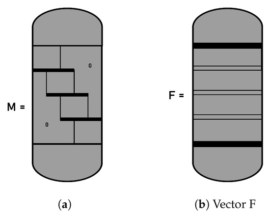
Figure A2.
Structure of the matrix for orthogonal placement on elements finite. (a) matrix ; (b) vector F.
References
- Sircar, S. Pressure Swing Adsorption Technology. In Adsorption: Science and Technology; Springer: Berlin/Heidelberg, Germany, 1989; pp. 285–321. [Google Scholar] [CrossRef]
- Makarem, M.A.; Mofarahi, M.; Jafarian, B.; Lee, C.H. Simulation and analysis of vacuum pressure swing adsorption using the differential quadrature method. Comput. Chem. Eng. 2019, 121, 483–496. [Google Scholar] [CrossRef]
- Oreggioni, G.; Friedrich, D.; Luberti, M.; Ahn, H.; Brandani, S. Development of an equilibrium theory solver applied to pressure swing adsorption cycles used in carbon capture processes. Comput. Chem. Eng. 2016, 94, 18–27. [Google Scholar] [CrossRef][Green Version]
- Martins, M.A.F.; Rodrigues, A.E.; Loureiro, J.M.; Ribeiro, A.M.; Nogueira, I.B.R. Artificial Intelligence-oriented economic nonlinear model predictive control applied to a pressure swing adsorption unit: Syngas purification as a case study. Sep. Purif. Technol. 2021, 276, 119333. [Google Scholar] [CrossRef]
- Todd, R.S.; He, J.; Webley, P.A.; Beh, C.; Wilson, S.; Lloyd, M.A. Fast Finite-Volume Method for PSA/VSA Cycle SimulationExperimental Validation. Ind. Eng. Chem. Res. 2001, 40, 3217–3224. [Google Scholar] [CrossRef]
- Cruz, P.; Santos, J.C.; Magalhães, F.D.; Mendes, A. Simulation of separation processes using finite volume method. Comput. Chem. Eng. 2005, 30, 83–98. [Google Scholar] [CrossRef]
- Jareteg, A.; Maggiolo, D.; Sasic, S.; Ström, H. Finite-volume method for industrial-scale temperature-swing adsorption simulations. Comput. Chem. Eng. 2020, 138, 106852. [Google Scholar] [CrossRef]
- Simo, M.; Brown, C.J.; Hlavacek, V. Simulation of pressure swing adsorption in fuel ethanol production process. Comput. Chem. Eng. 2008, 32, 1635–1649. [Google Scholar] [CrossRef]
- Abdel-Rahman, Z.A.; Mahmood, A.M.; Ali, A.J. Ethanol-Water Separation by Pressure Swing Adsorption (PSA). Iraqi J. Chem. Pet. Eng. 2014, 15, 1–17. [Google Scholar]
- Rajasree, R.; Moharir, A.S. Simulation based synthesis, design and optimization of pressure swing adsorption (PSA) processes. Comput. Chem. Eng. 2000, 24, 2493–2505. [Google Scholar] [CrossRef]
- Xu, M.; Wu, H.C.; Lin, Y.S.; Deng, S. Simulation and Optimization of Pressure Swing Adsorption Process for High-Temperature Air Separation by Perovskite Sorbents. Chem. Eng. J. 2018, 354, 62–74. [Google Scholar]
- Loy, Y.Y.; Lee, X.L.; Rangaiah, G.P. Bioethanol recovery and purification using extractive dividing-wall column and pressure swing adsorption: An economic comparison after heat integration and optimization. Sep. Purif. Technol. 2015, 149, 413–427. [Google Scholar] [CrossRef]
- Jiang, L.; Biegler, L.T.; Fox, V.G. Design and optimization of pressure swing adsorption systems with parallel implementation. Comput. Chem. Eng. 2005, 29, 393–399. [Google Scholar] [CrossRef]
- Sharma, P.K.; Wankat, P.C. Distillation-Adsorption Hybrid Processes to Separate Binary Liquid Mixtures with Homogeneous Azeotrope. Sep. Sci. Technol. 2013, 48, 1–14. [Google Scholar] [CrossRef]
- Karimi, S.; Karri, R.R.; Tavakkoli Yaraki, M.; Koduru, J.R. Processes and separation technologies for the production of fuel-grade bioethanol: A review. Environ. Chem. Lett. 2021, 19, 2873–2890. [Google Scholar] [CrossRef]
- Sant Anna, H.R.; Barreto, A.G.; Tavares, F.W.; de Souza, M.B. Machine learning model and optimization of a PSA unit for methane-nitrogen separation. Comput. Chem. Eng. 2017, 104, 377–391. [Google Scholar] [CrossRef]
- Subraveti, S.G.; Li, Z.; Prasad, V.; Rajendran, A. Machine Learning-Based Multiobjective Optimization of Pressure Swing Adsorption. Ind. Eng. Chem. Res. 2019, 58, 20412–20422. [Google Scholar] [CrossRef]
- Gibson, A.S.; Todd, R.S. Improved method to converge pressure equalization steps when simulating a cyclic adsorption process. Comput. Chem. Eng. 2019, 125, 185–203. [Google Scholar] [CrossRef]
- Beck, J.; Friedrich, D.; Brandani, S.; Fraga, E.S. Multi-objective optimisation using surrogate models for the design of VPSA systems. Comput. Chem. Eng. 2015, 82, 318–329. [Google Scholar] [CrossRef]
- Errico, M.; Madeddu, C.; Flemming Bindseil, M.; Dall Madsen, S.; Braekevelt, S.; Camilleri-Rumbau, M.S. Membrane assisted reactive distillation for bioethanol purification. Chem. Eng. Process.—Process Intensif. 2020, 157, 108110. [Google Scholar] [CrossRef]
- Rahimalimamaghani, A.; Pacheco Tanaka, D.A.; Llosa Tanco, M.A.; Neira D’Angelo, F.; Gallucci, F. New hydrophilic carbon molecular sieve membranes for bioethanol dehydration via pervaporation. Chem. Eng. J. 2022, 435, 134891. [Google Scholar] [CrossRef]
- Botshekan, M.; Moheb, A.; Vatankhah, F.; Karimi, K.; Shafiei, M. Energy saving alternatives for renewable ethanol production with the focus on separation/purification units: A techno-economic analysis. Energy 2022, 239, 122363. [Google Scholar] [CrossRef]
- Abdou Alio, M.; Marcati, A.; Pons, A.; Vial, C. Modeling and simulation of a sawdust mixture-based integrated biorefinery plant producing bioethanol. Bioresour. Technol. 2021, 325, 124650. [Google Scholar] [CrossRef] [PubMed]
- Li, K.; Gao, Y.; Zhang, S.; Liu, G. Study on the energy efficiency of bioethanol-based liquid hydrogen production process. Energy 2022, 238, 122032. [Google Scholar] [CrossRef]
- Guzmán-Martínez, C.E.; Maya-Yescas, R.; Castro-Montoya, A.J.; Nápoles Rivera, F. Dynamic simulation of control systems for bioethanol reactive dehydration: Conventional and intensified case studies. Chem. Eng. Process.—Process Intensif. 2021, 159, 108238. [Google Scholar] [CrossRef]
- Rumbo Morales, J.Y.; López López, G.; Alvarado Martínez, V.M.; Sorcia Vázquez, F.d.J.; Brizuela Mendoza, J.A.; Martínez García, M. Parametric study and control of a pressure swing adsorption process to separate the water–ethanol mixture under disturbances. Sep. Purif. Technol. 2020, 236, 116214. [Google Scholar] [CrossRef]
- Jiang, L.; Fox, V.G.; Biegler, L.T. Simulation and optimal design of multiple-bed pressure swing adsorption systems. AIChE J. 2004, 50, 2904–2917. [Google Scholar] [CrossRef]
- Khajuria, H.; Pistikopoulos, E.N. Dynamic modeling and explicit/multi-parametric MPC control of pressure swing adsorption systems. J. Process Control. 2011, 21, 151–163. [Google Scholar] [CrossRef]
- Sircar, S.; Hufton, J.R. Why does the linear driving force model for adsorption kinetics work? Adsorption 2000, 6, 137–147. [Google Scholar] [CrossRef]
- Ferraiolo, G.; del Borghi, M.; Solisio, C.; Gardi, R. Optimization Criteria for the Stabilization of Sewage Sludge and Biogas Production through Anaerobic Digestion: An Example of an Environmental Biotechnology Application. In ASTM Special Technical Publication; ASTM: West Conshohocken, PA, USA, 1984; pp. 260–277. [Google Scholar] [CrossRef]
- Simo, M.; Sivashanmugam, S.; Brown, C.J.; Hlavacek, V. Adsorption/desorption of water and ethanol on 3A zeolite in near-adiabatic fixed bed. Ind. Eng. Chem. Res. 2009, 48, 9247–9260. [Google Scholar] [CrossRef]
- Pruksathorn, P.; Vitidsant, T. Production of pure ethanol from azeotropic solution by pressure swing adsorption. Korean J. Chem. Eng. 2010, 26, 1106–1111. [Google Scholar] [CrossRef]
- Witte, N.D.; Denayer, J.F.M.; Assche, T.R.C.V. Effect of Adsorption Duration and Purge Flowrate on Pressure Swing Adsorption Performance. Ind. Eng. Chem. Res. 2021, 60, 13684–13691. [Google Scholar] [CrossRef]
- Matz, M.J.; Knaebel, K.S. Pressure swing adsorption: Effects of incomplete purge. AIChE J. 1988, 34, 1486–1492. [Google Scholar] [CrossRef]
- Ma, Z.; Guiochon, G. Application of orthogonal collocation on finite elements in the simulation of nonlinear chromatography. Comput. Chem. Eng. 1991, 15, 415–426. [Google Scholar] [CrossRef]
- Suwondc, E.; Pibouleau, L.; Domenech, S.; Riba, J.P. Simulation via Orthogonal Collocation on Finite Element of a Chromatographic Column with Nonlinear Isotherm. Chem. Eng. Commun. 1991, 102, 161–188. [Google Scholar] [CrossRef]
- Mittal, A.K.; Ganaie, I.A.; Kukreja, V.K.; Parumasur, N.; Singh, P. Solution of diffusion-dispersion models using a computationally efficient technique of orthogonal collocation on finite elements with cubic Hermite as basis. Comput. Chem. Eng. 2013, 58, 203–210. [Google Scholar] [CrossRef]
- Finlayson, B.A. Orthogonal collocation on finite elements-progress and potential. Math. Comput. Simul. 1980, 22, 11–17. [Google Scholar] [CrossRef]
Publisher’s Note: MDPI stays neutral with regard to jurisdictional claims in published maps and institutional affiliations. |
© 2022 by the authors. Licensee MDPI, Basel, Switzerland. This article is an open access article distributed under the terms and conditions of the Creative Commons Attribution (CC BY) license (https://creativecommons.org/licenses/by/4.0/).