Article

FeS2 Nanoparticles in S-Doped Carbon: Ageing Effects on Performance as a Supercapacitor Electrode

by
Sirine Zallouz
1,2,
Bénédicte Réty
1,2,3,
Jean-Marc Le Meins
1,2,
Mame Youssou Ndiaye
1,2,
Philippe Fioux
1,2 and
Camélia Matei Ghimbeu
1,2,3,*
1
CNRS, Institut de Science des Matériaux de Mulhouse (IS2M) UMR 7361, Université de Haute-Alsace, F-68100 Mulhouse, France
2
CNRS, Institut de Science des Matériaux de Mulhouse (IS2M) UMR 7361, Université de Strasbourg, F-67081 Strasbourg, France
3
Réseau sur le Stockage Electrochimique de l’Energie (RS2E), FR CNRS 3459, F-80039 Amiens, France
*
Author to whom correspondence should be addressed.
Submission received: 26 September 2023 / Revised: 2 November 2023 / Accepted: 7 November 2023 / Published: 17 November 2023

Abstract

:
Although transition metal sulfides have prodigious potential for use as electrode materials because of their low electronegativities, their large volume changes inhibit broad application. Moreover, there is only limited knowledge of the ageing processes of these materials at the nanoscale. Herein, nano-C/FeS2 materials were prepared via one-pot syntheses from green biodegradable carbon precursors, followed by activation and sulfidation. The increased activation/sulfidation time led to an increase in the size of the nanoparticles (7 to 17 nm) and their aggregation, as well as in an increase in the specific surface area. The materials were then used as electrodes in 2-electrode symmetric supercapacitors with 2 M KOH. The activation process resulted in improved capacitance (60 F g−1 at 0.1 A g−1) and rate capability (36%) depending on the composite porosity, conductivity, and size of the FeS2 particles. The ageing of the FeS2 nanoparticles was investigated under air, and a progressive transformation of the nano-FeS2 into hydrated iron hydroxy sulfate with a significant morphological modification was observed, resulting in drastic decreases in the capacitance (70%) and retention. In contrast, the ageing of nano-FeS2 during cycling led to the formation of a supplementary iron oxyhydroxide phase, which contributed to the enhanced capacitance (57%) and long-term cycling (132% up to 10,000 cycles) of the device.

Graphical Abstract

1. Introduction

Carbon has been extensively studied as an electrode material for supercapacitors. However, it has limitations due to the nonuniformly distributed pores that hamper the accessibility of ions to all active sites [1]. Other materials, such as transition metal oxides, are constantly proposed due to their high theoretical capacities. However, this family suffers from modest electronic conductivities [2]. Recently, other groups, such as transition metal sulfides (TMSs), have received attention. TMSs are generally semiconductors with electrical conductivity. The reason for this is that the sulfur atom has a lower electronegativity than oxygen, which facilitates electron transfer and therefore increases the capacitance [3]. Among the different TMS materials, pyrite FeS2 appears to be an interesting choice due to its natural abundance, low toxicity, and different active sites. It has been used in various energy storage systems, such as lithium-ion batteries [4], sodium-ion batteries [5], and supercapacitors [6]. However, it might exhibit large volume changes during cycling that can cause electrode degradation during long-term use [7].
The synthesis methodology has a substantial impact on the structure, morphology, and characteristics of the material. Therefore, the formation of particles with tuned properties and the syntheses of nanostructures are often seen as ways to obtain satisfactory electrochemical performance closer to the theoretical level [8]. For example, Venkateshalu et al. [9] synthesized octahedral-shaped FeS2 particles to sizes of ~200 nm via a solvothermal method. The as-prepared material was tested in a three-electrode system in both 3.5 M KOH and 1 M Na2SO4 with low mass loadings on the working electrode of 1.9 mg and 1.7 mg, respectively. The material exhibited capacitances of 269 F g−1 at 1 A g−1 and 120 F g−1 in alkaline and neutral electrolytes, respectively [9].
To increase the electrochemical performance, the mixing of carbon materials with TMS is an encouraging strategy because it enhances the electrical conductivity of the TMS [10]. In the literature, the most commonly used synthesis method is preparation of the carbon material, generally graphene oxide (GO) or reduced graphene oxide (rGO), followed by incorporation of the metal sulfide precursors (iron salts for Fe and different sources for sulfur, e.g., sodium thiosulfate [7], ammonium thiocyanate [11], cysteine [12], sulfur powder [5], or sulfidation under H2S [13]) to synthesize the carbon/FeS2 composite used for electrodes in energy storage devices [14]. This synthesis route is acceptable but requires multiple steps, which increases the overall cost. Pei et al. synthesized flower-like FeS2 on a graphene aerogel using a two-step self-assembly method. After preparing GO using the Hummer method, iron sulfate (FeSO4) and sodium thiosulfate (Na2S2O3) were added to the GO solution, and graphene aerogel/FeS2 composites were prepared via hydrothermal synthesis at 180 °C for 16 h. The FeS2 particles had sizes ranging from 250 nm to 2 µm, and most of them were severely agglomerated. The material exhibited a capacitance of 313.6 F g−1 at 0.5 A g−1 in a three-electrode cell containing 6 M KOH [7]. In another study, FeS2/carbon microspheres were synthesized by first preparing Fe3O4/carbon microspheres that were later mixed with sulfur powder and annealed at 500 °C under argon for 5 h to obtain the FeS2/carbon microspheres. The material showed a capacitance of 278 F g−1 at 1 A g−1 with 1 M KOH in a three-electrode system [13].
In fact, it has been shown before that the confinement of particles in carbon inhibits particle growth, thus maintaining small particles with limited aggregation throughout thermal treatments or electrochemical cycling [15,16]. Furthermore, the carbon matrix is also a useful scaffold to improve electronic conductivity and porosity [17]. In a recent report, graphene-wrapped FeS2-FeSe2 core-shell spheres with sizes of ~1 µm were synthesized and used as the negative electrode in an asymmetric supercapacitor. The device exhibited a capacitance of 352.3 F g−1 at 1 A g−1. This was attributed to the protection of the particles through encapsulation in carbon, which reduced the dissolution of the metal ions during cycling and thus preserved the cycling lifetime of the device [18].
This state-of-the-art overview shows that synthesized FeS2 has large particle sizes, and in some reports, the particle sizes are not mentioned at all. No systematic study has been conducted on nanoparticles with sizes smaller than 20 nm confined in carbon. Consequently, new synthesis approaches are required to ensure that the small particles in the carbon matrix are distributed homogeneously [17]. Moreover, despite its high potential as an electrode material, there are fewer reports on FeS2 than there are on other TMSs and TMOs; therefore, it should be thoroughly investigated. Furthermore, it should also be mentioned that most previous reports [12,19] on TMSs determined the capacitances in half-cell or three-electrode cell configurations, which measured the electrochemical performance of a single electrode in a specific electrolyte. This configuration gives capacitance readings that are higher than those of two-electrode devices and is not representative of a real two-electrode working system. The use of a symmetric two-electrode configuration for transition metal sulfides in general, and FeS2 in particular, has been poorly reported until now, as noted in a recent review article [10]. To our knowledge, the only example was provided in a very recent report of a symmetric solid supercapacitor composed of FeS2/carbon nanofibers and PVA-KOH gel electrolyte, which exhibited a specific capacitance of 203.4 F g−1 at 1 A g−1 [5].
Another important aspect that needs to be mentioned is the ageing of the nanoparticles. To our knowledge, pyrite nanoparticles have not been reported, although pyrite in the nanosize is more prone to oxidation than their oxide counterparts [20]. This ageing effect was not studied with supercapacitor electrodes, and there is a lack of knowledge on the structural and morphological evolution during cycling. The ageing of carbonaceous materials during cycling led to modifications in the porosity, structure, and surface chemistry, in particular for the positive electrode [21]. This caused a decrease in the capacitance of the device. These aspects of ageing are rarely studied, and the new interest in these issues shows their importance. Investigating the ageing processes of nanoparticle electrodes could prevent later problems that may occur during the life of a supercapacitor.
It is clear from the above literature that there is a lack of studies on FeS2 at the nanoscale. Moreover, the electrochemical tests are limited to 3-electrode cells, although 2-electrode system tests should be reported for better comparison with different material families. Nevertheless, ageing phenomena are crucial for electrochemical behaviour and device life, therefore, their understanding is of prime importance, and has not been investigated before. All of these problems mentioned above motivate this work to provide a comprehensive systematic study on FeS2 nanoparticles as supercapacitor electrodes.
Herein, a novel synthesis route of carbon-containing nanoparticles of FeS2 starting from green biosourced precursors, followed by pyrolysis, sulfidation, and activation is reported. Cysteine containing sulfur and nitrogen is used for a double purpose, i.e., as a sulfur source for FeS2 formation and to dope carbon with these elements. The optimization of the sulfidation temperature and activation time were investigated to obtain materials with tuned particle size and porosity. The capacitance, rate capability, and cycling life could be improved depending on the material properties (particle size, porosity, and conductivity). The ageing of the materials was studied in air and during electrochemical cycling and evidenced progressive modifications in the morphology and structure. Ageing in air is detrimental to performance, while ageing in an electrolyte promotes redox reactions and improves performance. The results described herein provide a comprehensive understanding of the phenomena occurring at the interfaces of the electrode with both the air and the electrolyte, which have never been addressed to the best of our knowledge.

2. Materials and Methods

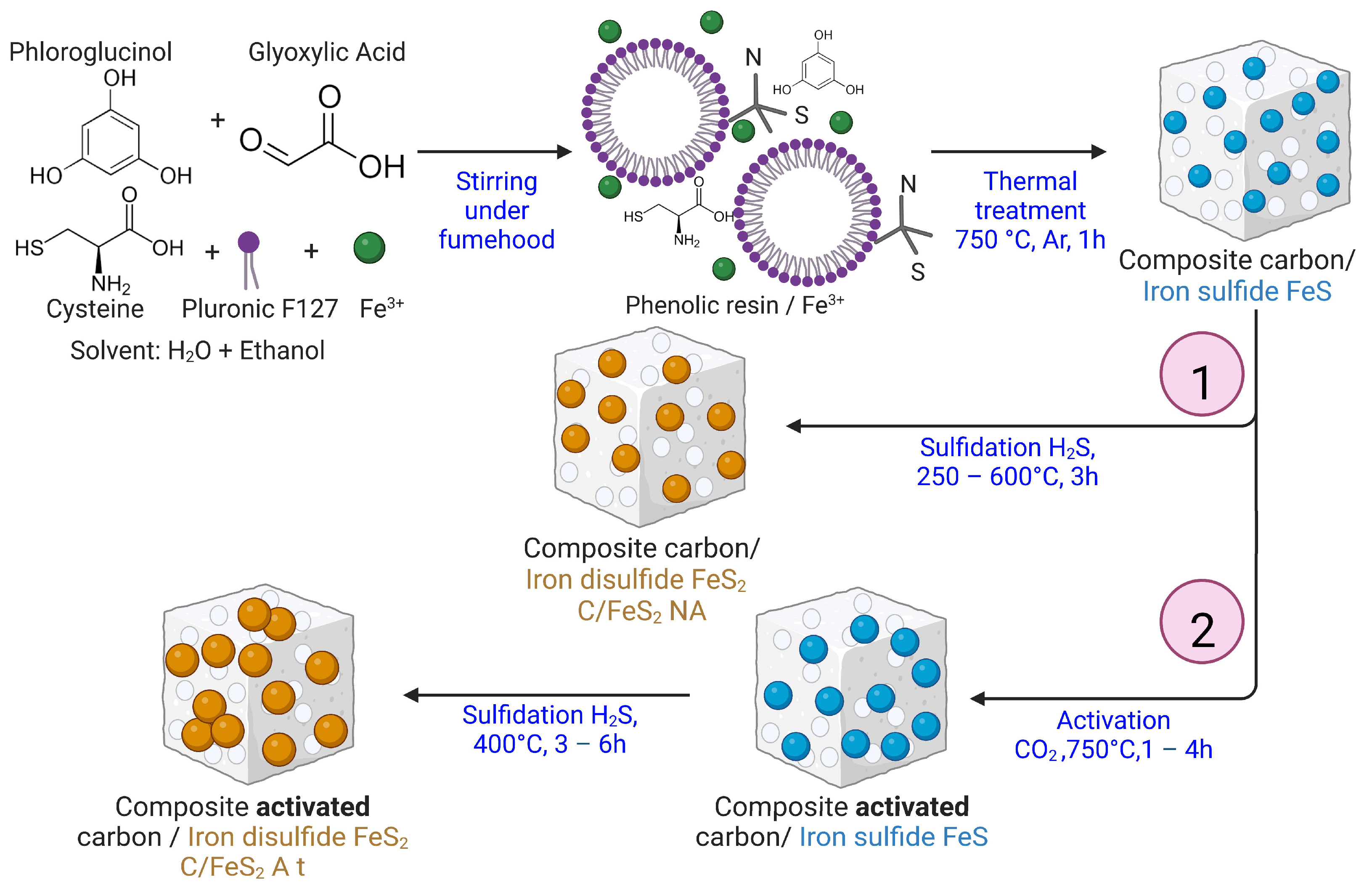
2.1. Synthesis of C/FeS2 Composites

The C/FeS2 composites were synthesized via a new one-pot synthetic method, as shown in Figure 1. The green carbon precursors of phloroglucinol (1.23 g), glyoxylic acid (1.2 g), and L-cysteine (1.76 g) were used as the sulfur precursors and Pluronic F127 (1.21 g) was used as the pore/structure-directing agent, and all were mixed together in 60 mL of a solvent mixture (with a water:ethanol volume ratio of 75:25) in a Teflon beaker. The reaction mixture was stirred until all precursors were completely dissolved (approximately 20 min). Then, 4.88 g of iron(III) nitrate nonahydrate (Fe(NO3)3·9H2O) was added to the reaction mixture as the iron source. The solution was kept in the fume hood and continuously stirred until the solvent was completely evaporated (generally 48 h). The dry polymer/iron salt mixture was then placed in an alumina tube and pyrolyzed under flowing argon (8 L h−1) at 750 °C for 1 h with a heating rate of 2 °C min−1. The products were kept in the furnace until the temperature dropped below 45 °C.
This synthesis afforded the carbon/iron sulfide (FeS) composites. Two approaches have been considered to convert the FeS into FeS2. In the first route (1), the as-prepared C/FeS composites were directly subjected to sulfidation at different temperatures (250–600 °C) under a mixture of H2S (2 L h−1) and argon (8 L h−1) for 3 h. The obtained composite was denoted as C/FeS2 NA (NA means nonactivated).
In the second route (2), physical activation was performed before the sulfidation step. CO2 was used in an activation step carried out at 750 °C for different times (1–4 h), which was then followed by the same sulfidation step used in route 1. The sulfidation temperature was 400 °C, and the time of exposure to H2S was 3 h for most materials but was adjusted to 6 h for the material activated for 4 h. The resulting composites were noted as C/FeS2 A t with t being the time of activation in hours (h). It should be highlighted that during activation under CO2 and sulfidation under H2S, the heating and cooling steps were carried out under an inert atmosphere. The specific gases were introduced only at the indicated temperatures.
For comparison purposes, unsupported FeS2 (named nano-FeS2) was prepared from commercially nanosized Fe2O3 (Sigma Aldrich, Saint-Louis, MO, USA) according to the procedure used for the C/FeS2 composites (400 °C for 3 h under a mixture of H2S/Ar).

2.2. Physicochemical Characterisation

The nanocomposites were characterised via powder X-ray diffraction (XRD) using a Bruker, D8 ADVANCE A25 instrument (Bruker, Billerica, MA, USA) in θ-θ configuration. The diffractometer is equipped with a LynxEye XE-T high-resolution energy dispersive 1-D detector and operates at <380 eV with Cu Kα1,2. Data were collected over the 2θ range of 10 to 90°.
A semiquantitative study of composite ageing was performed for a period of ~4 months, and diffractograms were recorded each week. The as-collected diffraction data allowed us to evaluate the weight percentage (concentration) of a given phase with a semiquantitative analysis using peak heights and a reference intensity ratio (RIR). The semiquantitative (SQ) analysis was conducted as described in the Supporting Materials, SI. The use of a Crystallography Data Base (COD) is preferred in this study and the reasons are explained in the SI part.
Thermogravimetric analyses were carried out using a Mettler Toledo instrument under a gas flow of 100 mL min−1 and by heating in an alumina (Al2O3) crucible from 25 to 900 °C at a rate of 2 °C min−1. The purpose of this study was to estimate the amounts of FeS2 in the composites, as described in the SI.
The surface morphologies and microstructures of the samples were investigated using transmission electron microscopy (TEM) and scanning transmission electron microscopy (STEM) using an ARM-200F instrument (Jeol, Tokyo, Japan). ImageJ [22] software was used to treat the STEM images and to determine the particle size distributions by counting ~500 particles from several images obtained at different magnifications. The chemical composition, nature, and the amounts of metal and functional groups were determined using an XPS SES-2002 spectrometer (Scienta Omicron, Uppsala, Sweden) equipped with a monochromatic X-ray source (Al Kα = 1486.6 eV) and a VG Scienta XM780 monochromator.
The textural properties were determined using a ASAP 2020 porosimetry system (Micromeritics Instrument Corporation, Norcross, GA, USA) with N2 as the adsorbate at 77 K. Prior to the adsorption measurements, the samples (~100 mg) were placed into a glass tube and outgassed under a vacuum at 90 °C for 12 h. Furthermore, a second outgassing was performed at 90 °C under a vacuum for 2 h. The specific surface areas (SBET), total pore volumes (VT), micropore volumes (Vmicro), and mesopore volumes (Vmeso) were determined as described elsewhere [15]. The pore size distributions were determined from the adsorption isotherms and the 2D-NLDFT (two-dimensional nonlocal density functional theory) heterogeneous surface for carbon materials explored using SAIEUS software (Version 3.2).

2.3. Electrochemical Studies

The electrodes were prepared by mixing an 80 wt% of the active material (C/FeS2-NA and C/FeS2-A t and nano-FeS2), with a 10 wt% of a conductive additive (ENSACO 350G, from IMERYS, Paris, France) and a 10 wt% of a binder, which was polytetrafluoroethylene PTFE (60% wt dispersion in water), dissolved in ethanol. The mixture was blended manually in an agate mortar until the solvent evaporated and a homogeneous paste was formed. The manual grinding enables a better homogeneity of the electrode. The paste was then spread between two plastic foil sheets to achieve a paste thickness of 200–250 μm. Then, self-standing electrodes with 10 mm diameters and 10–17 mg loadings were cut using a round punch and then dried under a vacuum at 120 °C for 12 h. The materials were tested in 2-electrode Swagelok cells with a symmetric configuration. All measurements were carried out using a multichannel VSP300 Potentiostat (Biologic, France). Cyclic voltammetry (CV), galvanostatic charge with potential limitation (GCPL), and electrochemical impedance spectroscopy (EIS) were conducted using a 2-electrode cell assembly containing 2 M KOH as the electrolyte, qualitative filter paper as the separator, and stainless-steel current collectors. The current collectors were covered with a layer of conductive glue (Loctite ElectroDag PF 407C) to ensure better contact and conductivity with the electrode. To characterise the materials further and observe the redox peaks, a 3-electrode cell was built. In this case, Hg/HgO was used as the reference electrode, a Pt mesh was used as the counter electrode, and the same electrolyte and current collector were used. The specific capacitance was calculated from the GCPL of the 2-electrode measurement by using the mass of the active material in one electrode, according to Equation (1) [23]:
C e l e c t r o d e = 2 × I × S d i s U m a x 2  
where Celectrode is the specific capacitance of the active material in the working electrode in F g−1, I is the applied current density of the active material in the working electrode in A g−1 reported to the mass of active material in the electrode, Sdis is the area under the discharge curve in V·s, and Umax is the electrochemical window in V. The energy density E and power density P were determined following these equations [21]:
E = 1 2   C e l e c t r o d e U 2  
P = E t d i s  
where E is the energy density in W h kg−1, tdis is the discharge time in s, and P is the power density in W kg−1.
Cycled electrodes were washed in 50 mL of distilled water and then dried at 80 °C for 8 h before postmortem characterisation with XRD and TEM.

3. Results

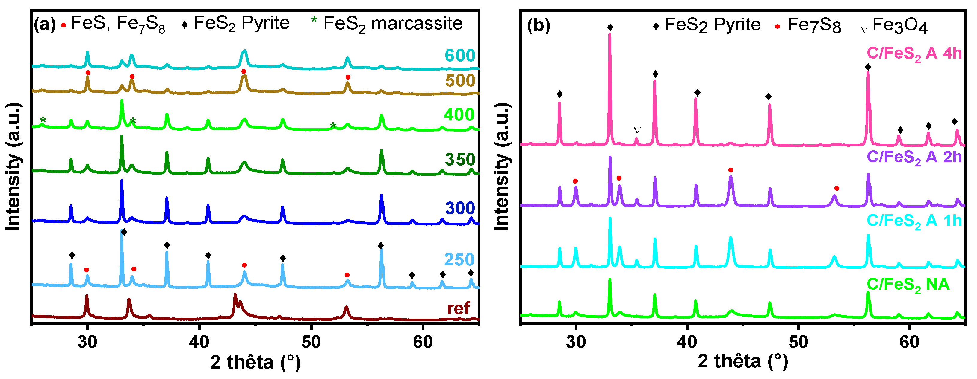
3.1. Carbon/FeS2 Formation

The first step of the synthesis involved a mixture of the carbon precursors of phloroglucinol-glyoxylic acid and cysteine (the source of S), the Pluronic F127 surfactant, and iron nitrate in a water/ethanol mixture. A phenolic resin based on the phloroglucinol-glyoxylic acid-cysteine was formed through polymerization [24]. The abundant –OH and –COOH groups present in the phenolic resin allowed self-assembly with the ethylene oxide units of surfactant micelles through H-bonding [25]. Depending on the interactions involved, the iron nitrate can be located either in the vicinity of the micelles and/or within the phenolic resin structure [26]. The continuous mixing of the precursors until the solvent evaporated ensured the complete integration of the iron precursor into the polymer matrix. The obtained nanoassembly was pyrolyzed under Ar, leading to the decomposition of the phenolic resin to form the carbon network. Simultaneously, the surfactant micelles resulted in the creation of mesopores through a soft-template synthesis method [25]. The thermal degradation of cysteine had a double function in the synthesis: first, it ensured the doping of the carbon with S and N, and second, it provided sulfur as a source for FeS2 formation. The iron(III) nitrate decomposed with increasing temperature, and it formed Fe2O3 at approximately 180 °C [27]. Then, the temperature was increased (up to 750 °C), and the iron oxide present in the material was sulfidated by the sulfur from the cysteine through the following reaction:
2   F e 2 O 3 + 4   S   s 4   F e S + 3   O 2   g  
During this step, the carbon reduced the iron oxide, thus simplifying the process of FeS formation, as reported for the WS2 formation [28].
XRD data for the material was obtained after the pyrolysis step, denoted C/FeS ref, as shown in Figure 2. Large distinguishable reflections were observed, and identification of the phases by XRD using COD indicated a mixture of different FeS phases with two hexagonal crystallographic forms according to COD 1504400 (centrosymmetric NiAs-type structure, with space Group P63/mmc) and COD 9004036 for Troilite-type FeS [29], which was not centrosymmetric (space group P 6 ¯ 2c). Fe7S8 pyrrhotite 4C, COD 2104739, which contains a superstructure related to the NiAs-type, was required to describe the distribution of iron vacancies within the unit cell [30].
In a second step, different thermal treatments were performed with a mixture of H2S/Ar to determine the optimal temperature for the formation of pyrite. Figure 2a,b shows the XRD data obtained at 250 to 600 °C for the different materials. For comparison purposes, the C/FeS ref composite pyrolyzed at 750 °C (without H2S treatment) is provided in the same figure.
After sulfidation at the lowest temperature (250 °C), a significant fraction of FeS had already been transformed to FeS2 via Equation (5) [31]:
2   F e 2 O 3 + 4   S   s 4   F e S + 3   O 2   g  
This is shown through the decreased intensities of the FeS reflections and the appearance of several additional intense peaks (2θ = 28.5, 33.0, 37.0, 40.7, 47.4, and 56.2°). These newly formed peaks were indexed as two coexisting polymorphs of FeS2: pyrite (COD 9000594) with cubic symmetry (Pa 3 ¯ ) and marcasite (COD 9013067), which is orthorhombic (Pnnm). Marcasite is metastable with respect to pyrite from 270 to 430 °C, and above 430 °C, marcasite undergoes an irreversible exothermic transformation compared to pyrite [32]. In contrast, pyrite is stable at higher temperatures and is thought to be the predominant phase.
Therefore, increasing the reaction temperature to 400 °C increased the proportion of the pyrite FeS2 phase and eliminated the FeS phase. The other peaks associated with the undesirable phase (FeS2 marcasite, FeS troilite, and Fe7S8 pyrrhotite 4C) also weakened. At this temperature, FeS2 pyrite was the predominant phase in the material, and only small peaks for the FeS2 marcasite were detected. Above 500 °C, decomposition of the pyrite with the reformation of FeS was observed. Therefore, 400 °C was chosen as the optimal sulfidation temperature for the rest of the composites.
Physical activation is known to increase the porosities of carbon materials, which is important for supercapacitor performance [33]. However, most of the studies were performed with carbon materials, and composites were rarely reported, as was the case for the carbon/FeS composites. Therefore, the C/FeS material was activated under CO2 for 1 h, 2 h, and 4 h prior to the sulfidation treatment. During this process, some of the carbon was burnt off due to the exposure to an oxidizing environment (CO2).
Furthermore, it was shown that at temperatures between 750 and 800 °C, the oxidation reaction was slow [33]; therefore, 750 °C was chosen for this study. The activation process took place according to the reverse Boudouard equation [34]:
C   ( s ) + C O 2   ( g ) 2   C O   ( g )  
The resulting activated materials were sulfided at 400 °C to obtain the C/FeS2 composites. Then, the composites were characterised in-depth using several techniques. The crystallographic structures of the activated C/FeS2 materials were identified by XRD and compared to that of the nonactivated material (C/FeS2 NA) (Figure 2b). Overall, pyrite FeS2 was the predominant phase in the three activated materials, as it was in the nonactivated material. A tendency toward narrower peaks was observed with increasing activation time, indicating an increase in the size of the coherent diffraction domain during the thermal treatments (activation and sulfidation).
Small traces of Fe7S8 were still present with more or less distinguishable peaks observed for all materials. Small amounts of iron oxide, Fe3O4 (COD 1513304), were also detected in all of the activated C/FeS2 samples due to the activation with CO2 (Figure S1, SI). The amounts increased with increasing activation times and reached the highest level at 4 h of activation, which is why the reductions with H2S/Ar required 6 h instead of 3 h for this material. To conclude, after 4 h of activation followed by 6 h of sulfidation, the diffractogram indicated the highest pyrite FeS2 content among all materials.
The STEM images for the C/FeS2 composites are provided in Figure 3. The C/FeS2 materials presented an average size of 7.0 nm for C/FeS2 NA, which increased to 12.5 nm for C/FeS2 A 1 h, 14.5 nm for C/FeS2 A 2 h, and 17.1 nm for C/FeS2 A 4 h. Therefore, as the activation time was increased, the particles became larger and tended to coalesce, as shown in Figure S2, SI.
The average sizes of the particles were very small and did not exceed 20 nm, which was smaller than those reported in the literature [35,36]. This was particularly interesting, as it offered the possibility to evaluate the electrochemical activity of FeS2 on the nanoscale. Moreover, the particles were well-dispersed in the carbon matrix after short activation times. This was due to the one-pot synthesis that ensured the efficient confinement of the particles within the carbon walls [37]. However, as activation proceeded longer, the particles became more aggregated. This behaviour was previously described as the Oswald ripening mechanism [38] that occurs spontaneously and is explained thermodynamically by the fact that large particles are energetically favoured because larger particles are more stable than smaller particles. This was confirmed through the activation, which created the pores that provided more space for the particles to aggregate. In some cases, very large particles with different sizes varying up to 400 nm (Figure S3, SI) were observed. This was particularly true for C/FeS2 A 4 h, as the distribution showed particles with sizes of ~40–60 nm.
The amounts of FeS2 in the composites were estimated from TGA data (Figure S4, SI, and Table 1). Details of the calculation method and the equation used are provided in the SI.
Previous works have used the same technique to determine the FeS2 amount in carbon/FeS2 composites [7,36]. The FeS2 percentages in the composites were ~15, 18, 22, and 23% for C/FeS2 NA, C/FeS2 A 1 h, C/FeS2 A 2 h, and C/FeS2 A 4 h, respectively. The activation process led to slight increases in the FeS2 percentages in the composites. The XRD data for the resulting powder confirmed the formation of the Fe2O3 phase, as shown in Figure S5, SI. It should be mentioned that the presence of some traces of Fe7S8 and Fe3O4 in the different composites contributes to the resulting FeS2 value, therefore, it is only an estimation of the real value.
The textural properties impact the electrochemical performance of a composite. Therefore, nitrogen adsorption/desorption experiments were performed with the composites, and Figure 4a,b presents the corresponding isotherms and pore size distributions. The isotherms (Figure 4a) presented mixed shapes between those of type I and type IV isotherms [39], with H4 hysteresis loops for C/FeS2 NA and C/FeS2 A 1 h, and H3 hysteresis loops for C/FeS2 A 2 h and C/FeS2 A 4 h [40]. This indicated the presence of both micro- and mesopores. During the activation process, the volume of micropores increased until 2 h of activation and then decreased after 4 h of activation, which was observed at the relative pressures of P/P0 < 0.1. This resulted in specific surface areas (SSAs) of 161, 185, 296, and 214 m2 g−1 for C/FeS2 NA, C/FeS2 A 1 h, C/FeS2 A 2 h, and C/FeS2 A 4 h, respectively, as seen in Table 1. The decrease in SSA after 4 h of activation was caused by several factors: (i) the FeS2 particles were larger and may have blocked access to some pores, (ii) the amount of metal particles in the material increased slightly with increasing activation times while the carbon amount decreased, and (iii) the long activation times may have caused pore enlargement, which does not account for the micropore contributions to the SSA.
Mesopores were also present, but with smaller volumes. Two types of mesopores were observed for all of the materials: (i) intrinsic mesopores with average sizes of ~4 nm (inset of Figure 4b) and (ii) intergrain mesopores measuring ~23 nm, which probably arose from the spaces between the FeS2 nanoparticles that grew outside of the carbon for 2 h and 4 h. The presence of intergrain porosity was sustained by the shape of the isotherm, which showed an increase in the adsorption volume at high P/P0 (>0.8).
The presence of micropores and mesopores is important for electrochemical evaluations because it enables the efficient flow of the electrolyte ions during charge and discharge. The pore size distribution determined by 2D-NLDFT indicated the presence of many micropores with sizes of ~0.7 nm in all materials. These micropore sizes are very interesting for a supercapacitor electrode material, since a match of micropore size with the electrolyte ion size leads to the enhancement of the capacitance, as has been shown elsewhere [41].
XPS is a surface analysis technique, and it was used to determine the chemical compositions, chemical bonds, and functional groups in the composites (C/FeS2 NA, C/FeS2 A 1 h, and C/FeS2 A 4 h). The results are gathered in Figure 4c,d and Figure S6. Based on the XPS survey spectra, the C 1s, O 2p, S 2p, Fe 2p, and N 1s amounts were determined (Figure 4c).
The carbon functional groups exhibited the highest proportions in all of the composites; (58.36 at.%) for C/FeS2 NA, (50.63 at.%) for C/FeS2 A 1 h, and (69.36 at.%) for C/FeS2 A 4 h. Then, oxygen showed rather similar values (27.48 at.%) for C/FeS2 NA and (32.93 at.%) for C/FeS2 A 1 h, while for C/FeS2 A 4 h (11.24 at.%), the quantity decreased significantly. This might be due to the longer activation time (6 h vs. 3 h), which caused the removal of more oxygen groups. The reduced oxygen groups are in favor of S groups, which increased continuously with the activation time from 9.74 to 15.47 at.%.
The amount of nitrogen was low (2.76 at.% maximum) as a result of cysteine decomposition. There was a slight decrease in the N 1s peak intensities (Figure 4c), which was caused by the removal of NOx groups at longer activation times [42]. In the literature, S-doped carbon [43] and N-doped carbon [44] showed superior electrochemical activities in supercapacitors. This doping improved the pseudocapacitance and electronic conductivity, and hence the rate capability and stability during long-term cycling. With increased activation times, the Fe 2p3/2 peak for the extreme surface also increased (Figure 4c).
Deconvolution of the high-resolution C 1s spectrum showed that the main contribution came from sp2-hybridized C, and several other smaller contributions came from oxygen-based functional groups (C-C=O, C-OR, C=O, and COOR) and C-S bonds (Figure 4d). In general, oxygen groups present on the carbon surface were reported to improve the wettability, increase electrolyte diffusion, and contribute to some pseudocapacitive reactions, hence improving the capacitance [45]. However, large amounts might diminish the electronic conductivity.
Deconvoluted high-resolution N 1s and S 2p spectra are presented in Figure S6a, SI. For nitrogen, the observed groups included pyridine (C=N) at 398.15 eV, pyrrolic groups (C-NHx) at 400.29 eV, and quaternary groups (C-N+) at 401.51 eV. The proportion of pyrrolic groups increased slightly with increasing activation time, and reduced the proportion of quaternary groups due to the removal of more carbon atoms, and hence the formation of C=N double bonds. Thus, during pyrolysis, nitrogen was incorporated into the carbon structure. This approach was previously used to dope carbon with other nitrogen sources [46].
In Figure S6b, SI, the high-resolution sulfur spectra showed differences for the different materials. For C/FeS2 NA and C/FeS2 A 1 h, the spectra contained peaks at 168–170 eV attributed to oxidized sulfur (sulfates and sulfoxides) [47]. Interestingly, the proportions of these compounds decreased significantly for C/FeS2 4 h as FeS2 was formed, probably because the longer treatment with H2S (6 h) caused the reduction of oxygen and sulfur. The larger particle sizes of this material (~17 nm) inhibited oxidation compared to that of the other materials containing smaller particles (7 to 12.5 nm).
For the Fe comparison, the XPS spectra of Fe 2p3/2 are provided in Figure S7a, SI. As can be observed, the material activated for the longest duration (C/FeS2 4 h) shows the highest peak of FeS2 contribution (707 eV), attesting to the presence of the richest pyrite phase in this material. Iron oxides with a high oxidation state (Fe2+,3+ and Fe3+) coming from Fe2O3 or Fe3O4 are less significant due to their reduction into Fe2+ (FeO). These results are in agreement with the other characterisation techniques.

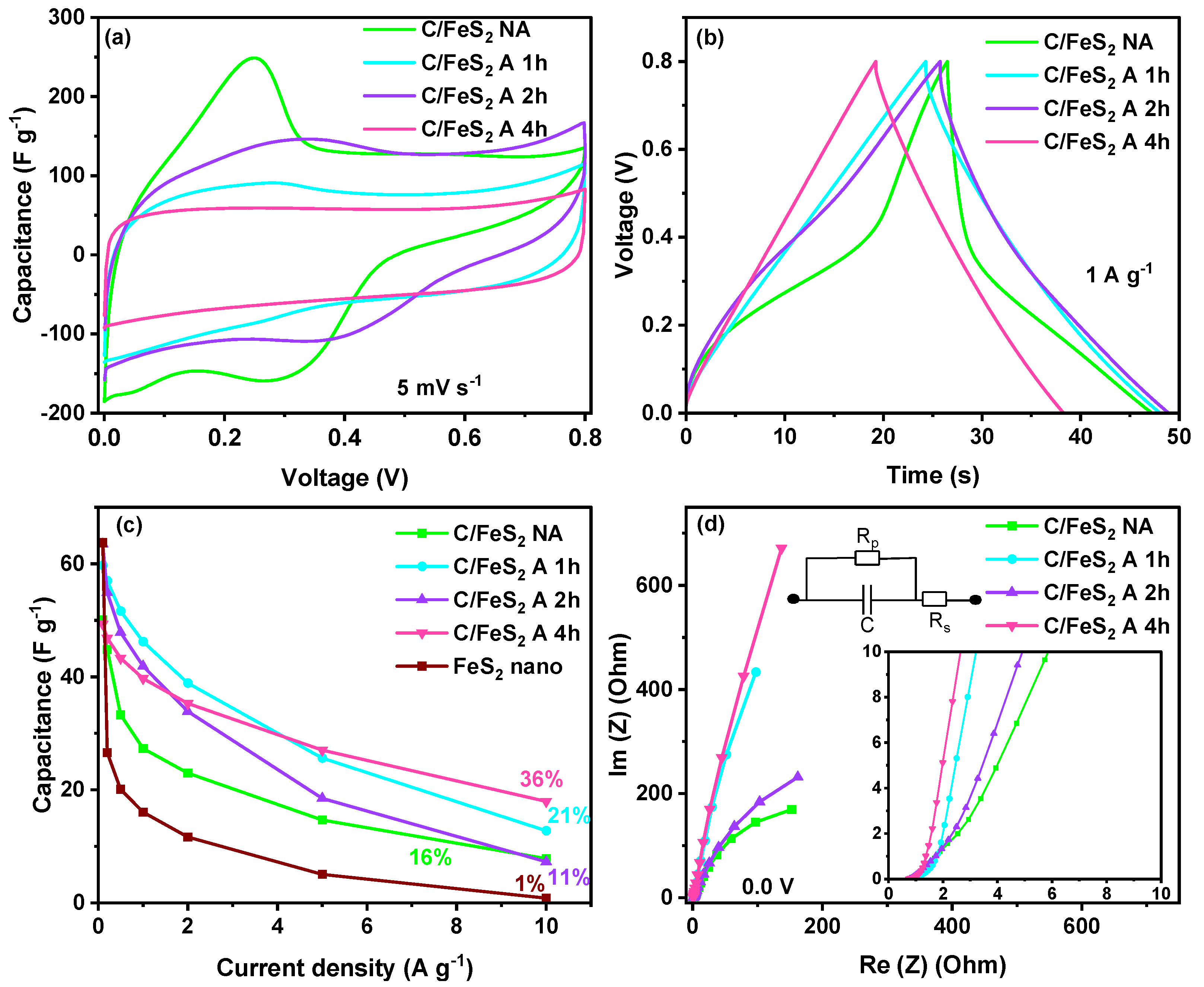
3.2. Electrochemical Characterisation of Activated C/FeS2 Materials

Electrochemical tests were performed with 2 M KOH in a 3-electrode cell to obtain CV data illustrating the redox activity of FeS2, and then in a symmetric 2-electrode cell to evaluate the supercapacitor performance.
Figure 5 shows the CVs of the materials obtained with scan rates of 1 mV s−1 over a potential window ranging from −1.2 to −0.2 V vs. Hg/HgO (Figure 5a). It should be noted that 50 activation cycles were performed at 1 mV s−1 before recording the voltammograms (Figure 5a). The aim of the repetitive cycling was to stabilize the material until it gave a reproducible CV [48]. However, the phenomena that occurred during this step have not been reported in the literature. Therefore, to understand the structural and morphological changes occurring in the material, XRD and STEM were applied to the pristine electrode and again after 50 CV cycles (Figure 5b–d). Compared to the pristine electrode, the FeS2 was preserved, while the Fe7S8 content diminished substantially. Interestingly, a new phase was identified after cycling, i.e., the iron(III) oxide hydroxide Fe(OOH) (COD 9010406). The observed graphite peak (COD 9011577) comes from the conductive glue used on the current collector on the cell. The formation of Fe(OOH) was beneficial because it may enhance the wettability and reversibility during cycling [49]. The High-resolution XPS spectra of the Fe 2p3/2 pristine electrode and of the same electrode after 50 cycles (Figure S7b,c, SI) confirmed the presence of more FeOOH. According to the literature [50], the binding energy of FeOOH is in the same position as that of Fe3O4 (~710 eV), therefore, the contribution of the latter phase cannot be excluded in the pristine electrode. However, the amount of FeOOH after cycling is significantly higher than in pristine material (5.8% vs. 1.1%). In addition, based on the deconvoluted XPS S2p peak (not shown here), the FeS2 amount decreases while Fe7S8 disappears after cycling, in line with XRD observations. Therefore, a part of FeS2/Fe7S8 is transformed in FeOOH, indicating the reason for the increased pseudocapacitive activity, since with more hydrated phases, better reversibility resulted in more developed CV scans (66% increase in the area) (Figure 5a). The STEM images (Figure 5c,d) showed that the particles tended to aggregate during cycling, and distinguishable nanoparticles were no longer observed. This suggested that in contact with the electrolyte, the FeS2 tended to form larger particles that completely covered the surface of the carbon. This will be discussed in detail later.
As shown by the electrochemical data for the materials, (Figure S8, SI) the oxidation and reduction peaks were clearly visible for all materials and occurred at an approximate potential of −0.58 V vs. Hg/HgO for the oxidation peak and at −1.1 V vs. Hg/HgO for the reduction peak. Small shifts in the potentials for oxidation and reduction were seen for some of the materials. According to the literature [19], the redox couple involved in charge storage by FeS2 was the Fe2+/Fe3+ couple, and the reaction proposed for charge storage by pyrite FeS2 is shown in Equation (5) [12]. Moreover, additional redox activity might come from FeOOH (Equation (6)).
F e S 2 + O H F e S 2 O H + H 2 O + e  
F e O O H + H 2 O + e F e ( O H ) + O H  
The areas under the CV curves varied for the different materials (Figure S9, SI); C/FeS2 NA showed the smallest area, probably because it had the lowest SSA. The increased area under the voltammogram was consistent with the textural properties (SSA, pore volume, and width). After 2 h of activation, the SSA and the micropore volume were the highest, and the CV of the material showed the largest area, indicating good electrochemical behaviour. After 4 h, the material had a smaller surface area, but it was still larger than that of C/FeS2 NA. In addition to the textural properties, other parameters influenced the electrochemical behaviour, such as the particle sizes and different types/amounts of crystalline phases and functional groups, which varied from one material to another.
Evaluations were performed with a 2-electrode supercapacitor, as shown in Figure 6. In Figure 6a, the CV obtained for C/FeS2 NA with a scan rate of 5 mV s−1 showed obvious redox peaks that contributed to the capacitance. For the other materials, the shapes were mainly rectangular, indicating capacitive-like behaviour. This suggested that the smallest particle sizes manifested as pseudocapacitance in the cyclic voltammograms and made the peaks more visible. C/FeS2 A 2 h showed the largest areas under the peaks, probably because it had the highest SSA of all the materials.
For a better evaluation at different sweep rates, the CVs of all materials are presented in Figure S9, SI, and the behaviour differed from one material to another. For the material with small particles (C/FeS2 NA, Figure S9a, SI), the behaviour indicated a mixture of capacitive and faradaic contributions. However, with increasing particle sizes and specific surface areas, the redox contribution slowly vanished (Figure S9b,c, SI) until pure capacitive behaviour was observed for C/FeS2 A 4 h (Figure S9d, SI).
To gain a deeper understanding of the different energy storage mechanisms in this system, the power law (I = aVb) was used. This indicates the relationship between the peak current registered (I) and the scan rate (V) and provides insights into the capacitive and pseudocapacitive contributions [51]. If b = 1, the storage mechanism is mainly governed by surface adsorption, i.e., it is capacitive, while for b = 0.5, diffusion mechanisms originating from pseudocapacitance are involved. For this purpose, the value of b was determined by calculating the slope of a linear fit for a plot of Log (I) vs. Log(V), as shown in Figure S10, SI. The intensity of the cathodic peak in the range of 0.2 to 0.4 V was used for this calculation. It can be seen that b increased from 0.7 to 0.93 with an increase in the activation time from 1 h to 4 h.
The pristine C/FeS2 NA had a low b value of 0.7, suggesting a combination of both energy storage mechanisms but with a more significant pseudocapacitive contribution. In contrast, for C/FeS2 A 4 h, b = 0.93, and a rather predominant capacitive contribution was observed with only a small contribution from pseudocapacitive behaviour. This probably arose from the larger pore particles formed that did not block the pores as the small particles did; therefore, the porosity was more accessible. These results were consistent with the STEM and 3-electrode cell results (Figure 5).
The charge discharge curves determined at 1 A g−1 (Figure 6b) exhibited symmetric lines. Once again, the shapes were identical, and triangular, for all materials except C/FeS2 NA, which showed behaviour to that of battery-type electrodes. This behaviour was already reported for graphene/FeS2 rods with lengths of 2 μm and diameters of 50 nm and was attributed to battery-type behaviour [52].
The shapes of the CV curves changed with changes in the particle sizes and electrode thicknesses, as demonstrated, for example, with Nb2O5 [53]. Carbon/FeS2 nanoparticles with bimodal size distributions, i.e., 20–50 nm and 100–200 nm, exhibited faradaic behaviour in a nonaqueous electrolyte [36]. In the present case, although C/FeS2 NA had very small particles (<10 nm), it also had aggregates and exhibited similar behaviour. However, the precise effect of the particle sizes on the CV signatures must be studied further with mono-modal particles to determine their contributions.
Therefore, the capacitances for the various materials were calculated using the GCD technique; in 2 M KOH, the values were 50, 60, 63, and 49 F g−1 at 0.1 A g−1 for C/FeS2 NA, C/FeS2 A 1 h, C/FeS2 A 2 h, and C/FeS2 A 4 h, respectively. The capacitance was determined at different current densities to evaluate the material’s behaviour at high current densities up to 10 A g−1 (Figure 6c). The resulting capacitance retention rates were 16%, 22%, 11%, and 36% for C/FeS2 NA, C/FeS2 A 1 h, C/FeS2 A 2 h, and C/FeS2 A 4 h, respectively. For comparison purposes, unsupported nanosized FeS2 synthesized from nano-Fe2O3 was tested in a symmetric 2-electrode system. This material had a predominant FeS2 marcasite phase, particle sizes of ~50–100 nm, and a surface area of 10 m2 g−1 (Figure S11, SI) and was taken as a representative example for comparison with the C/FeS2 composites. The rate capability (Figure 6c) for nano-FeS2 showed a capacitance of 64 F g−1 at 0.1 A g−1, which was comparable to those for the C/FeS2 materials, but dropped drastically to 27 F g−1 at 0.2 A g−1, and only 1% of the rate capability was retained at 10 F g−1. These results showed that in the absence of carbon, the capacitance loss for FeS2 was more drastic, probably due to the limited electron transport through the material at high current rates. This confirmed that the FeS2 particles supported in carbon improved the supercapacitor performance since the porosity and electronic conductivity are provided.
EIS was used to gain insight into the resistance of the device. The Nyquist plots (Figure 6d) showed two behaviours in the low-frequency region, depending on the material. C/FeS2 A 1 h and C/FeS2 A 4 h exhibited almost vertical, straight lines indicating capacitive materials with high conductivities [54]. However, C/FeS2 NA and C/FeS2 A 2 h showed lines with angles of 45° and shapes similar to half semicircles. This was probably due to internal cell resistance, but also indicated some resistance in the bulk material at low frequencies [55]. In the inset, the high-frequency regime showed similar EIS values of 0.76, 0.86, 0.75, and 0.72 Ω for C/FeS2 NA, C/FeS2 A 1 h, C/FeS2 A 2 h, and C/FeS2 A 4 h, respectively. These values were lower than those for nano-FeS2 (1.02 Ω) and FeS2 electrodes reported in other work (2.88 Ω) [56]. Therefore, the presence of carbon decreased the resistance and enhanced the electronic conductivity.
To develop valid metrics with which to compare supercapacitors, a Ragone plot (energy density vs. power density) is presented in Figure 7a. The energy and power were calculated from the mass of the two electrodes in the symmetric device. C/FeS2 NA had the lowest profile, and the energy vs. power line dropped quickly. C/FeS2 A 1 h and C/FeS2 A 2 h showed higher energies of 1.32 and 1.41 W h kg−1, but their profiles dropped at high power densities. Finally, C/FeS2 A 4 h had the longest horizontal line with an energy density of 1.09 W h kg−1 at 16.32 W kg−1, and it reached a maximum power of 1.3 kW kg−1. A comparison with other types of metal-based electrodes is interesting, and C/FeS2 showed values comparable to those of nickel sulfide [57], copper sulfide [58], and manganese-cobalt sulfides [59].
Since cycling stability is another important criterion for the application of supercapacitors, the nonactivated reference material C/FeS2 NA and the best-performing material, i.e., that activated at 4 h, C/FeS2 A 4 h, were selected for this purpose. The long-term cycling performance was evaluated at up to 0.8 V with a current density of 1 A g−1 in the 2-electrode cell. In the first 2000 cycles, the capacitances of C/FeS2 1 h and C/FeS2 A 4 h increased. Similar behaviour was reported in previous studies [60] and was attributed to the activation of the redox species [7], as discussed above for the 3-electrode cell, but no other insights were provided.
After the capacitance increased during the first 2000 cycles, nearly identical capacitance was observed until cycle 10,000 (Figure 7b). This stable behaviour for more than 8000 cycles led us to predict that the cycle lives of these materials were still very high. To gain a better understanding of the cycling behaviour, STEM and XRD were applied to the pristine electrode and the same electrode after 10,000 cycles (Figure 7c,d and Figure S12, SI). As with the 3-electrode test, there was a progressive modification in the morphology during cycling. After 10,000 cycles, the particles looked like needles or sheets, and their sizes increased slightly but remained rather small. Moreover, the pyrite phase in the material was preserved, while the Fe7S8 phase was drastically diminished (Figure S12, SI). This increased the capacitance and was beneficial for long-term cycling.
The various electrochemical tests allowed us to conclude that C/FeS2 A 4 h showed the best behaviour. First, it had the best rate capability of 36%, which was highly encouraging for a TMS material, and it showed values between 15 and ~40% [60]. The energy vs. power profile was steady, demonstrating efficient energy storage. Additionally, long-term cycling was steady for at least 10,000 cycles. All of these good results can be attributed to the characteristics of the material. First, it had a high proportion of the pyrite FeS2 phase, which was not the case for the other materials. Second, the pyrite particles were the largest of the materials, but their average size did not exceed 20 nm. Finally, this material showed the highest percentage of sulfur, which may have increased the pseudocapacitance. Therefore, the synthesis procedure and thermal treatment conditions shaped and tuned the structure, functional groups, conductivity, and textural properties of the material. Table S1 presents a comparison with some composites reported in the literature. The comparisons were not absolute, as many parameters were different, including the type of cell (most of them used 3 electrode cells), the voltage window, and the current density at which cycling was performed. Therefore, it can be said that comparisons of the synthesized C/FeS2 should only be conducted using 2-electrode cells and similar conditions.

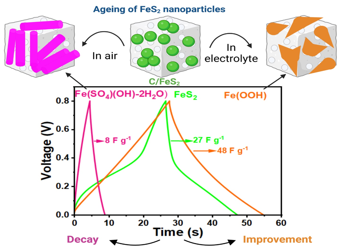
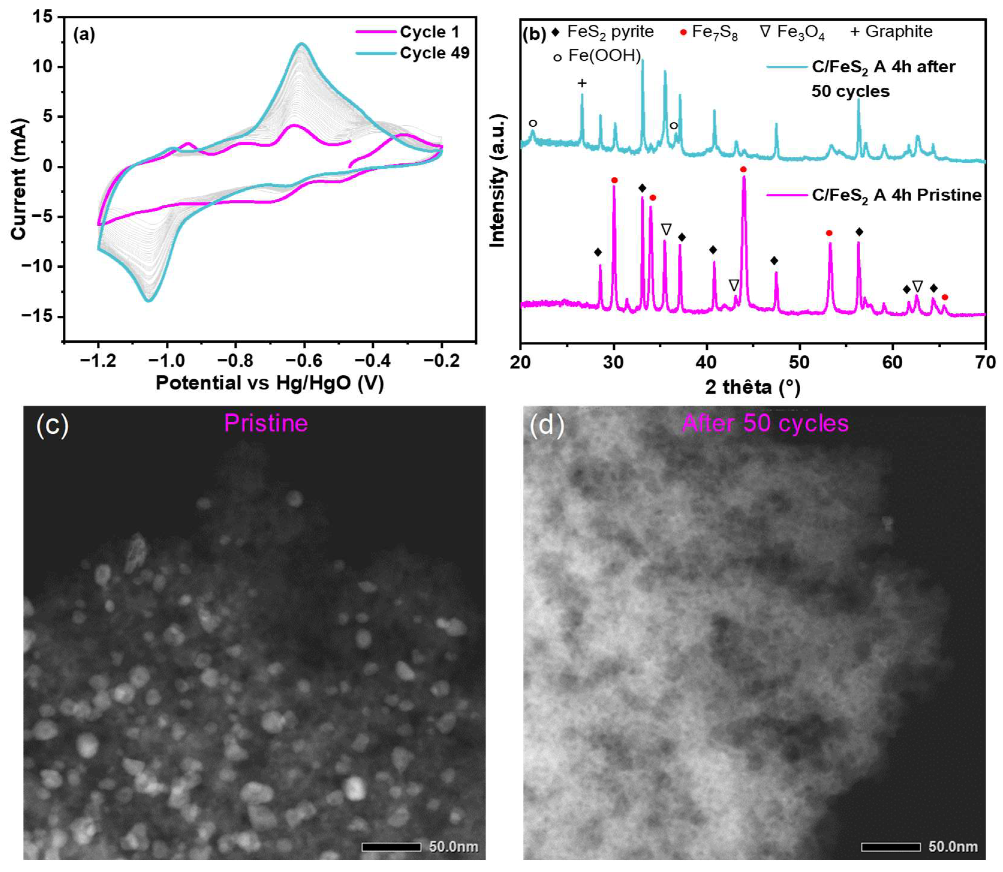
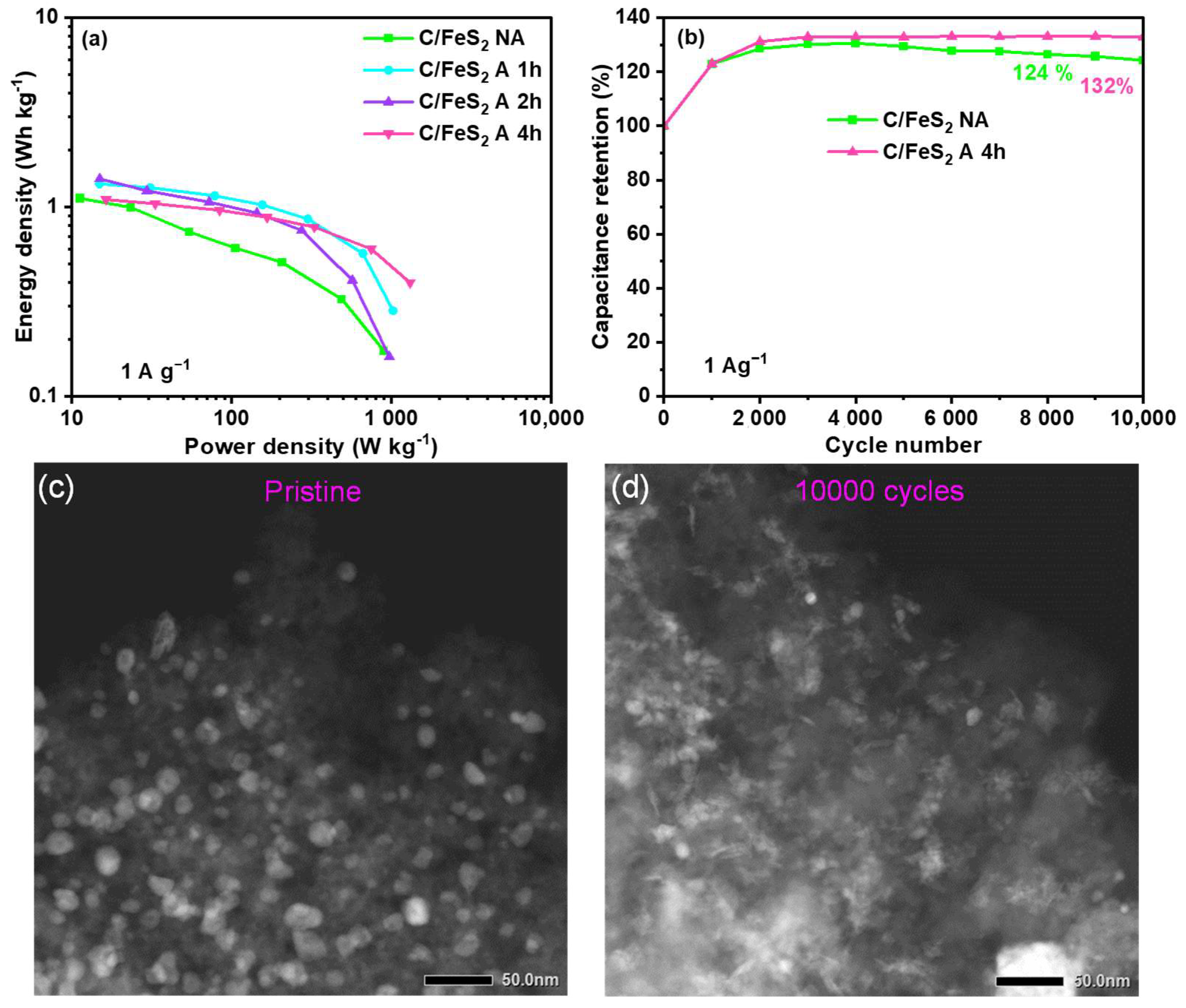
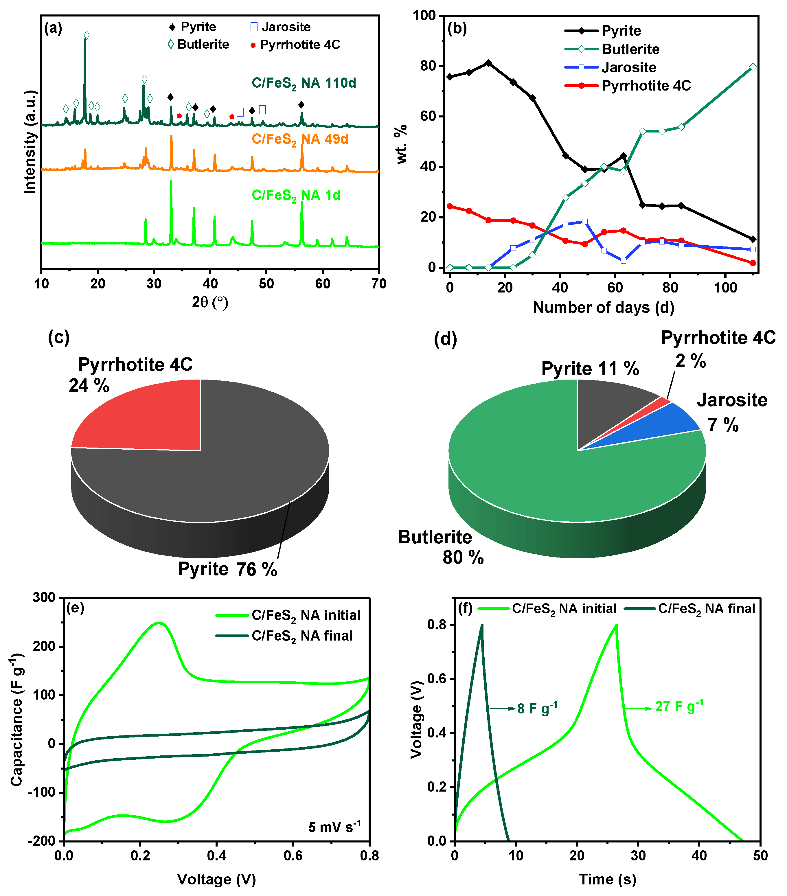
3.3. Ageing of C/FeS2 over Time

The stability of FeS2 in its different allotropic forms (marcasite or pyrite) is a research topic of interest. Therefore, attempts have been made to prepare air-stable FeS2 [61]; however, most studies were focused on large-scale pyrite for photovoltaics or environmental applications [61,62]. No reports have been found on nanosized FeS2 (<20 nm) in the literature, and possible modifications of the structural, morphological, and electrochemical properties triggered by oxidation, hydration, etc., are not known, which motivated this work.
Therefore, the emphasis herein was on the evolution of nano-FeS2 over time. In this case, the C/FeS2 NA composite powder, which had the smallest particle sizes, was selected for detailed evaluation. In the first step, the sample was placed in a sample holder under ambient conditions and characterised by XRD and TEM weekly over a period of two months. Aggregation and volume expansion were observed over time; therefore, the material was realigned to perform another XRD experiment after two additional months (110d in total). After this period of 110d, the material was immediately tested in a symmetric 2-electrode cell to compare its performance with that of the initial material (1d).
Figure 8 contains the diffractograms and electrochemical data generated after the selected time intervals. The XRD data (Figure 8a) show that in the initial state (1d), the material contained pyrite FeS2 (COD 9000594) as the main phase and Fe7S8 pyrrhotite 4C (COD 2104739). With increased ageing (49d and 110d), new crystalline phases emerged, i.e., hydrated iron sulfates such as jarosite (H3O)Fe3(SO4)2(OH)6 (COD 9007285) and butlerite Fe(SO4)(OH)-2H2O (COD 9000225). A possible chemical reaction pathway is shown in Equation (9) [63]:
F e S 2 + 8   H 2 O + 7   O 2 F e S O 4   7   H 2 O + S O 4 2 + 2   H +  
Density functional theory studies indicated that pyrite oxidation may be related to different environmental issues. Depending on the activation energy, either iron oxides or iron sulfates are formed [64]. The evolutions of these species were followed over time with XRD spectra (not shown for simplicity), as shown in Figure 8b.
The initial composition (75% pyrite and 25% pyrrhotite 4c) remained stable for approximately 20d, and then the jarosite phase appeared after ~18d, followed by butlerite after ~24d. At 30d, butlerite evolution increased significantly with time until it reached 80%, while the jarosite proportion remained rather stable (~20%). The proportion of the pyrrhotite 4C phase decreased slowly and continuously from 24 to 2% on 110d.
The STEM was performed on the final material to provide a better understanding of the morphological modifications (Figure S13, SI), and there were drastic modifications to the initial material, presented in Figure 3a. After ageing, there was no sign of individual particles, and the previous small particles all aggregated to form structures that looked like long fibres or filaments. This may have been due to the growth of hydrated particles along a preferred direction in the porous carbon. Wiese et al. observed the spontaneous formation of hydrated iron sulfates from pyrite samples [63]. This was accompanied by a significant change in the morphology and formation of a new material shape. The modification depended on many factors, including the degree of crystallization, since less crystalline materials are more prone to oxidation. From the TEM images (Figure S13, SI), it is difficult to distinguish between the carbon matrix and the new forms of hydrated sulfate, as these new particles were spread everywhere on the carbon surface. Therefore, the broad dispersion of the particles in the initial material was no longer present after 110d. The morphological evolution and the changes in distribution may have impacted the electrochemical performance because ion diffusion and transport will have different pathways.
The initial materials contained 75% pyrite (Figure 8c), while only 11% was preserved after 110d (Figure 8d). A significant decrease in the amount of FeS2 could have affected the performance. In Figure 8e, a CV generated for the aged material showed different behaviour. After ageing, no redox activity was observed even at low scan rates, and the shape of the CV curve was rectangular, originating only a carbon contribution. This suggested that the newly formed hydrated phases were not electrochemically active. Furthermore, this showed that a significant part of the capacitance in the initial material arose from FeS2, even if the composite was not purely composed of FeS2 (75%). Nevertheless, it is also possible that the growth of these structures blocked the pores; therefore, carbon contributed less to the CV as well. The charge–discharge curves (Figure 8f) also showed differences after ageing. The curves exhibited triangular shapes, attesting to the presence of carbon and its capacitive contribution, whereas there was no redox activity. Moreover, the capacitance decreased by almost two-thirds after ageing (8 vs. 27 F g−1).

4. Discussions

The synthesis of the C/FeS2 composites is advantageous due to the one-pot approach using cysteine that allows a direct FeS formation. Further H2S treatment was required to convert FeS to FeS2. The optimisation of the sulfidation temperature between 250 and 600 °C for 3 h allowed to determine the optimal temperature for FeS2 formation (400 °C), which is a compromise between the FeS conversion to FeS2 (at low temperatures) and the FeS2 decomposition to FeS (at high temperatures). In a previous report, FeS2 pyrite was synthesized at 200 °C on graphene sheets through a 24 h thermal treatment with H2S [65]. However, in the present case, the FeS particles are confined in carbon, which changes the kinetics of their transformation into FeS2. Consequently, the synthesis of pyrite by sulfidation is complex. Depending on the initial properties of the materials, there is a compromise between kinetics and thermodynamics, as discussed elsewhere [62].
The as-obtained C/FeS2 NA composite presented a small FeS2 particle size (7 nm) and a BET surface area of 161 m2 g−1. To enhance the specific surface area in order to improve the capacitance, an activation step was implemented prior to the sulfidation. CO2 activation is a known pathway to increase the specific surface area [66], and the effect of activation time (1 to 4 h) on C/FeS2 formation was studied. This allowed to enhance the specific surface area, in particular, the BET surface was almost doubled (296 m2 g−1) after 2 h of activation, then a decrease was observed. The increase in activation time has also led to an increase in the size of the FeS2 particles, from 7 to 17 nm, and to the forming of aggregates of particles, in agreement with other works [67]. The size and location of these particles in the carbon network could affect not only the porosity of the composites but also the interactions with the electrolyte. Additionally, the duration of activation induced the FeS oxidation to Fe3O4, which inhibits FeS2 formation. For this reason, the C/FeS2 4 h material contained the highest amount of Fe3O4 after activation, therefore, it was sulfidated for a longer time (6 h) compared to that of the other composites (3 h). Consequently, this material presented the highest amount of FeS2 and a lower content of residual phases such as Fe7S8 and Fe3O4. Due to the presence of the latter phases, the precise quantification of the amount of FeS2 in the composites was complex and estimated to be between 15 and 23%, depending on the composite.
The various electrochemical tests showed a general trend for an increase in the capacitance (50 to 63 F g−1 at 0.1 A g−1) with the increase of BET surface area (161 to 296 m2 g−1) for the different C/FeS2 composites, from NA to 2 h of activation. Then, for the 4 h activated material, there is a decrease in both BET surface area (214 m2 g−1) and the capacitance (49 F g−1). This suggests that the capacitance follows the variation of the BET surface area, in line with the known knowledge on pure carbon materials [68]. However, for the latter material, there is a greater amount of S in the carbon network, larger particles, and more amount of FeS2. Therefore, data should be carefully analysed since other parameters might affect the capacitance in composite materials [69]. In particular, the pseudo-capacitive contribution from FeS2 nanoparticles should be considered. This depends on the amount of FeS2, but also on particle size and distribution. Indeed, different electrochemical behaviours were observed depending on the particle size, i.e., the small particles (C/FeS2 NA) revealed a rather faradic (battery-like) behaviour, while the larger particles (the other composites) showed pseudo-capacitive behaviour. The modification of the capacitance with the particle size has already been observed, but the charge storage mechanism behind it remains a challenge to be fully understood. Therefore, the capacitance is related to the properties of both carbon and FeS2 [53].
If the other metrics are analysed, the C/FeS2 A 4 h appears to present the best behaviour. First, it has the best rate capability of 36%, which is highly encouraging for a TMS material, that showed values between 15 and ~40% [70]. The energy vs. power profile was steady, demonstrating efficient energy storage. Furthermore, long-term cycling was stable for at least 10,000 cycles. All of these good results can be attributed to the characteristics of the material. First, it has a high proportion of the pyrite FeS2 phase, which was not the case for the other materials. Second, the pyrite particles were the largest of the materials, but their average size did not exceed 20 nm. Finally, this material showed the highest percentage of sulfur, which may have increased the pseudocapacitance. Therefore, the synthesis procedure and the thermal treatment conditions shaped and tuned the structure, functional groups, conductivity, and textural properties of the material.
Table S1 presents a comparison to some C/FeS2 composites reported in the literature. The comparisons were not absolute, as many parameters were different, including the type of cell, the voltage window, and the current density at which cycling was performed [7,35]. Most of the works reported the performance of only 3-electrode cells leading to overestimated values compared to synthesized C/FeS2. Moreover, such tests in 3-electrodes are not representative of supercapacitor performance and should be conducted with 2-electrode cells. Furthermore, if the performance is compared to the unsupported FeS2 nanoparticle, the C/FeS2 composites behave much better. In particular, the carbon network improved the capacitance retention of composite materials, probably due to its higher conductivity and porosity compared to FeS2. Nevertheless, the capacitance of the C/FeS2 composites is still lower compared to that of pure carbon [71]. Strategies to improve the performance of C/FeS2 composites might include the increase of the FeS2 content in the composites, the formation of a pure FeS2 phase, better control of particle size, and the modification of particle shape. More importantly, an understanding of FeS2 storage mechanisms should also allow one to enhance performance. In this direction, this study showed an atypical electrochemical behavior during the cycling of the materials. A progressive increase in capacitance over cycling occurred, and post-mortem analyses evidenced the formation of FeOOH. This newly born phase from the interaction with the electrolyte with iron-based species (most probably Fe7S8 or/and iron oxide) positively impacted the electrochemical performance. This was associated with the redox activity of the FeOOH material [72]. Therefore, both the FeS2 and FeOOH contributed to the capacitance through pseudo-capacitive reactions, whereas carbon did so through electrostatic interactions (porosity) and pseudocapacitance (S-doping).
Another important aspect that strongly affected the performance was the chemical state of the FeS2 particle. On the basis of the results obtained herein, one may say that the storage of nanoscale pyrite particles (7.0 nm for C/FeS2 NA) under ambient laboratory conditions led to the substantial modification of the structure and morphology of the material. Pyrite was converted in the hydrated iron hydroxy sulphate phase over time. The particles, initially present in the nanoscale range and highly dispersed in the carbon matrix, were no longer ensured overtime. The surface of carbon was covered by the newly formed phase, blocking, most likely, the carbon porosity. These modifications directly impacted the electrochemical behaviour and led to the formation of inactive phases and low performance. In summary, very small pyrite nanoparticles (C/FeS2 NA) are not air-stable and should be kept in an anaerobic atmosphere, i.e., a glove box. The activated C/FeS2 A 4 h composite showed different behaviour, i.e., it was much more stable and exhibited less phase evolution after ageing for days, as shown in Figure S14a, probably due to the larger and more stable particles. Unsupported nano-FeS2 showed fast conversion to hydrated sulfate phases FeSO4·H2O and FeSO4·4H2O beginning on 7d (from 87% to 33% FeS2) and then gradually converted (only 12% of the FeS2 remained after 70d), as observed in Figure S14b,c, SI. This distinct degradation pathway for nano-FeS2 compared to C/FeS2 NA might suggest that, in the absence of carbon, the particles were even more prone to degradation. Therefore, both the sizes of the FeS2 particles and the surrounding environment affected the stability in air.

5. Conclusions

The current study described the syntheses of C/FeS2 nanocomposites via one-pot routes, their evaluations as electrodes in supercapacitors, and the effects of ageing on their properties and performance. First, the mixing of all precursors followed by a carbonization step formed the C/FeS nanocomposites, whereas sulfidation under H2S provided C/FeS2. The sulfidation process was optimized, and the optimal temperature was 400 °C. In addition, the physical activation was conducted with CO2 for 1 to 4 h and led to increases in the porosity up to 2 h then a slight decrease was observed while the FeS2 nanoparticle sizes increased (from 7 to 17 nm). The evaluation of the nano-C/FeS2 materials for use as supercapacitor electrodes was performed in a symmetric device. The capacitance generally improved with increasing activation time and active surface area, although the particle sizes also affected the performance. The C/FeS2 A 4 h material exhibited the best compromise among the improved capacitance, rate capability, energy and power density, as well as cycling stability. This occurred because it had the richest pyrite phase with the largest nanoparticles, along with the highest amount of sulfur in the carbon. The ageing of the nanopyrite composites during electrochemical cycling and under atmospheric conditions was first studied using XRD and TEM. After cycling, hydrated forms of iron oxide were formed and contributed to the capacitance by expanding the CV shapes generated with the 3-electrode cell. The morphology changed progressively during cycling but was not detrimental to the electrochemical behaviour, as observed with long-term cycling. However, under air, the progressive conversion of the iron sulfide into hydrated iron hydroxy sulfate occurred, which was accompanied by a morphology change from spherical to fibrous. These new phases were electrochemically inactive and probably had obstructed carbon pores leading to a very weak performance. For future investigations, controlling the phase crystallinity during the activation/sulfidation can be beneficial. The size/shape of the particles can also be optimized for better stability during ageing. Finally, the content of FeS2 in the composites can be increased, with special attention given to porosity conservation. In summary, this work shows the importance of understanding the fundamental phenomena occurring at the interface between the electrode and the air/electrolyte to enhance the performance of C/FeS2 materials in supercapacitors.

Supplementary Materials

The following supporting information can be downloaded at: https://www.mdpi.com/article/10.3390/c9040112/s1, XRD and TGA experimental details; XRD C/FeS composites; particle size of C/FeS after activation; STEM and TGA of C/FeS2; XRD of residue obtained from TGA; XPS of C/FeS2; CV of C/FeS2 in three- and two-electrode cells; correlation of peak current vs scan rate for C/FeS2; characterization of nano FeS2; XRD before and after long cycling of C/FeS2; literature table comparing the performance of C/FeS2; STEM of C/FeS2 after aging in air; XRD semi-quantitative analyses [7,11,12,13,29,35].

Author Contributions

Conceptualization, S.Z. and J.-M.L.M.; methodology, S.Z., B.R., J.-M.L.M. and C.M.G.; software, S.Z. and P.F.; validation, C.M.G.; formal analysis, S.Z. and M.Y.N.; investigation, S.Z., B.R., M.Y.N. and P.F.; resources, C.M.G.; data curation, S.Z. and P.F.; writing—original draft preparation, S.Z.; writing—review and editing, J.-M.L.M. and C.M.G.; visualization, S.Z., J.-M.L.M. and C.M.G.; supervision, J.-M.L.M. and C.M.G.; project administration, S.Z. and C.M.G.; funding acquisition, C.M.G. All authors have read and agreed to the published version of the manuscript.

Funding

The authors thank the Université de Haute Alsace (UHA) and the French National Research Agency (STORE-EX Labex Project ANR-10-LABX-76-01) for the financial support of this work.

Data Availability Statement

Data are contained within the article and Supplementary Materials.

Acknowledgments

We thank L. Vidal for their technical help with the STEM analysis and Samar Hajjar-Garreau for their technical assistance with the XPS analyses.

Conflicts of Interest

The authors declare no conflict of interest.

References

  1. Frąckowiak, E.; Płatek-Mielczarek, A.; Piwek, J.; Fic, K. Advanced Characterization Techniques for Electrochemical Capacitors. Adv. Inorg. Chem. 2022, 79, 151–207. [Google Scholar] [CrossRef]
  2. An, C.; Zhang, Y.; Guo, H.; Wang, Y. Metal Oxide-Based Supercapacitors: Progress and Prospectives. Nanoscale Adv. 2019, 1, 4644–4658. [Google Scholar] [CrossRef] [PubMed]
  3. Gao, Y.; Zhao, L. Review on Recent Advances in Nanostructured Transition-Metal-Sulfide-Based Electrode Materials for Cathode Materials of Asymmetric Supercapacitors. Chem. Eng. J. 2022, 430, 132745. [Google Scholar] [CrossRef]
  4. Yu, S.; Ng, V.M.H.; Wang, F.; Xiao, Z.; Li, C.; Kong, L.B.; Que, W.; Zhou, K. Synthesis and Application of Iron-Based Nanomaterials as Anodes of Lithium-Ion Batteries and Supercapacitors. J. Mater. Chem. A 2018, 6, 9332–9367. [Google Scholar] [CrossRef]
  5. Huang, Y.; Zhao, H.; Bao, S.; Yin, Y.; Zhang, Y.; Lu, J. Hollow FeS2 Nanospheres Encapsulated in N/S Co-Doped Carbon Nanofibers as Electrode Material for Electrochemical Energy Storage. J. Alloys Compd. 2022, 905, 164184. [Google Scholar] [CrossRef]
  6. Balakrishnan, B.; Balasingam, S.K.; Sivalingam Nallathambi, K.; Ramadoss, A.; Kundu, M.; Bak, J.S.; Cho, I.H.; Kandasamy, P.; Jun, Y.; Kim, H.-J. Facile Synthesis of Pristine FeS2 Microflowers and Hybrid rGO-FeS2 Microsphere Electrode Materials for High Performance Symmetric Capacitors. J. Ind. Eng. Chem. 2019, 71, 191–200. [Google Scholar] [CrossRef]
  7. Pei, L.; Yang, Y.; Chu, H.; Shen, J.; Ye, M. Self-Assembled Flower-like FeS2/Graphene Aerogel Composite with Enhanced Electrochemical Properties. Ceram. Int. 2016, 42, 5053–5061. [Google Scholar] [CrossRef]
  8. Lai, C.-H.; Lu, M.-Y.; Chen, L.-J. Metal Sulfide Nanostructures: Synthesis, Properties and Applications in Energy Conversion and Storage. J. Mater. Chem. 2012, 22, 19–30. [Google Scholar] [CrossRef]
  9. Venkateshalu, S.; Goban Kumar, P.; Kollu, P.; Jeong, S.K.; Grace, A.N. Solvothermal Synthesis and Electrochemical Properties of Phase Pure Pyrite FeS2 for Supercapacitor Applications. Electrochim. Acta 2018, 290, 378–389. [Google Scholar] [CrossRef]
  10. Iqbal, M.F.; Ashiq, M.N.; Zhang, M. Design of Metals Sulfides with Carbon Materials for Supercapacitor Applications: A Review. Energy Technol. 2021, 9, 2000987. [Google Scholar] [CrossRef]
  11. Wang, Y.; Zhang, M.; Ma, T.; Pan, D.; Li, Y.; Xie, J.; Shao, S. A High-Performance Flexible Supercapacitor Electrode Material Based on Nano-Flowers-like FeS2/NSG Hybrid Nanocomposites. Mater. Lett. 2018, 218, 10–13. [Google Scholar] [CrossRef]
  12. Sridhar, V.; Park, H. Carbon Nanofiber Linked FeS2 Mesoporous Nano-Alloys as High Capacity Anodes for Lithium-Ion Batteries and Supercapacitors. J. Alloys Compd. 2018, 732, 799–805. [Google Scholar] [CrossRef]
  13. Liu, X.; Deng, W.; Liu, L.; Wang, Y.; Huang, C.; Wang, Z. Passion Fruit-like Microspheres of FeS2 Wrapped with Carbon as an Excellent Fast Charging Material for Supercapacitors. New J. Chem. 2022, 46, 11212–11219. [Google Scholar] [CrossRef]
  14. Wang, F.; Li, G.; Zhou, Q.; Zheng, J.; Yang, C.; Wang, Q. One-Step Hydrothermal Synthesis of Sandwich-Type NiCo2S4@reduced Graphene Oxide Composite as Active Electrode Material for Supercapacitors. Appl. Surf. Sci. 2017, 425, 180–187. [Google Scholar] [CrossRef]
  15. Zallouz, S.; Réty, B.; Vidal, L.; Le Meins, J.-M.; Matei Ghimbeu, C. Co3O4 Nanoparticles Embedded in Mesoporous Carbon for Supercapacitor Applications. ACS Appl. Nano Mater. 2021, 4, 5022–5037. [Google Scholar] [CrossRef]
  16. Jahel, A.; Ghimbeu, C.M.; Monconduit, L.; Vix-Guterl, C. Confined Ultrasmall SnO2 Particles in Micro/Mesoporous Carbon as an Extremely Long Cycle-Life Anode Material for Li-Ion Batteries. Adv. Energy Mater. 2014, 4, 1400025. [Google Scholar] [CrossRef]
  17. Theerthagiri, J.; Senthil, R.A.; Nithyadharseni, P.; Lee, S.J.; Durai, G.; Kuppusami, P.; Madhavan, J.; Choi, M.Y. Recent Progress and Emerging Challenges of Transition Metal Sulfides Based Composite Electrodes for Electrochemical Supercapacitive Energy Storage. Ceram. Int. 2020, 46, 14317–14345. [Google Scholar] [CrossRef]
  18. Zardkhoshoui, A.M.; Davarani, S.S.H.; Ashtiani, M.M.; Sarparast, M. Designing an Asymmetric Device Based on Graphene Wrapped Yolk–Double Shell NiGa2S4 Hollow Microspheres and Graphene Wrapped FeS2–FeSe2 Core–Shell Cratered Spheres with Outstanding Energy Density. J. Mater. Chem. A 2019, 7, 10282–10292. [Google Scholar] [CrossRef]
  19. Chen, Y.-C.; Shi, J.-H.; Hsu, Y.-K. Multifunctional FeS2 in Binder-Independent Configuration as High-Performance Supercapacitor Electrode and Non-Enzymatic H2O2 Detector. Appl. Surf. Sci. 2020, 503, 144304. [Google Scholar] [CrossRef]
  20. Dong, H.; Li, L.; Wang, Y.; Ning, Q.; Wang, B.; Zeng, G. Aging of Zero-Valent Iron-Based Nanoparticles in Aqueous Environment and the Consequent Effects on Their Reactivity and Toxicity. Water Environ. Res. 2020, 92, 646–661. [Google Scholar] [CrossRef]
  21. Zallouz, S.; Meins, J.-M.L.; Ghimbeu, C.M. Alkaline Hydrogel Electrolyte from Biosourced Chitosan to Enhance the Rate Capability and Energy Density of Carbon-Based Supercapacitors. Energy Adv. 2022, 1, 1051–1064. [Google Scholar] [CrossRef]
  22. Beda, A.; Villevieille, C.; Taberna, P.-L.; Simon, P.; Ghimbeu, C.M. Self-Supported Binder-Free Hard Carbon Electrodes for Sodium-Ion Batteries: Insights into Their Sodium Storage Mechanisms. J. Mater. Chem. A 2020, 8, 5558–5571. [Google Scholar] [CrossRef]
  23. Bujewska, P.; Gorska, B.; Fic, K. Redox Activity of Selenocyanate Anion in Electrochemical Capacitor Application. Synth. Met. 2019, 253, 62–72. [Google Scholar] [CrossRef]
  24. Wickramaratne, N.P.; Perera, V.S.; Ralph, J.M.; Huang, S.D.; Jaroniec, M. Cysteine-Assisted Tailoring of Adsorption Properties and Particle Size of Polymer and Carbon Spheres. Langmuir 2013, 29, 4032–4038. [Google Scholar] [CrossRef] [PubMed]
  25. Ghimbeu, C.M.; Vidal, L.; Delmotte, L.; Meins, J.-M.L.; Vix-Guterl, C. Catalyst-Free Soft-Template Synthesis of Ordered Mesoporous Carbon Tailored Using Phloroglucinol/Glyoxylic Acid Environmentally Friendly Precursors. Green Chem. 2014, 16, 3079–3088. [Google Scholar] [CrossRef]
  26. Ghimbeu, C.M.; Sopronyi, M.; Sima, F.; Delmotte, L.; Vaulot, C.; Zlotea, C.; Paul-Boncour, V.; Meins, J.-M.L. One-Pot Laser-Assisted Synthesis of Porous Carbon with Embedded Magnetic Cobalt Nanoparticles. Nanoscale 2015, 7, 10111–10122. [Google Scholar] [CrossRef]
  27. Sun, S.; Matei Ghimbeu, C.; Janot, R.; Le Meins, J.-M.; Cassel, A.; Davoisne, C.; Masquelier, C.; Vix-Guterl, C. One-Pot Synthesis of LiFePO4–Carbon Mesoporous Composites for Li-Ion Batteries. Microporous Mesoporous Mater. 2014, 198, 175–184. [Google Scholar] [CrossRef]
  28. Kiener, J.; Girleanu, M.; Ersen, O.; Parmentier, J. Direct Insight into the Confinement Effect of WS2 Nanostructures in an Ordered Carbon Matrix. Cryst. Growth Des. 2020, 20, 2004–2013. [Google Scholar] [CrossRef]
  29. Gražulis, S.; Chateigner, D.; Downs, R.T.; Yokochi, A.F.T.; Quirós, M.; Lutterotti, L.; Manakova, E.; Butkus, J.; Moeck, P.; Le Bail, A. Crystallography Open Database—An Open-Access Collection of Crystal Structures. J. Appl. Cryst. 2009, 42, 726–729. [Google Scholar] [CrossRef]
  30. Elliot, A.D. Structure of Pyrrhotite 5C (Fe9S10). Acta Cryst. B 2010, 66, 271–279. [Google Scholar] [CrossRef]
  31. Li, Y.; van Santen, R.A.; Weber, T. High-Temperature FeS–FeS2 Solid-State Transitions: Reactions of Solid Mackinawite with Gaseous H2S. J. Solid State Chem. 2008, 181, 3151–3162. [Google Scholar] [CrossRef]
  32. Grønvold, F.; Westrum, E.F. Heat Capacities of Iron Disulfides Thermodynamics of Marcasite from 5 to 700 K, Pyrite from 300 to 780 K, and the Transformation of Marcasite to Pyrite. J. Chem. Thermodyn. 1976, 8, 1039–1048. [Google Scholar] [CrossRef]
  33. Zhang, T.; Walawender, W.P.; Fan, L.T.; Fan, M.; Daugaard, D.; Brown, R.C. Preparation of Activated Carbon from Forest and Agricultural Residues through CO2 Activation. Chem. Eng. J. 2004, 105, 53–59. [Google Scholar] [CrossRef]
  34. De Groote, A.M.; Froment, G.F.; Kobylinski, T. Synthesis Gas Production from Natural Gas in a Fixed Bed Reactor with Reversed Flow. Can. J. Chem. Eng. 1996, 74, 735–742. [Google Scholar] [CrossRef]
  35. Huang, Y.; Bao, S.; Yin, Y.; Lu, J. Three-Dimensional Porous Carbon Decorated with FeS2 Nanospheres as Electrode Material for Electrochemical Energy Storage. Appl. Surf. Sci. 2021, 565, 150538. [Google Scholar] [CrossRef]
  36. Tung Pham, D.; Paul Baboo, J.; Song, J.; Kim, S.; Jo, J.; Mathew, V.; Hilmy Alfaruqi, M.; Sambandam, B.; Kim, J. Facile Synthesis of Pyrite (FeS2/C) Nanoparticles as an Electrode Material for Non-Aqueous Hybrid Electrochemical Capacitors. Nanoscale 2018, 10, 5938–5949. [Google Scholar] [CrossRef]
  37. Jahel, A.; Ghimbeu, C.M.; Darwiche, A.; Vidal, L.; Hajjar-Garreau, S.; Vix-Guterl, C.; Monconduit, L. Exceptionally Highly Performing Na-Ion Battery Anode Using Crystalline SnO2 Nanoparticles Confined in Mesoporous Carbon. J. Mater. Chem. A 2015, 3, 11960–11969. [Google Scholar] [CrossRef]
  38. Voorhees, P.W. The Theory of Ostwald Ripening. J. Stat. Phys. 1985, 38, 231–252. [Google Scholar] [CrossRef]
  39. Sing, K.S.W. Reporting Physisorption Data for Gas/Solid Systems with Special Reference to the Determination of Surface Area and Porosity (Recommendations 1984). Pure Appl. Chem. 1985, 57, 603–619. [Google Scholar] [CrossRef]
  40. Sing, K.S.W.; Williams, R.T. Physisorption Hysteresis Loops and the Characterization of Nanoporous Materials. Adsorpt. Sci. Technol. 2004, 22, 773–782. [Google Scholar] [CrossRef]
  41. Chmiola, J. Anomalous Increase in Carbon Capacitance at Pore Sizes Less Than 1 Nanometer. Science 2006, 313, 1760–1763. [Google Scholar] [CrossRef] [PubMed]
  42. Fu, Y.; Zhang, Y.; Li, G.; Zhang, J.; Guo, Y. NO Removal Activity and Surface Characterization of Activated Carbon with Oxidation Modification. J. Energy Inst. 2017, 90, 813–823. [Google Scholar] [CrossRef]
  43. Shaheen Shah, S.; Abu Nayem, S.M.; Sultana, N.; Saleh Ahammad, A.J.; Abdul Aziz, M. Preparation of Sulfur-Doped Carbon for Supercapacitor Applications: A Review. ChemSusChem 2022, 15, e202101282. [Google Scholar] [CrossRef] [PubMed]
  44. Lee, W.; Moon, J.H. Monodispersed N-Doped Carbon Nanospheres for Supercapacitor Application. ACS Appl. Mater. Interfaces 2014, 6, 13968–13976. [Google Scholar] [CrossRef]
  45. Li, X.; Jiang, Y.; Wang, P.; Mo, Y.; Lai, W.; Li, Z.; Yu, R.; Du, Y.; Zhang, X.; Chen, Y. Effect of the Oxygen Functional Groups of Activated Carbon on Its Electrochemical Performance for Supercapacitors. New Carbon Mater. 2020, 35, 232–243. [Google Scholar] [CrossRef]
  46. Moussa, G.; Hajjar-Garreau, S.; Taberna, P.-L.; Simon, P.; Matei Ghimbeu, C. Eco-Friendly Synthesis of Nitrogen-Doped Mesoporous Carbon for Supercapacitor Application. C—J. Carbon Res. 2018, 4, 20. [Google Scholar] [CrossRef]
  47. Kiciński, W.; Dziura, A. Heteroatom-Doped Carbon Gels from Phenols and Heterocyclic Aldehydes: Sulfur-Doped Carbon Xerogels. Carbon 2014, 75, 56–67. [Google Scholar] [CrossRef]
  48. Chen, J.; Zhou, X.; Mei, C.; Xu, J.; Zhou, S.; Wong, C.-P. Pyrite FeS2 Nanobelts as High-Performance Anode Material for Aqueous Pseudocapacitor. Electrochim. Acta 2016, 222, 172–176. [Google Scholar] [CrossRef]
  49. Zhao, S.; Song, Z.; Qing, L.; Zhou, J.; Qiao, C. Surface Wettability Effect on Energy Density and Power Density of Supercapacitors. J. Phys. Chem. C 2022, 126, 9248–9256. [Google Scholar] [CrossRef]
  50. Biesinger, M.C.; Lau, L.W.M.; Gerson, A.R.; Smart, R.S.C. Resolving Surface Chemical States in XPS Analysis of First Row Transition Metals, Oxides and Hydroxides: Sc, Ti, V, Cu and Zn. Appl. Surf. Sci. 2010, 257, 887–898. [Google Scholar] [CrossRef]
  51. Nita, C.; Zhang, B.; Dentzer, J.; Matei Ghimbeu, C. Hard Carbon Derived from Coconut Shells, Walnut Shells, and Corn Silk Biomass Waste Exhibiting High Capacity for Na-Ion Batteries. J. Energy Chem. 2021, 58, 207–218. [Google Scholar] [CrossRef]
  52. Sun, Z.; Li, F.; Ma, Z.; Wang, Q.; Qu, F. Battery-Type Phosphorus Doped FeS2 Grown on Graphene as Anode for Hybrid Supercapacitor with Enhanced Specific Capacity. J. Alloys Compd. 2021, 854, 157114. [Google Scholar] [CrossRef]
  53. Come, J.; Augustyn, V.; Kim, J.W.; Rozier, P.; Taberna, P.-L.; Gogotsi, P.; Long, J.W.; Dunn, B.; Simon, P. Electrochemical Kinetics of Nanostructured Nb2O5 Electrodes. J. Electrochem. Soc. 2014, 161, A718. [Google Scholar] [CrossRef]
  54. Diard, J.-P.; Le Gorrec, B.; Montella, C. Linear Diffusion Impedance. General Expression and Applications. J. Electroanal. Chem. 1999, 471, 126–131. [Google Scholar] [CrossRef]
  55. Mei, B.-A.; Munteshari, O.; Lau, J.; Dunn, B.; Pilon, L. Physical Interpretations of Nyquist Plots for EDLC Electrodes and Devices. J. Phys. Chem. C 2018, 122, 194–206. [Google Scholar] [CrossRef]
  56. Wang, Q.; Liu, Q.; Ni, Y.; Yang, Y.; Zhu, X.; Song, Y. N-Doped FeS2 Achieved by Thermal Annealing of Anodized Fe in Ammonia and Sulfur Atmosphere: Applications for Supercapacitors. J. Electrochem. Soc. 2021, 168, 080522. [Google Scholar] [CrossRef]
  57. Wang, Y.; Zhang, W.; Guo, X.; Liu, Y.; Zheng, Y.; Zhang, M.; Li, R.; Peng, Z.; Zhang, Y.; Zhang, T. One-Step Microwave-Hydrothermal Preparation of NiS/rGO Hybrid for High-Performance Symmetric Solid-State Supercapacitor. Appl. Surf. Sci. 2020, 514, 146080. [Google Scholar] [CrossRef]
  58. Zhang, J.; Feng, H.; Yang, J.; Qin, Q.; Fan, H.; Wei, C.; Zheng, W. Solvothermal Synthesis of Three-Dimensional Hierarchical CuS Microspheres from a Cu-Based Ionic Liquid Precursor for High-Performance Asymmetric Supercapacitors. ACS Appl. Mater. Interfaces 2015, 7, 21735–21744. [Google Scholar] [CrossRef]
  59. Pramanik, A.; Maiti, S.; Sreemany, M.; Mahanty, S. Carbon Doped MnCo2S4 Microcubes Grown on Ni Foam as High Energy Density Faradaic Electrode. Electrochim. Acta 2016, 213, 672–679. [Google Scholar] [CrossRef]
  60. Liu, W.; Niu, H.; Yang, J.; Cheng, K.; Ye, K.; Zhu, K.; Wang, G.; Cao, D.; Yan, J. Ternary Transition Metal Sulfides Embedded in Graphene Nanosheets as Both the Anode and Cathode for High-Performance Asymmetric Supercapacitors. Chem. Mater. 2018, 30, 1055–1068. [Google Scholar] [CrossRef]
  61. Bi, Y.; Yuan, Y.; Exstrom, C.L.; Darveau, S.A.; Huang, J. Air Stable, Photosensitive, Phase Pure Iron Pyrite Nanocrystal Thin Films for Photovoltaic Application. Available online: https://pubs.acs.org/doi/pdf/10.1021/nl202902z (accessed on 24 September 2022).
  62. Fan, D.; Lan, Y.; Tratnyek, P.G.; Johnson, R.L.; Filip, J.; O’Carroll, D.M.; Nunez Garcia, A.; Agrawal, A. Sulfidation of Iron-Based Materials: A Review of Processes and Implications for Water Treatment and Remediation. Environ. Sci. Technol. 2017, 51, 13070–13085. [Google Scholar] [CrossRef] [PubMed]
  63. Wiese, R.G.; Powell, M.A.; Fyfe, W.S. Spontaneous Formation of Hydrated Iron Sulfates on Laboratory Samples of Pyrite- and Marcasite-Bearing Coals. Chem. Geol. 1987, 63, 29–38. [Google Scholar] [CrossRef]
  64. Dos Santos, E.C.; de Mendonça Silva, J.C.; Duarte, H.A. Pyrite Oxidation Mechanism by Oxygen in Aqueous Medium. J. Phys. Chem. C 2016, 120, 2760–2768. [Google Scholar] [CrossRef]
  65. Golsheikh, A.M.; Huang, N.M.; Lim, H.N.; Chia, C.H.; Harrison, I.; Muhamad, M.R. One-Pot Hydrothermal Synthesis and Characterization of FeS2 (Pyrite)/Graphene Nanocomposite. Chem. Eng. J. 2013, 218, 276–284. [Google Scholar] [CrossRef]
  66. Turmuzi, M.; Daud, W.R.W.; Tasirin, S.M.; Takriff, M.S.; Iyuke, S.E. Production of Activated Carbon from Candlenut Shell by CO2 Activation. Carbon 2004, 42, 453–455. [Google Scholar] [CrossRef]
  67. Zallouz, S.; Pronkin, S.N.; Le Meins, J.-M.; Pham-Huu, C.; Matei Ghimbeu, C. Chapter 9—New Development in Carbon-Based Electrodes and Electrolytes for Enhancement of Supercapacitor Performance and Safety. In Renewable Energy Production and Distribution; Advances in Renewable Energy Technologies; Jeguirim, M., Dutournié, P., Eds.; Academic Press: Cambridge, MA, USA, 2023; Volume 2, pp. 353–408. ISBN 978-0-443-18439-0. [Google Scholar]
  68. Barbieri, O.; Hahn, M.; Herzog, A.; Kötz, R. Capacitance Limits of High Surface Area Activated Carbons for Double Layer Capacitors. Carbon 2005, 43, 1303–1310. [Google Scholar] [CrossRef]
  69. Nguyen, T.; Montemor, M.d.F. Metal Oxide and Hydroxide–Based Aqueous Supercapacitors: From Charge Storage Mechanisms and Functional Electrode Engineering to Need-Tailored Devices. Adv. Sci. 2019, 6, 1801797. [Google Scholar] [CrossRef]
  70. Geng, P.; Zheng, S.; Tang, H.; Zhu, R.; Zhang, L.; Cao, S.; Xue, H.; Pang, H. Transition Metal Sulfides Based on Graphene for Electrochemical Energy Storage. Adv. Energy Mater. 2018, 8, 1703259. [Google Scholar] [CrossRef]
  71. Platek, A.; Nita, C.; Ghimbeu, C.M.; Frąckowiak, E.; Fic, K. Electrochemical Capacitors Operating in Aqueous Electrolyte with Volumetric Characteristics Improved by Sustainable Templating of Electrode Materials. Electrochim. Acta 2020, 338, 135788. [Google Scholar] [CrossRef]
  72. Owusu, K.A.; Qu, L.; Li, J.; Wang, Z.; Zhao, K.; Yang, C.; Hercule, K.M.; Lin, C.; Shi, C.; Wei, Q.; et al. Low-Crystalline Iron Oxide Hydroxide Nanoparticle Anode for High-Performance Supercapacitors. Nat. Commun. 2017, 8, 14264. [Google Scholar] [CrossRef]
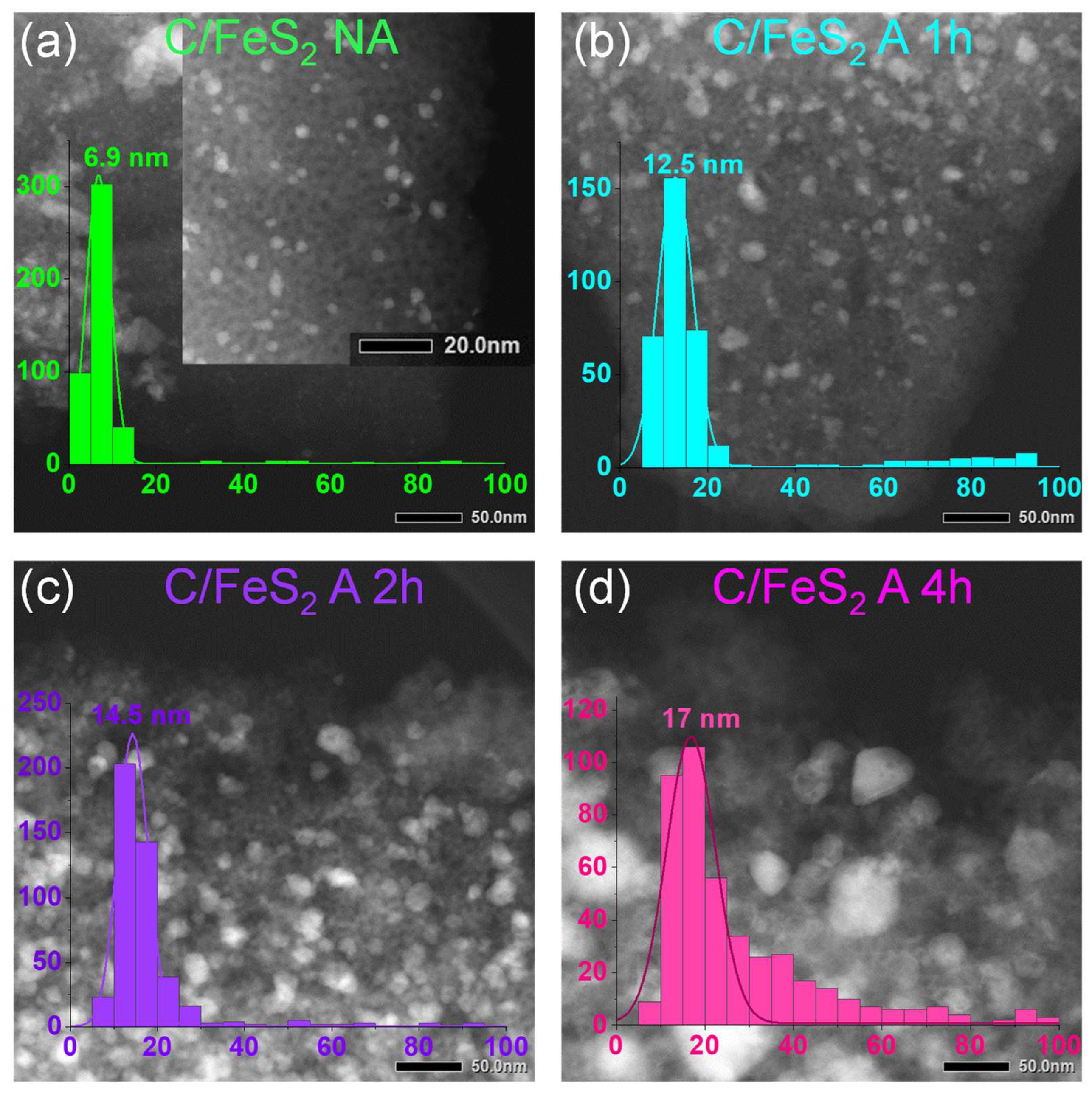
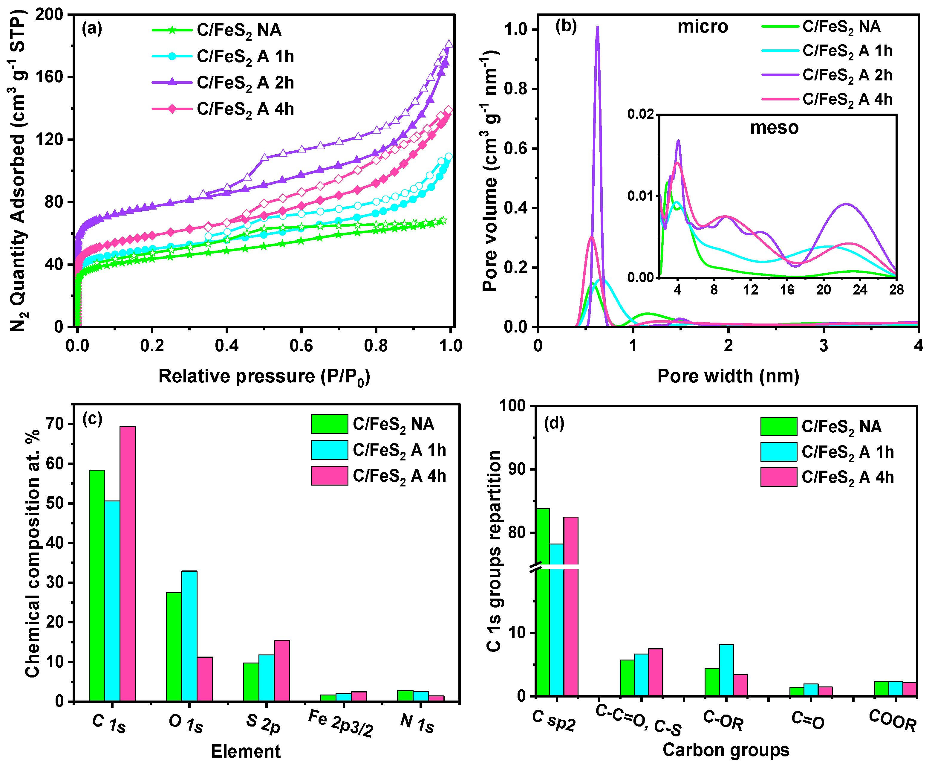
Figure 1. Synthesis scheme for the C/FeS2 composites; (1) nonactivated carbon/iron disulfide composites (C/FeS2 NA) and (2) activated carbon/iron disulfide composites (C/FeS2 A t, where A t means activation time). The scheme was created by the authors using BioRender software.
Carbon 09 00112 g001
Figure 2. (a) XRD diffractograms for the C/FeS composites obtained via sulfidation at different temperatures (250–600 °C) and (b) XRD data obtained after activation and sulfidation.
Carbon 09 00112 g002
Figure 3. STEM images and (inset) particle size distributions of the C/FeS2 composites; (a) nonactivated, (b) activated for 1 h, (c) activated for 2 h, and (d) activated for 4 h, then sulfidized at 400 °C.
Carbon 09 00112 g003
Figure 4. (a) Nitrogen adsorption/desorption isotherms, (b) pore size distributions determined with the 2D–NLDFT model for the C/FeS2 composites (nonactivated and activated for different times), main graph (0–4 nm), and inset mesopore region (2–28 nm), (c) chemical compositions determined from XPS survey spectra showing the different elements, and (d) partitioning of the C 1s groups obtained through deconvolution of the C 1s peaks for the synthesized C/FeS2 composites.
Carbon 09 00112 g004
Figure 5. (a) CVs from cycle 1 to cycle 49 for C/FeS2 A 4 h in a 3-electrode cell using 2 M KOH. (b) XRD data for the pristine electrode and for the same electrode after 50 cycles in a 3-electrode cell. STEM images of the (c) pristine electrode and (d) the same electrode after 50 cycles in a 3-electrode system.
Carbon 09 00112 g005
Figure 6. Electrochemical data obtained for the C/FeS2 composites in symmetric 2–electrode cells with 2 M KOH used as the electrolyte; (a) CV at 5 mV s−1 (b) charge–discharge cycles at 1 A g−1 (c) capacitance from 0.1 A g−1 to 10 A g−1 and (d) EIS at 0.0 V (inset: equivalent circuit diagram). The percentage values represent the rate capabilities.
Carbon 09 00112 g006
Figure 7. (a) Ragone plots for all C/FeS2 materials and (b) long–term cycling of C/FeS2 NA and C/FeS2 A 4 h at 1 A g−1 with voltages of 0.8 V; STEM images of C/FeS2 A 4 h; (c) the pristine electrode and (d) the same electrode after 10,000 cycles.
Carbon 09 00112 g007
Figure 8. (a) XRD ageing study of C/FeS2 NA at different time scales, (b) percentages of the crystalline phases present in C/FeS2 NA materials after different time periods, (c) initial and (d) final proportions of the crystalline phases in the C/FeS2 NA composite, (e) CVs run at 5 mV s−1 and (f) charge discharge curves at 1 A g−1.
Carbon 09 00112 g008
Table 1. Textural properties of the synthesized C/FeS2 materials determined through nitrogen adsorption, percentage of iron disulfide determined through TGA under air, and particle sizes (d) obtained using STEM.
MaterialSBET
(m² g−1)
VT (cm3 g−1)Vmicro (cm3 g−1)Vmeso (cm3 g−1)d STEM (nm)% FeS2 TGA (wt%)
C/FeS2 NA1610.100.060.0547.0015
C/FeS2 A 1 h1850.170.070.1012.5018
C/FeS2 A 2 h2960.280.110.1714.5022
C/FeS2 A 4 h2140.200.080.1317.0023
Disclaimer/Publisher’s Note: The statements, opinions and data contained in all publications are solely those of the individual author(s) and contributor(s) and not of MDPI and/or the editor(s). MDPI and/or the editor(s) disclaim responsibility for any injury to people or property resulting from any ideas, methods, instructions or products referred to in the content.

